1
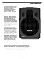
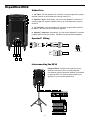
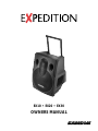
EX10 • EX20 • EX30
OWNERS MANUAL
®
Table of Contents
Introduction 3
System Features 4
EX10 6
EX20 8
EX30 10
Positioning and Mounting Instructions 14
Expedition Accessories 16
Specifications 17
Produced by On The Right Wavelength for Samson Technologies Corp.
Copyright 2000, Samson Technologies Corp.
Printed March 2000
Samson Technologies Corp.
575 Underhill Blvd.
P.O. Box 9031
Syosset, NY 11791-9031
Phone: 1-800-3-SAMSON (1-800-372-6766)
Fax: 516-364-3888
Introduction
Welcome to Samson Expedition—the portable audio system for the new millenium! This
exceptionally versatile system offers the perfect solution wherever you need portable,
high-quality audio: as a main PA system or as onstage monitors in clubs and
performance halls; in houses of worship; as a sound system for business presentations,
mobile DJs at parties, or aerobics instruction; and for use in outdoor environments such
as parks, beaches and flea markets. What’s more, every Expedition system comes with
a built-in telescoping handle and locking wheels, making it easy to take professional
audio with you wherever you go!
There are three different Samson Expedition systems detailed in this manual. All utilize
the same lightweight yet rugged two-way speaker enclosure that pairs a custom
designed 12" woofer with a matched 1" compression driver. The Expedition EX10 is a
passive 8-ohm enclosure that can be used with any external power amplifier rated at up
to 250 watts. The Expedition EX20 is a powered version that includes a bi-amped power
cell along with an active crossover, speaker protection circuitry and built-in limiting. And
the Expedition EX30 is designed as a total all-in-one portable PA system, adding a fourchannel stereo mixer—complete with digital effects—to the equation. In addition, a
number of expansion options are available, including a 500-watt active subwoofer (our
EX500); a rechargable Lead-Acid GelCel battery pack; and a rear-panel mountable
cassette recorder with pitch control. There's even a prewired custom compartment that
accommodates any of three different Samson wireless receivers!
In this manual, you’ll find a more detailed description of the features of all three
Expedition systems, as well as a guided tour through all components, step-by-step
instructions for setting up your system and full specifications. If your Expedition was
purchased in the United States, you’ll also find a warranty card enclosed—don’t forget
to fill it out and mail it! This will enable you to receive online technical support and will
allow us to send you updated information about this and other Samson products in the
future. If your Expedition system was purchased outside of the U. S., contact your
local distributor for warranty details. Also, be sure to check out our website
(http://www.samsontech.com) for complete information about our full product line.
SPECIAL NOTE for U.S. purchasers: Should your Expedition system ever require
servicing, a Return Authorization number (RA) is necessary. Without this number, the
unit will not be accepted. If your Expedition system was purchased in the United States,
please call Samson at 1-800-372-6766 for a Return Authorization number prior to
shipping your system. If possible, return the unit in its original carton and packing
materials. If your Expedition system was purchased outside of the U. S., contact your
local distributor for information.
3
System Features
The Samson Expedition system uses state-of-the art
technology to bring a revolutionary new degree of
flexibility and portability to professional audio. Its
main features include:
• A built-in telescoping handle and locking wheels
that make it easier than ever before to transport
your audio system.
S
S
M
A
N
O
• All Expedition enclosures are lightweight and
compact yet exceptionally durable and
roadworthy. Injection-molded with Polypropylene,
they feature substantial internal bracing to support
a nearly 1/2" thick side wall construction, making
them strong and rigid enough to allow maximum
energy to be delivered to the sound output.
In addition, a steel grill and scuff-resistant
textured finish makes for a rugged speaker
enclosure that will deliver dependable
performance in even the most demanding
environments.
• The low frequency section includes a custom
designed Kevlar-impregnated 12" low frequency
driver with a 2.5" Kapton Former voice coil and
50 ounce barium ferrite magnet for accurate and
super-tight bass response.
• A high frequency section that delivers clear,
sweet top end thanks to its 1" compression driver
with a specially designed phenolic diaphragm,
along with a phasing plug for linear response and
an elliptical wave guide horn design that reduces
nearly all sonic diffraction.
• A tilt position that allows the Expedition to be used
as an onstage wedge monitor.
• Integral 1 3/8" pole-mount receptacle and convenient fly points allow the
Expedition to be pole-mounted or “flown” using standard PA hardware.
• The EX10 is a passive cabinet that can be used with any power amplifier
rated at up to 250 watts into 8 ohms. It requires no power and provides
dual Speakon™ and 1/4" connectors that allow multiple EX10s to be
daisy-chained where extended coverage is required.
• The EX20 contains dual power amplifiers and an active crossover.
Operating in a biamped configuration, one power amp drives the low
frequency section with 150 watts of power and the other drives the high
frequency section with 50 watts of power. The active crossover uses an
advanced Linkwist-Riley constant phase filter that provides a steep rolloff of
24 dB per octave to reduce sonic distortion at the crossover frequencies.
Dual balanced XLR connectors allow daisy-chaining of multiple Expedition
enclosures, and a switchable limiter circuit assures a clean output even
when you’re pushing the EX20 to maximum levels. In addition, there are
three stages of speaker protection, including relay switching for power on
and off.
4
System Features
• The EX30 includes all the features of the
EX20, and adds a flexible four-channel
stereo mixer that provides two
monophonic and one stereo mic/line
channels with dual XLR and 1/4"
connectors. In addition, separate dual
phono connectors allow you to hook up
an external cassette or CD player.
Each mixer channel includes two-band
equalization and independent volume
control, and there’s even built-in digital
effects for the addition of six different
reverb presets. Balanced left and right
XLR outputs allow daisy-chaining of
multiple Expedition speakers (with a
mono/stereo switch that allows operation
in either mode), and a VU meter enables
you to continuously monitor output levels.
The EX20 and EX30 also include a meter
that shows battery level when used with
the optional RB 2030 rechargable battery
cartridge (see below).
• The top panel of both the EX20 and
EX30 provides a prewired compartment
that accommodates a variety of Samson
wireless systems that offer superior RF
and audio performance already proven
on stages around the world. Receivers
supported include the UM1 or M32 UHF
models or the VM1 VHF model.
• A wide range of optional accessories,
including: the MP 1030 mounting bracket,
which allows any Expedition enclosure to
be “flown” from the ceiling; the RB 2030
rechargable battery cartridge, which
provides up to two hours of power to
either the EX20 or EX30 from its dual
Lead-Acid GelCel batteries; and the TD30 cassette recorder, which fits neatly into a
special compartment above the EX30’s mixer to provide background music and/or
to record meetings or performances. The TD30 even includes a pitch control so you
can alter the tempo of the music for applications like aerobic instruction.
• The EX500 is an active subwoofer that pairs a massive 500-watt amplifier with a
heavy-duty 15" low frequency driver. It is an ideal complement to any Expedition
enclosure or any loudspeaker system, when the application requires deep, powerful
low end response. Its built-in stereo electronic crossover allows the EX500 to
operate either in mono or as a common subwoofer in a stereo system. It features
an all-steel grill and rigid corners, as well as an integral pole mount.
5
Expedition EX10
Guided Tour
1: 1/4" input - Use this standard 1/4" connector to connect signal from a power
amplifier (rated at up to 250 watts into 8 ohms) to the EX10.
2: Speakon™ input - Alternatively, you can use this Speakon™ connector to
connect signal from a power amplifier (rated at up to 250 watts into 8 ohms) to
the EX10.
3: 1/4" extension - Use this standard 1/4" connector to daisy-chain one EX10
to another. See below for interconnection diagrams.
4: Speakon™ extension - Alternatively, you can use this Speakon™ connector
to daisy-chain one EX10 to another. See below for interconnection diagrams.
Speakon™ Wiring
SPEAKON™
+
1-
1+
2+
2-
SPEAKON™
NOT CONNECTED
Interconnecting the EX10
Using one EX10: A single mono signal (bus or aux
send) is routed from a mixer to a power amplifier.
One speaker output of the power amplifier is connected
to either the EX10 1/4" input connector (solid line) or
Speakon™ input connector (dotted line).
SAMSON
SAMSON
SERVO - 240
MMPL2242
MPL2242
MPL2242
6
Expedition EX10
Using two EX10s in mono: A single mono signal (bus or aux send) is routed from a mixer to a power amplifier. One
speaker output of the power amplifier is connected to either the EX10 1/4" input (solid line) or Speakon™ input (dotted
line), and a connection is made between either the 1/4" extension to a second EX10’s input (solid line) or between the
Speakon™ extension to a second EX10’s Speakon™ input (dotted line).
SAMSON
SERVO - 240
SAMSON
MMPL2242
MPL2242
MPL2242
Using two EX10s in stereo: A stereo signal (bus or aux send) is routed from a mixer to a power amplifier. The left
speaker output of the power amplifier is connected to one EX10 (using either the 1/4" input [solid line] or Speakon™ input
[dotted line]), and the right speaker output of the power amplifier is connected to the other EX10 (again using either the
1/4" input [solid line] or Speakon™ input [dotted line]).
SAMSON
SERVO - 240
SAMSON
MMPL2242
MPL2242
MPL2242
7
Expedition EX20
Guided Tour
1: Input connector - Use this balanced female XLR connector to route
line-level signal into the EX20.
2: Output VU meter - This three-segment bar meter shows the EX20
output level. For optimum signal-to-noise ratio, set the Volume control
(see #6 below) so that program material is usually at or around 0 VU, with
occasional but not steady excursions to the red “+3 dB” segment.
3: Power switch - Use this to turn power to the EX20 on or off.
4: Voltage selector - Make sure this is set correctly for the country you are
in before turning on the power to the EX20.
5: Battery VU meter - If an optional RB 2030 rechargable battery pack is
installed, this meter shows how much battery power remains as it is being
charged (Power switch off) or depleted (Power switch on).
5
0
10
6: Volume control - This knob sets the level of the EX20’s built-in power
amplifiers.
!
7: Output connector- This balanced male XLR connector carries line-level
output signal from the EX20. It is used to send signal to a second EX20
being daisy-chained (see interconnection diagram on the following page)
or to an optional EX500 subwoofer.
8: Limiter switch - Use this switch to turn the built-in limiter circuitry on or
off. In order to maximize speaker protection, we recommend that this
switch be left in the “on” position during normal operation.
9: AC output - A standard AC power outlet.
10: AC input - Connect the supplied heavy-gauge 3-pin “IEC” power cable
here.
Interconnecting the EX20
Using one EX20: A single mono signal (bus or aux send)
is routed from a mixer to the EX20 XLR input.
5
0
10
!
SAMSON
MMPL2242
MPL2242
MPL2242
8
Expedition EX20
Using two EX20s in mono: A single mono signal (bus or aux send) is routed from a mixer to one EX20’s XLR input, and
a connection is made between that EX20’s XLR output to a second EX10’s XLR input.
5
5
0
0
10
10
!
!
SAMSON
MMPL2242
MPL2242
MPL2242
Using two EX20s in stereo: A stereo signal (bus or aux send) is routed from a mixer, with the left side connected to one
EX20’s XLR input, and the right side connected to the other EX20’s XLR input.
5
5
0
0
10
10
!
!
SAMSON
MMPL2242
MPL2242
MPL2242
9
Expedition EX30
Guided Tour
1: Equalizer - These controls allow you to shape your sound by boosting or
cutting the amount of bass (at 100 Hz) or treble (at 10 kHz) by up to 15 dB.
A center detent in each knob indicates no boost or cut (that is, flat response).
As each knob is turned clockwise from the 12 o’clock position, the bass or treble
is boosted; as it is turned counterclockwise from the 12 o’clock position, the bass
or treble is reduced.
2: Reverb send - These knobs determine how much signal is being sent from
the channel to the onboard DSP effects processor. As you move the knob clockwise from 0 to 10, more signal is sent. To hear the effect, one of the six presets
must be selected using the DSP Effects control (see #10 on the next page). Be
careful not to send too much signal to the DSP, or a distorted sound will result.
2
3: Pan/Balance control - In channels 1 and 2, this knob acts as a Pan control,
allowing you to place the signal anywhere in the left-right stereo spectrum, while
keeping the overall signal level constant. When the knob is placed at its center
(detented) position, the signal is sent equally to both the left and right outputs.
To route a signal hard left or right, place the pan knob either fully counterclockwise or fully clockwise.
In channel 3/4 (the stereo channel), this knob acts as a Balance control, allowing
you to alter the relative levels of the two input signals. When the knob is placed
at its center detented position, both signals are at equal strength. When moved
left of center, you’ll hear more of the left input signal; when moved right of center,
you’ll hear more right input signal.
4: Channel volume control - This knob determines the level of the channel
In stereo channel 3/4, this knob simultaneously controls the level of both inputs
(the relative levels of the two can be adjusted with the Balance knob, as
described in #3 above). In practice, you’ll use the channel volume controls to
continuously adjust the levels of the various signals being blended together by
the EX30 mixer.
5
0
5
0
5
5
10
REVERB
0
10
10
REVERB
0
10
REVERB
!
10
Expedition EX30
5: Insert (sub) connector - This 1/4" connector brings line-level signal in directly before the
EX30 power amplifiers. It is normally used to return signal from an optional EX500 subwoofer.
6: Line inputs - Use these 1/4" jacks to connect line-level sources to the EX30. Channels 1 and
2 are mono 1/4" connectors; channel 3/4 uses a stereo (TRS) 1/4" connector, with tip carrying left
signal and ring carrying right signal. Stereo devices should always be connected to the stereo
channel (channels 3/4). If a wireless receiver is connected to the EX30 via its internal
connectors (see page 14 in this manual), its output arrives at channel 2, which can also carry
another line-level source connected to its line input, as well as signal from a microphone
connected to its mic input. If an optional TD30 cassette player is installed, its output arrives at
channels 3/4, which can also carry another two line-level sources (one connected to its line input
and a second connected to the CD inputs [see #15 on the following page]), as well as signal from
a microphone connected to its mic input.
7: Mic inputs - Use these XLR jacks to connect microphones to the EX30’s built-in mic
preamps. Each channel can carry both one or more line level sources (see #6 above) as well
as a mic source.
8: DSP Effects control - Use this to select one of six reverb presets (Small Hall, Medium Hall,
Large Hall, Church, Stadium, or Plate). If you don’t want to hear any reverb, set this switch to the
“Off” position.
9: Mono/Stereo switch - When using one EX30, set this switch to “Mono” so that the EX30
power amp receives signal from both the left and right output sections. When using multiple
Expedition speaker enclosures, set this switch to “Stereo”; the EX30 will then reproduce only
signal from the left output section only (that is, signals panned left at the mixer); the Right output
can then be used to send signal from the right output section (that is, signal panned right at
the mixer) to a second enclosure. See the interconnection diagrams on pages 10 - 11 for more
information.
10: Outputs - The dual XLR connectors carry line-level output signal from the EX30. They are
used to send signal to a second EX30 (or EX20) being daisy-chained (see the interconnection
diagram on the following page) or to an optional EX500 subwoofer. Note that the signal being
output from these connectors is dependent upon the setting of the Mono/Stereo switch (see #9
above). When set to “Stereo,” the Left XLR connector carries left signal only and the Right XLR
connector carries right signal only; when set to “Mono,” both the Left and Right connectors carry
the same monophonic signal, summed from both the left and right output sections. See the
interconnection diagrams on pages 10 - 11 for more information.
11: Main Volume control - This knob determines the final output signal level—you can think of
this as being the “master fader.” Signals from all four channels are routed here just before being
routed to the EX30’s built-in power amplifiers and Left and Right output jacks (see #10 above).
12: Battery VU meter - If an optional RB 2030 rechargable battery pack is installed, this meter
shows how much battery power remains as it is being charged (Power switch off) or depleted
(Power switch on). See #20 on the following page.
13: Output VU meter - This three-segment bar meter shows the continuous output level of the
EX30. For optimum signal-to-noise ratio, try to adjust all channel and main Volume controls so
that program material is usually at or around 0 VU, with occasional but not steady excursions to
the red “+3 dB” segment.
14: Limiter LED - Lights whenever the built-in limiter is active. If you see this lighting frequently,
it means you’re overloading the EX30, so turn down one or more of the Channel volume controls
(see #4 on the preceding page) or the main Volume control (see #11 above).
11
Expedition EX30
15: CD inputs - Connect the outputs of a CD or tape player to this set of dual phono
jacks. Signal arriving here returns to stereo channel 3/4. If an optional TD30 cassette
player is installed, note that its output also arrives at channels 3/4, in addition to line-level
signal arriving at its 1/4" TRS line input (see #6 on the preceding page) and signal from a
microphone connected to its mic input (see #7 on the preceding page).
16: AC input - Connect the supplied heavy-gauge 3-pin “IEC” power cable here.
17: Limiter switch - Use this switch to turn the built-in limiter circuitry on or off.
In order to maximize speaker protection, we recommend that this switch be left in the
“on” position during normal operation.
18: Voltage selector - Make sure this is set correctly for the country you are in before
turning on the power to the EX30.
19: Gain switch - Sets the line-level TRS input of channel 3/4 (see #6 on the preceding
page) to either +4 (professional) or -10 (consumer) level.
20: Power switch - Use this to turn power to the EX30 on or off. If an optional
RB 2030 rechargable battery pack is installed, it will charge when this switch is in the
“Off” position.
Interconnecting the EX30
Using one EX30: In this example, microphones are connected to the XLR mic inputs of
channels 1 and 2, and a stereo keyboard is connected to the stereo 1/4" TRS connector
of channel 3/4 (using a Y-cord, with the tip carrying the left signal and the ring carrying
the right signal). IMPORTANT NOTE: When using just one EX30, always be sure to
set its Mono/Stereo switch to “Mono.”
2
12
Expedition EX30
Using one EX30 and an EX20 (stereo operation): In this example, microphones are connected to the XLR mic inputs of
channels 1 and 2 of an EX30, and a stereo keyboard is connected to the stereo 1/4" TRS connector of channel 3/4 of the
EX30 (using a Y-cord, with the tip carrying the left signal and the ring carrying the right signal). A connection is then
made between the Right output of the EX30 to the XLR input of an EX20. IMPORTANT NOTE: When using the EX30
with additional Expedition enclosures, always be sure to set the EX30 Mono/Stereo switch to “Stereo.”
2
5
0
10
!
Using one EX30 and three EX20s (extended range stereo operation): In this example, microphones are connected to
the XLR mic inputs of channels 1 and 2 of an EX30, and a stereo keyboard is connected to the stereo 1/4" TRS
connector of channel 3/4 of the EX30 (using a Y-cord, with the tip carrying the left signal and the ring carrying the right
signal). A connection is then made between the Left output of the EX30 to the XLR input of an EX20 (both will then carry
the same left channel signal). Finally, a connection is made between the Right output of the EX30 and an EX20, and
between that EX20’s XLR output and the XLR input of a third EX20 (both will then carry the same right channel signal).
IMPORTANT NOTE: When using the EX30 with additional Expedition enclosures, always be sure to set the EX30
Mono/Stereo switch to “Stereo.”
2
5
5
5
0
0
10
10
0
10
!
!
!
13
Positioning and Mounting Instructions
General Positioning Tips
• Operating a microphone or turntable in front of a speaker is a sure formula
for feedback and/or rumble problems, so always place the Expedition in
front of any mics or turntables that are being used.
• Use the Expedition upright for all “front-of-house” PA applications;
use it in its tilt-back position only for onstage monitoring.
• Always raise the speakers as high above the audience as is practicable
for maximum coverage.
• Use sufficient enclosures for the space you’re in. The larger the space,
the more speakers will be required.
Pole-Mounting
The underside of the Expedition contains a 1-3/8" stand mount socket that
allows it to be raised up on any standard speaker pole mounting (such as the
Ultimate Support Systems TS-30 or TS-33 speaker stands). Pole-mounting is
generally advisable when you want to maximize the distance that the
Expedition covers (sometimes called speaker “throw”).
If you are using an EX500 subwoofer, you can use its integral pole mount to
place an EX10, EX20 or EX30 immediately above it, creating a complete
column of sound.
Fly Mounting, Wall Mounting, and Ceiling Mounting
As shown in the illustration below, the top panel of the Expedition contains a
number of fly points, located in compartments to the left and right of the
wireless receiver compartment. The covers placed over these compartments
are simply attached with double-sided sticky tape, so just pull up to remove.
Expedition fly-mount points
14
Positioning and Mounting Instructions
Before fly-mounting, wall-mounting or ceiling-mounting the Expedition, you must
first install a Samson MP 1030 mounting bracket to the fly points, as shown in the
illustrations on the right
Standard cabling and hardware can then be attached to the MP 1030 mounting
bracket in environments where the Expedition needs to be “flown.”
In fixed installations where you wish to mount the Expedition to a ceiling, use the
OmniMount model 100-STMP mount, as shown in the illustration below:
Installing the MP 1030 mounting
bracket (top view)
In fixed installations where you wish to mount the Expedition from a wall, use the
OmniMount model 100-WB mount, as shown in the illustration below:
Top of Expedition with MP 1030
mounting bracket installed.
15
Expedition Accessories
As shown in the illustration on the left, the top panel of the Expedition EX20 and
EX30 provides a prewired compartment that accommodates any of three
different Samson wireless receivers: the UM1 or M32 UHF models or the VM1
VHF model. Output signal from a wireless receiver mounted in an EX30 arrives
at channel 2 of the onboard mixer.
In addition, a number of accessories are available from your local Samson
dealer that allow you to expand the capabilities of your Expedition system.
These include:
• The EX500 active subwoofer—the ideal complement to any Expedition
enclosure (or to any loudspeaker system, for that matter)—pairs a powerful
500-watt amplifier with a heavy-duty 15" low frequency driver in order to
provide deep low end response. A built-in stereo electronic crossover allows
the EX500 to operate either in mono or as a common subwoofer in a stereo
system. It features an all-steel grill and rigid corners, as well as an integral
1 3/8" pole-mount receptacle
EX20/EX30 wireless compartment
(top view)
• The RB 2030 rechargable battery cartridge, which provides up to two hours
of power to either the EX20 or EX30 from its dual Lead-Acid GelCel batteries.
-10
-3
• The MP 1030 mounting bracket, which allows any Expedition enclosure to
be “flown” or mounted on the wall or ceiling using standard OmniMount
hardware. For more information, see the “Positioning and Mounting the
Expedition” section on page 12.
0dB +4 +10
5
0
P L AY E R /
RECORDER
REW
F.FWD
REC/PLAY DECK
10
RECORD
LEVEL
AUTO LEVEL CONTROL
5
AUTO STOP
ONE TOUCH
100
50
0
0
SOFT
EJECT
10
PLAY
LEVEL
PITCH
CONTROL
REC
PLAY
REW
F.FWD
ST/EJ
PAUSE
STEREO PITCH CONTROLLED CASSETTE RECORDER/PLAYER
• The TD30 cassette recorder, which fits directly above the EX30’s mixer to
provide background music and/or to record meetings or performances.
2
Guided Tour: TD30
1: Transport controls - A set of standard transport controls, from left to right:
Record, Play, Rewind, Fast Forward, Stop/Eject, Pause. Both the Record and
Play buttons must be pressed in simultaneously to record signal.
2: Level meter - This five-segment bar meter shows the TD30 input level.
Excursions into the red “+10 dB” segment may indicate tape overloading and
distortion.
3: Record level control - Active only when recording. For optimum signal-to-noise ratio, set this control so that program material is usually at or around
0 VU on the Level meter (see #2 above), with occasional but not steady excursions to the red “+4 dB”
segment.
-10
-3
0dB +4 +10
5
0
PLAYER/
RECORDER
REW
F.FWD
REC/PLAY DECK
10
RECORD
LEVEL
4: Play level control - Sets the playback level.
When installed in an EX30, the TD30 output signal
arrives at mixer channels 3/4. See #6 on page 9 in
this manual for more information.
AUTO LEVEL CONTROL
5
AUTO STOP
ONE TOUCH
100
50
0
0
SOFT
EJECT
10
PLAY
LEVEL
5: Pitch control - In normal operation, leave this at
the 12 o’clock position. When at the 12 o’clock
position, the tape is played back at standard speed
and pitch. When moved clockwise from the 12
o’clock position, the tape is played back at a faster
speed (and higher pitch); when moved counterclockwise from the 12 o’clock position, the tape is
played back at a slower speed (and lower pitch).
PITCH
CONTROL
REC
PLAY
REW
F.FWD
ST/EJ
PAUSE
STEREO PITCH CONTROLLED CASSETTE RECORDER/PLAYER
16
Specifications
Power Rating: (@ 8Ω):
EX10
EX20, EX30
250 Watts Program; 400 Watts Max. Peak
160 Watts LF; 40 Watts HF
Frequency Response: (all models)
60 Hz – 15 kHz ± 3 dB
Sensitivity:
EX10
Crossover Frequency:
EX10
EX20, EX30
97 dB SPL @ 1W/1m
2.3 kHz (12 dB Per Octave)
2.3 kHz (24 dB Per Octave Linkwitz-Riley Constant Phase)
LF Driver: (all models)
12" heavy-duty driver ,
2.5" voice coil (Kapton Former),
50 oz. barium ferrite magnet
HF Driver: (all models)
1" compression driver
Stereo Mixer Section: (EX30 only)
Inputs
Outputs
Frequency Response
Crosstalk
Equalization Frequencies
Effects
Mounting: (all models)
Dimensions: (all models)
2 Mic/Line XLR/TRS,
1 Stereo Line w/Mic TRS/RCA/XLR
+4 Balanced XLR
10 Hz - 50 kHz
70 dB @ 1 kHz
100 Hz (Low), 10 kHz (High)
DSP Reverb with 6 Presets
Integral 1 3/8" Pole Mount Receptacle,
Fly Points
14 5/8 in. (w) x 17 3/8 (d) x 21 1/4 (h)
371 mm (w) x 441 (d) x 539 (h)
Weight:
EX10
EX20
EX30
28.5 lbs • 12.9 kg
42.0 lbs • 19.0 kg
45.0 lbs • 20.4 kg
17