1
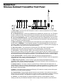
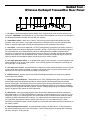
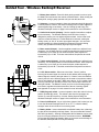
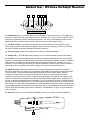
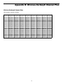
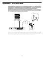
EarAmp
UHF WIRELESS IN EAR MONITOR
OWNERS MANUAL
U.S. Version
®
Table of Contents
Introduction 1
System Features 2
QuickStart 3
Guided Tour - Wireless EarAmp® Transmitter Front Panel 4
Guided Tour - Wireless EarAmp® Transmitter Rear Panel 5
Guided Tour - Wireless EarAmp® Receiver 6
Setting Up and Using the Wireless EarAmp® 8
Appendix A: Setting the Wireless EarAmp® Radio Frequency 10
Appendix B: Wireless EarAmp® Channel Plan 11
Appendix C: Using 2 CH Mode 12
Appendix D: Using Third-Party Earpieces 13
Specifications 14
Produced by On The Right Wavelength for Samson Technologies Corp.
Copyright 1999, Samson Technologies Corp.
Printed October 1999
Samson Technologies Corp.
575 Underhill Blvd.
P.O. Box 9031
Syosset, NY 11791-9031
Phone: 1-800-3-SAMSON (1-800-372-6766)
Fax: 516-364-3888
Introduction
We know you don’t like reading owners manuals, but you’ve just purchased one of the most unique
wireless audio products around, and we want to tell you about it! So, before you plug in and start making
music, we’d like to suggest you take just a few moments out to scan these pages. We’ll make it as
painless as possible, we promise—and, who knows, you might just pick up a tip or two.
The Samson Wireless EarAmp® is designed to bring professional in-ear monitoring to a wide range of
users. By eliminating the need for loud onstage “wedge” monitors, it allows you to hear yourself better,
greatly reduces feedback problems, and makes the overall sound coming from the stage significantly
cleaner. You’ll find that this portable, lightweight system provides superlative audio quality and extensive
control at an extremely affordable price. Capable of operating in both stereo and dual mono “2-channel”
mode, the Wireless EarAmp® receiver provides individual volume and balance controls for the best
possible mix, separate bass and treble controls to fine-tune the signal, and a built-in adjustable limiter to
protect your ears. The Wireless EarAmp® transmitter also offers a host of advanced features, including
stereo/mono operation, dual stereo inputs with independent level controls and 15 dB attenuation pads,
dual headphone outputs with dedicated level control, “daisy-chain” input/outputs for routing signal to or
from external devices, a large backlit LCD display and a 5-segment audio VU meter—there’s even
provision for optional computer remote control! Operating in the 614 - 662 MHz range, the Wireless
EarAmp® system is extraordinarily frequency-agile, meaning that it can be used almost anywhere in the
United States, and a unique automatic programming feature allows the receiver to instantly be set to the
same radio frequency as the transmitter, with just the push of a single button.
In these pages, you’ll find an overview of Wireless EarAmp® features, a “Quickstart” (for those of you
with wireless experience), and a guided tour of its various controls. Then we’ll detail how to set up the
Wireless EarAmp® as well as how to adjust it for the best sound quality. Finally, we’ll wrap things up with
reference appendices and full specifications. You’ll also find a warranty card enclosed—please don’t forget to fill it out and mail it so that you can receive online technical support and so we can send you updated information about other Samson products in the future. Also, be sure to check out our website
(http://www.samsontech.com) for complete information about our full product line.
SPECIAL NOTE: Should your Wireless EarAmp® system ever require servicing, a Return Authorization
number (RA) is necessary. Without this number, the unit will not be accepted. Please call Samson at
1-800-372-6766 for a Return Authorization number prior to shipping your unit. Please retain the original
packing materials and, if possible, return the Wireless EarAmp® in its original packing materials.
WARNING!
This product is capable of causing permanent damage
to your hearing if used at excessive volumes!
To protect your hearing, the Samson Wireless EarAmp® should always be used at as
low a volume as possible. We recommend that you stringently follow the guidelines
established by the U.S. Occupational Safety Health Administration (OSHA) regarding
maximum time exposure at various sound pressure levels:
•
•
•
•
•
•
•
Don’t use this product for more than 8 hours at 90 dB SPL
Don’t use this product for more than 4 hours at 95 dB SPL
Don’t use this product for more than 2 hours at 100 dB SPL
Don’t use this product for more than 1 hour at 105 dB SPL
Don’t use this product for more than 1/2 hour at 110 dB SPL
Don’t use this product for more than 15 minutes at 115 dB SPL
Don’t operate at listening levels of greater than 120 dB SPL!
Pay attention to what your ears are telling you! Ringing is a sign that you have set the
gain levels too high and that damage may result. We recommend that you consult with a
qualified audiologist if you exhibit ringing or any other symptoms.
1
Wireless EarAmp® System Features
The Samson Wireless EarAmp® system utilizes state-of-the-art technology in personal monitoring.
Its main features include:
• Excellent audio quality, with superior frequency response and low distortion.
• An extraordinary degree of frequency agility. The operating frequency can be selected either by
Group and Channel (there are 8 Groups of 16 Channels each) or by direct frequency selection (in
25 kHz increments between 614.35 and 662.0 MHz). This makes the Wireless EarAmp® eminently
suitable for traveling performances and allows it to be used in even the most “RF-hostile” urban
environments.
• Group numbers correspond to U.S. TV channel numbers so it is easy to select a known vacant
channel.
• Any number of receivers can be used with a single transmitter.
• Unique automatic receiver program function allows RF resetting at the push of a single button.
• PLL synthesized technology minimizes spurious emissions and provides solid, stable performance.
• Convenient belt clip for and flesh-colored ear buds for unobtrusive, nearly “invisible” usage.
• Receiver offers dedicated volume and center detented balance controls, along with independent bass
and treble controls allow each user to set up the optimum in-ear mix. There’s even a Loudness
switch for improved legibility when operating at low signal levels.
• Receiver provides stereo and dual mono (“2 CH”) modes for maximum flexibility. In “2 CH” mode, the
balance control enables you to adjust the blend of the two incoming signals, which are mixed internally to mono and routed to both ear buds.
• Receiver has a high-powered 200 mW 1/8" (Walkman-type) headphone output, while the transmitter
offers dual 1/4" and 1/8" (Walkman-type) headphone jacks.
• Built-in adjustable limiter helps protect your ears from transients and signal overloads.
• Receiver utilizes microprocessor true diversity for maximum range, tone key squelch for rejection of
spurious signals, and noise reduction for crystal-clear sound.
• Receiver operates on a standard 9-volt battery, with battery life of four hours or more.*
• Battery LED indicator shows you when the receiver battery needs to be replaced.
• Unique “daisy-chain” parallel inputs/outputs allow a third signal source to be input or external
monitoring of incoming audio signal to the transmitter.
• Transmitter operates in stereo or mono mode, and provides dual inputs (Main and Aux), with
independently adjustable input level for each, as well as a five-segment input level VU meter to allow
optimum gain settings. In addition, a large back-lit LCD display also shows the currently selected
Group/Channel and radio frequency.
• Switchable 15 dB pad for main and auxiliary inputs allows the Wireless EarAmp® system to be used
with a wide variety of signal sources.
• Transmitter is rack-mountable in any standard 19" rack (taking only a single space) for portability and
easy integration into existing systems.
• Computer interface allows optional remote control of all transmitter functions via software.
• Rugged construction of all components makes the Wireless EarAmp® eminently roadworthy.
* Typical usage. Actual battery life may vary depending upon headphone output level.
2
QuickStart
If you’ve had some prior experience using wireless systems, these QuickStart instructions will get you up
and running with your Wireless EarAmp® system in a matter of minutes! Detailed instructions for setting
up and using your Wireless EarAmp® can be found on pages 8 -11 of this manual, and the “Guided Tour”
sections on pages 4 - 7 provide full descriptions of all transmitter and receiver controls and displays.
1. Physically place the transmitter where it will be used, install its antenna, and extend it vertically.
2. Place a fresh battery in the receiver and turn it on momentarily to check it; the receiver’s Battery LED
will light red if the battery is weak and needs to be replaced.
3. Turn off all audio equipment in your system and connect your mixer’s line, aux or cue outputs to the
transmitter’s Main inputs. If you want to transmit additional signal, use the Aux and/or Daisy Chain
inputs.
4. Connect the supplied AC adapter (don’t use substitutes!) to the DC Input on the rear panel of the
transmitter (first looping the cable around the strain relief), then plug it into a 3-pin grounded AC socket.
5. Set the Phones Level and Input Level controls on the transmitter to minimum (to the “-10” position)
and then turn the transmitter on by pressing its Power switch; the front-panel LCD will light up.
6. Turn on the power to the receiver, place both of its antennas in an upright position, and set the
Volume knob to minimum (fully counterclockwise). Do not place the earbuds in your ears yet.
7. Set the transmitter to either Group/Channel mode (by pressing the CH. button) or Frequency mode
(by pressing the FREQ button). Group/Channel mode must be used whenever there are two or more
transmitters being used in the same location.
7a. If in Group/Channel mode, use the Up/Down buttons to select a Channel. Press both the CH. and
FREQ buttons simultaneously to enable Group selection (again, using the Up/Down buttons).
7b. If in Frequency mode, use the Up/Down buttons to select a frequency between 614.35 and 662.0
MHz, in 25 kHz increments.
8. To set the receiver to the same radio frequency, turn its Program switch off, then on (towards the “up”
arrow) and then, within ten seconds, press and hold the transmitter’s Program button for at least three
seconds. When correctly programmed, the receiver’s TX LED will flash.
9. Do a walkaround through the intended area of coverage while observing the receiver’s TX LED as you
do so (it will light steadily green when receiving valid tone pilot signal). Reposition antennas or select a
different Group/Channel or frequency as necessary.
10. Turn on your mixer and set the level of the signal you’re sending to the transmitter to unity gain
(0 vu). Then slowly raise the transmitter’s Input Level control while observing the level meters; the “0”
segment should light frequently, the “+6” segment only infrequently. If you have signal connected to the
Aux inputs, use a screwdriver to adjust the rear-panel Aux Input control. If you are sending very hot
signal to the transmitter, you may need to set either the Main and/or Aux Attenuator switch to “-15 dB.”
The audio signal can be monitored by connecting a pair of headphones to the transmitter and slowly
raising the Headphone Level control or by connecting the Daisy-Chain outputs to an external monitoring
system.
11. Set the receiver’s 2 CH/Stereo mode switch as desired (see Appendix C for details). Connect the
supplied earbuds (or third-party earpiece) to the receiver’s headphone jack and place them in your ears.
Slowly turn up the receiver’s volume control until you achieve the desired level. The EarAmp® receiver
should always be used at as low a volume as possible. If you hear ringing in your ears, turn
down the volume control and operate it at a lower level!
12. Adjust the receiver’s Balance control and Limiter Level, Bass and Treble trimpots as desired. If
you’re operating at low signal levels, turning the loudness control on will help improve legibility. Close the
battery door and clip the receiver to your belt.
3
Guided Tour Wireless EarAmp® Transmitter Front Panel
1
SAMSON
2a 2b
3
4
5 6 7 8
10
11
ANTENNA
PHONES
PHONES LEVEL
EarAmp
®
INPUT LEVEL
LEFT
+6
STEREO TRANSMITTER
-2
0
2
-4
-2
4
-6
6
0
0
2
-4
-6
4
RT80 UHF SYNTHESIZED
8
-10
10
RIGHT
CH.
UP
PROGRAM
GROUP
-12
-6
DOWN
6
-18
-8
POWER
9
-8
FREQ
8
-10
10
1: Power switch - Use this to turn the main power on and off. When the transmitter is on, the display
section (see #9 below) is lit.
2a: 1/4" Headphone jack - Connect any standard stereo headphones to this jack (via a 1/4" TRS plug)
in order to monitor the audio signal connected to the transmitter’s rear panel input jack(s) (see #3, #7,
and #8 on the following page). The built-in headphone preamp delivers approximately 200 mw of power.
2b: 1/8" (35 mm) Headphone jack - Connect any Walkman-style stereo headphones to this jack (via a
1/4" TRS plug) in order to monitor the audio signal connected to the transmitter’s rear panel input jack(s)
(see #3, #7, and #8 on the following page).
3: Phone Level control - This knob sets the level of the signal sent to the headphone jacks (see #2a
and #2b above). WARNING: To avoid possible damage to connected headphones (or, worse yet, to
your ears!), always turn this all the way off (to the fully counterclockwise “0” position) before plugging in a
pair of headphones—then raise the level slowly while listening.
4: Input Level control - This knob sets the incoming level of the audio signal connected to the
transmitter’s Main rear panel input jack(s) (see #3 on the following page). See #5 below.
5: Level meters - These five-segment “ladder” meters (similar to the VU bar meters used on audio
devices) show the strength of incoming audio signal. For best signal-to-noise ratio, adjust the Input Level
control (see #4 above) so that the yellow “0” segment lights frequently, with the red “+6” segment lighting
only infrequently during the very highest signal peaks. If you hear distortion, back the control off slightly.
6: CH. (Channel) button - Press this button to place the Wireless EarAmp® transmitter in
“Group/Channel” mode. See the “Setting Up and Using The Wireless EarAmp®” section and Appendix A
on pages 8 and 10 of this manual for more information.
7: FREQ (Frequency) button - Press this button to place the Wireless EarAmp® transmitter in
“Frequency” mode. See the “Setting Up and Using The Wireless EarAmp®” section and Appendix A on
pages 8 and 10 of this manual for more information.
8: Up/Down buttons - Use these to select the desired Group or Channel (when the transmitter is in
“Group/Channel” mode) or to select the desired frequency (when the transmitter is in “Frequency” mode).
See the “Setting Up and Using The Wireless EarAmp®” section and Appendix A on pages 8 and 10 of
this manual for more information.
9: Display - This backlit two-line Liquid Crystal Display (LCD) shows the currently selected Group and
Channel or the currently selected frequency.
10: Program button - Press and hold down this button for two seconds or more within ten seconds of
turning on the receiver Program switch (see #7 on page 6) in order to reprogram the receiver to utilize the
currently selected frequency. See Appendix A on page 10 of this manual for more information.
11. Antenna - In normal operation, the antenna should be placed in a vertical position. See the
“Setting Up and Using The Wireless EarAmp®” section on page 8 of this manual for more information.
4
Guided Tour Wireless EarAmp® Transmitter Rear Panel
1
2
3
4
5
3
6
8
7
9
8
PUSH
PUSH
CAUTION
USE SAMSON
AC ADAPTOR
ONLY
RT80 UHF SYNTHESIZED STEREO MONITOR TRANSMITTER
-2
STEREO
0dB
MONO
-15dB
0
4
-10
MADE IN USA
-
LEFT AUX INPUT
(MONO)
AUX INPUT
ATTENUATOR
RIGHT AUX INPUT
2
1
3
0dB
-15dB
1
3
XLR
1 GND
2 HOT
3 COLD
A
6
8
-8
SERIAL NUMBER
2
2
-4
-6
LOOP THRU
+
DAISY CHAIN
AUXILIARY
CABLE LOCK:
AND TIE
MAIN INPUTS
INTERFACE
SAMSON
DC INPUT
10
AUX INPUT LEVEL
RJ45 SERIAL PORT
PARALLEL LEFT
IN/OUT
PARALLEL RIGHT
IN/OUT
INPUT LEFT (MONO)
ATTENUATOR
INPUT RIGHT
1: DC input - Connect the supplied power adapter here, using the strain relief as silkscreened on the
rear panel. WARNING: The substitution of any other kind of power adapter can cause severe damage to
the Wireless EarAmp® transmitter and will void your warranty.
2: Stereo/Mono switch - When set to “Stereo,” the incoming left and right audio signal(s) are kept
separate; when set to “Mono,” only signal connected to the left Main and.or Aux input (see #4 and #8
below) is used (the right signal is muted) and is transmitted to both channels of the receiver.
3: Aux Inputs - Use these two balanced 1/4" TRS (Tip/Ring/Sleeve) jacks when you wish to connect a
secondary signal to the Wireless EarAmp® transmitter. Wiring is Tip hot, Ring cold, and Sleeve ground.
We recommend the use of balanced three-conductor cabling wherever possible (unbalanced twoconductor 1/4" plugs can also be inserted into these inputs, but you’ll get better signal quality and less
outside noise and hum if you use balanced lines). When connecting a monophonic signal, use the left
jack only and set the Stereo/Mono switch (see #2 above) to the “Mono” position.
4: Aux Input Attenuator switch - A 15 dB attenuator (pad) for the Aux inputs. In normal operation, this
switch should be set to the left “0 dB” position. If the incoming signal is too strong and is distorting, set
this to the right “-15 dB” position.
5: Aux Input Level control - Use a screwdriver to adjust this control until the desired level of Aux signal
(relative to the Main signal) is reached. If nothing is connected to the Aux Inputs (see #3 above), this
should be left at its fully counterclockwise position (completely off).
6: RJ45 Serial Port - Used to connect the Wireless EarAmp® transmitter to a computer for optional
remote control via software.
7: Daisy Chain Inputs/Outputs - These balanced 1/4" TRS (Tip/Ring/Sleeve) jacks are wired in parallel
with the Main inputs (see #8 below) and can be used to route the incoming Main signal to external
devices at unity gain. Alternatively, they can be used as inputs, bringing a third stereo or mono signal
into the Wireless EarAmp® transmitter (albeit without an attenuator switch or level control) if necessary.
Wiring is Tip hot, Ring cold, and Sleeve ground. See the “Setting Up and Using The Wireless EarAmp®”
section on page 8 of this manual for more information.
8: Main Inputs - Connect incoming signal to these electronically balanced Combination connectors,
using either XLR or 1/4" TRS (Tip/Ring/Sleeve) connectors, wired as follows: Pin 2 (or Tip) hot, Pin 3 (or
Ring) cold, and Pin 1 (or Sleeve) ground. We recommend the use of balanced three-conductor cabling
wherever possible (unbalanced two-conductor 1/4" cables can also be inserted into these inputs, but
you’ll get better signal quality and less outside noise and hum if you use balanced lines). When
connecting a monophonic signal, use the left jack only and set the Stereo/Mono switch (see #2 above) to
the “Mono” position.
9: Main Input Attenuator switch - A 15 dB attenuator (pad) for the Main inputs. In normal operation,
this switch should be set to the left “0 dB” position. If the incoming signal is too strong and is distorting,
set this to the right “-15 dB” position.
5
Guided Tour - Wireless EarAmp® Receiver
1: Battery door release - Press this latch gently upwards in order to open
the battery door and access the controls contained within. When closing the
battery door, swing it gently upwards until you hear this latch click.
EarAmp®
1
2
2
SAMSON
UHF STEREO MONITOR AMP
2: Antennas - In normal operation, these two antennas should be placed in
a vertical position; however, the swivel mountings can be used to adjust the
antenna positioning as necessary. See the “Setting Up and Using The
Wireless EarAmp®” section on page 8 of this manual for more information.
3: Limiter level control (trimpot) - Use the supplied screwdriver to adjust
this as necessary. The Wireless EarAmp’s built-in limiter circuitry is
designed to protect your ears against signal overload. As the limiter level
control is turned clockwise, the limiter threshold is reduced, causing the
limiting circuitry to “kick in” at lower input signal strengths. As it is turned
counterclockwise, the limiter threshold is increased, so that the limiting
circuitry only operates at relatively high input signal strengths.
4. Bass control (trimpot) - Use the supplied screwdriver to adjust this as
necessary. As the bass control is turned counterclockwise, bass response
is reduced by up to 10 dB; as it is turned clockwise, bass response is
increased by up to 10 dB. The bass control affects frequencies at around
150 Hz.
6
7
5: Treble control (trimpot) - Use the supplied screwdriver to adjust this as
necessary. As the treble control is turned counterclockwise, treble response
is reduced by up to 10 dB; as it is turned clockwise, treble response is
increased by up to10 dB. The treble control affects frequencies at around
5 kHz.
8
EarAmp
®
1
ON
2 CH
A
2
3
4
STEREO
MODE
LIMITER LEVEL
BASS
-
OFF
PGM.
POWER
2
+
9
6. 2 CH / Stereo switch - When set to the down, “Stereo” position,
incoming left channel signal is routed to the left earbud and incoming right
channel signal is routed to the right earbud. In “Stereo” mode, the Balance
control (see #14 on the following page) can be used to increase the relative
level of one channel or the other. When set to the up, “2 CH” position, both
incoming channels are internally mixed to mono and routed to both the left
and right earbuds. The Balance control (see #14 on the following page) is
then used to regulate the relative amounts of the two incoming signals.
See Appendix C on page 12 in this manual for more information.
TREBLE
5
7. PGM (Program) switch - In normal operation, leave this switch in the up
position (towards the arrow). This switch is also used to reprogram the
receiver to a new RF frequency—see the “Setting Up and Using The
Wireless EarAmp®” section on page 8 of this manual for more information.
8. Power On/Off switch - As you might have guessed, this is what you use
to turn the Wireless EarAmp® receiver on or off. To conserve battery
strength, leave the unit off when it is not being used.
9. Battery holder - Insert a standard 9-volt alkaline battery here, observing
the plus and minus polarity markings shown. We recommend the Duracell
MN 1604 type battery. Although rechargeable Ni-Cad batteries can be used,
they do not supply adequate current for more than two hours. WARNING:
Do not insert the battery backwards; doing so can cause severe damage to
the Wireless EarAmp® and will void your warranty.
6
Guided Tour - Wireless EarAmp® Receiver
10
11
12 13 14 15
PHONES
R
L
LOUDNESS
VOLUME
TX
BALANCE
10: Headphone jack - Connect the supplied stereo earbuds (or third-party earpieces—see Appendix D
on page 13 in this manual for more information) to this standard 1/8" (3.5 mm) mini-phone jack in order to
monitor the signal being output by the Wireless EarAmp®. The level of the headphone signal is set by
adjusting the Volume control (see #12 below). Maximum output is 200 mW @ 32 ohms.
11: Loudness switch - At normal listening levels, this should be left off (with the switch to the left).
When using the Wireless EarAmp® at low signal levels, turning this on (placing the switch on the right)
will improve legibility by boosting both bass and treble frequencies.
12: Volume control - Use this to set the level of the signal in connected earbuds.
13: Battery LED - This LED lights red when battery level is low and the battery needs to be replaced.
14: TX LED - This LED lights steadily green whenever the Wireless EarAmp® receiver is receiving RF
signal from the transmitter and flashes when the receiver is being reprogrammed to operate at a different
radio frequency. Both the receiver and transmitter must be set to the same RF frequency for correct
operation. See the “Setting Up and Using The Wireless EarAmp®” section on page 8 of this manual for
information on how to program the receiver to operate at the selected transmitter frequency.
15: Balance control - Adjusts the relative levels of the two signals being received by the Wireless
EarAmp®. When set at the center 12 o’clock position, both signals are presented to connected earbuds
at equal strength. When the Wireless EarAmp® is operating in “Stereo” mode (that is, when the
2 CH/Stereo switch [see #6 on the previous page] is set to “Stereo,”) turning the balance control
clockwise increases the relative amount of right channel signal (that is, the signal in your right ear) and
turning it counterclockwise increases the relative amount of left channel signal (that is, the signal in your
left ear). When the Wireless EarAmp® is operating in “2 CH” mode (that is, when the 2 CH/Stereo switch
[see #6 on the previous page] is set to “2 CH,”) both channels are internally mixed to mono and routed to
both earbuds. In 2 CH mode, turning the balance control clockwise increases the relative amount of right
channel signal (though it will be heard in both ears) and turning it counterclockwise increases the relative
amount of left channel signal (again, heard in both ears). See Appendix C on page 12 in this manual for
more information
16: Belt clip - Use this to clip the Wireless EarAmp® receiver to your belt for convenient operation.
16
7
Setting Up and Using The Wireless EarAmp®
Setting up your Wireless EarAmp® is a simple procedure which takes only a few minutes:
1. Remove all packing materials (save them in case of need for future service) and locate the
Wireless EarAmp® transmitter so that there is an unobstructed line of sight between it and the receiver(s)
in your system (any number of receivers—all receiving the same signal—can be used with a single
transmitter. Be sure, however, that the receivers never come within 10 feet of the tranmitter antenna).
For convenience, the EarAmp® transmitter is rack-mountable, requiring just a single space. Mount the
supplied antenna to the transmitter by inserting the BNC connector and twisting clockwise until snug.
The antenna mounting is adjustable; however, it is best to begin with it in an upright position.
2. Press gently up on the EarAmp® receiver’s battery door release (see #1 on page 6) and swing the
door open in order to access the battery compartment. Note that the door is hinged and is not intended
to be removed from the case. Insert a 9-volt alkaline battery, being careful to observe the polarity
markings. Warning: Reversing the battery polarity may cause permanent damage to your
EarAmp® receiver.
3. Turn the receiver power switch “On” (see #8 on page 6). The Battery LED (see #13 on page 7) will
light red if the battery is weak and needs to be replaced. Once you’ve verified battery strength, turn the
power switch “Off” again.
4. Close the receiver battery door by swinging it gently upwards until you hear the door release click.
5. Turn off all audio equipment (mixers, amplifiers, etc.) in your system and make the physical cable
connections between your mixer (typically aux sends, cue sends or line outputs) and the Main inputs of
your Wireless EarAmp® transmitter. WARNING: Be sure to connect only line-level inputs to the
EarAmp® transmitter; connecting amplifier outputs or other powered (“speaker”) outputs can
cause severe damage and will void your warranty. If you want to transmit additional signal, use the
Aux inputs and/or the Daisy Chain inputs. Note that the Daisy Chain inputs can also serve as outputs,
routing the signal connected to the Main inputs at unity gain. We recommend the use of balanced threeconductor cabling wherever possible (unbalanced two-conductor 1/4" plugs can also be inserted into
these inputs, but you’ll get better signal quality and less outside noise and hum if you use balanced
lines). When connecting stereo signals, set the rear panel Stereo/Mono switch to the “Stereo” position.
When connecting monophonic signal(s), use the left jack(s) only and set the rear panel Stereo/Mono
switch to the “Mono” position.
6. Connect the supplied power adapter to the transmitter’s rear panel DC connector (first looping the
cable around the strain relief, as silk-screened on the rear panel) and plug the other end into any 3-pin
grounded AC socket. WARNING: The substitution of any other kind of power adapter can cause
severe damage to the Wireless EarAmp® transmitter and will void your warranty.
7. Turn the Phones Level and Input Level controls on the EarAmp® transmitter completely
counterclockwise (to the “-10” position) and depress the front panel power switch to turn the unit on.
The display section will light up.
8. Next, select the radio frequency you wish to use for your transmitter and receiver(s). Turn on the
power to your Wireless EarAmp® receiver, place both antennas in an upright position, and set the
Volume knob to minimum (fully counterclockwise). Do not place the earbuds in your ears yet.
8a. If only a single EarAmp® system is being used, the transmitter can be placed in “Frequency” mode
by pressing the front-panel Frequency button; the Up/Down buttons can then be used to directly enter the
desired radio frequency. However, if two or more transmitters and receivers are being used at the same
location, the Wireless EarAmp® transmitter must be set to Group/Channel mode, by pressing the frontpanel Channel button. In a multi-transmitter setup, all devices must be set to the same Group (though
each transmitter/receiver pair must use its own Channel) or intermodulation noise may occur. Press both
the Channel and Frequency buttons simultaneously; the word “Group” will begin flashing. The Up/Down
buttons can now be used to select the desired Group. Once you’ve selected the Group you want, press
the Channel button again and use the Up/Down buttons to select a Channel within that Group (see
Appendix B on page 11 in this manual for a complete channel plan).
8
Setting Up and Using The Wireless EarAmp®
8b. In the receiver, turn the Program switch off, then on (towards the “up” arrow) and then, within ten
seconds, press and hold the transmitter’s front-panel Program button for at least three seconds in order
to program the receiver; when correctly programmed, the TX LED on top of the receiver will flash (see
Appendix A on page 10 in this manual for more details). Note that the Program switch must always be
on (toward the “up” arrow) for correct operation of the receiver.
9. When first setting up the Wireless EarAmp® system in a new environment, it’s always a good idea to
do a walkaround while experimenting with different frequency settings, observing the receiver’s TX LED
as you do so. If the light fails to light steadily as you move through the area that needs to be covered ,
the receiver may be receiving interference and the selected frequency or Group/Channel is probably
unsuitable for use. Always pick the Group that has the greatest number of clear Channels and the
Channel providing the strongest signal. The basic rule of thumb for successful wireless installations is to
always try to minimize the distance between transmitter and receiver as much as possible (though not
less than 10 feet) and also to try to maintain “line of sight” between the two (so that the person using the
receiver can see the transmitter antenna). You may also be able to improve RF reception by relocating
the transmitter or repositioning antennas.
10. Once you’ve settled on the radio frequency you want to use, it’s time to set the audio levels. Turn on
your mixer and set the level of the signal you’re sending to the transmitter to unity gain (0 vu). Then
slowly raise the transmitter’s front-panel Input Level control while observing the level meters. For best
signal-to-noise ratio, adjust the Input Level control so that the yellow “0” segment lights frequently, with
the red “+6” segment lighting only infrequently during the very highest signal peaks. If you have signal
connected to the Aux inputs, use a screwdriver to adjust the rear-panel Aux Input control. If you are
sending very hot signal to the EarAmp® transmitter, you may need to set either the Main and/or Aux
Attenuator switch to “-15 dB.” To monitor the signal arriving at the transmitter, either connect a set of
headphones to either headphone jack and slowly raise the Headphone Level control or connect the
rear-panel Daisy-Chain outputs to an amp and speakers (or a pair of self-powered speakers). If you
hear distortion, back the Input Level control off slightly.
11. Set the receiver’s 2 CH/Stereo mode switch as desired. In Stereo mode, the two incoming signals
are routed to the left and right earbuds, respectively. In 2 CH mode, the two incoming signals are internally mixed to mono and both signals are routed to both earbuds. If the signal to be monitored is mono,
set the 2 CH / Stereo switch to the up, “2 CH” position. See Appendix C on page 12 in this manual for
more information about the use of 2 CH mode.
12. Start by setting the receiver’s Balance control (see #15 on page 7) to its center detented position.
and by turning the Loudness switch (see #11 on page 7) off.
13. Connect the supplied earbuds (or third-party earpiece—see Appendix D on page 13) to the
receiver’s headphone jack (see #10 on page 7) and place them in your ears.
14. Finally, while playing or singing at a normal performance level, slowly turn up the receiver’s volume
control until you achieve the desired level. The EarAmp® receiver should always be used at as low a
volume as possible. If you hear ringing in your ears, turn down the volume control and operate it
at a lower level!
15. Adjust the Balance control as needed in order to get the best blend of the incoming signals. If
necessary, use the supplied screwdriver to adjust the Limiter Level, Bass and Treble trimpots (see #3, 4
and 5 on page 6) in order to optimize the sound you’re hearing. If you’re operating at low signal levels,
turning the loudness control on will help improve legibility.
16. Close the battery door and clip the receiver to your belt.
If you encounter difficulty with any aspect of setting up or using your Wireless EarAmp®, you can call
Samson Technical Support (1-800-372-6766) between 9 AM and 5 PM EST.
9
Appendix A: Setting the Wireless EarAmp™
Radio Frequency
The Samson Wireless EarAmp® is extraordinarily frequency-agile, offering more than 128 different radio
frequencies and two different modes of operation. In Group/Channel mode, you can access a
factory-programmed channel plan (see Appendix B on the following page) that allows you to use up to
sixteen different systems together at the same location (assuming all frequencies are available).
Alternatively, Frequency mode allows you to directly “dial in” any radio frequency between 614.35 and
662.0 MHz, in 25 kHz increments. Either mode can be used when only one Transmitter (with any
number of receivers) is being utilized; however, in locations where more than one Transmitter is used,
we strongly advise the use of Group/Channel mode. Note that Group numbers correspond to U.S. TV
channel numbers, making it easy to select a known vacant channel.
To set the Wireless EarAmp® radio frequency in Group/Channel mode:
1.
2.
3.
4.
5.
6.
Press the transmitter’s front-panel CH. (Channel) button (this sets Group/Channel mode).
Press the front-panel CH. (Channel) and FREQ (Frequency) buttons simultaneously. The word
“Group” in the display will begin flashing.
Use the UP/DOWN buttons to select the desired Group, from 38 to 45 (these correspond to U.S.
TV channel numbers). Note that, if you make no selection within five seconds, the word “Group”
will stop flashing.
If the word “Group” is still flashing in the display, press the Channel button to stop it flashing.
Use the UP/DOWN buttons to select the desired Channel (from 1 to 16) within the selected
Group. The bottom line of the display shows the actual frequency of that Channel (see the
Channel Plan in Appendix B on the following page).
In the receiver, turn the Program switch off, then on (towards the “up” arrow) and then, within ten
seconds, press and hold the transmitter’s front-panel Program button for at least three seconds,
until the TX LED on the receiver flashes. This confirms that the receiver is set to the same
radio frequency as the transmitter.
The TX LED in the receiver will always light steadily green when it is correctly set to the same
frequency as the transmitter and is receiving pilot tone. If it does not do so, reprogram it
(following step 5 above) until you see the TX LED flash.
To set the Wireless EarAmp® radio frequency in Frequency mode:
1.
2.
3.
4.
Press the transmitter’s front-panel FREQ (Frequency) button (this sets Frequency mode).
Use the UP/DOWN buttons to select the desired Frequency, from 614.350 MHz to 662.000 MHz.
Each press of the UP/DOWN button increments or decrements the frequency by 25 kHz. Press
and hold down the UP or DOWN button to rapidly increase or decrease the frequency.
In the receiver, turn the Program switch off, then on (towards the “up” arrow) and then, within ten
seconds, press and hold the transmitter’s front-panel Program button for at least three seconds,
until the TX LED on the receiver flashes. This confirms that the receiver is set to the same
radio frequency as the transmitter.
The TX LED in the receiver will always light steadily green when it is correctly set to the same
frequency as the transmitter and is receiving pilot tone. If it does not do so, reprogram it
(following step 5 above) until you see the TX LED flash.
Note that both the transmitter and receiver in the Wireless EarAmp® system always retain their RF
settings even after being powered off—in the case of the receiver, even after the battery is removed.
10
Appendix B: Wireless EarAmp® Channel Plan
Wireless EarAmp® Channel Plan:
(All frequency values are in MHz)
Channel
Group
38
Group
39
Group
40
Group
41
Group
42
Group
43
Group
44
Group
45
1
2
3
4
5
6
7
8
9
10
11
12
13
14
15
16
614.35
616.10
616.50
617.40
619.30
620.00
614.70
615.05
615.40
615.75
617.00
617.80
618.15
618.50
618.85
619.65
620.35
622.10
622.50
623.40
625.30
626.00
620.70
621.05
621.40
621.75
623.00
623.80
624.15
624.50
624.85
625.65
626.35
628.10
628.50
629.40
631.30
632.00
626.70
627.05
627.40
627.75
629.00
629.80
630.15
630.50
630.85
631.65
632.35
634.10
634.50
635.40
637.30
638.00
632.70
633.05
633.40
633.75
635.00
635.80
636.15
636.50
636.85
637.65
638.35
640.10
640.50
641.40
643.30
644.00
638.70
639.05
639.40
639.75
641.00
641.80
642.15
642.50
642.85
643.65
644.35
646.10
646.50
647.40
649.30
650.00
644.70
645.05
645.40
645.75
647.00
647.80
648.15
648.50
648.85
649.65
650.35
652.10
652.50
653.40
655.30
656.00
650.70
651.05
651.40
651.75
653.00
653.80
654.15
654.50
654.85
655.65
656.35
658.10
658.50
659.40
661.30
662.00
656.70
657.05
657.40
657.75
659.00
659.80
660.15
660.50
660.85
661.65
11
Appendix C: Using 2 Ch Mode
The Wireless EarAmp®’s unique dual mono “2 CH” mode makes it possible for you to have direct control
over the blend of two separate signals, simply by turning the Balance knob. If you’re a vocalist, the most
typical application is to route the vocal signal only to one mixer aux send and the instrument
accompaniment signal to the other aux send, as shown in the illustration below. This way, by turning the
Balance knob one way, you’ll hear more of your vocal and less of the instruments; by turning it the other
way, you’ll hear less of your vocal and more of the instruments.
SAMSON
MMPL2242
MPL2242
MPL2242
Aux 1
out
(vocal)
Aux 2
out
(instruments)
EarAmp®
SAMSON
ANTENNA
PHONES
PHONES LEVEL
EarAmp
®
INPUT LEVEL
LEFT
+6
STEREO TRANSMITTER
-2
0
2
-4
-2
4
-6
6
0
0
2
-4
4
-6
POWER
RT80 UHF SYNTHESIZED
8
-10
10
RIGHT
CH.
UP
PROGRAM
GROUP
-12
-6
DOWN
6
-18
-8
-8
SAMSON
FREQ
8
-10
10
UHF STEREO MONITOR AMP
Similarly, if you’re a guitarist, you can route guitar signal only to one mixer aux send and a mix of all other
signals to the other mixer aux send; the Wireless EarAmp® Balance control will then give you the ability
to hear as much or as little of your instrument—relative to the overall mix—as you like.
12
Appendix D: Using Third-Party Earpieces
If you listen to the earbuds supplied with the Samson Wireless EarAmp™ on their own, they may sound a
little overbright to you. That’s because they have been specifically designed to allow a certain degree of
outside sounds to enter so as to yield a natural sound onstage, where bass frequencies will “leak in” to
make for a full-spectrum tone.
If you prefer, you can subsitute the earpiece of your choice for these earbuds—even standard
“Walkman™”-type headphones will work well. You may even want to use an earbud that has been
custom-molded to your ear. Feel free to contact the following manufacturers for information about the
custom earpieces they offer. Note that Samson makes no claims, representations or warranties
regarding these manufacturers or their products.
Sensaphonics
660 North Milwaukee
Chicago, IL 60622
312-432-1714
Westone Labs
P.O. Box 15100
Colorado Springs, CO 80935
719-540-9333
Ultimate Ears
2657 Windmill Parkway #391
Henderson, NV 89014
702-263-7805
Firehouse Productions
RR2 Box 256
Red Hook, NY 12571
914-758-9898
Precision Earmold Laboratories
830 Sunshine Lane
Altamonte Springs, FL 32714
800-327-4792
The Earmold Company, Ltd.
P.O. Box 3320
Salem, VA 24153
800-798-2196
Great Lakes Earmold Laboratory
750 Ken-Mar Industrial Parkway
Broadview Heights, OH 44147
800-842-8184
Microsonic
1421 Merchant Street
Ambridge, PA 15003
800-523-7672
13
Specifications
SYSTEM
Frequency Coverage
614 to 662 MHz
Channels Available
Channel Selection
Transmitter:
128 (8 groups with 16 channels each)
Direct frequency selection to nearest 25 kHz
Front panel selection of group and channel or direct frequency select
Backlit LCD indicates actual operating frequency at all times, in addition to group and channel
Receiver:
Auto programmed via RF data transfer from transmitter
Program mode is activated by program switches on transmitter and receiver
RF Range:
Approximately 300 feet (91 m)
System Modulation:
FM, Multiplex Stereo. +/- 50 kHz deviation of main carrier
Noise Reduction:
Samson compandor system
Audio Frequency Response:
40 Hz to 15 kHz
Audio Distortion:
0.8% nominal
S/N Ratio:
> 80 dB (> 50 uV at receiver, stereo or > 15 uV at receiver, mono)
Stereo Channel Separation:
40 dB nominal
TRANSMITTER
RF Output
50 mW
Main Audio Inputs (L & R)
Connectors
Impedance
Attenuator
Level
Neutrik Combo (XLR or 1/4" phone) jacks
40K Ohms, balanced or 20K Ohms, unbalanced
Switch selected, 0 or – 15 dB
- 10 dBu nominal, + 11 dBu maximum (attenuator out)
+ 4 dBu nominal, + 25 dBu maximum (attenuator in)
Daisy-Chain Out (L & R)
Connectors
Electrical
1/4" phone jacks
Wired in parallel with main audio inputs
AUX Audio Inputs (L & R)
Connectors
Impedance
Attenuator
Level
1/4" phone jacks
40K Ohms, balanced or 20K Ohms, unbalanced
Switch selected, 0 or –15 dB – dedicated to the AUX inputs
- 10 dBu nominal, + 11 dBu maximum (AUX attenuator out)
+ 4 dBu nominal, + 25 dBu maximum (AUX attenuator in)
Limiter
Limits maximum modulation to comply with regulatory limits
Permits overdrive up to 20 dB with low distortion
Power
12 VDC, 500 mA from supplied AC adapter
RECEIVER
Audio Output Power
200 mW / CH, 1% THD into 32 Ohm load, 9 VDC
120 mW / CH, 1% THD into 32 Ohm load, 7 VDC
70 mW / CH, 1% THD into 32 Ohm load, 6 VDC
Audio Output Limiter
Adjustable from > 200 mW to < 50 mW into 32 Ohms
Low Frequency EQ
+/- 10 dB @ 150 Hz
High Frequency EQ
+/- 10 dB @ 5000 Hz
Loudness Switch
Flat or Loudness contour, selectable with slide switch
Battery Requirement
7 VDC to 9 VDC for full spec operation up to 120 mW audio output
6 VDC to 7 VDC for reduced spec operation
9 V Alkaline or Alkaline Plus (Duracell MN1604 – Ultra is suggested)
Low Battery LED
Illuminates when voltage drops below 7 VDC
Battery Life
4 hours typical – volume level dependent
14


![Hire And Sales Catalogue V4.40 [april2013].](http://vs1.manualzilla.com/store/data/005975062_1-8950e43f7cbe305f577dc550ee5fbd1b-150x150.png)