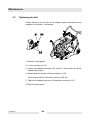
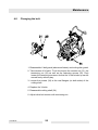
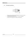
1
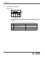
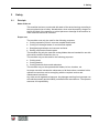
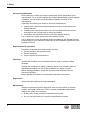
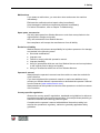
0201438en 005 01.2011 Floor saw BFS 1350AL Operator´s manual Manufacturer Wacker Neuson SE Preußenstraße 41 80809 München www.wackerneuson.com Tel.: +49-(0)89-354 02-0 Fax: +49-(0)89-354 02-390 Translation of the original operator's manual in German Table Of Contents 1. Technical data 27 2. Description 29 2.1 2.2 2.3 2.4 Application ...........................................................................................29 Maximum permissible tilt .....................................................................29 Functional description .........................................................................30 General instructions for use for diamond-edged cutting blades ..........31 3. Transport to the worksite 32 4. Operation 33 4.1 4.2 4.3 4.4 4.5 4.6 4.7 4.8 4.9 4.10 4.11 4.12 5. Adjusting the handle ............................................................................33 Adjusting / Aligning the guide wheel ....................................................33 Cutting depth setting ...........................................................................34 Water tank ...........................................................................................35 Parking brake ......................................................................................36 Assembling the cutting blade ..............................................................37 Disassembling the cutting blade ..........................................................38 Right-hand, left-hand cutting conversion .............................................39 Checking the motor before starting .....................................................40 Starting the engine ..............................................................................41 Operation the engine ...........................................................................43 Switch off the engine ...........................................................................44 Maintenance 5.1 5.2 5.3 5.4 5.5 5.6 5.7 5.8 5.9 45 Maintenance schedule ........................................................................45 Checking engine oil level .....................................................................46 Changing the engine oil .......................................................................46 Cleaning the air cleaner ......................................................................47 Cleaning the filter cup ..........................................................................48 Idle setting ...........................................................................................48 Tightening the belt ...............................................................................49 Changing the belt ................................................................................50 Checking the spark plug ......................................................................51 3 1 Foreword 1 Foreword This operator's manual contains information and procedures for the safe operation and maintenance of your Wacker Neuson machine. In the interest of your own safety and to prevent accidents, you should carefully read through the safety information, familiarize yourself with it and observe it at all times. This operator's manual is not a manual for extensive maintenance and repair work. Such work should be carried out by Wacker Neuson service or authorized specialists. The safety of the operator was one of the most important aspects taken into consideration when this machine was designed. Nevertheless, improper use or incorrect maintenance can pose a risk. Please operate and maintain your Wacker Neuson machine in accordance with the instructions in this operator's manual. Your reward will be troublefree operation and a high degree of availability. Defective machine parts must be replaced immediately! Please contact your Wacker Neuson representative if you have any questions concerning operation or maintenance. All rights reserved, especially reproduction and distribution rights. Copyright 2011 Wacker Neuson SE No part of this publication may be reproduced in any form or by any means, electronic or mechanical, including photocopying, without the expressed written permission of Wacker Neuson. Any type of reproduction, distribution or storage on data media of any type and form not authorized by Wacker Neuson represents an infringement of copyright and will be prosecuted. We expressly reserve the right to make technical modifications – even without special notice – which aim at further improving our machines or their safety standards. 4 2 Introduction 2 2.1 Introduction Means of representation for this operator's manual Warning symbols This operator's manual contains safety information of the categories: DANGER, WARNING, CAUTION, NOTICE. They should be followed to prevent danger to life and limb of the operator or damage to equipment and exclude improper service. DANGER This warning notice indicates immediate hazards that result in serious injury or even death. f Danger can be avoided by the following the actions mentioned. WARNING This warning notice indicates possible hazards that can result in serious injury or even death. f Danger can be avoided by the following the actions mentioned. CAUTION This warning notice indicates possible hazards that can result in minor injury. f Danger can be avoided by the following the actions mentioned. NOTICE This warning notice indicates possible hazards that can result in material damage. f Danger can be avoided by the following the actions mentioned. Notes Note: Complementary information will be displayed here. 5 2 Introduction Instructions f This symbol indicates there is something for you to do. 1. Numbered instructions indicate that you have to carry out something in a defined sequence. 2.2 This symbol is used for lists. Wacker Neuson representative Depending on your country, your Wacker Neuson representative is your Wacker Neuson service, your Wacker Neuson affiliate or your Wacker Neuson dealer. You can find the addresses in the Internet at www.wackerneuson.com. The address of the manufacturer is located at the beginning of this operator's manual. 2.3 Described machine types This operator's manual is valid for different machine types from a product range. Therefore some figures can differ from the actual appearance of your machine. It is also possible that the descriptions include components which are not a part of your machine. Details for the described machine types can be found in the chapter Technical data. 6 2 Introduction 2.4 Identification of the machine Nameplate data The nameplate lists information that uniquely identifies your machine. This information is needed to order spare parts and when requesting additional technical information. f Enter the information of your machine into the following table: Item 7 Designation 1 Group and type 2 Construction year 3 Machine no. 4 Version no. 5 Item no. Your information 3 Safety 3 3.1 Safety Principle State of the art This machine has been constructed with state-of-the-art technology according to the recognized rules of safety. Nevertheless, when used improperly, dangers to the life and limb of the operator or to third persons or damage to the machine or other materials cannot be excluded. Proper use The machine must only be used for the following purposes: Cutting expansion joints in concrete, asphalt and screed. Cutting out damaged areas of concrete and asphalt. Straightening blacktops and concrete surfaces. Sawing off precast concrete parts. The machine may only be used with cutting blades that are intended for use with the machine and the material to be cut. The machine may not be used for the following purposes: Cutting wood. Cutting plastics. Cutting materials that contain asbestos. The machine may not be operated with blades, knives, brushes, etc. Its proper use also includes the observance of all instructions contained in this operator's manual as well as complying with the required service and maintenance instructions. Any other use is regarded as improper. Any damage resulting from improper use will void the warranty and the liability on behalf of the manufacturer. The operator assumes full responsibility. 8 3 Safety Structural modifications Never attempt to modify the machine without the written permission of the manufacturer. To do so will endanger your safety and the safety of other people! In addition, this will void the warranty and the liability on behalf of the manufacturer. Especially the following are cases of structural modifications: Opening the machine and the permanent removal of components from Wacker Neuson. Installing new components which are not from Wacker Neuson and not equivalent to the original parts in design and quality. Installation of accessories which are not from Wacker Neuson. It is no problem to install spare parts from Wacker Neuson. It is no problem to install accessories that are available in the Wacker Neuson product range of your machine. Please refer to the installation regulations in this operator's manual. Requirements for operation The ability to operate the machine safely requires: Proper transport, storage and setup. Careful operation. Careful service and maintenance. Operation Operate the machine only as intended and only when in proper working condition. Operate the machine in a safety-conscious manner with all safety devices attached and enabled. Do not modify or disable any safety devices. Before starting operation, check that all control and safety devices are functioning properly. Never operate the machine in a potentially explosive environment. Supervision Never leave the machine running unattended! Maintenance Regular maintenance work is required in order for the machine to operate properly and reliably over time. Failure to perform adequate maintenance reduces the safety of the machine. 9 Strictly observe the prescribed maintenance intervals. Do not use the machine if it requires maintenance or repairs. 3 Safety Malfunctions If you detect a malfunction, you must shut down and secure the machine immediately. Eliminate the malfunctions that impair safety immediately! Have damaged or defective components replaced immediately! For further information, refer to chapter Troubleshooting. Spare parts, accessories Use only spare parts from Wacker Neuson or such that are equivalent to the original parts in design and quality. Only use accessories from Wacker Neuson. Non-compliance will exempt the manufacturer from all liability. Exclusion of liability Wacker Neuson will refuse to accept liability for injuries to persons or for damage to materials in the following cases: Structural modifications. Improper use. Failure to comply with this operator's manual. Improper handling. Using of spare parts which are not from Wacker Neuson and not equivalent to the original parts in design and quality. Using of accessories which are not from Wacker Neuson. Operator's manual Always keep the operator's manual near the machine or near the worksite for quick reference. If you have misplaced the operator's manual or require an additional copy, contact your Wacker Neuson representative or download the operator's manual from the Internet (www.wackerneuson.com). Always hand over this operator's manual to other operators or to the future owner of the machine. Country-specific regulations Observe the country-specific regulations, standards and guidelines in reference to accident prevention and environmental safety, for example those pertaining to hazardous materials and wearing protective gear. Complement the operator's manual with additional instructions taking into account the operational, regulatory, national or generally applicable safety guidelines. 10 3 Safety Operator's controls Always keep the operator's controls of the machine dry, clean and free of oil or grease. Operating elements such as ON/OFF switch, throttle levers etc. may not be locked, manipulated or changed without authorization. Checking for signs of damage Inspect the machine when it is switched off for any signs of damage at least once per work shift. Do not operate the machine if there is visible damage or defects. Have any damage or defects eliminated immediately. 3.2 Qualification of the operating personnel Operator qualifications Only trained personnel are permitted to start and operate the machine. The following rules also apply: You are at least 18 years of age. You are physically and mentally fit. You have received instruction on how to independently operate the machine. You have received instruction in the proper use of the machine. You are familiar with required safety devices. You are authorized to start machines and systems in accordance with the standards governing safety. Your company or the operator has assigned you to work independently with this machine. Incorrect operation Incorrect operation or misuse by untrained personnel can endanger the health and safety of the operator or third persons and also cause machine and material damage. Operating company responsibilities The operating company must make the operator's manual available to the operator and ensure that the operator has read and understood it. 11 3 Safety Work recommendations Please observe the recommendations below: 3.3 Work only if you are in a good physical condition. Work attentively, particularly as you finish. Do not operate the machine when you are tired. Carry out all work calmly, circumspectly and carefully. Never operate the machine under the influence of alcohol, drugs or medication. This can impair your vision, reactions and your judgment. Work in a manner that does not endanger others. Ensure that no persons or animals are within the danger zone. Protective gear Work clothing Clothing should be appropriate, i.e. should be close-fitting but not restrict your movement. When on construction sites, do not wear long hair loosely, loose clothing or jewelry including rings. These objects can easily get caught or be drawn in by moving machine parts. Only wear clothing made of material that is not easily flammable. Personal protective gear Wear personal protective gear to avoid injuries or health hazards: Non-skid, hard-toed shoes. Work gloves made of durable material. Overalls made of durable material. Hard hat. Ear protection. Face protection. Eye protection. Breathing protection in the case of dusty ambient air. Ear protection This machine generates noise that exceeds the country-specific permissible noise levels (individual rating level). It may therefore be necessary to wear ear protection. You can find the exact value in the chapter Technical Data. When wearing ear protection while working, you must pay attention and exercise caution because your hearing is limited, e.g. in case someone screams or a signal tone sounds. Wacker Neuson recommends that you always wear ear protection. 12 3 Safety Breathing protection If a lot of dust is produced when cutting, always wear suitable breathing protection. Use the water supply. Provision of fire extinguishers Ensure that a fire extinguisher is always to hand on the worksite. Do not exceed the daily usage limit The machine generates noise. Observe the regulations which apply in your country and guidelines concerning the maximum daily service life of the machine. Always wear the prescribed safety clothing. Information about the noise levels produced by the machine can be found in the Technical Data chapter. 3.4 Transport Switching off the machine Before you transport the machine, it must be switched off, and the engine must be given sufficient time to cool down. Emptying the tank Wacker Neuson recommends emptying the fuel tank before transport. Fuel could run out, e.g. if the machine is tilted. Observe the national safety guidelines and the hazardous materials regulations that apply to the respective means of transportation. 13 3 Safety Lifting When lifting the machine, observe the following instructions: Designate a skilled person to guide you for the lifting procedure. You must be able to see or hear this person. Use only suitable and certified hoisting gear, lifting tackle and load-bearing equipment with sufficient lifting capacities. Only use the attachment points described in the operator's manual. Attach the machine securely to the hoisting gear. Ensure that no one is nearby or under the machine. Do not climb onto the machine. Check the lifting strap on the machine for wear and damage. Before lifting, secure (loose) components with the relevant devices. Remove (loose) components before lifting. Remove the tool before lifting. Loading the machine Loading ramps must be able to bear the load and be in a stable position. Make sure that no one can be endangered if the machine slips away or tips over or if machine parts suddenly move upward or downward. Put the operating controls and moving parts in their transport position. Secure the machine with load-securing straps so that it cannot tip over, fall down or slide away. Only use the attachment points described in the operator's manual. Transport vehicle Use only suitable transport vehicles with sufficient load-carrying capacity and suitable tie-down lugs. Transporting the machine Secure the machine on the transport device against tilting, falling or slipping. Only use the lashing points listed in the operating instructions. Also observe the country-specific regulations, standards and guidelines. Restarting Machines, machine parts, accessories or tools that were detached for transport purposes must be re-mounted and fastened before restarting. Only operate in accordance with the operating instructions. 14 3 Safety 3.5 Operating safety Explosible environment Never operate the machine in a potentially explosive environment. Work environment Familiarize yourself with your work environment before you start work. This includes e.g. the following items: Obstacles in the work and traffic area. Load-bearing capacity of the ground. The measures needed to cordon off the construction site from public traffic in particular. The measures needed to secure walls and ceilings. Options available in the event of an accident. Safety in the work area When working with the machine especially pay attention to the following points: Electric lines or pipes in work area. Gas lines or water lines in the work area. Material becoming separated, dropping down or ejected. Make sure that you do not put other persons in danger. Pay maximum attention in the vicinity of drops or slopes. Risk of falling. Maintain a sufficient distance from flammable materials. Checks before starting work Check the following points before beginning work: Condition of cutting blade. Safety devices. Switch and current-carrying lines for damage and corrosion. Tightness of the cutting blade. Machine settings. Starting the machine Observe the safety information and warning notices located on the machine and in the operator's manual. Never attempt to start a machine that requires maintenance or repairs. Start the machine as described in the operator's manual. 15 3 Safety Vertical stability Always ensure that the machine is vertically stable and cannot tip over, roll or slide away. Proper operator position Do not leave the proper operator position while operating the machine. The intended operator position is at the controls behind the machine. Caution with hot parts Do not touch the machine during or shortly after operation. Some parts can become very hot and can cause severe burns. Caution with movable parts Keep your hands, feet and loose clothing away from moving or rotating machine parts. Parts of your body being pulled in or crushed can cause serious injuries. Caution with toxic materials Some materials may contain toxic chemicals which are released during demolition. Therefore personal protective equipment must be worn to prevent inhalation of and skin contact with work dust. No persons endangered Be sure that no persons are endangered by flying or falling materials. Always work very attentively, and anticipate potential hazards. Make sure that people in the vicinity are at a sufficient distance from the machine. Do not use any starter sprays Highly flammable starter sprays pose a fire hazard. Do not use any starter sprays. Starter sprays are highly flammable and can cause backfiring and engine damage. Switching off the machine Switch off the engine in the following situations: Before breaks. If you are not using the machine. Store the machine in such a way that it cannot tilt, fall or slip. 16 3 Safety Storage Store the machine securely so that it cannot tilt, fall or slip. Storage location After operation, allow the machine to cool and then store it in a sealed-off, clean and dry location protected against frost and inaccessible to children. Vibrations When manually operated machines are intensively used, long-term damage caused by vibrations cannot be precluded. Observe the relevant legal instructions and guidelines to minimize vibration stress. Details on vibration stress associated with the machine can be found in the chapter Technical Data. 3.6 Safety during the operation of combustion engines Checking for signs of damage Check the engine while switched off for leaks and cracks in the fuel line, tank and fuel cap at least once per work shift. Do not operate the machine if there is visible damage or defects. Have any damage or defects eliminated immediately. Dangers during operation Combustion engines can be dangerous, particularly during operation and when refueling. Read and follow all safety instructions. Otherwise there is a risk of personal injury and/or damage to property! Do not start the engine near spilt fuel or if you smell fuel – this may cause an explosion! Remove the machine from such areas. Remove the spilt fuel immediately! Do not change the engine speed Do not change the preset engine speed, as this may cause engine damage. You may only change the idle speed. The idle speed must be set such that the cutting blade does not rotate while the engine is idling. 17 3 Safety Preventing fires Open flames and smoking are strictly prohibited in the immediate vicinity of the machine. Make sure that waste, such as paper, dry leaves or grass do not accumulate around the exhaust muffler. The waste materials may ignite. Safety precautions when refueling Please observe the following safety-relevant instructions when refueling: Do not refuel near open flames. Do not smoke. Turn off the engine before refueling and allow it to cool down. Refuel in a well-ventilated environment. Wear fuel-proof protective gloves and, if there is the possibility of spraying, protective goggles and clothing. Do not inhale fuel vapors. Avoid skin and eye contact with fuel. For refueling, use clean tools such as a hopper. Do not spill fuel, especially onto hot parts. Remove any spilt fuel immediately. Use the correct fuel grade. Do not mix fuel with other liquids. Fill the tank only up to the maximum marking. If there is no maximum marking, do not fill up the tank completely. Lock the fuel cap securely after refueling. Operation in closed rooms In closed or partially closed rooms such as tunnels, drifts or deep trenches, ensure sufficient ventilation and extraction by, for example, providing a powerful exhaust air fan. Danger of poisoning! Do not inhale exhaust fumes. They contain toxic carbon monoxide that can lead to unconsciousness or death. Caution with hot parts Do not touch any hot parts such as the engine block or exhaust muffler during operation or directly afterwards. These parts can become very hot and cause severe burns. Shutting off the fuel tap When the machine stops, shut off the fuel tap. 18 3 Safety Cleaning the engine Clean the engine when it is cool to remove any dirt. Do not use gasoline or solvents. Danger of explosion! Health hazard due to exhaust fumes Warning The engine's exhaust fumes contain chemicals which are known to the State of California to cause cancer, congenital defects or other reproductive anomalies. Notes on the EPA engine Caution This machine is equipped with an EPA-certified engine. Modifying the engine speed influences the EPA certification and emission. The engine may only be set by a skilled technician. For more detailed information, contact your nearest engine or Wacker Neuson representative. 3.7 Safety during floor saw operation Belt guard Never operate the machine without a belt guard! Exposed belts and belt pulleys are dangerous and can cause serious injuries if they pull in any part of your body or if parts are ejected. Danger of falling over Operate the machine so that it cannot tip over or fall down from bordered areas, edges and steps. Cutting blade guard Never operate the machine without a cutting blade guard. The cutting blade guard performs the following functions: Protects the operator from the rotating cutting blade. Diverts workpiece particles and sparks or chips from a damaged cutting blade away from the operator. Only operate the machine when the cutting blade guard is folded down. Make sure that the cutting blade guard and its limit stops are not damaged or worn. 19 3 Safety Wet-cutting Use a water sprayer when dust formation is excessive, e.g. when cutting concrete or stone. Only use cutting blades that are suitable for wet cutting. Before ending the wet cutting process, allow the cutting blade to run without the water sprayer until it is dry. Not exceeding the maximum tilt position Do not exceed the maximum tilt position (see the description in the Maximum permissible tilt chapter). Only operate the machine at maximum tilt for short periods of time. If you exceed the maximum tilt, the engine lubrication system will fail and thus inevitably damage important engine parts. Notes regarding work methods Fold down the protective hood fully. The protective hood can catch material flung away from the work area and divert it away from the operator. Particularly when starting the engine you have to make sure that the cutting blade does not come into contact with anything. Always operate the machine at full throttle even when first placing it into the cut. When first placing the the cutting blade into the cut, set it slowly onto the material. Excessive pressure can damage the cutting blade. Move the machine in a straight line together with the cutting blade. Pressure from the side can damage the cutting blade. Avoid cutting tight curves. On sloping carriageways and surfaces, pressure must not be applied to the side of the blade. Never exceed the maximum speed (printed on cutting blade). Removing foreign objects before cutting Before cutting, remove foreign objects such as nails, etc. from the cutting area. Cutting various materials Do not process loose materials (e.g. paving stones). Do not cut into the gravel area using diamond-edged cutting blades. When cutting on the edge of the track or when cutting two different materials (cutting in the joint area), uneven wear is possible. 20 3 Safety Do not touch a rotating cutting blade Never touch a rotating cutting blade with your hand or any other body part. Danger of severe injury. Pay attention and exercise caution when working with ear protection When wearing ear protection you must pay attention and exercise caution because your hearing is limited, e.g. in case someone screams or a signal tone sounds. Danger of fire due to sparks Danger of fire due to hot workpiece particles flung away from the work area. Do not work near flammable materials. Only wear clothing made of material that is not easily flammable. Notes regarding cutting blades 21 The cutting blade must be suitable for use with the cut-off saw. The cutting blade must be suitable for the material to be cut. The speed allowed for the cutting blade must be the same as or higher than the maximum machine spindle speed. Mount the cutting blade such that its rotation direction is the same as that of the machine. Only use cutting blades with permissible cutting blade diameters. When using cutting blades with a hole diameter greater than the machine shaft, use the suitable adapter ring. Only use undamaged cutting blades. Ensure that you also follow the instructions of the cutting blade manufacturer. Do not use cutting blades that have fallen. Change the cutting blade only when the engine has been turned off. Always tighten the cutting blade with the specified torque. Test the new cutting blade for approx. 1 min at maximum speed (without cutting). Only use cutting blades with use-by dates that have not expired. When storing cutting blades, always lay them flat in an area that is protected from frost. 3 Safety 3.8 Maintenance Maintenance work Service and maintenance work must only be carried out to the extent described in these operating instructions. All other procedures must be performed by your Wacker Neuson representative. For further information, refer to chapter Maintenance. It is not permitted to tilt the machine for maintenance work. Switching off the engine Before carrying out care or maintenance work, switch off the engine and allow it to cool down. For gasoline powered engines, you must pull off the spark plug cap. Checking the ignition system Caution: the electronic ignition generates a very high voltage. Disconnecting the battery For machines with electric starter, you must disconnect the battery before working on the electronic parts. Working on the battery Always take the following safety measures when working with the battery: No fire, sparks, or smoking while working with batteries. Batteries contain corrosive acid. Use acid-proof protective gloves and protective goggles when working with batteries. Avoid short circuits due to improper connection or bypassing with tools. Disconnect the negative terminal first when disconnecting the battery. Connect the positive terminal first when connecting the battery. Re-fasten terminal covers after connecting the battery. 22 3 Safety Handling operating fluids safely Observe the following points when handling operating fluids, e.g. fuels, oils, greases, coolants etc.: Always wear personal safety clothing. Avoid skin and eye contact with operating fluids. Do not inhale or swallow operating fluids. In particular, avoid contact with hot operating fluids. Burn and scalding hazard. Dispose of replaced or spilled operating fluids according to the applicable regulations for environmental protection. If operating fluids escape from the machine, cease operation of the machine and have it repaired immediately by your Wacker Neuson representative. Assembling safety devices If it was necessary to dismantle safety devices, they must be reassembled and checked immediately after completing maintenance work. Always tighten loosened screw connections, complying with prescribed starting torque. Cleaning Always keep the machine clean and be sure to clean it each time you have finished using it. Do not use gasoline or solvents. Danger of explosion! Do not use high pressure washers. Permeating water can damage the machine. When electrical equipment is present, this can pose a serious injury risk from electric shocks. 23 3 Safety 3.9 Safety devices WARNING Danger of injury due to open moving parts. f Only operate the machine with properly installed and functioning safety devices. f Do not modify or remove safety devices. Item 1 Designation Cutting blade guard Cutting blade guard Never operate the machine without a cutting blade guard. The cutting blade guard performs the following functions: Protects the operator from the rotating cutting blade. Diverts workpiece particles and sparks or chips from a damaged cutting blade away from the operator. Only operate the machine when the cutting blade guard is folded down. 24 4 Safety and information labels 4 Safety and information labels Your machine has adhesive labels containing the most important instructions and safety information. Make sure that all the labels are kept legible. Replace any missing or illegible labels. The item numbers for the labels are in the parts book. 25 4 Safety and information labels 2 1 Label Description 0125778 Item Start-Stop. 0219259 2 Caution, risk of injury Read the operator's manual. Wear a eye protection and ear protection! Machine may not be offset with the cutting blade rotating. Schnellaushubhebel. 4 Central suspension. 0219357 3 Cutting depth setting. SES 360° = 5 mm 6 7 0058870 5 Guaranteed sound power level. US machines Warning. WARNING WARNUNG ADVERTENCIA 0219261 ADVERTISSEMENT 0219176 26 1. Technical data Item no. Length x Width x Height Weight mm (in): kg (lb): Power transmission BFS 1350AL BFS 1350L BFS 1350ALS 0008898 0610398 0008936 0008885 0610399 1085 x 604 x 1052 (42.7 x 23.78 x 41.4) 136 (300) mm (in): 500 (20) Min. diameter of blade mm (in): 350 (14) Max. cutting width mm (in): 12 (0.47) Location bore mm (in): 25,4 (1) cm (in): 18,5 (0.73) m/s (ft/s): m/s (ft/s): m/s (ft/s): m/s (ft/s): 40,3 (132) 46,1 (151) 51,8 (170) 57,6 (189) Disc’s circumferential speed ø 350 ø 400 ø 450 ø 500 (at engine’s nominal speed) No-load revolutions of disc (at engine’s nominal speed) 1/min: 2200 Water tank capacity l (gal): 28 (7.40) Drive motor Air-colled single-cylinder 4 stroke gasoline engine Piston displacement cm3: (cm3): Rated speed 1/min: Nominal output (*) kW: 389 404 389 3600 9,6 Fuel Fuel consumption (at engine’s nominal speed) 153 (337) From drive engine via drive belt to cutting blade Max. diameter of blade Max. cutting depth 9,9 9,6 Normal or lead-free gasoline l/h: (gal/h): 4,3 (1.14) 4,2 (1.11) 4,3 (1.14) Fuel tank capacity l (gal): 6,1 (1.59) 7,0 (1.85) 6,1 (1.61) Lubricant oil capacity l (gal): 1,1 (0.29) 1,2 (0.32) 1,1 (0.29) SAE 10W30 API SJ SAE 10W30 API SE SAE 10W30 API SJ – – 12 V- 18 Ah Oil specification Battery TD00673GB.fm 134 (295) 27 Spark plug Type: BFS 1350AL BFS 1350L BFS 1350ALS NGK BPR6ES / Denso W20EPR-U NGK BP6ES / Champion N9Y NGK BPR6ES / Denso W20EPR-U (*) In accordance with the installed useful outlet power according to Directive 2000/14/EG. TD00673GB.fm Sound pressure level at operator’s station LPA: The weighted effective acceleration value, determined according to EN ISO 5349 m/s2: Uncertainty K m/s2: 28 98 dB(A) 97 dB(A) 98 dB(A) 6,9 6,7 6,9 1,5 Description 1. Description 1.1 Application ∗ Cutting expansion joints in concrete and asphalt surfaces. ∗ Repair work on streets, e.g. cutting out damaged areas in asphalt and concrete. ∗ Straightening blacktops and concrete surfaces. ∗ For demolition jobs and refurbishment of old buildings. ∗ Sawing off precast concrete parts. ∗ Expansion joints and installation channels in floors. ∗ Laying induction loops and cables in signal installations. 1.2 Maximum permissible tilt The maximum permissible tilt applies to the engine level. T01134GB.fm 29 Description 1.3 Functional description The floor saw must only be operated in a forward direction (see arrow). The drive motor (2) attached to the frame drives the cutting blade via the belt (7). The cutting blade can be infinitely adjusted by means of a crank handle (5), 1 turn corresponds to a cutting depth adjustment of 5 mm. At any time it is also possible to remove or introduce the cutting blade into the material to be cut by way of the lever (3). The cutting blade guard (1) can be swiveled upwards to make it easier to assemble and disassemble the cutting blade. Furthermore, the cutting blade guard can be connected with the water tank by means of a hose and an adapter. Wetting the cutting blade with water prevents dust from developing. A parking brake (6) has been included in the lower, right section of the console. The brake guarantees a safe parking of the floor saw on upward or downward slopes or gradients. The engine works according to the 4-stroke principle, is started by means of a recoil starter , takes in the air via a dry air filter and is air colled. T01134GB.fm 30 Description The revs on the engine can be infinitely varied using the throttle control lever (4); the optimum cutting speed of the blade is only achieved with the engine working at full load. In order to facilitate the starting, the eingine is provieded with a choke. 1.4 General instructions for use for diamond-edged cutting blades ∗ Never use a cutting blade with a larger diameter than necessary in order to cut a certain depth. ∗ If the cutting blade comes to a standstill, remove it from the cut before starting the machine again. If the cutting blade comes to a standstill in the cut, check whether the belt is tightened adequately. Check the tension screw and make sure that it is tightened properly. ∗ Cut in a straight line. Mark the cutting line clearly in such a way that the operational personnel can follow it easily. This is to ensure that the floor saw machine does not need to be redirected from one side to the other (avoid cutting tight curves). ∗ Sufficient drive power is essential! When cutting, work at full throttle. ∗ Caution on steep tracks and levels! The machine must not exert lateral force against the blade. ∗ Never exceed the maximum speeds (imprinted on cutting blade)! ∗ Use a suitable diamond-edged cutting blade for the material to be cut (asphalt, concrete ...). Wacker Neuson offers an extensive range of diamondedged cutting blades in different qualities. ∗ Do not cut into the gravel area using diamond-edged cutting blades. When cutting on the edge of the track or when cutting two different materials (cutting in the joint area), uneven wear is possible. Check carefully for irregularities (reinforcements etc.) in the material to be processed. These can overload the cutting blade very quickly. When starting cutting operations, work carefully and with a low down speed. ∗ Do not process loose materials (e. g. paving stones). T01134GB.fm 31 Transport to the worksite 2. Transport to the worksite Requirements: ∗ When transporting the floor saw, use only suitable hoisting gear with a minimum load-bearing capacity of 200 kg. ∗ Always turn off the motor during transportation! ∗ Empty the water tank! ∗ Remove the cutting blade prior to transport. Set the lowest cutting position on the floor saw. ∗ Attach appropriate secure lifting devices to the central lifting point (10) provided for this purpose. ∗ If you transport the floor saw on the cargo area of a vehicle, strap it down securely on the special safety bar. ∗ Fold the guide wheel to the top and the handles to the front (or the stirrup handle to the top). ∗ Apply the parking brake. ∗ Handles, guide wheel and other operating controls must not be used as attachment points. Note: Also observe the regulations in the chapter Safety information. T01135GB.fm 32 Operation 3. Operation 3.1 Adjusting the handle The width and height of the handles can be adjusted according to the use and the body height of the operator. To do this, release the clamping lever (11) and apply it in the new position. 3.2 Adjusting / Aligning the guide wheel 3.2.1 Adjusting the guide wheel The guide wheel is designed to help the operator in making long, straight cuts. The guide wheel can be exactly adjusted to the cutting blade by loosening the jam nut (1) and turning the screw (2). T01136GB.fm 33 Operation 3.2.2 Aligning the guide wheel To do this, make a cut of approx. 2 m length on a flat surface and with the minimum cutting depth. Then pull back the machine without lateral force. Then you can align the guide wheel exactly with the cut. 3.3 Cutting depth setting Place the quick-lift lever in the forward lock-in position; this will enable you to exactly adjust the cutting depth by turning the crank (5). One turn of the crank drops the cutting disc by 5 mm (cutting depth). It is possible to choose between two lock-in positions of the quick-liftlever (3) at any time: 1. The forward lock-in position allows cutting with an individually set cutting depth. 2. The cutting disc is never engaged in the material when the quick-lift lever is in the back lock-in position. The floor saw can now be easily moved from one working area to the next. 3.3.1 Operation of the quick-lift lever: 1. Loosen lock with the guide handle (13) and press down T-handle. 2. Push T-handle all the way forwards or, as the case may be, backwards. 3. Let go of T-handle. The handle will lock automatically. Each floor saw has been equipped with a metric and an inch scale; the scale is matched with the respective standard cutting disc. T01136GB.fm 34 Operation 3.3.2 To set the scale proceed as follows: 1. Push quick-lift lever (3) fully forwards. 2. Turn the cutting depth crank (5) until the cutting disc barely starts touching the floor. 3. Loosen the screws (14) and move the arrow until it coincides with the ”0” mark of the scale. 4. Retighten the screws (14). 3.4 Water tank The floor saw features an integrated, removable water tank (15). The filler opening (16) can be found at top left side. The amount of water can be regulated or stopped (17). To remove the water tank proceed as follows: 1. Empty the water tank completely if required. For this purpose open the metering tap (17) completely. 2. Release the hose coupling (18) once the tank has been completely drained. 3. Turn hand crank (5) to a horizontal position. 4. Apply the parking brake (6). 5. Pull the tank out by the recessed grip (20). T01136GB.fm 35 Operation The adjustable hose coupling (19) can be used as a feeder point (1/2inch) for an external hose connection. 3.5 Parking brake To apply the parking brake (6) push bolt (21) towards the right until it locks in the spokes of the back wheel. Always place the machine on a flat, level and non-skid surface. The maximum grade should not exceed 10°. T01136GB.fm 36 Operation 3.6 Assembling the cutting blade 3.6.1 Checking a new cutting blade: ∗ The blade type must be suitable for the material to be cut. Observe the peripheral speed, refer to the "Technical data"! ∗ The arbor diameter of the cutting blade must precisely fit the shaft to ensure smooth blade running. ∗ The cutting blade must be undamaged. Observe the correct direction of rotation of the cutting blade! That means the rotational direction mark on the cutting blade must correspond with the rotational direction mark on the cutting blade guard. 3.6.2 T01136GB.fm Proceed as follows for the assembly of the cutting blade: 1 Fold up the cutting blade guard (1). 2 Prior to the assembly of the cutting blade, clean the spring washers and the locking pin and check them for damage. 37 Operation 3. Place an intermediate layer (disc label) under each faceplate when using bakelite-bonded cutting discs. 4. Attach cutting blade and spring washer on the shaft. 5. Tighten the hexagonal bolt firmly. To do this, apply counter pressure on the spanner surfaces of the cutting shaft. Note: To assemble cutting disc on right side tighten nut in anticlockwise direction (left-handed thread). To assemble cutting disc on left side tighten nut in clockwise direction. 6. Fold down the cutting blade guard. The flange cover must be in place on the protective hood. 7. Connect the water hose. Starting the machine is only permitted with a water hose connected and the water supply turned on. 3.7 Disassembling the cutting blade 3.7.1 T01136GB.fm Proceed as follows for the disassembly of the cutting blade: 1. Raise the cutting disc guard (1) all the way up. 2. Apply parking brake (6), stop engine (23) and stop water supply (17). 3. Move quick-lift lever (3) to position at the rear. 38 Operation 4. Disconnect the water hose. 5. Fold up the cutting blade guard (1). 6. Loosen the tightening nut. Hold cutting shaft with spanner at spanner surfaces. 7. Fold down the cutting blade guard. Note: To disassemble cutting disc from right side loosen nut in clockwise direction (left-handed thread). To disassemble cutting disc from left side loosen nut in anticlockwise direction. 3.8 Right-hand, left-hand cutting conversion To switch the cutting blade from one side to the other proceed as follows: 1. Disassemble the water hose fasteners and then reassemble on the opposite side in each case. 2. Loosen screws (24), remove cutting disc guard (1) and protective hood (22). 3. Loosen screws (25) and then reassemble covering plates (26) on the opposite sides. 4. Reassemble cutting disc guard (1) and protective hood (22) on the required sides. T01136GB.fm 39 Operation Note: Carry out the following additional conversions if needed: 3.9 ∗ Loosen screws (27), turn guide wheel around and then reassemble screws (27). ∗ Loosen screws (28), turn around dirt catcher and then reassemble screws (28). Checking the motor before starting 3.9.1 Engine oil Switch off the engine. Prior to checking the engine oil level or refilling engine oil, make sure that the engine bolting level is aligned horizontally. ∗ Remove the oil filler cap (oil level indicator). ∗ If the oil level is below the lower filling mark on the dip stick, add suitable engine oil until the oil reaches the edge of the filler neck. ∗ An oil change is required if the engine oil is dirty. ∗ Only use high-quality engine oil, see Technical Data. The engine is automatically switched off when the oil level falls below a specific level. If this is the case, the engine can only be started after engine oil has been refilled. 3.9.2 Fuel Do not smoke during refueling and make sure that there are no open flames or sparks in the immediate vicinity. Turn off the engine and open the fuel tank cap. ∗ Only use leadfree fuel. ∗ Close the fuel tap before the fuel tank is filled with fuel. ∗ Always use the fuel filter when refilling fuel. ∗ Wipe off any spilled fuel before starting the engine. 3.9.3 Air filter system Check to see that the air filter inserts and the cyclone housing are clean and undamaged. Clean and replace inserts if necessary. T01136GB.fm 40 Operation 3.10 Starting the engine The cutting blade must not be in contact with the ground. 1. Open the fuel tap. 2. Move the choke lever to the CLOSE positio. . Note: If the engine is warm or the air temperature is high, move the control lever away from the Choke postion as soon as the engine starts. T01136GB.fm 3. Push throttle lever (4) slightly forward. 4. Turn main switch (23) to position ”1”. 41 Operation 5. Pull starter handle out slowly until a slight resistance is felt, then pull handle with strength. Caution: Do not allow the starter grip to snap back against the engine. Return it dently to grevent damage to the starter. T01136GB.fm 42 Operation 3.11 Operation the engine As the engine warms up, gradually move the choke lever to the OPEN position. Set required engine speed with throttle lever (4) 3.11.1 Oil Alert system The Oil Alert system is designed to prevent engine damage caused by an insufficient amount of oil in the crankcase. Before the oil level in the crankcase. Before the oil level in the crankcase can fall below a safe limit, the Oil Alert system will automatically shut down the engine (leave the main switch in position ”1”). T01136GB.fm 43 Operation 3.12 Switch off the engine To turn off the engine in the event of an emergency, switch the main switch (1) to "0". Under normal circumstances, proceed as follows: T01136GB.fm 1. Pull the throttle lever (4) all the way back to the stop position. 2. Turn the main switch (23) to the position ”0”. 3. Close the fuel tap. 44 Maintenance 4. Maintenance 4.1 Maintenance schedule Component Machine Maintenance work Check for signs of damage and wear – change, if necessary the components. Safety devices Before operation Main switch Check for proper functioning – change, if necessary. Air cleaner - Check for external damage and a tight fit. - Check foam and filter element – clean or replace, if necessary. Fuel - Check the tank cap for leakage – change, if necessary. - Check the fuel level – add fuel as needed. Drive motor Monitoring of: - Excessive vibrations, operating noise. - Engine oil and fuel leaks. Engine oil Check the oil level – add oil as needed. Miscellaneous - Check the cutting blade for damage and tightness – replace or tighten, if necessary. - Check the direction of rotation arrow of the cutting blade. - Check that the height adjustment moves freely. - Check the water supply. Engine oil Initial oil change. Air cleaner Clean – change, if necessary. Belt Check tension and wear – change, if necessary. Spark plug Clean, set electrode gap 0.7-0.8 mm. Engine oil Change. Fuel filter Have this replaced by Wacker Neuson service. Spark protection Clean. Filter cup Clean. Idle setting Check idle setting – set if necessary. Spark plug Change. Air cleaner Change. Valve clearance Have this repaired by Wacker Neuson service. T01137GB.fm Maintenance interval 8 hours (daily) 20 hours 50 hours (weekly) 100 hours (monthly) 100 hours (twice a year) 300 hours (annually) 45 Maintenance 4.2 4.3 Checking engine oil level ∗ Turn off the engine. ∗ Align the engine bolting level horizontally. ∗ Remove any dirt around the oil level dipstick. ∗ Remove the oil level dipstick and wipe it with a clean, lint-free cloth. ∗ Screw the oil level dipstick all the way back in and pull it out again. ∗ Check: The motor oil level must be between the lower and upper marks. ∗ If necessary, pour new engine oil into the opening until the upper mark is reached on the oil level dipstick (see chapter Technical data for oil type). ∗ Screw in the oil level dipstick and tighten it by hand. Changing the engine oil The work area should be covered with a waterproof sheet to protect the floor (protection of the environment). ∗ Align the engine bolting level horizontally. ∗ Bring the engine to a hand warm temperature, either by letting it cool down or running it until it is warm. ∗ Turn off the engine. ∗ Place a sufficiently large container under the oil drain hose to catch the used oil. ∗ Remove oil drain hose from the holder. ∗ Remove any dirt around the locking screw. ∗ Unscrew the cap nut. ∗ Let the used oil drain out completely. Avoid spilling oil. Remove any spilled oil immediately. ∗ Close oil drain hose with cap nut. ∗ Attach oil drain hose to the holder. ∗ Pour new engine oil (see chapter Technical data) into the opening of the oil level dipstick until the upper mark is reached on the oil level dipstick (see Checking engine oil level). ∗ Screw in the oil level dipstick and tighten it by hand. Dispose of the used oil in accordance with the applicable regulations. T01137GB.fm 46 Maintenance 4.4 Cleaning the air cleaner A dirty air cleaner obstructs the flow of air to the carburetor. To prevent carburetor malfunctions, clean the air cleaner on a regular basis. Clean the filter more frequently if the engine is operated in an extremely dusty environment. Warning: Never use gasoline or cleaning solutions with a low flash point to clean the air cleaner cartridge. This could cause a fire or worse an explosion. Caution: Never run the engine without an air cleaner. This leads to undue engine wear. 1 Remove the wing nuts and the air cleaner cap. Take out the elements and separate them. Check both elements for holes or tears and replace them as needed. 2 Foam element: Wash out the element in warm soap water, rinse it and allow it to completely dry. If necessary, wash out the element in a cleaning solution with high flash point and allow it to dry. 3 Paper element: Tap the element lightly against a hard surface a few times to loosen excess dirt. Never attempt to brush off the dirt, since this will rub the dirt into the fibers. Replace the paper element if it is very dirty. Cleaning the cyclone housing: If dirt accumulates in the cyclone housing, unscrew the three special flat head screws and wipe the components or rinse them with water. Then completely dry off the components and assemble them carefully. Caution: T01137GB.fm ∗ During the reassembly of the cyclone, make sure that the cloth of the air inlet fits properly into the groove of the preliminary filter cap. ∗ Install the air horn in the correct direction. 47 Maintenance 4.5 Cleaning the filter cup Close the fuel tap. Remove the filter cup with the o-ring and wash it out with non-combustible and low-flammable solvent. Allow it to completely dry, then reinstall it and tighten it firmly. Open the fuel tap and check for leaks. 4.6 Idle setting ∗ Start the engine and let it warm up to its normal operating temperature. 2 Idle speed limiting screw ∗ T01137GB.fm Adjust the idle speed limiting screw while the engine is running in order to reach the prescribed idle speed. Prescribed idle speed: 1,400 ± 150 rpm. 48 Maintenance 4.7 Tightening the belt Check the belt in the course of the weekly engine maintenance and retighten it as follows, if necessary:: 1. Remove V-belt guard. 2. Loosen counter nut (31). 3. Loosen the fastening screws (32) until the V-belt’s take-up can be shifted without play. 4. Adjust drive belt tension with tensioning nut (33). V-belt tension 600 N (vibration frequency 104 Hz). 5. Tighten the fastening screws (32) and the counter nut (31). 6. Mount the belt guard. T01137GB.fm 49 Maintenance 4.8 Changing the belt 1. Disassemble V-belt guard (above and below) and cutting disc guard. 2. Take tension off V-belts. To do this loosen the counter nut (31), the tensioning nut (33) as well as the fastening screws (32). Only loosen the fastening screws so far that the V-belt’s take-up can be moved freely without play. 3. Loosen the screws (34) at the oval flanges (on both sides) of the cutting shaft. 4. Replace the V-belts. 5. Reassemble cutting shaft (34). 6. Adjust drive belt tension with tensioning nut. T01137GB.fm 50 Maintenance 4.9 Checking the spark plug 0,7 - 0,8 mm ∗ Remove any soot deposits from the electrodes of the spark plug using a spark plug cleaner or a wire brush. ∗ Check the spark plug gap and set it to 0.7 - 0.8 mm, if necessary. ∗ Select the correct spark plug, see chapter Technical Data. T01137GB.fm 51 5 Troubleshooting 5 Troubleshooting Potential faults, their causes and remedies can be found in the following table. Notify your Wacker Neuson representative in case of malfunctions you cannot or may not remedy yourself. Malfunction Cause Remedy Engine does not start. The main switch is in the "0" position. Set the main switch to the "I" position. Fuel tap is closed. Open the fuel tap. Fuel tank is empty. Top up with fuel. Fuel line is clogged. Have the fuel line cleaned. * Fuel filter is clogged. Have the fuel filter replaces. * Carburetor is clogged. Have the carburetor cleaned. * Air cleaner is clogged. Clean or replace air cleaner. Spark plug cap is defective. Have the machine repaired. * Spark plug is defective. Change the spark plug. Spark plug is loose. Tighten the spark plug. Spark plug gap is set incorrectly. Set the spark plug gap. Insufficient engine oil. Top up with engine oil. Idle speed is adjusted incorrectly. Set idle speed. Fuel tank is empty. Top up with fuel. Fuel filter is clogged. Have the fuel filter replaces. * Air cleaner is dirty. Clean or replace air cleaner. Insufficient engine oil. Top up with engine oil. Engine has low performance. Air cleaner is dirty. Clean or replace air cleaner. Recoil starter defective. Starter rope jammed. Have the starter rope replaced. * Engine shuts off right after starting. Starter rope torn off. * Cutting blade does not rotate. The belt is faulty. Replace the belt. Engine cannot be turned off. Electrical connection of the main switch is defective. 1. Close the fuel tap. The engine will switch off after a few seconds. 2. Have the machine repaired.* Have these tasks carried out by the service department of your Wacker Neuson contact person. 52 6 Emission control systems information and warranty 6 Emission control systems information and warranty The Emission Control Warranty and associated information is valid only for the U.S.A., its territories, and Canada. Emission control systems warranty statement See the engine owner’s manual for the applicable exhaust and evaporative emission warranty statement. 53 Operator´s manual 7 Glossary 7 7.1 Glossary Use of oxygenated fuels Some conventional gasolines are blended with alcohol. These gasolines are collectively referred to as oxygenated fuels. If you use an oxygenated fuel, be sure it is unleaded and meets the minimum octane rating requirement. Before using an oxygenated fuel, confirm the fuel's contents. Some states / Provinces require this information to be posted on the fuel pump. The following are Wacker Neuson approved percentages of oxygenates: Ethanol - (ethyl or grain alcohol) 10% by volume. You may use gasoline containing up to 10% ethanol by volume (commonly referred to as E10). Gasoline containing more than 10% ethanol (such as E15, E20, or E85) may not be used because it could damage the engine. Methanol - (methyl or wood alcohol) 5% by volume. You may use gasoline containing up to 5% methanol by volume, as long as it contains cosolvents and corrosion inhibitors to protect the fuel system. Gasoline containing more than 5% methanol by volume may cause starting and/or performance problems. It may also damage metal, rubber, and plastic parts of your fuel system. If you notice any undesirable operating symptoms, try another service station, or switch to another brand of gasoline. Fuel system damage or performance problems resulting from the use of an oxygenated fuel containing more than the percentages of oxygenates mentioned above are not covered under warranty. 54 EC Declaration of Conformity Manufacturer Wacker Neuson SE, Preußenstraße 41, 80809 München Product Type BFS 1345 Product type BFS 1350 Floor saw Item no. 0008764, 0610141, 0610142, 0610242 0008885, 0008898 Installed power output kW 9,6 Measured sound power level dB(A) 106 Guaranteed sound power level dB(A) 107 Conformity assessment procedure acc. to 2000/14/EC, Appendix V. Guidelines and standards This is to certify that this product meets and complies with the relevant regulations and requirements of the following guidelines and standards: 98/37/EC, from 29.12.2009: 2006/42/EC, 2000/14/EC, 2004/108/EC, EN 55012:2007 Authorized person for technical documents: Axel Häret Munich, 24.08.2009 Franz Beierlein Head of product management Dr. Michael Fischer Head of Research and Development www.wackerneuson.com