1
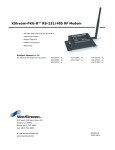
9XTend-PKG-R™ RS-232/485 RF Modem
9XTend-PKG-R RF Modem
Interfacing Protocol
Modem Operation
Modem Configuration
RF Communication Modes
Appendices
Product Manual v1.2.4
For MaxStream part numbers:
XT09-PK…-R…
1 Watt Transmit Power, -110 dBm Receiver Sensitivity, 256-bit AES Encryption
355 south, 520 west, suite 180
Lindon, UT 84042
Phone: (801) 765-9885
Fax: (801) 765-9895
[email protected]
M100171
www.maxstream.net (live chat support)
2005.08.02
9XTend‐PKG‐R™ RS‐232/485 RF Modem – Product Manual v1.2.4 © 2005 MaxStream, Inc. All rights reserved
No part of the contents of this manual may be transmitted or reproduced in any form or by any means without the written permission of MaxStream, Inc. XTend™ and 9XTend‐PKG‐R™ are registered trademarks of MaxStream, Inc. AES Encryption Source Code © 2005 Dr. Brian Gladman, Worcester, UK. All rights reserved. Conditions: ‐ Distributions of AES source code include the above copyright notice, this list of conditions and disclaimer. ‐ Distributions in binary form include the above copyright notice, this list of conditions and disclaimer in the documentation and/or other associated materials. ‐ The copyright holderʹs name is not used to endorse products built using this software without specific written permission. Alternatively, provided that this notice is retained in full, this product may be distributed under the terms of the GNU General Public License (GPL), in which case the provisions of the GPL apply INSTEAD OF those given above. Disclaimer ‐ This AES software is provided ʹas isʹ with no explicit or implied warranties in respect of its properties, including, but not limited to, correctness and/or fitness for purpose. Technical Support:
Phone: (801) 765-9885
Live Chat: www.maxstream.net
E-Mail: [email protected]
© 2005 MaxStream, Inc. Confidential and Proprietary ii 9XTend‐PKG‐R™ RS‐232/485 RF Modem – Product Manual v1.2.4 Contents 1. 9XTend-PKG-R™ RF Modem
4
1.1. Features Overview 4
1.1.1. Worldwide Acceptance 4
5.2. Streaming Mode 42
5.2.1. Connection Sequence 42
1.2.1. Specifications 5
5.3. Acknowledged Mode 43
1.3. XTend-PKG-R Interface 6
5.3.1. Connection Sequence 43
7
2.1. RS-232 Operation 7
5.4. Multi-Transmit Mode 45
5.4.1. Connection Sequence 45
Appendix A: Agency Certifications
2.1.1. DIP Switch Settings & Pin Signals 7
2.1.2. Wiring Diagrams 8
46
FCC Certification 46
2.2. RS-485 (2-wire) Operation 9
Labeling Requirements 46
2.2.1. DIP Switch Settings & Pin Signals 9
FCC Notices 46
2.2.2. Wiring Diagram 9
FCC-Approved Antennas (900 MHz)
2.3. RS-485 (4-wire) & RS-422 Operation 10
48
IC (Industry Canada) Certification 50
2.3.1. DIP Switch Settings & Pin Signals 10
Appendix B: Development Guide
2.3.2. Wiring Diagrams 10
51
RS-232 Accessories Kit Contents 51
2.3.3. RS-485/422 Connection Guidelines 11
3. Modem Operation
41
5.1. Addressing Options 41
1.2. Product Overview 5
2. Interfacing Protocol
5. RF Communication Modes
12
3.1. Serial Communications 12
Adapters 52
Antennas 53
Appendix C: Additional Information
3.1.1. RS-232 and RS-485/422 Data Flow 12
54
1 Year Warranty 54
3.1.2. Host and RF Modem Settings 12
Ordering Information 54
3.1.3. Flow Control 13
Contact MaxStream 55
3.2. Modes of Operation 14
3.2.1. Idle Mode 14
3.2.2. Transmit Mode 14
3.2.3. Receive Mode 16
3.2.4. Sleep Mode 17
3.2.5. Shutdown 17
3.2.6. Command Mode 18
4. Modem Configuration
20
4.1. Automatic DIP Switch Configurations 20
4.2. Programming Examples 21
4.2.1. AT Commands (Using X-CTU Software)
21
4.2.2. Binary Commands 22
4.3. Command Reference 23
4.4. Command Descriptions 24
© 2005 MaxStream, Inc. Confidential and Proprietary iii 9XTend‐PKG‐R™ RS‐232/485 RF Modem – Product Manual v1.2.4 1. 9XTend‐PKG‐R™ RF Modem The 900 MHz XTend RF Modem is MaxStream’s longest range drop-in
wireless solution. Out-of-box, the RF modem is equipped to sustain
long range wireless links between devices. Simply enter serial data into
one modem and the data surfaces on the other end of the wireless link.
The modem transfers a standard asynchronous serial data stream
between two or more modems. Its built-in RS-232, RS-485 and RS-422
interface allows for rapid integration into existing data systems.
1.1. Features Overview
Long Range at a Low Cost
Easy-to-Use
1 Watt Power Output (1 mW – 1 W, selectable)
No configuration required
Range (@ 9600 bps throughput data rate):
Advanced configurations available
through AT & binary Commands
•
Indoor/Urban: up to 3000’ (900 m)
•
Outdoor line-of-sight:
up to 14 miles (22 km) w/ dipole antenna
•
Outdoor line-of-sight:
up to 40 miles (64 km) w/ high gain antenna
Range (@ 115200 bps throughput data rate):
•
Indoor/Urban: up to 1500’ (450 m)
•
Outdoor line-of-sight:
up to 7 miles (11 km) w/ dipole antenna
•
Outdoor line-of-sight:
up to 20 miles (32 km) w/ high gain antenna
Receiver Sensitivity: -110 dBm (@ 9600 baud),
–100 dBm (@ 115200 baud)
Advanced Networking & Security
True Peer-to-Peer (no “master” required),
Point-to-Point, Point-to-Multipoint & Multidrop
Retries and Acknowledgements
External DIP Switch configurations
7 to 28 V power supply
Continuous RF data stream of up to
115.2 kbps
Transparent Operation – Wireless links
replace serial wires
Software-selectable serial interfacing
MODBUS,
I/O Support
,
,
&
XII™ Interference Immunity
Power-saving Sleep Modes
Streaming, Acknowledged & MultiSend RF Communication Options
Free & Unlimited Technical Support
FHSS (Frequency Hopping Spread Spectrum)
10 hopping channels - each with over 65,000 network addresses available
256-bit AES Encryption (Refer to KY Command [p29] to implement)
1.1.1. Worldwide Acceptance
FCC Approved (USA - Go to Appendix A [p46] for FCC Requirements)
Systems that contain XTend Modems inherit MaxStream’s FCC Certification
IC Approved (Canada)
ISM (Industrial, Scientific & Medical) license-free 902-928 MHz frequency band
Manufactured under ISO 9001:2000 registered standards
© 2005 MaxStream, Inc. Confidential and Proprietary 4 9XTend‐PKG‐R™ RS‐232/485 RF Modem – Product Manual v1.2.4 1.2. Product Overview
The XTend-PKG-R RF Modem comes configured to provide immediate long range wireless links
between devices. The RF modem can be configured for additional functionality through the use of
standard AT and binary commands [Refer to the Command Mode [p18] & Modem Configuration
[p20] sections for programming options].
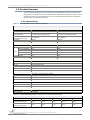
1.2.1. Specifications
Table 1‐01. XTend‐PKG‐R RS‐232/485 RF Modem Specifications XTend-PKG-R 900 MHz RF Modem Specifications
Performance
@ 9600 bps Throughput Data Rate
@ 115200 bps Throughput Data Rate
Transmit Power Output
Indoor/Urban Range
Outdoor
RF line-of-sight Range
Interface Data Rate
(selectable using BD Command)
RF Data Rate
Receiver Sensitivity
1 mW - 1 W (software selectable)
Up to 3000’ (900 m)
Up to 14 miles (22 km) w/ dipole antenna
Up to 40 miles (64 km) w/ high-gain antenna
1 mW - 1 W (software selectable)
Up to 1500’ (450 m)
Up to 7 miles (11 km) w/ dipole antenna
Up to 20 miles (32 km) w/ high-gain antenna
1200 - 230400 bps
1200 - 230400 bps
10000 bps
-110 dBm
125000 bps
-100 dBm
Power Requirements (refer also to Table 1-02 below)
Receive Current
110 mA
16 sec cyclic sleep (SM=8) 20 mA
8 sec cyclic sleep (SM=7) 21 mA
Idle
Currents 4 sec cyclic sleep (SM=6) 24 mA
2 sec cyclic sleep (SM=5) 30 mA
1 sec cyclic sleep (SM=4) 39 mA
Pin Sleep Power Down
17 mA
Serial Port Sleep Power Down
45 mA
110 mA
19 mA
19 mA
20 mA
22 mA
25 mA
17 mA
45 mA
Networking & Security
Frequency
RF Transmission
Modulation
Supported Network Topologies
Channel Capacity
Encryption
902-928 MHz ISM Band
FHSS (Frequency Hopping Spread Spectrum)
FSK (Frequency Shift Keying)
Peer-to-Peer, Point-to-Point, Point-to-Multipoint & Multidrop
10 hop sequences share 50 frequencies
256-bit AES Encryption – Refer to KY Command [p29] to implement
Physical Properties
Size
Weight
Serial Connector
Operating Temperature
2.750” x 5.500” x 1.125” (6.99cm x 13.97” x 2.86cm)
7.1 oz. (200g)
DB-9
-40 to 85º C (industrial)
Antenna
Connector
Type
Impedance
RPSMA (Reverse-polarity SMA)
½ wave dipole whip, 6.75” (17.15 cm), 2.1 dBi Gain
50 ohms unbalanced
Certifications (visit www.maxstream.net for complete list)
FCC Part 15.247
OUR-9XTEND
Industry Canada (IC)
4214A-9XTEND
Table 1‐02. XTend RF Modem Specifications – Relative to user‐selected TX Power Output Power Requirements (TX currents relative to each TX Power Output option)
Transmit Power Output
Transmit Current @9600 baud
(9 VDC supply voltage, typical)
Transmit Current @115K baud
(9 VDC supply voltage, typical)
1 mW
10 mW
100 mW
500 mW
1W
110 mA
145 mA
250 mA
510 mA
900 mA
110 mA
140 mA
245 mA
500 mA
800 mA
© 2005 MaxStream, Inc. Confidential and Proprietary 5 9XTend‐PKG‐R™ RS‐232/485 RF Modem – Product Manual v1.2.4 1.3. XTend-PKG-R Interface
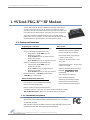
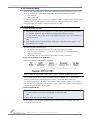
1-01a. Config (Configuration) Switch
The Configuration Switch provides an alternate method for
entering into Command Mode. To enter Command Mode at the
default RF data rate of the RF modem, depress the Config
Switch for two seconds.
Figure 1‐01. Front View 1-01b. I/O & Power LEDs
LEDs indicate modem activity as follows:
1‐01c. Serial Port 1‐01d. RSSI LEDs Yellow (top LED) = Serial Data Out (to host)
Green (middle) = Serial Data In (from host)
Red (bottom)
= Power/TX Indicator (Red light is on
when powered and pulses off briefly during RF transmission)
1‐01b. I/O & Power LEDs 1‐01e. Power Connector* 1-01c. Serial Port
Standard female DB-9 (RS-232) DCE connector – Connector can be
also used for RS-485 and RS-422 connections.
1‐01a. Config Switch 1-01d. RSSI LEDs
* Note: The XTend RF Modem can accept voltages as low as 5 (±5%) V. Contact MaxStream technical support (801) 765‐9885 to implement this option. RSSI LEDs indicate the amount of fade margin present in an active
wireless link. Fade margin is the difference between the incoming
signal strength and the modem’s receiver sensitivity.
3
2
1
0
LEDs ON
LEDs ON
LED ON
LED ON
=
=
=
=
Very Strong Signal (> 30 dB fade margin)
Strong Signal (> 20 dB fade margin)
Moderate Signal (> 10 dB fade margin)
Weak Signal (< 10 dB fade margin)
1-01e. Power Connector *
7-28 VDC Power Connector.
1-02a. DIP Switch
During the power-on sequence, the DIP Switch automatically
configures the XTend Modem to operate in different modes.
Each time the RF modem is powered-on, intelligence inside the
XTend RF Modem programs the modem according to the
positions of the DIP Switch. [Refer to Figure 1-03 for DIP
Switch settings].
Figure 1‐02. Back View 1-02b. Antenna Port
1‐02a. DIP Switch 1‐02b. Antenna Port Port is a 50Ω RF signal connector for connecting to an external
antenna. The connector type is RPSMA (Reverse Polarity SMA)
female. The connector has threads on the outside of a barrel and a
male center conductor.
Figure 1‐03. DIP Switch Settings Refer to table in the “Automatic DIP Switch Configurations” section [p20] for information about configurations triggered by the DIP Switch. © 2005 MaxStream, Inc. Confidential and Proprietary 6 9XTend‐PKG‐R™ RS‐232/485 RF Modem – Product Manual v1.2.4 2. Interfacing Protocol The XTend-PKG-R RF Modem supports the following interfacing protocols:
•
RS-232
•
RS-485 (2-wire) Half-Duplex
•
RS-485 (4-wire) and RS-422
2.1. RS-232 Operation
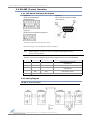
2.1.1. DIP Switch Settings & Pin Signals
Figure 2‐01. RS‐232 DIP Switch Settings Figure 2‐02. Pins used on the female RS‐232 (DB‐9) Serial Connector DIP Switch settings are read and applied only while powering‐on. Table 2‐01. RS‐232 Signals and their implementations on the XTend RF Modem (Low‐asserted signals are distinguished by horizontal line over pin name.) DB-9 Pin
RS-232
Name
Pin
Reference
Name*
Description
Implementation
1
DCD
GPO2 /
RX LED
Data-Carrier-Detect
Connected to DSR (pin6)
2
RXD
DO
Received Data
Serial data exiting the RF Modem (to host)
3
TXD
DI
Transmitted Data
Serial data entering into the RF modem (from host)
4
DTR
GPI2 / SLEEP
Data-Terminal-Ready
Can enable POWER-DOWN on the RF Modem
5
GND
-
Ground Signal
Ground
DSR
GPO2 /
RX LED
Data-Set-Ready
Connected to DCD (pin1)
Request-to-Send
flow control or
Provides
enables “Command Mode” on the RF Modem
6
7
/ CMD
8
9
RI
GPI1 /
CMD
/
GPO1 /
/
RS-485 TX EN
Clear-to-Send
-
Ring Indicator
Provides
flow control
Optional power input that is connected internally to the
positive lead of the front power connector
* The Pin Reference Name provides an associative tag that references commands used to define pin behavior. GPI stands for “General Purpose Input” and GPO stands for “General Purpose Output”. For example, the CD Command is used to define the behavior of GPIO2 (pin 1). © 2005 MaxStream, Inc. Confidential and Proprietary 7 9XTend‐PKG‐R™ RS‐232/485 RF Modem – Product Manual v1.2.4 2.1.2. Wiring Diagrams
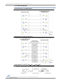
RS-232 DTE Device to a DCE RF Modem
Figure 2‐03. RS‐232 DTE (male connector) device wired to an XTend RF Modem (female connector) DCE RF Modem to an RS-232 DCE Device
Figure 2‐04. XTend RF Modem (female connector) wired to an RS‐232 DTE (male connector) device Sample Wireless Connection: DTE Ù DCE
DCE Ù DCE
Figure 2‐05. Typical wireless connection used for serial communications between DTE and DCE devices © 2005 MaxStream, Inc. Confidential and Proprietary 8 9XTend‐PKG‐R™ RS‐232/485 RF Modem – Product Manual v1.2.4 2.2. RS-485 (2-wire) Operation
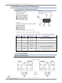
2.2.1. DIP Switch Settings & Pin Signals
Figure 2‐06. RS‐485 (2‐wire) Half‐Duplex DIP Switch Settings Figure 2‐07. Pins used on the female RS‐232 (DB‐9) Serial Connector Figure 2‐08. RS‐485 (2‐wire) with Termination (optional) Termination is the 120 Ω resistor between T+ and T‐. DIP Switch settings are read and applied only while powering‐on. Note:
Refer to Figures 2-15 and 2-16 for RJ-45 connector pin designations used in
RS-485/422 environments.
Table 2‐02. RS‐485 (2‐wire half‐duplex) Signals and their implementations on the XTend RF Modem DB-9 Pin
RS-485 Name
Description
Implementation
Transmit serial data to and from the
XTend RF Modem
2
T/R- (TRA)
Negative Data Line
5
GND
Ground Signal
Ground
8
T/R+ (TRB)
Positive Data Line
Transmit serial data to and from the
XTend RF Modem
9
PWR
Power
Optional power input that is connected internally
to the front power connector
1, 3, 4, 6, 7
not used
2.2.2. Wiring Diagram
RS-485 (2-wire) Half-Duplex
Figure 2‐09. XTend RF Modem in an RS‐485 (2‐wire) half‐duplex environment © 2005 MaxStream, Inc. Confidential and Proprietary 9 9XTend‐PKG‐R™ RS‐232/485 RF Modem – Product Manual v1.2.4 2.3. RS-485 (4-wire) & RS-422 Operation
2.3.1. DIP Switch Settings & Pin Signals
Figure 2.10. RS‐485 (4‐wire) and RS‐422 DIP Switch Settings Figure 2.12. RS‐485 (4‐wire) & RS‐422 with Termination (optional) Figure 2.11. Pins used on the female RS‐232 (DB‐9) Serial Connector Termination is the 120 Ω resistor between T+ and T‐. DIP Switch settings are read and applied only while powering‐on. Table 2‐03. RS‐485/422 (4‐wire) Signals and their implementations with the XTend‐PKG‐R RF Modem DB-9 Pin
RS-485/422
Name
Description
Implementation
2
T- (TA)
Transmit Negative
Data Line
Serial data sent from the XTend RF Modem
3
R- (RA)
Receive Negative
Data Line
Serial data received by the XTend RF Modem
5
GND
Signal Ground
Ground
7
R+ (RB)
Receive Positive
Data Line
Serial data received by the XTend RF Modem
8
T+ (TB)
Transmit Positive
Data Line
Serial data sent from the XTend RF Modem
9
PWR
Power
Optional power input that is connected internally
to the front power connector
1, 4, 6
not used
2.3.2. Wiring Diagrams
RS-485 (4-wire) Half-Duplex
Figure 2‐13. XTend RF Modem in an RS‐485 (4‐wire) environment © 2005 MaxStream, Inc. Confidential and Proprietary 10 9XTend‐PKG‐R™ RS‐232/485 RF Modem – Product Manual v1.2.4 RS-422
Figure 2‐14. XTend RF Modem in an RS‐485 (4‐wire) environment 2.3.3. RS-485/422 Connection Guidelines
The RS-485/422 protocol provides a solution for wired communications that can tolerate high
noise and push signals over long cable lengths. RS-485/422 signals can communicate as far as
4000 feet (1200 m). RS-232 signals are suitable for cable distances up to 100 feet (30.5 m).
RS-485 offers multi-drop capability in which up to 32 nodes can be connected. The RS-422
protocol is used for point-to-point communications.
Suggestions for integrating the XTend Modem with the RS-485/422 protocol:
1.
When using Ethernet twisted pair cabling: Select wires so that T+ and T- are connected to
each wire in a twisted pair. Likewise, select wires so that R+ and R- are connected to a
twisted pair. (For example, tie the green and white/green wires to T+ and T-.)
2.
For straight-through Ethernet cable (not cross-over cable) – The following wiring pattern
works well: Pin3 to T+, Pin4 to R+, Pin5 to R-, Pin6 to T-
3.
Note that the connecting cable only requires 4 wires (even though there are 8 wires).
4.
When using phone cabling (RJ-11) – Pin2 in the cable maps to Pin3 on opposite end of cable
and Pin1 maps to Pin4 respectively.
Figure 2‐15. Male DB‐9 to RJ‐45 Adapter (yellow) Figure 2‐16. Female DB‐9 to RJ‐45 Adapter (green) An XTend RF Modem Accessories Kit is available that includes connectors that facilitate RS-485/422
and other serial communications. Refer to the Development Guide in Appendix B for information
concerning the connectors and tools included in the kit.
© 2005 MaxStream, Inc. Confidential and Proprietary 11 9XTend‐PKG‐R™ RS‐232/485 RF Modem – Product Manual v1.2.4 3. Modem Operation WARNING: When operating at 1 Watt power output, observe a minimum separation distance of 2’ (0.6 m) between modems.
Transmitting in close proximity of other modems can damage modem front ends.
3.1. Serial Communications
3.1.1. RS-232 and RS-485/422 Data Flow
The XTend-PKG-R RF Modem interfaces to a host device through a standard RS-232 (DB-9)
connector. Devices that have a standard RS-232 serial port can connect directly through the pins
of the XTend RF Modem as shown in the figure below.
Figure 3‐01. System Data Flow in an RS‐232 environment 3.1.2. Host and RF Modem Settings
Serial communications between a host and an XTend RF Modem are dependent upon having
matching baud rate, parity, stop bit & number of data bits settings. Refer to the table below to
ensure host serial port settings match those of the XTend RF Modem.
Table 3‐01. Parameter values critical to serial communications between the RF Modem and host Parameter Setting
XTend RF Modem Default Parameter Value
Baud (Serial Data Rate)
9600 bps
(BR parameter = 3)
Number of Data Bits
8
(NB parameter = 0)
Parity
None
(NB parameter = 0)
Number of Stop Bits
1
(NB parameter = 0)
Both the XTend RF Modem and host (PC) settings can be viewed and adjusted using MaxStream’s
proprietary X-CTU Software. Use the “Terminal” or “Modem Configuration” tabs to configure the
RF Modem settings. Use the “PC Settings” tab to configure host settings. Refer to the Advanced
Programming and X-CTU Software sections for more information.
© 2005 MaxStream, Inc. Confidential and Proprietary 12 9XTend‐PKG‐R™ RS‐232/485 RF Modem – Product Manual v1.2.4 3.1.3. Flow Control
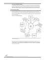
Figure 3‐02. Internal Data Flow Diagram DI (Data In) Buffer and Flow Control
When serial data enters the XTend Modem through the DI Pin, the data is stored in the DI Buffer
until it can be transmitted.
When the RB and RO parameter thresholds are satisfied (refer to Transmit Mode section [p14] for
more information), the modem attempts to initialize an RF connection. If the modem is already
receiving RF data, the serial data is stored in the modem’s DI Buffer. The DI buffer stores at least
2.1 KB. If the DI buffer becomes full, hardware or software flow control must be implemented in
order to prevent overflow (loss of data between the host and XTend Modem).
How to eliminate the need for flow control:
1.
Send messages that are smaller than the DI buffer size. The size of the DI buffer varies
according to the packet size (PK parameter) and the parity setting (NB parameter) used.
2.
Interface at a lower baud rate (BD parameter) than the RF data rate (BR parameter).
Two cases in which the DI Buffer may become full and possibly overflow:
1.
If the serial interface data rate is set higher than the RF data rate of the modem, the modem
will receive data from the host faster than it can transmit the data over-the-air.
2.
If the modem is receiving a continuous stream of RF data or if the modem is monitoring data
on a network, any serial data that arrives on the DI pin is placed in the DI Buffer. The data in
the DI buffer will be transmitted over-the-air when the modem no longer detects RF data in
the network.
Hardware Flow Control (
). When the DI buffer is 17 bytes away from being full; by
to signal to the host device to stop sending data [refer
default, the modem de-asserts (high)
is reto FT (Flow Control Threshold, p28) and CS (GPO1 Configuration, p26) Commands.].
asserted after the DI Buffer has 34 bytes of memory available.
Software Flow Control (XON). XON/XOFF software flow control can be enabled using the FL
(Software Flow Control) Command [p27]. This option only works with ASCII data.
DO (Data Out) Buffer & Flow Control
When RF data is received, the data enters the DO buffer and is sent out the serial port to a host
device. Once the DO Buffer reaches capacity, any additional incoming RF data is lost. The DO
buffer stores at least 2.1 KB.
Two cases in which the DO Buffer may become full and possibly overflow:
1.
If the RF data rate is set higher than the interface data rate of the modem, the modem will
receive data from the transmitting modem faster than it can send the data to the host.
2.
If the host does not allow the modem to transmit data out from the DO buffer because of
being held off by hardware or software flow control.
Hardware Flow Control (
). If
is enabled for flow control (RT Parameter = 2, p35), data
is de-asserted.
will not be sent out the DO Buffer as long as
Software Flow Control (XOFF). XON/XOFF software flow control can be enabled using the FL
(Software Flow Control) Command [p27]. This option only works with ASCII data.
© 2005 MaxStream, Inc. Confidential and Proprietary 13 9XTend‐PKG‐R™ RS‐232/485 RF Modem – Product Manual v1.2.4 3.2. Modes of Operation
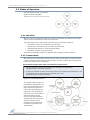
XTend RF Modems operate in five modes.
Figure 3‐03. Modes of Operation The RF modem can only be in one mode at a time. 3.2.1. Idle Mode
When not receiving or transmitting data, the modem is in Idle Mode. The modem uses the same
amount of power in Idle Mode as it does in Receive Mode.
The modem shifts into the other modes of operation under the following conditions:
•
Serial data is received in the DI Buffer (Transmit Mode)
•
Valid RF data is received through the antenna (Receive Mode)
•
Command Mode Sequence is issued (Command Mode)
•
Sleep Mode condition is met (Sleep Mode)
The modem automatically transitions to Idle Mode after responding to these conditions.
3.2.2. Transmit Mode
When the first byte of serial data is received from the host in the DI buffer, the modem attempts
to shift to Transmit Mode and initiate an RF connection with other modems. After transmission is
finished, the modem returns to Idle Mode.
RF transmission begins after either of the following criteria is met:
1.
RB bytes have been received by the host and are pending for RF transmission.
[RB (Packetization Threshold) Command]
2.
At least one character has been received by the host and is pending for RF transmission, and
RO character times of silence have been observed on the host.
[RO (Packetization Timeout) Command]
Figure 3‐04. Transmit Mode Data Flow The character timeout trigger can
be disabled by setting RO to zero.
In this case, transmission will not
begin until RB bytes have been
received and are pending for RF
transmission. The RB parameter
may be set to any value between 1
and the RF packet size (PK),
inclusive. Note that transition to
Transmit Mode cannot take place
during RF reception; the RF
reception must complete before
the modem can transition into
Transmit Mode.
© 2005 MaxStream, Inc. Confidential and Proprietary 14 9XTend‐PKG‐R™ RS‐232/485 RF Modem – Product Manual v1.2.4 After either of the RB and RO conditions are met, the modem then initializes a communications
channel. Serial data in the DI buffer is grouped into RF packets (up to 2048 bytes in each packet
- refer to PK (Maximum RF Packet Size) Command), converted to RF data and then is transmitted
over-the-air until the DI buffer is empty.
Channel initialization is the process of sending an RF initializer that synchronizes receiving
modems with the transmitting modem. During channel initialization, incoming serial data
accumulates in the DI buffer.
RF data, which includes the payload data, follows the RF initializer. The payload includes up to
the maximum packet size (PK Command) bytes. As the TX modem nears the end of the
transmission, it inspects the DI buffer to see if more data exists to be transmitted. This could be
the case if more than PK bytes were originally pending in the DI buffer or if more bytes arrived
from the host during transmission. If more data is pending, the transmitting modem instructs all
listening modems that a subsequent packet is coming. Receiving modems move to the new
frequency and listen for the subsequent packet.
Refer to the RF Communication Options [p41] section for information and state diagrams that
illustrate channel initialization and the sequence of events that follow.
RF Packet
Figure 3‐05. RF Packet Components * When streaming multiple RF packets, the RF Initializer is only sent in front of the first packet. RF Initializer
An RF initializer is sent each time a new connection sequence begins. The RF initializer contains
channel information that notifies receiving modems of information such as the hopping pattern
used by the transmitting modem. Channel initialization takes 5 ms at the 115k RF data rate and
54 ms at the 9600 RF data rate. The first transmission always sends an RF initializer.
An RF initializer can be of various lengths depending on the amount of time determined to be
required to prepare a receiving modem. For example, a wake-up initializer is a type of RF
initializer used to wake remote modems from Sleep Mode (Refer to the FH, LH, HT and SM
Commands for more information). The length of the wake-up initializer should be longer than the
length of time remote modems are in cyclic sleep.
Header
The header contains network addressing information that filters incoming RF data. The receiving
modem checks for matching a Hopping Channel, VID and Destination Address. Data that does not
pass through all three network security layers is discarded.
Figure 3‐06. Network Layers Contained in the Header © 2005 MaxStream, Inc. Confidential and Proprietary 15 9XTend‐PKG‐R™ RS‐232/485 RF Modem – Product Manual v1.2.4 CRC (Cyclic Redundancy Check)
To verify data integrity and provide built-in error checking, a 16-bit CRC (Cyclic Redundancy
Check) is computed for the transmitted data and attached to the end of each RF packet before
transmission. On the receiving end, the receiving modem computes the CRC on all incoming RF
data. Received data that has an invalid CRC is discarded [Refer to the Receive Mode section].
3.2.3. Receive Mode
If a modem detects RF data while in Idle Mode, the modem transitions into Receive Mode to start
receiving RF packets. Once a packet is received, it goes through the receiving end of a CRC
(cyclic redundancy check) to ensure that the data was transmitted without error. If the CRC data
bits on the incoming packet are invalid, the packet is discarded. If the CRC is valid, the packet is
placed the DO Buffer.
Figure 3‐07. Receive Mode Data Flow * Refer to the Addressing Options section (under the RF Communication Options chapter) for more information about address recognition. The modem returns to Idle Mode after valid RF data is no longer detected or after an error is
detected within the received RF data. If serial data is stored in the DI buffer while the modem is
in Receive Mode, the serial data will be transmitted after the modem is finished receiving data
and returns to Idle Mode.
© 2005 MaxStream, Inc. Confidential and Proprietary 16 9XTend‐PKG‐R™ RS‐232/485 RF Modem – Product Manual v1.2.4 3.2.4. Sleep Mode
Software Sleep
Sleep Modes enable the XTend Modem to operate at minimal power consumption when not in
use. Three Sleep Mode options are available:
•
Host Controlled (Pin Sleep)
•
Wake on Serial Port activity (Serial Port Sleep)
•
Wake on RF activity (Cyclic Sleep)
For the modem to transition into Sleep Mode, SM (Sleep Mode) Parameter must have a non-zero
value and one of the following must occur:
1.
The modem is idle (no data transmission or reception) for a user-defined period of time [See
ST (Time before Sleep) Command]
[OR]
2.
GPI2 pin is asserted [GPI2 is equivalent to DTR (Data-Terminal-Ready) under RS-232
operation. Refer to the RS-232 Operation [p7] section for more information.]
While in Sleep Mode, the modem will not transmit or receive data until the modem first shifts
back to Idle Mode. The return to Idle Mode is triggered by the de-assertion of GPI2 or the arrival
of a serial byte through the DI pin. Sleep Mode is enabled and disabled using SM Command.
Table 3‐02. Summary of Sleep Mode Configurations Sleep Mode
Setting
Pin Sleep
(SM=1)
Serial Port Sleep
(SM=2)
Cyclic Sleep
(SM=4-8)
Transition into
Sleep Mode
Host can shut down and
wake modems. Assert GPI2
(SLEEP) pin.
Note: The module will
complete a transmission or
reception before activating
Pin Sleep.
Automatic transition into
Sleep Mode after userdefined period of inactivity
(no transmitting or
receiving). Period of
inactivity set using ST
Command.
Transition out of
Sleep Mode
Related
Commands
Power
Consumption
De-Assert GPI2 (SLEEP)
pin.
SM
Typically 17 mA
When serial byte is received
SM, ST
on the DI pin.
Transitions into and out of Sleep Mode in cycles (userselectable wake-up interval of time set by SM Command).
The Cyclic Sleep interval time must be shorter than “WakeHT, LH, PW, SM, ST
up Initializer Timer” (set by LH Command).
(Can be forced into Idle Mode using GPI2 (SLEEP) pin if
PW (Pin Wake-up) Command is issued.)
Typically 45 mA
Typically 25 mA
(when sleeping, SM=4 ,
1 sec, @120K baud)
For more information about Sleep Modes, refer to the individual commands listed in “Related Commands” column of the table. SM Command is the best starting point. 3.2.5. Shutdown
Hardware Sleep
Shutdown Mode offers the lowest power mode available to MaxStream modem users (< 1 µA).
This mode is not supported by the stand-alone XTend RF Modem, but is available through the
OEM RF Module that is mounted inside the stand-alone XTend RF Modem.
Contact MaxStream Technical Support for more information.
© 2005 MaxStream, Inc. Confidential and Proprietary 17 9XTend‐PKG‐R™ RS‐232/485 RF Modem – Product Manual v1.2.4 3.2.6. Command Mode
To set or read modem parameters; the modem must first enter Command Mode (a state in which
incoming characters are interpreted as commands). Two command types are available:
•
AT Commands
•
Binary Commands
For modified parameter values to persist in the modem’s registry, changes must be saved to nonvolatile memory using WR (Write) Command. Otherwise, parameters are reset to previously
stored values after the modem is powered off and then on again.
AT Command Mode
To enter AT Command Mode:
1.
Send the 3-character command sequence “+++” and observe guard times before and after
the command characters. [See “Default AT Command Mode Sequence” below.]
Use the “Terminal” tab (or other serial communications software) of the X-CTU Software to
enter the sequence.
[OR]
2.
Force entrance into AT Command Mode by keeping the configuration switch [Figure 1-01a,
p6] pressed for two seconds.
Default AT Command Mode Sequence:
•
No characters sent for one second [see BT (Guard Time Before) Command]
•
Input three plus characters (“+++”) within one second [see CC (Command Sequence
Character) Command.]
•
No characters sent for one second [see AT (Guard Time After) Command.]
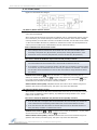
To Send AT Commands to the RF Modem:
Figure 3‐08. Syntax for sending XTend AT Commands NOTE: To read a current parameter value stored in a register, leave the parameter field blank.
The preceding example would change the modem Destination Address “1F”. To store the new
value to the modem’s non-volatile (long term) memory, use the WR (Write) Command.
The “Modem Configuration” tab of the X-CTU Software [p22] provides a software user interface
that facilitates the programming of RF modems. A more in depth look at modem programming is
in the Advanced Configuration section [p20].
To Exit Command Mode:
1.
If no valid AT Commands are received within the time specified by CT (Command Mode
Timeout) Command, the modem automatically returns to Idle Mode.
[OR]
2.
Send ATCN (Exit Command Mode) Command.
For an example on that illustrates programming the modem using AT Commands, refer to the
‘Terminal tab’ section on p21.
© 2005 MaxStream, Inc. Confidential and Proprietary 18 9XTend‐PKG‐R™ RS‐232/485 RF Modem – Product Manual v1.2.4 Binary Command Mode
Sending and receiving parameter values using binary commands is the fastest way to change the
operating parameters of the XTend RF Modem. Binary commands are used most often to sample
signal strength (DB parameter) and/or error counts; or change modem addresses and channels
for polling data systems. Since the sending and receiving of parameter values takes place
through the same serial data path as 'live' data (received RF payload), interference between the
two data types can be a concern.
Common questions about using binary commands:
• What are the implications of asserting CMD while live data is being sent or received?
• After sending serial data, is there a minimum time delay before CMD can be asserted?
• Is a delay required after CMD is de-asserted before payload data can be sent?
• How does one discern between live data and data received in response to a command?
The CMD pin must be asserted in order to send binary commands to the RF modem. The CMD pin
can be asserted to recognize binary commands anytime during the transmission or reception of
data. The status of the CMD signal is only checked at the end of the stop bit as the byte is shifted
into the serial port. The application does not allow control over when data is received, except by
waiting for dead time between bursts of communication.
If the command is sent in the middle of a stream of payload data to be transmitted, the
command will essentially be executed in the order it is received. If the radio is continuously
receiving data, the radio will wait for a break in the received data before executing the command.
signal will frame the response coming from the binary command request [Figure 3-09].
The
A minimum time delay of 100 µs (after the stop bit of the command byte has been sent) must be
observed before the CMD pin can be de-asserted. The command executes after all parameters
associated with the command have been sent. If all parameters are not received within 0.5
seconds, the modem returns to Idle Mode.
Note: When parameters are sent, they are two bytes long with the least significant byte sent first.
Binary commands that return one parameter byte must be written with two parameter bytes.
Refer to p22 for a binary programming example.
Commands can be queried for their current value by sending the command logically ORed (bitwise) with the value 0x80 (hexadecimal) with CMD asserted. When the binary value is sent (with
no parameters), the current value of the command parameter is sent back through the DO pin.
Figure 3‐09. Binary Command Write then Read Signal #4 is CMD Signal #1 is the DIN signal to the modem Signal #2 is the DOUT signal from the modem Signal #3 is In this graph, a value was written to a register and then read out to verify it. While not in the middle of other received data, note that the signal outlines the data response out of the modem. IMPORTANT:
For the XTend Modem to recognize binary commands, the RT (GPI1 Configuration)
parameter must be set to one. If binary programming is not enabled (RT != 1), the
modem will not recognize the data as binary commands.
© 2005 MaxStream, Inc. Confidential and Proprietary 19 9XTend‐PKG‐R™ RS‐232/485 RF Modem – Product Manual v1.2.4 4. Modem Configuration 4.1. Automatic DIP Switch Configurations
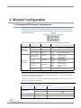
Each time an RF Modem is powered on, AT commands are sent to the on-board RF module as
dictated by the positions of the DIP switches. DIP switch configurations are sent automatically
during the power-on sequence and affect modem parameter values as shown in the table below.
Figure 4‐01. DIP Switches Table 4‐01. Power‐up Options ‐ Commands sent as result of DIP Switch Settings (SW = DIP Switch) Switches
Switches 1 & 2
(Restore Defaults /
Serial Interfacing)
Switches 5 & 6
(TX/RX Modes)
Condition
Behavior
Commands Sent During Power-up
If SW1 & SW2
are ON (up)
Restore Defaults
ATRE
ATWR
(Restore Defaults)
(Write defaults to non-volatile memory)
If SW1 is ON (up)
RS-232 Operation
ATCS 0
(RS-232, CTS flow control)
If SW1 is OFF (down)
RS-485/422
Operation
ATCS 3
(RS-485 or RS-422 Operation)
If SW5 is ON (up) &
SW6 is OFF (down)
Peer-to-Peer
If SW5 & SW6 are
OFF (down)
Multipoint Base
If SW5 is OFF (down) &
SW6 is ON (up)
Multipoint Remote
If SW5 is ON (up) &
SW6 is ON (up)
User Defined
ATAM
(Auto-set MY, MY = unique)
ATDT FFFF
(Destination Address)
ATMT 3
(Multi-Transmit option)
ATMY 0
(Source Address)
ATDT FFFF
(Destination Address)
ATMT 3
(Multi-Transmit option)
ATAM
(Auto-set MY, MY = unique)
ATDT 0
(Destination Address)
ATMT 0
(Multi-Transmit option)
ATRR A
(Retries)
Processor is disabled and AT Commands are not sent to
the modem (except for CS command as shown below.)
IMPORTANT: To avoid overwriting previously stored custom configurations (due to the automatic
configurations that take place each time the RF modem is powered-on), it is necessary to disable a
processor located inside the RF modem.
To disable the processor, turn switches 5 and 6 ON (up). When switches 5 and 6 are ON, only the CS
command is sent [refer to table below].
Table 4‐02. User Defined Mode (Switches 5 and 6 are ON (up)) DIP Switches ON (up)
Condition
Command Sent During Power-up
If CS = 0, 1, 2 or 4
CS parameter remains the same
If CS = 3
ATCS 0
(RS-232 operation,
SW2, SW5 and SW6
If CS = 2
ATCS 2
(GPO1 high)
SW5 and SW6 only
If CS = 0, 1, 2, 3 or 4
ATCS 3
(RS-485/422 Operation)
SW1, SW5 and SW6
© 2005 MaxStream, Inc. Confidential and Proprietary flow control)
20 9XTend‐PKG‐R™ RS‐232/485 RF Modem – Product Manual v1.2.4 4.2. Programming Examples
For information about entering and exiting AT and Binary Command Modes, refer to the
Command Mode section [p18].
4.2.1. AT Commands (Using X-CTU Software)
MaxStream has provided X-CTU software for programming the modem using an extensive list of
AT Commands. The X-CTU software provides an interface that is divided into four tabs that
facilitate the following functions:
•
PC Settings tab - Setup PC serial port to interface with an XTend RF Modem
•
Range Test tab – Test XTend RF Modem's range in varying environments
•
Terminal tab – Configure and read XTend RF Modem parameters using AT Commands
•
Modem Configuration tab – Configure and read RF Modem parameters
To install the X-CTU Software:
Double-click the ‘setup_X-CTU.exe’ file that is located on the MaxStream CD and under the
‘Downloads’ section of the following web page: www.maxstream.net/helpdesk/. Then follow the
prompts of the installation screens.
PC Settings tab
As stated in the Serial Communications section [p12]; in order to communicate data to the RF
modem through the PC, baud (serial data rate), data bit, parity and stop bit settings on the PC
serial port must match those of the RF modem. The ‘PC Settings’ tab provides a software user
interface that facilitates the modification of PC serial port setting.
PC Setup
1.
Set the DIP Switch to RS-232 mode. Switch 1 is ON (up) and the remaining 5 switches are
OFF (down).
2.
Connect the male DB-9 connector of the PC with the female DB-9 connector of the RF
modem using an RS-232 cable.
3.
Power the RF modem through the power connector.
4.
Go to the PC Settings tab and select parameter values from the dropdown lists that match
the current parameter values of the RF modem.
Figure 4‐02. Setup for RF Modem Configurations through X‐CTU Software Terminal tab
A terminal program has been built into the X-CTU software and is located under the ‘Terminal’
tab. The Terminal tab provides an easy-to-use interface for programming the modem.
Multiple AT Commands. Multiple AT commands can be entered on one line with one carriage
return at the end of the line. Each command must be delimited by a comma (spaces in between
are optional). The “AT” prefix is only sent before the first command and should not be included
with subsequent commands in a line.
System Response. When a command is sent to the modem, the modem will parse and execute
the command. Upon successful execution of a command, the modem returns an “OK” message. If
execution of a command results in an error, the modem returns an “ERROR” message.
© 2005 MaxStream, Inc. Confidential and Proprietary 21 9XTend‐PKG‐R™ RS‐232/485 RF Modem – Product Manual v1.2.4 EXAMPLE: Restore RF Modem Default Parameters using the Terminal tab:
Note: Do not send commands to the module during flash programming (when parameters are being written to the module registry). Wait for the ʺOKʺ system response that follows the ATWR command before entering the next command or use flow control. Example: Both of the following examples restore the XTend Modem’s factory defaults and save
the parameters to non-volatile memory.
Method 1 (One line per command)
Issue AT Command
+++
ATRE <Enter>
ATWR <Enter>
ATCN <Enter>
System Response
OK<CR> (Enter into AT Command Mode)
OK<CR> (Restore modem default parameter values)
OK<CR> (Write new values to non-volatile memory)
OK<CR> (Exit AT Command Mode)
Method 2 (Multiple commands on one line)
Issue AT Command
+++
ATRE, WR <Enter>
ATCN <Enter>
System Response
OK<CR> (Enter into AT Command Mode)
OK<CR> (Execute multiple commands)
OK (Exit AT Command Mode)
NOTE: Default parameter values of the RF Modem can also be restored by selecting the ‘Restore’
button located on the Modem Configuration tab [refer to the example below].
Modem Configuration tab
The ‘Modem Configuration’ tab of the X-CTU software can be used to activate advanced functions.
EXAMPLE: Read & Restore Default Parameters using the Modem Configuration tab:
The following steps show how to read currently stored modem parameter values; then restore
the modem parameters to their factory-default states.
1.
Open the X-CTU program (Start --> Programs --> MaxStream --> X-CTU):
2.
Under the “PC Settings” tab, select the PC Serial Com Port from the dropdown list that will be
used to connect to the RF Modem.
3.
Select a "Baud rate" to match the default RF data rate of the RF Modem. Use default values
for all other fields.
4.
Select the “Modem Configuration” tab.
5
Select the ‘Read’ button to read currently stored parameter values of the modem.
6.
Select the ‘Restore’ button to restore factory-default parameter values.
7.
Select the ‘Write’ button to save default values to non-volatile memory.
4.2.2. Binary Commands
To Send Binary Commands:
Example: Use binary commands to change the RF modem’s destination address to 0x1A0D and
save the new address to non-volatile memory.
1.
RT Command must be set to ‘1’ in AT Command Mode to enable binary programming.
2.
Assert CMD (Pin is driven high).
3.
Send Bytes [parameter bytes must be 2 bytes long]:
00
(Send DT (Destination Address) Command)
0D
(Least significant byte)
1A
(Most significant byte)
08
(Send WR (Write) Command)
4.
De-assert CMD (Pin is driven low).
Note:
(Enter Binary Command Mode)
(Exit Binary Command Mode)
is high when command is being executed. Hardware flow control must be disabled as
will hold off parameter bytes.
© 2005 MaxStream, Inc. Confidential and Proprietary 22 9XTend‐PKG‐R™ RS‐232/485 RF Modem – Product Manual v1.2.4 4.3. Command Reference
Table 4‐03. XTend Commands as of firmware v1.2.4 (“d” denotes decimal equivalent) AT
Command
%V
AM
AT
BD
BR
BT
CC
CD
CF
CN
CS
CT
DB
DT
E0
E1
ER
FH
FL
FS
FT
GD
HP
HT
HV
Binary
Command
0x3B (59d)
0x40 (64d)
0x05 (5d)
0x15 (21d)
0x39 (57d)
0x04 (4d)
0x13 (19d)
0x28 (40d)
0x09 (9d)
0x1F (31d)
0x06 (6d)
0x36 (54d)
0x00 (0d)
0x0A (10d)
0x0B (11d)
0x0F (15d)
0x0D (13d)
0x07 (7d)
0x3E (62d)
0x24 (36d)
0x10 (16d)
0x11 (17d)
0x03 (3d)
-
AT Command Name
Parameter Range
Board Voltage
Auto-set MY
Guard Time After
Baud Rate (Serial Data Rate)
RF Data Rate
Guard Time Before
Command Sequence Character
GPO2 Configuration
Number Base
Exit Command Mode
GPO1 Configuration
Command Mode Timeout
Received Signal Strength
Destination Address
Echo Off
Echo On
Receive Error Count
Force Wake-up Initializer
Software Flow Control
Forced Sync Time
Flow Control Threshold
Receive Good Count
Hopping Channel
Time before Wake-up Initializer
Hardware Version
ID
0x27 (39d)
Modem VID
KY
LH
MK
MT
MY
NB
PK
PL
PW
RB
RC
RE
RM
RN
RO
RP
RR
RT
SB
SH
SL
SM
ST
TP
TR
TT
TX
VL
VR
WA
WN
WR
WS
0x3C (60d)
0x0C (12d)
0x12 (18d)
0x3D (61d)
0x2A (42d)
0x23 (35d)
0x29 (41d)
0x3A (58d)
0x1D (29d)
0x20 (32d)
0x0E (14d)
0x19 (25d)
0x21 (33d)
0x22 (34d)
0x18 (24d)
0x16 (22d)
0x37 (55d)
0x25 (37d)
0x26 (38d)
0x01 (1d)
0x02 (2d)
0x38 (56d)
0x1B (27d)
0x1A (26d)
0x3F (63d)
0x14 (20d)
0x08 (8d)
-
AES Encryption Key
Wake-up Initializer Timer
Address Mask
Multi-Transmit
Source Address
Parity
Maximum RF Packet Size
TX Power Level
Pin Wake-up
Packetization Threshold
Ambient Power - Single Channel
Restore Defaults
Ambient Power - All Channels
Delay Slots
Packetization Timeout
RSSI PWM Timer
Retries
GPI1 Configuration
Stop Bits
Serial Number High
Serial Number Low
Sleep Mode
Time before Sleep
Board Temperature
Delivery Failure Count
Streaming Limit
Transmit Only
Firmware Version - verbose
Firmware Version
Active Warning Numbers
Warning Data
Write
Sticky Warning Numbers
0x2CCCA – 0x5BFFA [read-only]
2 - (ATST-3) [x 100 msec]
0-8
0-1
0 – 0xFFFF [x 100 msec]
0x20 - 0x7F
0-2
0-2
0-4
2 – 0xFFFF [x 100 ms]
0x6E to 0x28 [read-only]
0 - 0xFFFF
0 – 0xFFFF
0-1
1 – 0xFFFF [x 10 msec]
0 – DI Buffer size (bytes)
0 – 0xFFFF
0-9
0 – 0xFFFF [x 100 msec]
0 – 0xFFFF [read-only]
0 - 0x7FFF (user-settable)
0x8000 - 0xFFFF (factory-set)
0 – (Any other 64-digit hex valid key)
0 – 0xFF [x 100 msec]
0 - 0xFFFF
0 – 0xFF
0 - 0xFFFF
0-4
1 – 0x800 [Bytes]
0-4
0-1
1 - Current value of PK
0 – 0x31 [dBm, read-only]
No parameter – 0x7D0
0 – 0xFF (slots)
0 – 0xFFFF [x UART character time]
0 – 0xFF [x 100 msec]
0 – 0xFF
0-2
0-1
0 – 0xFFFF [read-only]
0 – 0xFFFF [read-only]
0 - 2, 4 - 8; 3 reserved
(ATAT+3) – 0x7FFF [x 100 msec]
0 – 0x7F [read-only]
0 – 0xFFFF [read-only]
0 – 0xFFFF [0 = disabled]
0-1
Returns string
0 - 0xFFFF [read-only]
Returns string
Returns string
Returns string
Command
Category
Diagnostics
Networking & Security
Command Mode Options
Serial Interfacing
RF Interfacing
Command Mode Options
Command Mode Options
Serial Interfacing
Command Mode Options
Command Mode Options
Serial Interfacing
Command Mode Options
Diagnostics
Networking & Security
Command Mode Options
Command Mode Options
Diagnostics
Sleep (Low Power)
Serial Interfacing
RF Interfacing
Serial Interfacing
Diagnostics
Networking & Security
Sleep (Low Power)
Diagnostics
# Bytes
Returned
4
2
1
1
2
1
1
1
1
2
2
2
2
1
2
2
2
1
2
2
Factory
Default
0x0A (10d)
3
1
0x0A (10d)
0x2B [“+”] (43d)
2
1
0
0xC8 (200d)
0
0
0
0
varies
0
0
0xFFFF (65535d)
-
Networking & Security
2
0x3332 (13106d)
Networking & Security
Sleep (Low Power)
Networking & Security
Networking & Security
Networking & Security
Serial Interfacing
RF Interfacing
RF Interfacing
Sleep (Low Power)
Serial Interfacing
Diagnostics
(Special)
Diagnostics
Networking & Security
Serial Interfacing
Diagnostics
Networking & Security
Serial Interfacing
Serial Interfacing
Diagnostics
Diagnostics
Sleep (Low Power)
Sleep (Low Power)
Diagnostics
Diagnostics
Networking & Security
RF Interfacing
Diagnostics
Diagnostics
Diagnostics
Diagnostics
(Special)
Diagnostics
2
1
2
1
2
1
2
1
1
2
1
2
1
2
1
1
1
1
2
2
1
2
1
2
2
1
2
-
0
1
0xFFFF (65535d)
0
0xFFFF (65535d)
0
0x800 (2048d)
4 [1 Watt]
0
0x800 (2048d)
0
3
0x20 (32d)
0x0A (10d)
0
0
varies
varies
0
0x64 (100d)
0
0
0
-
© 2005 MaxStream, Inc. Confidential and Proprietary 23 9XTend‐PKG‐R™ RS‐232/485 RF Modem – Product Manual v1.2.4 4.4. Command Descriptions
Commands in this section are listed alphabetically. Command categories are designated between
the “< >” symbols that follow each command title. By default, XTend RF Modems expect
numerical values in hexadecimal since the default value of the CF (Number Base) Parameter is
‘1’. Hexadecimal values are designated by the “0x” prefix and decimal values by the “d” suffix.
%V (Board Voltage) Command
<Diagnostics> %V Command is used to read the
current voltage of the XTend Module circuit board.
Sample Output: 5.02 V
5051F
5.02
(when ATCF = 0)
(when ATCF = 1) *
(when ATCF = 2)
AT Command: AT%V
Binary Command: 0x3B (59 decimal)
Parameter Range (read-only):
0x2CCCA – 0x5BFFA
(2.80 – 5.75 decimal)
Number of bytes returned: 4
* When CF = 1 (default), a hex integer is shown
that is equal to (voltage * 65536d).
AM (Auto-set MY) Command
AT Command: ATAM
<Networking & Security> AM Command is used to
Binary Command: 0x40 (64 decimal)
automatically set the MY (Source Address)
parameter from the factory-set modem serial
number. The address is formed with bits 29, 28 and 13-0 of the serial number (in that order).
The value is displayed as a result of this command.
AT (Guard Time After) Command
<Command Mode Options> AT Command is used
to set/read the time-of-silence that follows the
command sequence character (CC Command). By
default, 1 second must elapse before and after
the command sequence character.
The default sequence used to enter the RF modem
into AT Command Mode is as follows:
AT Command: ATAT
Binary Command: 0x05 (5 decimal)
Parameter Range: 2 – (ATST-3), up to 0x7FFC
[x 100 milliseconds]
Default Parameter Value: 0x0A (10 decimal)
Number of bytes returned: 2
Related Commands: BT (Guard Time Before),
CC (Command Sequence Character)
•
No characters sent for 1 second [BT (Guard
Time Before) Command]
•
Send three plus characters “+++” [CC (Command Sequence Character) Command]
•
No characters sent for 1 second [AT (Guard Time After) Command]
BD (Baud Rate) Command
<Serial Interfacing> BD Command is used to
set/read the interface data rate (the rate at which
serial data is sent to the modem from a host).
Newly modified serial data rates do not take effect
until the modem exits Command Mode [refer to
CN (Exit Command Mode) and CT (Command
Mode Timeout) Commands].
The BR (RF Data Rate) Parameter is not affected
by the BD Command.
Note: If the serial data rate is set to exceed the
flow
fixed RF data rate of the XTend Modem,
control may need to be implemented. Refer to the
Flow Control [p13] and CS (GPO1 Configuration)
Command [26] sections for more information.
AT Command: ATBD
Binary Command: 0x15 (21 decimal)
Parameter Range: 0 – 8
Parameter
BAUD (bps)
Value
Configuration
0
1200
1
2400
2
4800
3
9600
4
19200
5
38400
6
57600
7
115200
8
230400
Default Parameter Value: 3
Number of bytes returned: 1
© 2005 MaxStream, Inc. Confidential and Proprietary 24 9XTend‐PKG‐R™ RS‐232/485 RF Modem – Product Manual v1.2.4 BR (RF Data Rate) Command
<RF Interfacing> BR Command is used to set/read
the RF data rate (rate that RF data is transmitted
over-the-air) of the modem.
AT Command: ATBR
Binary Command: 0x39 (57 decimal)
Parameter Range: 0 – 1
Parameter
BAUD (bps)
Value
Configuration
0
9600
1
115200
Default Parameter Value: 1
Number of bytes returned: 1
BT (Guard Time Before) Command
<Command Mode Options> BT Command is used
to set/read the time-of-silence that precedes the
command sequence character (CC Command) of
the AT Command Mode Sequence.
Refer to the AT Command Mode section [p18] to
view the default AT Command Mode Sequence.
AT Command: ATBT
Binary Command: 0x04 (4 decimal)
Parameter Range: 0 – 0xFFFF
[x 100 milliseconds]
Default Parameter Value: 0x0A (10 decimal)
Number of bytes returned: 2
Related Commands: AT (Guard Time After),
CC (Command Sequence Character)
CC (Command Sequence Character) Command
<Command Mode Options> CC Command is used
to set/read the ASCII character used between
Guard Times of the AT Command Mode Sequence
(BT+ CC + AT). The AT Command Mode Sequence
activates AT Command Mode (from Idle Mode).
[Refer to the BT (Guard Time Before) command to
view the sequence used to enter the RF modem
into AT Command Mode.
AT Command: ATCC
Binary Command: 0x13 (19 decimal)
Parameter Range: 0x20 – 0x7F
Default Parameter Value: 0x2B (ASCII “+”
sign)
Number of bytes returned: 1
Related Commands: AT (Guard Time After),
BT (Guard Time Before)
CD (GPO2 Configuration) Command
<Serial Interfacing> CD Command is used to
select/read the behavior of the GPO2 line.
AT Command: ATCD
Binary Command: 0x28 (40 decimal)
Parameter Range: 0 – 2
Parameter
Configuration
Value
0
RX LED
1
Default high
2
Default low
Default Parameter Value: 2
Number of bytes returned: 1
CF (Number Base) Command
<Command Mode Options> CF command is used
to set/read command formatting setting.
AT Command: ATCF
The following commands are always entered and
read in hex, no matter the CF setting:
Parameter Range: 0 – 2
•
VR (Firmware Version)
•
HV (Hardware Version)
•
KY (AES Encryption Key)
Binary Command: 0x1F (31 decimal)
Parameter
Value
Configuration
Commands utilize default
number base; decimal
commands may output units
All commands are forced to
1
unsigned, unit-less hex
Commands utilize default
2
number base; no units output
Default Parameter Value: 1
Number of bytes returned: 1
© 2005 MaxStream, Inc. Confidential and Proprietary 0
25 9XTend‐PKG‐R™ RS‐232/485 RF Modem – Product Manual v1.2.4 CN (Exit Command Mode) Command
<Command Mode Options> CN Command is used
to explicitly exit AT Command Mode.
AT Command: ATCN
Binary Command: 0x09 (9 decimal)
CS (GP01 Configuration) Command
<Serial Interfacing> CS Command is used to
select the behavior of the GP01 pin. This output
can provide RS-232 flow control, control the TX
enable signal (for RS-485 or RS-422 operations),
or set the default level for the I/O line passing
function.
By default, GP01 provides RS-232
Send) flow control.
AT Command: ATCS
Binary Command: 0x1F (31 decimal)
Parameter Range: 0 – 4
Parameter
Value
0
(Clear-to-
Configuration
RS-232
flow control
1
RS-485 TX enable low
2
high
3
RS-485 TX enable high
4
low
Default Parameter Value: 0
Number of bytes returned: 1
Related Commands: RT (GPI1 Configuration),
TO (GP01 Timeout)
CT (Command Mode Timeout) Command
<Command Mode Options> CT Command is used
to set the amount of time before AT Command
Mode terminates automatically. After a CT time of
inactivity, the modem exits AT Command Mode
and returns to Idle Mode. AT Command Mode can
also be exited manually by issuing the CN (Exit
AT Command Mode) Command.
AT Command: ATCT
Binary Command: 0x06 (6 decimal)
Parameter Range: 2 – 0xFFFF [x 100 ms]
Default Parameter Value: 0xC8 (200d)
Number of bytes returned: 2
Related Command: CN (Exit Command Mode)
DB (Received Signal Strength) Command
<Diagnostics> DB Command is used to read the
receive signal strength (in decibels relative to
milliWatts) of the last received packet. This
parameter is useful in determining range
characteristics of XTend Modems under various
conditions.
AT Command: ATDB
Binary Command: 0x36 (54 decimal)
Parameter Range (read-only):
0x6E – 0x28
(-110 to -40 Decimal)
Number of bytes returned: 2
Related Command: CN (Exit Command Mode)
In default mode, this command shows the power
level in signed decimal format, with the units
(dBm). If CF is set to 1, the magnitude of the value is presented in unsigned hex. If CF is set to
2, the value is presented in decimal, but without the units.
Sample Output:
-88 dBm
58
-88
(when ATCF = 0)
(when ATCF = 1)
(when ATCF = 2)
NOTE: If the DB register is read before the modem has received an RF packet, the modem will
return a value of 0x8000 (which means no packets have yet been received).
© 2005 MaxStream, Inc. Confidential and Proprietary 26 9XTend‐PKG‐R™ RS‐232/485 RF Modem – Product Manual v1.2.4 DT (Destination Address) Command
<Networking & Security> DT Command is used to
set/read the networking address of an XTend
Modem. XTend Modems uses three network layers
–Vendor Identification Number (ATID), Channels
(ATHP), and Destination Addresses (ATDT). DT
Command assigns an address to a modem that
enables it to communicate only with other
modems having the same addresses. All modems
that share the same DT parameter can communicate
AT Command: ATDT
Binary Command: 0x00
Parameter Range: 0 – 0xFFFF
Default Parameter Value: 0
Number of bytes returned: 2
Related Commands: HP (Hopping Channel),
ID (Modem VID), MK (Address Mask), MY
(Source Address)
freely with each other.
Modems in the same network with a different destination address (than that of the transmitter)
will listen to all transmissions to stay synchronized, but will not send any of the data out their
serial ports.
E0 (Echo Off) Command
<Command Mode Options> E0 Command turns
off character echo in AT Command Mode. By
default, echo is off.
AT Command: ATE0
Binary Command: 0x0A (10 decimal)
E1 (Echo On) Command
<Command Mode Options> E1 Command turns
on the character echo in AT Command Mode. Each
typed character will be echoed back to the
terminal when ATE1 is active. E0 is the default.
AT Command: ATE1
Binary Command: 0x0B (11 decimal)
ER (Receive Error Count) Command
AT Command: ATER
<Diagnostics> Set/Read the number of receiveBinary Command: 0x0F (15 decimal)
errors. The error count records the number of
Parameter Range: 0 – 0xFFFF
packets partially received then aborted on a
Default Parameter Value: 0
reception error. This value returns to 0 after a
Number of bytes returned: 2
reset and is not non-volatile (Value does not
Related Commands: GD (Receive Good Count)
persist in the modem’s memory after a power-up
sequence). Once the Receive Error Count reaches
its maximum value (up to 0xFFFF), it remains at its maximum count value until the maximum
count value is explicitly changed or the modem is reset.
The ER parameter is not reset by pin, serial port or cyclic sleep modes.
FH (Force Wake-up Initializer) Command
<Sleep (Low Power)> FH Command is used to
force a Wake-up Initializer to be sent on the next
transmission. WR (Write) Command does not
need to be issued with FH Command.
AT Command: ATFH
Binary Command: 0x0D (13 decimal)
Use only with cyclic sleep modes active on remote modems.
FL (Software Flow Control) Command
<Serial Interfacing> FL Command is used to
configure software flow control. Hardware flow
control is implemented with the XTend Modem as
), which regulates when serial
the GP01 pin (
data can be transferred to the modem.
FL Command can be used to allow software flow
control to also be enabled. XON character used is
0x11 (17 decimal). XOFF character used is 0x13
(19 decimal).
AT Command: ATFL
Binary Command: 0x07 (7 decimal)
Parameter Range: 0 – 1
Parameter
Value
Configuration
Disable software
flow control
Enable software
1
flow control
Default Parameter Value: 0
Number of bytes returned: 1
© 2005 MaxStream, Inc. Confidential and Proprietary 0
27 9XTend‐PKG‐R™ RS‐232/485 RF Modem – Product Manual v1.2.4 FS (Forced Synch Time) Command
AT Command: ATFS
<RF Interfacing> FS Command only applies to
Binary Command: 0x3E (62 decimal)
streaming data. Normally, only the first packet of
Parameter Range: 0 – 0xFFFF
a continuous stream has the full RF initializer. The
[x 10 milliseconds]
modems then remain synchronized for subsequent
Default Parameter Value: 0
packets of the stream. This parameter can be
Number of bytes returned: 2
used to periodically force an RF initializer during
such streaming. Any break in UART character reception long enough to drain the DI Buffer (UART
receive buffer) and cause a pause in RF data transmission will also cause an RF initializer to be
inserted on the next transmission.
FT (Flow Control Threshold) Command
<Serial Interfacing> Set/Read the flow control
threshold. When FT bytes have accumulated in
is de-asserted or the XOFF
the DI buffer,
software flow control character is transmitted.
AT Command: ATFT
Binary Command: 0x24 (36 decimal)
Parameter Range: 0 – (Receive buffer size
minus 0x11 bytes)
Default Parameter Value: DO Buffer size
minus 0x11 (decimal 17)
Number of bytes returned: 2
GD (Receive Good Count) Command
<Diagnostics> Set/Read the count of good
received RF packets. Parameter value is reset to 0
after every reset and is not non-volatile (Value
does not persist in the modem’s memory after a
power-up sequence). Once the “Receive Good
Count” reaches its maximum value (up to
0xFFFF), it remains at its maximum count value
until the maximum count value is manually changed
AT Command: ATGD
Binary Command: 0x10 (16 decimal)
Parameter Range: 0 – 0xFFFF
Default Parameter Value: 0
Number of bytes returned: 2
Related Commands: ER (Receive Error Count)
or the modem is reset.
The GD parameter is not reset by pin, serial port or cyclic sleep modes.
HP (Hopping Channel) Command
<Networking & Security> HP Command is used to
set/read the modem’s hopping channel number. A
channel is one of three layers of addressing
available to the XTend Modem.
AT Command: ATHP
Binary Command: 0x11 (17 decimal)
Parameter Range: 0 – 9
Default Parameter Value: 0
Number of bytes returned: 1
Related Commands: ID (Modem VID), DT
(Destination Address), MK (Address Mask)
In order for modems to communicate with each
other, the modems must have the same channel
number since each channel uses a different
hopping sequence. Different channels can be used to prevent modems in one network from
listening to transmissions of another.
© 2005 MaxStream, Inc. Confidential and Proprietary 28 9XTend‐PKG‐R™ RS‐232/485 RF Modem – Product Manual v1.2.4 HT (Time before Wake-up Initializer) Command
<Sleep (Low Power)> Set/read time of inactivity
(no serial or RF data is sent or received) before a
wake-up initializer is sent by a TX modem. HT
should be set shorter than inactivity timeout [ST
Command] time of any RX modems operating in
Cyclic Sleep (SM=4-8). The wake-up initializer
sent by the TX modem instructs all RX modems to
remain awake to receive RF data.
AT Command: ATHT
Binary Command: 0x03 (3 decimal)
Parameter Range: 0 – 0xFFFF
[x 100 milliseconds]
Default Parameter Value: 0xFFFF (wake-up
initializer will not be sent)
Number of bytes returned: 2
Related Commands: LH (Wake-up Initializer
Timer), SM (Sleep Mode), ST (Time before
Sleep)
From the RX modem perspective: After HT time
elapses and the inactivity timeout [ST Command]
is met, the RX modem goes into cyclic sleep. In cyclic sleep, the RX modem wakes once per sleep
interval [SM Command] to check for a wake-up initializer. When a wake-up initializer is detected,
the modem stays awake to receive data. The wake-up initializer must be longer than the cyclic
sleep interval to ensure that sleeping modems detect incoming data.
When HT time elapses, the TX modem knows it needs to send a wake-up Initializer for all RX
modems to remain awake and receive the next transmission.
HV (Hardware Version) Command
<Diagnostics> HV Command is used to read the
hardware version of the modem.
AT Command: ATHV
Parameter Range (read-only): 0 – 0xFFFF
Default Parameter Value: 0x14FF (5375d)
Number of bytes returned: 2
ID (Modem VID) Command
<Networking & Security> ID Command is used to
set/read the VID (Vendor Identification Number)
of the modem. Modems must have matching VIDs
in order to communicate.
AT Command: ATID
Binary Command: 0x27 (39 decimal)
Parameter Range:
0 – 0x7FFF (user-settable)
0x8000 – 0xFFFF (factory-set)
Default Parameter Value: 0x3332 (13106d)
Number of bytes returned: 2
KY (AES Encryption Key) Command
AT Command: ATKY
<Networking & Security> KY Command is used to
Binary Command: 0x3C (60 decimal)
set the 256-bit AES (Advanced Encryption
Parameter Range:
Standard) key for encryption/decryption of data.
0–(any other 64-digit hex valid key)
Once set, the key cannot be read out of the
Default Parameter Value: 0 (disabled)
modem by any means. The entire payload of the
Number of bytes returned: 2
packet is encrypted using the key and the CRC is
Number Base: Always Hexadecimal
computed across the ciphertext. When encryption
is turned on, each packet carries an additional 16 bytes to convey the random CBC Initialization
Vector (IV) to the receiver(s).
A modem with the wrong key (or no key) will still receive encrypted data, but the resultant data
driven out the serial port will be meaningless. Likewise, a modem with a key will still receive
unencrypted data sent from a modem without a key, but the output will be meaningless.
Because CBC mode is utilized, repetitive data appears different in different transmissions due to
the randomly-generated IV.
© 2005 MaxStream, Inc. Confidential and Proprietary 29 9XTend‐PKG‐R™ RS‐232/485 RF Modem – Product Manual v1.2.4 LH (Wake-up Initializer Timer) Command
<Sleep (Low Power)> LH Command is used to
set/read the duration of time for which the wakeup initializer is sent. When receiving modems are
put into Cyclic Sleep Mode, they power-down after
a period of inactivity [specified by ST (Time before
Sleep) Command] and will periodically awaken
and listen for transmitted data. In order for the
receiving modems to remain awake, they must
detect ~35ms of the wake-up initializer.
AT Command: ATLH
Binary Command: 0x0C (12 decimal)
Parameter Range: 0 – 0xFF
[x 100 milliseconds]
Default Parameter Value: 1
Number of bytes returned: 1
Related Commands: HT (Time before Wakeup Initializer), SM (Sleep Mode), ST (Time
before Sleep)
LH Command must be used whenever a receiver is operating in Cyclic Sleep Mode. This lengthens
the Wake-up Initializer to a specific amount of time (in tenths of a second). The Wake-up
Initializer Time must be longer than the cyclic sleep time that is determined by SM (Sleep Mode)
Command. If the wake-up initializer time were less than the Cyclic Sleep interval, the connection
would be at risk of missing the wake-up initializer transmission.
Refer to Figures 4-03 & 4-04 of the SM Command description to view diagrams of correct and
incorrect configurations. The images help visualize the importance that the value of LH be greater
than the value of SM.
MK (Address Mask) Command
<Networking & Security> MK Command is used to
set/read the “Address Mask”. All data packets
contain the Destination Address of the
transmitting modem.
AT Command: ATMK
Binary Command: 0x12 (18 decimal)
Parameter Range: 0 – 0xFFFF
Default Parameter Value: 0xFFFF (65535d)
Destination address (DT parameter) of the
transmitting modem must exactly match the
destination address of the receiving modem.
Number of bytes returned: 2
Related Commands: DT (Destination
Address), HP (Hopping Channel), ID (Modem
VID), MY (Source Address)
When an RF data packet is received, the
transmitter’s Destination Address is logically
“ANDed” (bitwise) with the Address Mask of the
receiver. The resulting value must match the
Destination Address or the Address Mask of the
receiver for the packet to be received and sent
out the modem’s DO serial port. If the “ANDed” value does not match either the Destination
Address or the Address Mask of the receiver, the packet is discarded. (All “0” values are treated
as “irrelevant” values and are ignored.)
MT (Multi-Transmit) Command
<Networking & Security> MT packets do not
request an acknowledgement from receiving
modem(s). MT takes precedence over RR, so if
both MT and RR are non-zero, then MT+1 packets
will be sent, with no ACK requests.
AT Command: ATMT
Binary Command: 0x3D (61 decimal)
Parameter Range: 0 – 0xFF
Default Parameter Value: 0 (no forced
retransmissions)
Number of bytes returned: 1
Related Commands: Networking (DT, MK,
MY, RN, TT), Serial Interfacing (BR, PK, RB,
RO), RF Interfacing (FS)
When a receiving modem receives a packet with
remaining forced retransmissions, it calculates the
length of the packet and inhibits transmission for
the amount of time required for all
retransmissions. Thereafter, a random number of delay slots are inserted between 0 and RN
before transmission is allowed from the receiving modem(s). This prevents all listening modems
from transmitting at once upon conclusion of a multiple transmission event (when RN > 0).
Comment: Actual number of forced transmissions is the parameter value plus one. For example,
if MT=1, two transmissions of each packet will be sent.
© 2005 MaxStream, Inc. Confidential and Proprietary 30 9XTend‐PKG‐R™ RS‐232/485 RF Modem – Product Manual v1.2.4 MY (Source Address) Command
<Networking & Security> Set/Read the source
address of the modem.
AT Command: ATMY
Binary Command: 0x2A (42 decimal)
Parameter Range: 0 – 0xFFFF
Default Parameter Value: 0xFFFF (Disabled,
DT (Destination Address) parameter serves as
both source and destination address.)
Number of bytes returned: 2
Related Commands: DT (Destination
Address), HP (Hopping Channel), ID (Modem
VID), MK (Address Mask)
NB (Parity) Command
<Serial Interfacing> Select/Read parity settings
for UART communications.
AT Command: ATNB
Binary Command: 0x23 (35 decimal)
Parameter Range: 0 – 4
Parameter
Value
Configuration
8-bit (no parity or
7-bit (any parity)
1
8-bit even
2
8-bit odd
3
8-bit mark
4
8-bit space
Default Parameter Value: 0
Number of bytes returned: 1
0
PK (Maximum RF Packet Size) Command
<RF Interfacing> PK Command is used to
set/read the maximum size of RF packets. The
maximum packet size can be used along with
RB/RO to implicitly set the channel dwell time.
If PK is set above 256 and BR is subsequently
changed to 0, then PK will automatically be
lowered to 256 and a warning will be raised (see
BR (RF Data Rate) and WN (Warning Data)
Commands for details).
AT Command: ATPK
Binary Command: 0x29 (41 decimal)
Parameter Range: 0 – 0x800 [Bytes]
Default Parameter Value: 0x800*
(2048 decimal)
Number of bytes returned: 2
Related Commands: BR (RF Data Rate) RB
(Packetization Threshold), RO (Packetization
Timeout), WN (Warning Data)
Changes to this parameter may have a secondary effect on the RB (Packet Control Characters)
Parameter. RB must always be less than or equal to PK. If PK is changed to a value less than the
current value of RB, RB is automatically lowered to be equal to PK.
* When BR = 0, the maximum PK value is 0x100 (256d). When BR = 1, the maximum PK value is 0x800 (2048d). PL (Power Level) Command
<RF Interfacing> PL Command is used to set/read
the power level at which the modem transmits.
AT Command: ATPL
Binary Command: 0x3A (58 decimal)
Parameter Range: 0 – 4
Parameter
Configuration
Value
0
1 mW
1
10 mW
2
100 mW
3
500 mW
4
1000 mW (1 Watt)
Default Parameter Value: 4
Number of bytes returned: 1
© 2005 MaxStream, Inc. Confidential and Proprietary 31 9XTend‐PKG‐R™ RS‐232/485 RF Modem – Product Manual v1.2.4 PW (Pin Wake-up) Command
<Sleep (Low Power)> Under normal operation, a
modem in Cyclic Sleep Mode cycles from an active
state to a low-power state at regular intervals
until data is ready to be received. If the PW
Parameter is set to 1, the SLEEP Pin can be used
to awaken the modem from Cyclic Sleep. If the
SLEEP Pin is de-asserted (low), the modem will be
fully operational and will not go into Cyclic Sleep.
AT Command: ATPW
Binary Command: 0x1D (29 decimal)
Parameter Range: 0 – 1
Parameter
Configuration
Value
0
Disabled
1
Enabled
Default Parameter Value: 0
Number of bytes returned: 1
Related Commands: SM (Sleep Mode), ST
(Time before Sleep)
Once SLEEP is asserted, the modem will remain
active for the period of time specified by ST (Time
before Sleep) Command, and will return to Cyclic
Sleep Mode (if no data is ready to be transmitted). PW Command is only valid if Cyclic Sleep has
been enabled.
RB (Packetization Threshold) Command
<Serial Interfacing> RF transmission will
commence when data is in the DI Buffer and
either of the following criteria are met:
RO character times of silence on the UART receive
lines (ignored if RO = 0)
RB characters have been received by the UART
(ignored if RB = 0)
AT Command: ATRB
Binary Command: 0x20 (32 decimal)
Parameter Range: 0 – Current value of PK
Parameter (up to 0x800 Bytes)
Default Parameter Value: 0x800
Number of bytes returned: 2
Related Commands: BR (RF Data Rate), PK (RF
Packet Size), RO (Packetization Timeout)
If PK is lowered below the value of RB, RB is automatically lowered to match PK.
Note: RB and RO criteria only apply to the first packet of a multi-packet transmission. If data
remains in the DI Buffer after the first packet, transmissions will continue in streaming manner
until there is no data left in the DI Buffer (UART receive buffer).
RC (Ambient Power – Single Channel) Command
<Diagnostics> RC Command is used to examine
and report the power level on a given channel.
Sample output:
-78 dBm
4e
-78
[when CF = 0]
[when CF = 1]
[when CF = 2]
AT Command: ATRC
Parameter Range (read-only): 0 – 0x31 [dBm]
Number of bytes returned: 1
Related Commands: RM (Ambient Power – All
channels)
RE (Restore Defaults) Command
AT Command: ATRE
<Diagnostics> RE Command is used to restore all
Binary Command: 0x0E (14 decimal)
configurable parameters to factory default
settings. However, RE Command will not write the
default values to non-volatile (persistent) memory. Unless the WR (Write) Command is issued
after the RE command, the restored default settings will not be saved in the event of modem
reset or power-down.
RM (Ambient Power – All Channels) Command
AT Command: ATRM
<Diagnostics> RM Command is used to examine
Parameter Range: no parameter – 0x7D0
and report the power levels on all channels. If no
(2000d)
parameter is given, then the channels will be
Number of bytes returned: 2
scanned once. If a parameter is given, the
Related Commands: RC (Ambient Power –
channels will be repeatedly scanned for that
Single channel)
number of seconds (up to 2000d), and the
maximum power level seen for each channel is reported (i.e. peak hold).
© 2005 MaxStream, Inc. Confidential and Proprietary 32 9XTend‐PKG‐R™ RS‐232/485 RF Modem – Product Manual v1.2.4 RM Command (continued)
A graphical spectrum analyzer application can be implemented by repeatedly calling ATRM with
no arguments and reading the resultant 50 power levels (easiest to do when CF = 1 or 2).
Sample output [when CF = 0]:
Ch 0: -100 dBm
Ch 1: -103 dBm
...
Ch 49: -99 dBm
Sample output [when CF = 1]:
64
67
...
63
Sample output [when CF = 2]:
-100
-103
…
-99
RN (Delay Slots) Command
<Networking & Security> RN Command is used to
set/read the time delay that the transmitting
modem inserts before attempting to resend a
packet. If the transmitting modem fails to receive
an acknowledgement after sending a packet, it
inserts a random number of delay slots (ranging
from 0 to (RN minus 1)) before attempting to
resend the packet. Each delay slot lasts for a
period of 38 ms.
AT Command: ATRN
Binary Command: 0x19 (25 decimal)
Parameter Range: 0 – 0xFF [38 ms slots]
Default Parameter Value: 0 (no delay slots
inserted)
Number of bytes returned: 1
Related Commands: RR (Retries), TT
(Streaming Limit)
If two modems attempt to transmit at the same time, the random time delay after packet failure
allows only one modem to transmit the packet successfully; while the other modem waits until
the channel available for RF transmission.
RN Command is only applicable if retries have been enabled [RR (Retries) Command] or if forced
delays will be inserted into a transmission [TT (Streaming Limit) Command].
RO (Packetization Timeout) Command
<Serial Interfacing> RO Command is used to
set/read the Packetization Timeout setting. RF
transmission commences when data is in the DI
buffer and either of the following criteria are met:
RO character times of silence on the UART receive
lines (ignored if RO = 0)
RB characters have been received by the UART
(ignored if (RB = 0)
AT Command: ATRO
Binary Command: 0x21 (33 decimal)
Parameter Range: 0 – 0xFFFF
[ x UART character times ]
Default Parameter Value: 0x03 (3 decimal)
Number of bytes returned: 2
Related Commands: RB (Packetization
Threshold)
RB and RO criteria only apply to the first packet of a multi-packet transmission. If data remains in
the DI Buffer (UART receive) after the first packet, transmissions will continue in streaming
manner until there is no data left in the DI Buffer (UART receive).
© 2005 MaxStream, Inc. Confidential and Proprietary 33 9XTend‐PKG‐R™ RS‐232/485 RF Modem – Product Manual v1.2.4 RO Command (continued)
When RO is the transmission-beginning criteria: The actual time between the reception of the last
character from the UART and the beginning of RF transmission will be at least 800 µsec longer
than the actual RO time to allow for transmission setup. Additionally, it is subject to 100 - 200
µsec of additional uncertainty, which could be significant for small values of RO at high UART bit
rates.
The RO timer calculates the correct UART character time (10, 11, or 12 bits) based on the
following criteria:
•
1 start bit
•
8 data bits
•
0 or 1 parity bit (as set by ATNB)
•
1 or 2 stop bits (as set by ATSB)
RP (RSSI PWM Timer) Command
AT Command: ATRP
RP Command is used to enable a PWM (“Pulse
Binary Command: 0x22 (34 decimal)
Width Modulation”). The pin is calibrated to show
Parameter Range: 0 - 0xFF
the difference between received signal strength
[x 100 milliseconds]
and the sensitivity level of the modem. PWM
Default Parameter Value: 0x20 (32 decimal)
pulses vary from zero to 95 percent. Zero percent
Number of bytes returned: 1
means the received RF signal is at or below the
published sensitivity level of the modem. The following table shows dB levels above sensitivity
and PWM values:
The total time period of the PWM output is 8.32 ms. PWM output consists of 40 steps and
therefore the minimum step size is 0.208 ms.
dBm above Sensitivity
PWM percentage
(high period / total period)
10 dBm
20%
20 dBm
35%
30 dBm
50%
A non-zero value defines the time that PWM output is active with the RSSI value of the last
received RF packet. After the set time when no RF packets are received, PWM output is set low (0
percent PWM) until another RF packet is received. PWM output is also set low at power-up. A
parameter value of 0xFF permanently enables PWM output and always reflects the value of the
last received RF packet.
Pin 11 of the encased OEM RF module is shared between PWM output and Config input. When the
modem is powered, the Config pin is an input. During the power-up sequence, if RP parameter is
a non-zero value, the Config pin is configured as an output and set low until the first RF packet is
received. With a non-zero RP parameter, the Config pin is an input for RP ms after power up.
RR (Retries) Command
<Networking & Security> RR Command is used to
set/read the number of retries that can be sent
for a given RF packet. When RR Command is
enabled (non-zero value) and when MT Command
equals zero, RF packet acknowledgements and
retries are enabled.
AT Command: ATRR
Binary Command: 0x18 (24 decimal)
Parameter Range: 0 – 0xFF
Default Parameter Value: 0x0A (10 decimal)
Number of bytes returned: 1
After transmitting a packet, the transmitting modem waits to receive an acknowledgement from a
receiving modem. If the acknowledgement is not received in the period of time specified by RN
(Delay Slots) Command, the original packet is transmitted again. The RF packet is transmitted
repeatedly until an acknowledgement is received or until the packet is sent RR times.
© 2005 MaxStream, Inc. Confidential and Proprietary 34 9XTend‐PKG‐R™ RS‐232/485 RF Modem – Product Manual v1.2.4 RT (GPI1 Configuration) Command
RT Command is used to set/read the behavior of
the GPI1 pin. The pin can be configured to enable
flow control.
binary programming or
AT Command: ATRT
Binary Command: 0x16 (22 decimal)
Parameter Range: 0 – 2
Parameter
Value
0
Configuration
disabled
Enable Binary
Programming
2
Enable
Flow Control
Default Parameter Value: 0
1
Number of bytes returned: 1
SB (Stop Bits) Command
<Serial Interfacing> SB Command is used to
set/read the number of stop bits in the data
packets.
AT Command: ATSB
Binary Command: 0x37 (55 decimal)
Parameter Range: 0 – 1
Parameter
Configuration
Value
0
1 stop bit
1
2 stop bits
Default Parameter Value: 0
Number of bytes returned: 1
SH (Serial Number High) Command
<Diagnostics> SH Command is used to set/read
the serial number high word of the modem.
AT Command: ATSH
Binary Command: 0x25 (37 decimal)
Parameter Range (read-only): 0 – 0xFFFF
Number of bytes returned: 2
Related Commands: SL (Serial Number Low)
SL (Serial Number Low) Command
<Diagnostics> SL Command is used to set/read
the serial number low word of the modem.
AT Command: ATSL
Binary Command: 0x26 (38 decimal)
Parameter Range (read-only): 0 – 0xFFFF
Number of bytes returned: 2
Related Commands: SH (Serial Number High)
© 2005 MaxStream, Inc. Confidential and Proprietary 35 9XTend‐PKG‐R™ RS‐232/485 RF Modem – Product Manual v1.2.4 SM (Sleep Mode) Command
<Sleep Mode (Low Power)> SM Command is used
to set/read the modem’s Sleep Mode settings that
configure the modem to run in states that require
minimal power consumption.
AT Command: ATSM
Binary Command: 0x01
Pin Sleep (SM = 1)
Disabled
Pin Sleep
Serial Port Sleep
reserved
Cyclic 1.0 second sleep
4
(Modem wakes every 1.0
second)
5
Cyclic 2.0 second sleep
6
Cyclic 4.0 second sleep
7
Cyclic 8.0 second sleep
8
Cyclic 16.0 second sleep
Default Parameter Value: 0
Number of bytes returned: 1
Related Commands:
Next to Shutdown Mode, Pin Sleep requires the
least amount of power. In order to achieve this
state, SLEEP must be asserted (high). The modem
remains in Pin Sleep until the SLEEP pin is deasserted.
After enabling Pin Sleep (SM=1), GPI2 controls
whether the XTend Modem is active or in Sleep
Mode. When GPI2 is de-asserted (low), the
modem is fully operational. When GPI2 is asserted
(high), the modem transitions to Sleep Mode and
remains in its lowest power-consuming state until
the Sleep pin is de-asserted. GPI2 is only active if
the modem is setup to operate in this mode;
otherwise the pin is ignored.
) is deOnce in Pin Sleep Mode, GP01 (
asserted (high), indicating that data should not be
sent to the modem. PWR is also de-asserted (low)
when the modem is in Pin Sleep Mode.
Parameter Range: 0 – 8
Parameter
Value
0
1
2
3
Configuration
Pin Sleep – PC (Power-up Mode), PW (Pin
Wake-up)
Serial Port Sleep – ST (Time before Sleep)
Cyclic Sleep – ST (Time before Sleep), LH
(Wake-up Initializer Timer), HT (Time Before
Wake-up Initializer), PW (Pin Wake-up)
Note: The module will complete a transmission or reception before activating Pin Sleep.
Serial Port Sleep (SM = 2)
Serial Port Sleep is a Sleep Mode in which the XTend Modem runs in a low power state until serial
data is detected on the DI pin.
When Serial Port Sleep is enabled, the modem goes into Sleep Mode after a user-defined period
of inactivity (no transmitting or receiving of data). This period of time is determined by ST (Time
before Sleep) Command. Once a character is received through the DI pin, the modem returns to
Idle Mode and is fully operational.
Cyclic Sleep (SM = 4-8)
Cyclic Sleep is the Sleep Mode in which the XTend Modem enters into a low-power state and
awakens periodically to determine if any transmissions are being sent. Cyclic sleep settings wake
the modem after the amount of time designated by the associated SM parameter values. If the
modem detects a wake-up initializer during the time it is awake, the modem synchronizes with
the transmitting modem and starts receiving data after the wake-up initializer runs its duration.
Otherwise, the modem returns to Sleep Mode and continues to cycle in and out of activity until a
wake-up initializer is detected. If a Cyclic Sleep setting is chosen, the ST, LH and HT parameters
must also be set as described in the “Sleep Mode” section of this manual.
When Cyclic Sleep settings are enabled, the XTend Modem goes into Sleep Mode after a userdefined period of inactivity (no transmission or reception on the RF channel). The user-defined
period is determined by ST (Time before Sleep) Command.
) is de-asserted (high) to indicate that data
While the modem is in Cyclic Sleep Mode, GP01 (
should not be sent to the modem during this time. When the modem awakens to listen for data,
GP01 is asserted and any data received on the DI Pin is transmitted. The PWR pin is also deasserted (low) when the modem is in Cyclic Sleep Mode.
© 2005 MaxStream, Inc. Confidential and Proprietary 36 9XTend‐PKG‐R™ RS‐232/485 RF Modem – Product Manual v1.2.4 SM Command (continued)
The modem remains in Sleep Mode for a user-defined period of time ranging from 0.5 seconds to
16 seconds (SM Parameters 3 through 8). After this interval of time, the modem returns to Idle
Mode and listens for a valid data packet for 100 ms. If the modem does not detect valid data (on
any frequency), the modem returns to Sleep Mode. If valid data is detected, the modem
transitions into Receive Mode and receives incoming RF packets. The modem then returns to
Sleep Mode after a Period of inactivity that is determined by ST “Time before Sleep” Command.
The modem can also be configured to wake from cyclic sleep when GPI2 (SLEEP) is de-asserted
(low). To configure a modem to operate in this manner, PW (Pin Wake-up) Command must be
issued. Once GPI2 is de-asserted, the modem is forced into Idle Mode and can begin transmitting
or receiving data. It remains active until no data is detected for the period of time specified by
the ST Command, at which point it resumes its low-power cyclic state.
Note: The cyclic interval time defined by SM (Sleep Mode) Command must be shorter than the interval
time defined by LH (Wake-up Initializer Timer).
For example: If SM=4 (Cyclic 1.0 second sleep), the LH Parameter should equal 0xB (“1.1” seconds).
With these parameters set, there is no risk of the receiving modem being asleep for the duration of
wake-up initializer transmission. “Cyclic Scanning” explains in further detail the relationship between
“Cyclic Sleep” and “Wake-up Initializer Timer”
Cyclic Scanning. Each RF transmission consists of an RF Initializer and payload. The wake-up
initializer contains initialization information and all receiving modems must wake during the
wake-up initializer portion of data transmission in order to be synchronized with the transmitting
modem and receive the data.
Figure 4‐03. Correct Configuration (LH > SM): Length of the wake‐up initializer exceeds the time interval of Cyclic Sleep. The receiver is guaranteed to detect the wake‐up initializer and receive the accompanying payload data. Figure 4‐04. Incorrect Configuration (LH < SM): Length of wake‐up initializer is shorter than the time interval of Cyclic Sleep. This configuration is vulnerable to the receiver waking and missing the wake‐up initializer (and therefore also the accompanying payload data). © 2005 MaxStream, Inc. Confidential and Proprietary 37 9XTend‐PKG‐R™ RS‐232/485 RF Modem – Product Manual v1.2.4 ST (Time before Sleep) Command
<Sleep Mode (Low Power)> ST Command is used
to set/read the period of time (milliseconds) in
which the modem remains inactive before
entering Sleep Mode.
For example, if the ST Parameter is set to 0x64
(100 decimal), the modem will enter into Sleep
mode after 10 seconds of inactivity (no
transmitting or receiving).
AT Command: ATST
Binary Command: 0x02 (2 decimal)
Parameter Range: (ATAT+3) – 0x7FFF
[x 100 milliseconds]
Default Parameter Value: 0x64 (100 decimal)
Number of bytes returned: 2
Related Commands: SM (Sleep Mode), LH
(Wake-up Initializer Timer), HT (Time before
Wake-up Initializer)
This command can only be used if Cyclic Sleep or Serial Port Sleep Mode settings have been
selected using SM (Sleep Mode) Command.
TP (Board Temperature) Command
<Diagnostics> TP Command is used to read the
current temperature of the board.
Sample Output: 26 C
1A
26
[when ATCF = 0]
[when ATCF = 1]
[when ATCF = 2]
AT Command: ATTP
Binary Command: 0x38 (56 decimal)
Parameter Range (read-only): 0– 0x7F
Number of bytes returned: 1
Related Commands: WN (Warning Data)
TR (Transmit Error Count) Command
<Diagnostics> TR Command is used to report the
number of retransmit failures. This number is
incremented each time a packet is not
acknowledged within the number of retransmits
specified by RR (Retries) Command. It therefore
counts the number of packets that were not
successfully received and were subsequently
dropped.
AT Command: ATTR
Binary Command: 0x1B (27 decimal)
Parameter Range: 0 – 0xFFFF
Default Parameter Value: 0
Number of bytes returned: 2
Related Commands: RR (Retries)
TR Parameter is not non-volatile and will therefore be reset to zero when the modem is reset.
TT (Streaming Limit) Command
<Networking & Security> TT Command is used to
set/read the limit on the number of bytes that can
be sent out before a random delay is issued.
AT Command: ATTT
Binary Command: 0x1A (26 decimal)
Parameter Range: 0 – 0xFFFF
Default Parameter Value: 0 (disabled)
Number of bytes returned: 2
Related Commands: RN (Delay Slots)
If a modem is sending a continuous stream of RF
data, a delay is inserted which stops its
transmission and allows other modems time to
transmit (once it sends TT bytes of data). Inserted random delay lasts between 1 & ‘RN + 1’
delay slots, where each delay slot lasts 38 ms.
TT command can be used to simulate full-duplex behavior.
TX (Transmit Only) Command
<RF Interfacing> TX Command is used to
set/read the transmit/receive behaviors of the
modem. Setting a modem to TX-only may reduce
latency because the transmitting modem will
never be "stuck" receiving data from other
modems.
AT Command: ATTX
Binary Command: 0x3F (63 decimal)
Parameter Range: 0 – 1
Parameter
Configuration
Value
0
TX and RX
1
TX only
Default Parameter Value: 0
Number of bytes returned: 1
© 2005 MaxStream, Inc. Confidential and Proprietary 38 9XTend‐PKG‐R™ RS‐232/485 RF Modem – Product Manual v1.2.4 VL (Firmware Version - verbose) Command
<Diagnostics> VL Command is used to read the
verbose firmware version of the XTend Modem.
Sample output: Firmware version 1.0, Jan 16
2005 10:46:57
AT Command: ATVL
Parameter Range: Returns string
Number of bytes returned: 2
VR (Firmware Version) Command
<Diagnostics> VR Command is used to read the
firmware version of the XTend Modem.
AT Command: ATVR
Binary Command: 0x14 (20 decimal)
Parameter Range (read-only): 0 – 0xFFFF
Number of bytes returned: 2
WA (Active Warning Numbers) Command
<Diagnostics> WA Command reports the warning
numbers of all active warnings - one warning
number per line. No further information is shown
and warning counts are not reset.
AT Command: ATWA
Parameter Range: Returns string – one
warning number per line.
Sample Output (indicates warnings 1 and 3 are currently active):
1
3
OK
WN (Active Warning Numbers) Command
<Diagnostics> WN Command is used to report
detailed data for all active and sticky warnings.
AT Command: ATWN
Parameter Range: Returns string
•
Warning number & description
•
Number of occurrences since the last WN or WS command
•
Whether the warning is currently active
Warnings which are not currently active, and have not been active since the last WN or WS
command, are not displayed. WN Command also resets all non-zero warning counts, except for
warnings that are presently active, which are set to 1.
Sample output:
Warning Number
1
2
3
4
5
6
7
8
Warning 1: Under-voltage
3 occurrences; presently active
Warning 4: Over-temperature
5 occurrences; presently inactive.
Description
Under-voltage. This is caused if the supply voltage falls below the minimum threshold for the lowest power level (2.8 V). If/when the voltage rises
above the threshold, the warning is deactivated. The module will not transmit below this voltage threshold.
Over-voltage. This is caused if the supply voltage exceeds 5.75 V. Transmission is not allowed while this warning is active.
Under-temperature. This is caused if the temperature sensed by the module is less than -40 C. The module does not artificially limit operation while
this warning is active, but module functionality is not guaranteed.
Over-temperature. This is caused if the temperature sensed by the module is greater than 105 C. The module does not allow transmission nor
reception while this warning is active. The warning is deactivated when the temperature falls to 100 C.
Power reduced. This is caused if the transmit power has to be reduced from the level programmed by PL Command due to insufficient supply voltage.
The 1 W power level requires 4.75 V or higher; 500 mW requires 3.0 V or higher; 100 mW, 10 mW and 1 mW require 2.8 V or higher.
Default calibration data in flash. This is caused if the module-specific power calibration data is either not present or is invalid, or if none of the
parameters have been modified from their default values. Power levels may be incorrect.
Default configuration parameters in flash. This is caused if the user-modifiable parameters (i.e. those stored by a 'WR' command) in flash are all the
compiled-in default values. This is caused if the user configuration is found to be not present or invalid at power-up and there is no user custom
configuration, or if no user-modifiable parameters have been modified from the compiled-in defaults. Note that modification of one or more parameters
without the subsequent ATWR to commit the changes to flash will not deactivate this warning, since it reflects the status of the parameters in flash.
Note as well that this warning does not reflect usage of the custom configuration defaults, only usage of the compiled-in defaults.
Default factory configuration parameters in flash. This is caused if the factory parameters in flash are all the default values. This is caused if the
factory configuration is found to be not present or invalid at power-up, or if no factory parameters have been modified.
© 2005 MaxStream, Inc. Confidential and Proprietary 39 9XTend‐PKG‐R™ RS‐232/485 RF Modem – Product Manual v1.2.4 WR (Write) Command
AT Command: ATWR
<(Special)> WR Command writes configurable
Binary Command: 0x08
parameters to the modem’s non-volatile memory
(Parameter values remain in the modem’s
memory until overwritten by future use of WR Command).
If changes are made without writing them to non-volatile memory, the modem reverts back to
previously saved parameters the next time the modem is powered-on.
WS (Sticky Warning Numbers) Command
<Diagnostics> WS Command reports the warning
numbers of all warnings which have been active
since the last use of WS or WN command,
including any warnings which are currently active.
No further information is shown.
AT Command: ATWS
Parameter Range (read-only): 1 – 8
Number of bytes returned: 1
This command also resets all non-zero warning counts, except for warnings that are presently
active, which are set to 1.
© 2005 MaxStream, Inc. Confidential and Proprietary 40 9XTend‐PKG‐R™ RS‐232/485 RF Modem – Product Manual v1.2.4 5. RF Communication Modes The XTend RF Modem can be configured to operate in any of several RF communication modes:
•
Streaming
•
Acknowledged
•
Multi-Transmit
The mode is defined by parameters stored in the transmitting modem [see table below].
Receiving modems automatically adapt to the correct mode on a per-packet basis, based on the
contents of each received packet.
Table 5‐01. Mode in Relation to Transmitting Modem Parameter Values RF Communication Mode
RR Parameter Value
Streaming
0
MT Parameter Value
0
Acknowledged
>= 1
0
Multi-Transmit
ignored
>=1
5.1. Addressing Options
Transmissions can be addressed to a specific modem or group of modems using the DT
(Destination Address) and MK (Address Mask) commands. A receiving modem will only accept a
packet if it determines the packet is addressed to it, either as a global or local packet. The
receiving modem makes this determination by inspecting the destination address of the packet
and comparing it to its own address and address mask [Figure 5-01].
Figure 5‐01. Address Recognition (@ RX Modem) The transmitting modem determines whether the packet is intended for a specific node (local
address) or multiple nodes (global address) by comparing the packet’s destination address (DT)
and its own address mask (MK) [Figure 5-02]. It is assumed that the address masks on the
transmitting modem and receiving modem have been programmed to the same value for proper
operation in each RF Communication Mode.
Figure 5‐02. Addressing Logic (@ TX Modem) © 2005 MaxStream, Inc. Confidential and Proprietary 41 9XTend‐PKG‐R™ RS‐232/485 RF Modem – Product Manual v1.2.4 5.2. Streaming Mode
Attributes:
Highest data throughput
Lowest latency and jitter
Reduced immunity to interference
Streaming mode transmissions never acknowledged by receiving modem(s)
Required Parameter Values (TX Modem): RR (Retries) = 0
Related Commands: Networking (DT, MK, MY), Serial Interfacing (PK, RB, RO, TT)
Recommended Use: Mode is most appropriate for data that is more sensitive to latency and/or
jitter than it is to occasional packet loss. For example: streaming audio or video.
5.2.1. Connection Sequence
Events up through the
‘Transmit Packet’ process
are common to all three
RF Communication
Options. Refer to the
Transmit Mode section
[p14] for more
information.
Figure 5‐03. Streaming Mode State Diagram When streaming data, RB and RO parameters are
used only on the first packet. After transmission
begins, the TX event will continue uninterrupted until
the DI buffer is empty or the streaming limit (TT
Command) is reached. As with the first packet, the
payload of each subsequent packet includes up to
the maximum packet size (PK Command).
The streaming limit is specified by the transmitting
modem as the maximum number of bytes the
transmitting modem can send in one transmission
event. If the TT parameter is reached, the
transmitting modem will force a random delay of 1
to RN delay slots (exactly 1 delay slot if RN=0).
Subsequent packets are sent without an RF initializer
since receiving modems stay synchronized with the
transmitting modem for the duration of the
transmission event (from preceding packet
information). However, due to interference, some
receiving modems may lose data (and
synchronization to the transmitting modem),
particularly during long transmission events.
Once the transmitting modem has sent all pending
data or has reached the TT limit, the transmission
event ends. The transmitting modem will not
transmit again for exactly RN delay slots if the local
(i.e. transmitting modem’s) RN parameter is set to a
non-zero value. The receiving modem(s) will not
transmit for a random number of delay slots
between 0 and (RN-1) if the local (i.e. receiving
modem’s) RN parameter is set to a non-zero value.
These delays are intended to lessen congestion
following long bursts of packets from a single transmitting modem, during which several receiving
modems may have become ready to transmit.
© 2005 MaxStream, Inc. Confidential and Proprietary 42 9XTend‐PKG‐R™ RS‐232/485 RF Modem – Product Manual v1.2.4 5.3. Acknowledged Mode
Attributes:
Reliable delivery through positive acknowledgements for each packet
Throughput, latency and jitter vary depending on the quality of the channel and
the strength of the signal.
Required Parameter Values (TX Modem): RR (Retries) >= 1
Related Commands: Networking (DT, MK, RR), Serial Interfacing (PK, RN, RO, RB, TT)
Recommended Use: Use for applications that require Reliable Delivery. If messages are smaller
than 256 bytes, use RB and RO commands to align RF packets to application packets.
5.3.1. Connection Sequence
Events up through the ‘Transmit
Packet’ process are common to
all three RF Communication
Options. Refer to the Transmit
Mode section [p14] for more
information.
Figure 5‐04. Acknowledged Mode State Diagram After sending a packet while in
acknowledged mode, the
transmitting modem listens for
an acknowledgement. If it
receives the ACK, it will either
move on to sending a
subsequent packet (if more
transmit data is pending), or will
wait for exactly RN random delay
slots before allowing another
transmission (if no more data is
pending to be transmitted).
If the transmitting modem does
not receive the ACK within the
allotted time, it will retransmit
the packet with a new RF
initializer following the ACK slot.
There is no delay between the
first ACK slot and the first
retransmission. Subsequent
retransmissions incur a delay of
a random number of delay slots,
between 0 and RN. If RN is set
to 0 on the transmitting modem,
there are never any back-off
delays between retransmissions.
Note that during back-off delays, the transmitting modem will go into Idle Mode and may receive
RF data. This can have the effect of increasing the back-off delay, as the radio cannot return to
RF transmit (or retransmit) mode as long as it is receiving RF data.
After receiving and acknowledging a packet, the receiving modem will move to the next
frequency and listen for either a retransmission or new data, for a specific period of time. Even if
the transmitting modem has indicated that it has no more pending transmit data, it may have not
received the previous ACK, and so may retransmit the packet, possibly with no delay after the
ACK slot. In this case, the receiving modem will always detect the immediate retransmission,
which will hold off the communications channel and thereby reduce collisions. Receiving modems
acknowledge each retransmission they receive, but they only pass the first copy of a packet they
receive out the UART.
© 2005 MaxStream, Inc. Confidential and Proprietary 43 9XTend‐PKG‐R™ RS‐232/485 RF Modem – Product Manual v1.2.4 RB and RO parameters are not applied to subsequent packets, meaning that once transmission
has begun, it will continue uninterrupted until the DI buffer is empty or the streaming limit (TT)
has been reached. As with the first packet, the payload of each subsequent packet includes up to
the maximum packet size (PK), and the transmitting modem checks for more pending data near
the end of each packet.
The streaming limit (TT) specifies the maximum number of bytes that the transmitting modem
will send in one transmission event, which may consist of many packets and retries. If the TT
parameter is reached, the transmitting modem will force a random delay of 1 to RN delay slots
(exactly 1 delay slot if RN is zero). Each packet is counted only once toward TT, no matter how
many times the packet is retransmitted.
Subsequent packets in acknowledged mode are similar to those in streaming mode, with the
addition of an acknowledgement between each packet, and the possibility of retransmissions.
Subsequent packets are sent without an RF initializer, as the receiving modems are already
synchronized to the transmitting modem from the preceding packet(s) and they remain
synchronized for the duration of the transmission event. Each retransmission of a packet includes
an RF initializer.
Once the transmitting modem has sent all pending data or has reached the TT limit, the
acknowledged transmission event is completed. The transmitting modem will not transmit again
for exactly RN delay slots, if the local RN parameter is set to a nonzero value. The receiving
modem will not transmit for a random number of delay slots between 0 and (RN-1), if the local
RN parameter is set to a nonzero value. These delays are intended to lessen congestion following
long bursts of packets from a single transmitting modem, during which several receiving modems
may have themselves become ready to transmit.
© 2005 MaxStream, Inc. Confidential and Proprietary 44 9XTend‐PKG‐R™ RS‐232/485 RF Modem – Product Manual v1.2.4 5.4. Multi-Transmit Mode
Attributes:
Reliable Delivery through forced transmission of every RF packet
Every RF packet is sent exactly (MT + 1) times with no delays between packets
Diminished throughput and increased latency
Required Parameter Values (TX Modem): MT (Multi-Transmit) >= 1
Other Related Commands: Networking (DT, MK, MY, RN, TT), Serial Interfacing (BR, PK, RB,
RO), RF Interfacing (FS)
Recommended Use: Use for applications that require Reliable Delivery without using retries and
acknowledgements.
5.4.1. Connection Sequence
Events up through the ‘Transmit Packet’
process are common to all three RF
Communication Options. Refer to the Transmit
Mode section [p14] for more information.
Figure 5‐05. Multi‐Transmit Mode State Diagram In Multi-Transmit mode, each packet is retransmitted MT
times, for a total of (MT+1) transmissions. There is no
delay between retransmissions, and the transmitting
modem will never receive RF data between retransmissions.
Each retransmission includes an RF initializer. A
transmission event may include follow-on packets, each of
which will be retransmitted MT times. The Forced Sync (FS)
parameter is ignored in multiple-transmission mode.
The RB and RO parameters are not applied to follow-on
packets, meaning that once transmission has begun, it will
continue uninterrupted until the DI buffer is empty or the
streaming limit (TT) has been reached. As with the first
packet, the payload of each follow-on packet includes up to
the maximum packet size (PK) bytes, and the transmitting
modem checks for more pending data near the end of each
packet. Follow-on packets are not sent until all
retransmissions of the previous packet are finished.
The streaming limit (TT) is specified at the transmitting
modem as the maximum number of bytes that the
transmitting modem can send in one transmission event,
which may consist of many packets. If the TT parameter is
reached, the transmitting modem will force a random delay
of 1 to RN delay slots (exactly 1 delay slot if RN is zero). In
Multi-Transmit mode, each packet is counted only once
when tracking the streaming limit (TT), no matter how
many times it is retransmitted.
When a receiving modem receives a Multi-Transmit packet,
it calculates the amount of time remaining in the MultiTransmit event, and inhibits its own transmissions for the
duration of the Multi-Transmit event, plus a random
number of delay slots between 0 and (RN-1). If the local RN
parameter is zero, the delay is only for the calculated duration of the Multi-Transmit event. Thus,
a receiving modem need only receive one of the transmissions, and it will keep off the channel
until the transmitting modem is done. If follow-on packets are coming, the receiving modems will
move to the new frequency and listen for the follow-on packet for a specific period of time.
© 2005 MaxStream, Inc. Confidential and Proprietary 45 9XTend‐PKG‐R™ RS‐232/485 RF Modem – Product Manual v1.2.4 Appendix A: Agency Certifications FCC Certification
The XTend RF Modem complies with Part 15 of the FCC rules and regulations. Compliance with
labeling requirements, FCC notices and antenna regulations is required.
Labeling Requirements
In order to inherit MaxStream’s FCC Certification, OEMs and integrators are required to publish
the text shown in Figure A-01 on the final product and within the final product operation manual.
Label Warning
WARNING
The Original Equipment Manufacturer (OEM) must ensure that FCC labeling
requirements are met. This includes a clearly visible label on the outside of the
final product enclosure that displays the contents shown in the figure below.
Figure A‐01. Required FCC Label for OEM products containing the 9XTend (900 MHz) OEM RF Modem Contains FCC ID: OUR-9XTEND
The enclosed device complies with Part 15 of the FCC Rules. Operation is subject to the following
two conditions: (1) this device may not cause harmful interference and (2) this device must accept
any interference received, including interference that may cause undesired operation.
FCC Notices
Adherence to the following is required:
IMPORTANT: The XTend RF Modems have been certified by the FCC for use with other products
without any further certification (as per FCC section 2.1091). Changes or modifications not expressly
approved by MaxStream could void the user’s authority to operate the equipment.
IMPORTANT: OEMs must test their final product to comply with unintentional radiators (FCC section
15.107 and 15.109) before declaring compliance of their final product to Part 15 of the FCC Rules.
IMPORTANT: The XTend RF Modems have been certified for fixed base station and mobile
applications. If modems will be used for portable applications, the device must undergo SAR testing.
© 2005 MaxStream, Inc. Confidential and Proprietary 46 9XTend‐PKG‐R™ RS‐232/485 RF Modem – Product Manual v1.2.4 NOTE:
This equipment has been tested and found to comply with the limits for a Class B digital device,
pursuant to Part 15 of the FCC Rules. These limits are designed to provide reasonable protection
against harmful interference in a residential installation. This equipment generates, uses and can
radiate radio frequency energy and, if not installed and used in accordance with the instructions,
may cause harmful interference to radio communications. However, there is no guarantee that
interference will not occur in a particular installation. If this equipment does cause harmful
interference to radio or television reception, which can be determined by turning the equipment
off and on, the user is encouraged to try to correct the interference by one or more of the
following measures:
•
Reorient or relocate the receiving antenna.
•
Increase the separation between the equipment and receiving modem.
•
Connect the equipment into an outlet on a circuit different from that to which the receiving
modem is connected.
•
Consult the dealer or an experienced radio/TV technician for help.
Antenna Warning
WARNING:
This device has been tested with Reverse Polarity SMA connectors with the
antennas listed in Tables A-01 – A-07 of Appendix A. When integrated into OEM
products, fixed antennas require installation preventing end-users from replacing
them with non-approved antennas. Antennas not listed in the tables must be
tested to comply with FCC Section 15.203 (unique antenna connectors) and Section
15.247 (emissions).
Limited Modular Approval
Power output is conducted at the antenna terminal and can be adjusted from 1 mill-watt to 1
Watt at the OEM level. The on-board OEM RF Module is approved for Limited Modular use
operating as a mobile transmitting device with respect to section 2.1091 and is limited to OEM
installation for Mobile and Fixed applications only. During final installation, end-users are
prohibited from access to any programming parameters. Professional installation adjustment is
required for setting module power and antenna gain to meet EIRP compliance for high gain
antenna(s).
Final antenna installation and operating configurations of this transmitter including antenna gain
and cable loss must not exceed the EIRP of the configuration used for calculating MPE. Grantee
(MaxStream) must coordinate with OEM integrators to ensure the end-users and installers of
products operating with the module are provided with operating instructions to satisfy RF
exposure requirements.
The FCC grant is valid only when the device is sold to OEM integrators. The OEM integrators are
instructed to ensure the end-user has no manual instructions to remove, adjust or install the
device.
© 2005 MaxStream, Inc. Confidential and Proprietary 47 9XTend‐PKG‐R™ RS‐232/485 RF Modem – Product Manual v1.2.4 FCC-Approved Antennas (900 MHz)
Fixed Base Station and Mobile Applications
MaxStream Modems are pre-FCC approved for use in fixed base station and mobile applications.
When the antenna is mounted at least 20 cm (8”) from nearby persons, the application is
considered a mobile application.
Portable Applications and SAR Testing
When the antenna is mounted closer than 20 cm to nearby persons, then the application is
considered “portable” and requires an additional test be performed on the final product. This test
is called the Specific Absorption Rate (SAR) testing and measures the emissions from the modem
and how they affect the person.
RF Exposure
(This statement must be included as a CAUTION statement in OEM product manuals.)
WARNING:
This equipment is approved only for mobile and base station transmitting devices.
Antenna(s) used for this transmitter must be installed to provide a separation
distance of at least 30 cm from all persons and must not be co-located or
operating in conjunction with any other antenna or transmitter.
NOTE: The separation distance indicated in the above is 30 cm, but any distance greater than or
equal to 23 cm can be used (per MPE evaluation).
To fulfill FCC Certification requirements:
1.
Integrator must ensure required text [Figure A-01] is clearly placed on the outside of the
final product.
2.
XTend Modem may be used only with Approved Antennas that have been tested with this
modem. [Refer to Tables A-01 – A-07]
1 Watt Transmit Power Output or Lower
Table A‐01. Half‐wave antennas (approved when operating at 1 Watt power output or lower.) Part Number
Type
Connector
Gain
Application
A09-HSM-7
A09-HASM-675
A09-HABMM-P6I
A09-HABMM-6-P6I
A09-HBMM-P6I
A09-HRSM
A09-HASM-7
A09-HG
A09-HATM
A09-H
Straight half-wave
Articulated half-wave
Articulated half-wave w/ 6” pigtail
Articulated half-wave w/ 6” pigtail
Straight half-wave w/ 6” pigtail
Right angle half-wave
Articulated half-wave
Glass mounted half-wave
Articulated half-wave
Half-wave dipole
RPSMA
RPSMA
MMCX
MMCX
MMCX
RPSMA
RPSMA
RPSMA
RPTNC
RPSMA
3.0 dBi
2.1 dBi
2.1 dBi
2.1 dBi
2.1 dBi
2.1 dBi
2.1 dBi
2.1 dBi
2.1 dBi
2.1 dBi
Fixed / Mobile
Fixed / Mobile
Fixed / Mobile
Fixed / Mobile
Fixed / Mobile
Fixed
Fixed
Fixed
Fixed
Fixed
Table A‐02. Yagi antennas (approved when operating at 1 Watt power output or lower.) Part Number
Type
Connector
Gain
Required Antenna Cable Loss
Application
A09-Y6
A09-Y7
A09-Y8
A09-Y6TM
A09-Y7TM
A09-Y8TM
2 Element Yagi
3 Element Yagi
4 Element Yagi
2 Element Yagi
3 Element Yagi
4 Element Yagi
RPN
RPN
RPN
RPTNC
RPTNC
RPTNC
6.1 dBi
7.1 dBi
8.1 dBi
6.1 dBi
7.1 dBi
8.1 dBi
- 0.1 dB*
- 1.1 dB*
- 2.1 dB*
- 0.1 dB*
- 1.1 dB*
- 2.1 dB*
Fixed / Mobile
Fixed / Mobile
Fixed / Mobile
Fixed / Mobile
Fixed / Mobile
Fixed / Mobile
* FCC regulations stipulate a 36 dBm EIRP power requirement. Users implementing antenna gain greater than 6.0 dB must compensate for the added gain with cable loss. When operating at 1 W power output, the sum (in dB) of cable loss and antenna gain shall not exceed 6.0 dB. © 2005 MaxStream, Inc. Confidential and Proprietary 48 9XTend‐PKG‐R™ RS‐232/485 RF Modem – Product Manual v1.2.4 Table A‐03. Omni‐directional base station antennas (approved when operating at 1 Watt power output or lower.) Part Number
A09-F0
A09-F1
A09-F2
A09-F3
A09-F4
A09-F5
A09-F6
A09-F7
A09-F8
A09-W7
A09-F0
A09-F1
A09-F2
A09-F3
A09-F4
A09-F5
A09-F6
A09-F7
A09-F8
A09-W7SM
A09-F0TM
A09-F1TM
A09-F2TM
A09-F3TM
A09-F4TM
A09-F5TM
A09-F6TM
A09-F7TM
A09-F8TM
A09-W7TM
Type
Fiberglass Base Station
Fiberglass Base Station
Fiberglass Base Station
Fiberglass Base Station
Fiberglass Base Station
Fiberglass Base Station
Fiberglass Base Station
Fiberglass Base Station
Fiberglass Base Station
Wire Base Station
Fiberglass Base Station
Fiberglass Base Station
Fiberglass Base Station
Fiberglass Base Station
Fiberglass Base Station
Fiberglass Base Station
Fiberglass Base Station
Fiberglass Base Station
Fiberglass Base Station
Wire Base Station
Fiberglass Base Station
Fiberglass Base Station
Fiberglass Base Station
Fiberglass Base Station
Fiberglass Base Station
Fiberglass Base Station
Fiberglass Base Station
Fiberglass Base Station
Fiberglass Base Station
Wire Base Station
Connector
RPN
RPN
RPN
RPN
RPN
RPN
RPN
RPN
RPN
RPN
RPSMA
RPSMA
RPSMA
RPSMA
RPSMA
RPSMA
RPSMA
RPSMA
RPSMA
RPSMA
RPTNC
RPTNC
RPTNC
RPTNC
RPTNC
RPTNC
RPTNC
RPTNC
RPTNC
RPTNC
Gain
0 dBi
1.0 dBi
2.1 dBi
3.1 dBi
4.1 dBi
5.1 dBi
6.1 dBi
7.1 dBi
8.1 dBi
7.1 dBi
0 dBi
1.0 dBi
2.1 dBi
3.1 dBi
4.1 dBi
5.1 dBi
6.1 dBi
7.1 dBi
8.1 dBi
7.1 dBi
0 dBi
1.0 dBi
2.1 dBi
3.1 dBi
4.1 dBi
5.1 dBi
6.1 dBi
7.1 dBi
8.1 dBi
7.1 dBi
Required Antenna Cable Loss
- 0.1 dB*
- 1.1 dB*
- 2.1 dB*
- 1.1 dB*
- 0.1 dB*
- 1.1 dB*
- 2.1 dB*
- 1.1 dB*
- 0.1 dB*
- 1.1 dB*
- 2.1 dB*
- 1.1 dB*
Application
Fixed
Fixed
Fixed
Fixed
Fixed
Fixed
Fixed
Fixed
Fixed
Fixed
Fixed
Fixed
Fixed
Fixed
Fixed
Fixed
Fixed
Fixed
Fixed
Fixed
Fixed
Fixed
Fixed
Fixed
Fixed
Fixed
Fixed
Fixed
Fixed
Fixed
Table A‐04. Mag Mount antennas (approved when operating at 1 Watt power output or lower.) Part Number
A09-M0SM
A09-M2SM
A09-M3SM
A09-M5SM
A09-M7SM
A09-M8SM
A09-M0TM
A09-M2TM
A09-M3TM
A09-M5TM
A09-M7TM
A09-M8TM
Type
Mag Mount
Mag Mount
Mag Mount
Mag Mount
Mag Mount
Mag Mount
Mag Mount
Mag Mount
Mag Mount
Mag Mount
Mag Mount
Mag Mount
Connector
RPSMA
RPSMA
RPSMA
RPSMA
RPSMA
RPSMA
RPTNC
RPTNC
RPTNC
RPTNC
RPTNC
RPTNC
Gain
0 dBi
2.1 dBi
3.1 dBi
5.1 dBi
7.1 dBi
8.1 dBi
0 dBi
2.1 dBi
3.1 dBi
5.1 dBi
7.1 dBi
8.1 dBi
Required Antenna Cable Loss
-1.1 dB*
-2.1 dB*
-1.1 dB*
-2.1 dB*
Table A‐05. Multi‐path antennas (approved when operating at 1 Watt power output or lower.) Part Number
A09-DPSM-P12F
A09-D3NF-P12F
A09-D3SM-P12F
A09-D3PNF
A09-D3TM-P12F
A09-D3PTM
A92-D4PNF
A92-D4P
A92-D4PTM
Type
omni directional permanent mount w/ 12ft pigtail
omni directional magnetic mount w/ 12ft pigtail
omni directional w/ 12ft pigtail
omni directional permanent mount
omni directional w/ 12ft pigtail
omni directional permanent mount
900 MHz / 2.4GHz permanent mount
900 MHz / 2.4GHz permanent mount
900 MHz / 2.4GHz permanent mount
Connector
RPSMA
RPN
RPSMA
RPN
RPTNC
RPTNC
RPN
RPSMA
RPTNC
Gain
3.0 dBi
3.0 dBi
3.0 dBi
3.0 dBi
3.0 dBi
3.0 dBi
2.1 dBi
2.1 dBi
2.1 dBi
© 2005 MaxStream, Inc. Confidential and Proprietary Application
Fixed
Fixed
Fixed
Fixed
Fixed
Fixed
Fixed
Fixed
Fixed
Application
Fixed
Fixed
Fixed
Fixed
Fixed
Fixed
Fixed
Fixed
Fixed
Fixed
Fixed
Fixed
* FCC regulations stipulate a 36 dBm EIRP power requirement. Users implementing antenna gain greater than 6.0 dB must compensate for the added gain with cable loss. When operating at 1 W power output, the sum (in dB) of cable loss and antenna gain shall not exceed 6.0 dB. 49 9XTend‐PKG‐R™ RS‐232/485 RF Modem – Product Manual v1.2.4 100 milliWatt Transmit Power Output or Lower
Table A‐06. Monopole antennas (approved when operating at 100 mW power output or lower.) Part Number
A09-QW
A09-QRAMM
A09-QSM-3
A09-QSM-3H
A09-QBMM-P6I
A09-QHRN
A09-QHSN
A09-QHSM-2
A09-QHRSM-2
A09-QHRSM-170
A09-QRSM-380
A09-QAPM-520
A09-QSPM-3
A09-QAPM-3
A09-QAPM-3H
Type
Quarter-wave wire
3 “ Quarter-wave wire
Quarter-wave straight
Heavy duty quarter-wave straight
Quarter-wave w/ 6” pigtail
Miniature Helical Right Angle solder
Miniature Helical Right Angle solder
2” Straight
2" Right angle
1.7" Right angle
3.8" Right angle
5.2” Articulated Screw mount
3” Straight screw mount
3” Articulated screw mount
3” Articulated screw mount
Connector
Permanent
MMCX
RPSMA
RPSMA
MMCX
Permanent
Permanent
RPSMA
RPSMA
RPSMA
RPSMA
Permanent
Permanent
Permanent
Permanent
Gain
1.9 dBi
2.1 dBi
1.9 dBi
1.9 dBi
1.9 dBi
-1 dBi
-1 dBi
1.9 dBi
1.9 dBi
1.9 dBi
1.9 dBi
1.9 dBi
1.9 dBi
1.9 dBi
1.9 dBi
Application
Fixed / Mobile
Fixed / Mobile
Fixed / Mobile
Fixed / Mobile
Fixed / Mobile
Fixed / Mobile
Fixed / Mobile
Fixed / Mobile
Fixed / Mobile
Fixed / Mobile
Fixed / Mobile
Fixed / Mobile
Fixed / Mobile
Fixed / Mobile
Fixed / Mobile
Table A‐07. Yagi antennas (approved when operating at 100 mW power output or lower.) Part Number
A09-Y6
A09-Y7
A09-Y8
A09-Y9
A09-Y10
A09-Y11
A09-Y12
A09-Y13
A09-Y14
A09-Y14
A09-Y15
A09-Y15
A09-Y6TM
A09-Y7TM
A09-Y8TM
A09-Y9TM
A09-Y10TM
A09-Y11TM
A09-Y12TM
A09-Y13TM
A09-Y14TM
A09-Y14TM
A09-Y15TM
A09-Y15TM
Type
2 Element Yagi
3 Element Yagi
4 Element Yagi
4 Element Yagi
5 Element Yagi
6 Element Yagi
7 Element Yagi
9 Element Yagi
10 Element Yagi
12 Element Yagi
13 Element Yagi
15 Element Yagi
2 Element Yagi
3 Element Yagi
4 Element Yagi
4 Element Yagi
5 Element Yagi
6 Element Yagi
7 Element Yagi
9 Element Yagi
10 Element Yagi
12 Element Yagi
13 Element Yagi
15 Element Yagi
Connector
RPN
RPN
RPN
RPN
RPN
RPN
RPN
RPN
RPN
RPN
RPN
RPN
RPTNC
RPTNC
RPTNC
RPTNC
RPTNC
RPTNC
RPTNC
RPTNC
RPTNC
RPTNC
RPTNC
RPTNC
Gain
6.1 dBi
7.1 dBi
8.1 dBi
9.1 dBi
10.1 dBi
11.1 dBi
12.1 dBi
13.1 dBi
14.1 dBi
14.1 dBi
15.1 dBi
15.1 dBi
6.1 dBi
7.1 dBi
8.1 dBi
9.1 dBi
10.1 dBi
11.1 dBi
12.1 dBi
13.1 dBi
14.1 dBi
14.1 dBi
15.1 dBi
15.1 dBi
Application
Fixed / Mobile
Fixed / Mobile
Fixed / Mobile
Fixed / Mobile
Fixed / Mobile
Fixed / Mobile
Fixed / Mobile
Fixed / Mobile
Fixed / Mobile
Fixed / Mobile
Fixed / Mobile
Fixed / Mobile
Fixed / Mobile
Fixed / Mobile
Fixed / Mobile
Fixed / Mobile
Fixed / Mobile
Fixed / Mobile
Fixed / Mobile
Fixed / Mobile
Fixed / Mobile
Fixed / Mobile
Fixed / Mobile
Fixed / Mobile
IC (Industry Canada) Certification
Labeling requirements for Industry Canada are similar to those of the FCC. A clearly visible label
on the outside of the final product enclosure must display the following text:
Contains Model 9XTend Radio, IC: 4214A-9XTEND
Integrator is responsible for its product to comply with IC ICES-003 & FCC Part 15, Sub. B Unintentional Radiators. ICES-003 is the same as FCC Part 15 Sub. B and Industry Canada
accepts FCC test report or CISPR 22 test report for compliance with ICES-003.
© 2005 MaxStream, Inc. Confidential and Proprietary 50 9XTend‐PKG‐R™ RS‐232/485 RF Modem – Product Manual v1.2.4 Appendix B: Development Guide RS-232 Accessories Kit Contents
The accessories listed below are included with XTend RF Modems that carry the “-RA” suffix on
the product number. For example: Part number “XT09-PKC-RA” includes the listed accessories
and part number “XT09-PKC-R” does not. The accessories kit includes hardware and software
needed for developing long range wireless links. For testing the modem’s range, MaxStream
recommends the purchase of one RF Modem with the accessories and one without.
Table B‐01. Contents of the XTend‐PKG‐R Accessories Kit Item
Qty.
Description
Part Number
Quick Start Guide
1
Familiarizes users with some of the modem’s most
important functions.
MD0019
CD
1
Contains documentation, software and tools needed for RF
operation.
MD0018
XTend-PKG-R™
RS-232/485 RF Modem
1
Long Range 900 MHz RF Modem with RPSMA Connector
XT09-PKG
Antenna
1
900 MHz RPSMA, 6" Half-Wave, dipole, articulating
A09-HASM-675
1
Connects to the female RS-232 (DB-9) serial connector of
the MaxStream Interface Board and can be used to
configure the modem to function as a repeater (for range
testing)
JD2D3-CDL-A
Serial Loopback Adapter
NULL Modem Adapter (male1
to-male)
Connects to the female RS-232 (DB-9) serial connector of
the MaxStream Interface Board and can be used to connect JD2D2-CDN-A
the modem to another DCE (female DB9) device
NULL Modem Adapter
(female-to-female)
1
Used to bypass radios to verify serial cabling is functioning
properly
JD3D3-CDN-A
Male DB-9 to RJ-45 Adapter
1
Facilitates adapting the DB-9 Connector of the MaxStream
Interface Board to a CAT5 cable (male DB9 to female
RJ45)
JE1D2-CDA-A
Female DB-9 to RJ-45
Adapter
1
Facilitates adapting the DB-9 Connector of the MaxStream
Interface Board to a CAT5 cable (female DB9 to female
RJ45)
JE1D3-CDA-A
Power Adapter
1
Allows Interface Board to be powered by a 110 Volt AC
power supply
JP4P2-9V10-6F
RS-232 Cable (6’)
1
Connects interface board to devices having an RS-232
serial port
JD2D3-CDS-6F
© 2005 MaxStream, Inc. Confidential and Proprietary 51 9XTend‐PKG‐R™ RS‐232/485 RF Modem – Product Manual v1.2.4 Adapters
The XTend Development Kit comes with several adapters that support the following functions:
•
Performing Range Tests
•
Testing Cables
•
Connecting to other RS-232 DCE and DTE devices
•
Connecting to terminal blocks or RJ-45 (for RS-485/422 devices)
NULL Modem Adapter (male-to-male)
Part Number: JD2D2-CDN-A (Black, DB-9 M-M) The male-to-male NULL modem adapter is used
to connect two DCE devices. A DCE device connects with a straight-through cable to the male
serial port of a computer (DTE).
Figure B‐01. Male NULL modem adapter and pinouts Figure B‐02. Example of a MaxStream Radio Modem (DCE Device) connecting to another DCE device) NULL Modem Adapter (female-to-female)
Part Number: JD3D3-CDN-A (Gray, DB-9 F-F) The female-to-female NULL modem adapter is
used to verify serial cabling is functioning properly. To test cables, insert the female-to-female
NULL modem adapter in place of a pair of RF modems and test the connection without radio
modems in the connection.
Figure B‐03. Female NULL modem adapter and pinouts Serial Loopback Adapter
Part Number: JD2D3-CDL-A (Red, DB-9 M-F) The serial loopback adapter is used for range
testing. During a range test, the serial loopback adapter configures the radio modem to function
as a repeater by looping serial data back into the radio for retransmission.
Figure B‐04. Serial loopback adapter and pinouts Male and female DB‐9 to RJ‐45 adapters are also included in the accessories kit. Refer to the “RS‐485/422 Connection Guidelines” section [p11] for more info. © 2005 MaxStream, Inc. Confidential and Proprietary 52 9XTend‐PKG‐R™ RS‐232/485 RF Modem – Product Manual v1.2.4 Antennas
[Refer to Appendix A for a list of FCC-Approved Antennas]
Factors that determine wireless link range:
•
Ambient RF noise (interference)
•
Line-of-sight obstructions
•
Transmit power
•
Receive sensitivity
•
Antenna configuration
XTend Antenna Connector Options
To comply with the FCC rules and obtain a “modular” certification, it is required that XTend
Modems utilize a “non standard” connector. This is to ensure the modems are used only with
approved antennas. The XTend RF Modem accepts RPSMA antennas.
RPSMA
The Reverse Polarity SMA (RPSMA) connector uses the same body as a
regular SMA connector. In order to be a “non standard” connector, the
gender of the center conductor is changed. The female RPSMA actually
has a male center conductor.
Antenna Cables
RF cables are typically used to connect a radio installed in a cabinet to an antenna mounted
externally. As a general rule, it is best to keep the RF cable as short as possible. All cables
promote signal loss which is usually measured in dB loss per 100 ft. MaxStream provides LMR195 rated cables. Common cables and dB losses are included in this table:
Table B‐02. Potential Signal Strength Loss due to Antenna Cable Length Cable
Type
Loss at 900 MHz per 100’
(loss per 100m)
Loss at 2.4 GHz per 100’
(loss per 100m)
Diameter
RG-58
14.5 (47.4) dB
25.3 (83.2) dB
0.195” (4.95 mm)
RG-174
25.9 (85.0) dB
44.4 (145.84) dB
0.100” (2.54 mm)
RG-316
24.7 (81.0) dB
42.4 (139.0) dB
0.102” (2.59 mm)
LMR-195
11.1 (36.5) dB
19.0 (62.4) dB
0.195” (4.95 mm)
LMR-240
7.6 (24.8) dB
12.9 (42.4) dB
0.240” (6.10 mm)
LMR-600
2.5 (8.2) dB
4.4 (14.5) dB
0.590” (14.99 mm)
© 2005 MaxStream, Inc. Confidential and Proprietary 53 9XTend‐PKG‐R™ RS‐232/485 RF Modem – Product Manual v1.2.4 Appendix C: Additional Information 1 Year Warranty
XTend RF Modems from MaxStream, Inc. (the ʺProductʺ) are warranted against defects in materials and workmanship under normal use, for a period of 1‐year from the date of purchase. In the event of a product failure due to materials or workmanship, MaxStream will repair or replace the defective product. For warranty service, return the defective product to MaxStream, shipping prepaid, for prompt repair or replacement. The foregoing sets forth the full extent of MaxStreamʹs warranties regarding the Product. Repair or replacement at MaxStreamʹs option is the exclusive remedy. THIS WARRANTY IS GIVEN IN LIEU OF ALL OTHER WARRANTIES, EXPRESS OR IMPLIED, AND MAXSTREAM SPECIFICALLY DISCLAIMS ALL WARRANTIES OF MERCHANTABILITY OR FITNESS FOR A PARTICULAR PURPOSE. IN NO EVENT SHALL MAXSTREAM, ITS SUPPLIERS OR LICENSORS BE LIABLE FOR DAMAGES IN EXCESS OF THE PURCHASE PRICE OF THE PRODUCT, FOR ANY LOSS OF USE, LOSS OF TIME, INCONVENIENCE, COMMERCIAL LOSS, LOST PROFITS OR SAVINGS, OR OTHER INCIDENTAL, SPECIAL OR CONSEQUENTIAL DAMAGES ARISING OUT OF THE USE OR INABILITY TO USE THE PRODUCT, TO THE FULL EXTENT SUCH MAY BE DISCLAIMED BY LAW. SOME STATES DO NOT ALLOW THE EXCLUSION OR LIMITATION OF INCIDENTAL OR CONSEQUENTIAL DAMAGES. THEREFOR, THE FOREGOING EXCLUSIONS MAY NOT APPLY IN ALL CASES. This warranty provides specific legal rights. Other rights which vary from state to state may also apply. Ordering Information
Figure C‐01. MaxStream RF Modem Part Numbers Key © 2005 MaxStream, Inc. Confidential and Proprietary 54 9XTend‐PKG‐R™ RS‐232/485 RF Modem – Product Manual v1.2.4 Contact MaxStream
Free and unlimited technical support is included with every MaxStream Radio Modem sold.
Please use the following resources for additional support:
Documentation:
http://www.maxstream.net/helpdesk/download.php
Technical Support:
Phone.
(866) 765-9885 toll-free U.S. & Canada
(801) 765-9885 Worldwide
Live Chat.
www.maxstream.net
E-Mail.
[email protected]
MaxStream office hours are 8:00 am – 5:00 pm [U.S. Mountain Standard Time]
© 2005 MaxStream, Inc. Confidential and Proprietary 55