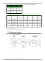
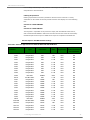
1
XBee‐PRO® XSC RF Module ‐ Product Manual XBee-PRO® XSC RF Module RF Module Operation RF Module Configuration Appendices Product Manual For RF Module Part Number: XBP09-XC ... XBP9B-XC ... 900 MHz RF Modules by Digi International Inc. XBee-PRO® XSC RF Module 90000938_E August 2,2012 © 2012 Digi International, Inc. i XBee‐PRO® XSC RF Module ‐ Product Manual © 2012 Digi International, Inc. All rights reserved No part of the contents of this manual may be transmitted or reproduced in any form or by any means without the written permission of Digi International, Inc. XBee‐PRO® is a registered trademark of Digi International Inc. Technical Support: Phone: (801) 765‐9885 Email. rf‐[email protected] © 2012 Digi International, Inc. ii XBee‐PRO® XSC RF Modules Contents 1. XBee-PRO® XSC RF Module 4 Key Features 4 Worldwide Acceptance 4 Specifications 5 Pin Signals 6 Electrical Characteristics 7 Timing Specifications 7 Mechanical Drawings 8 2. RF Module Operation 9 Serial Communications 9 UART-Interfaced Data Flow 9 Serial Data 9 Flow Control 10 Modes of Operation 11 Idle Mode 11 Transmit Mode 11 Sleep Mode 13 Command Mode 15 3. RF Module Configuration 18 XBee Programming Examples 18 AT Commands 18 Binary Commands 18 Command Reference Table 19 Command Descriptions 20 4. RF Communication Modes 37 Addressing 38 Address Recognition 38 Basic Communications 39 Streaming Mode (Default) 39 Repeater Mode 40 Acknowledged Communications 43 Acknowledged Mode 43 Agency Certifications 46 FCC (United States) Certification 46 Labeling Requirements 46 FCC Notices 46 Limited Modular Approval 47 FCC-approved Antennas 47 IC (Industry Canada) Certification 47 Additional Information 52 1-Year Warranty 52 Contact Digi 52 © 2012 Digi International, Inc. iii XBee‐PRO® XSC RF Modules 1. XBee‐PRO® XSC RF Module The XBee-PRO XSC (900 MHz) RF Modules were engineered to afford RF Modules and integrators an easy-to-use RF solution that provides reliable delivery of critical data between remote devices. These modules come configured to sustain reliable long-range wireless links. The XBee Module is a drop-in wireless solution that transfers a standard asynchronous serial data stream. The S3 hardware variant is a legacy design and will become obsolete. New and old designs should use the S3B hardware variant, which features better performance, lower current draw, and is backward compatible with and a direct replacement for S3 radios. The S3B hardware with XSC firmware is also fully backward compatible (serial interface and over-the-air) with the 9XStream radios. 1.1. Key Features Long Range Data Integrity Easy-to-Use XBee-PRO XSC-S3: • Indoor/Urban: 1200' (370m) • No configuration required for out-of-the-box RF data communications • Outdoor line-of-sight: Up to 6 miles (9.6 km) • Advanced configurations available through standard AT & binary commands • Outdoor line-of-sight: Up to 15 miles (24 km) w/ high gain antenna • Portable (small form factor easily designed into a wide range of data radio systems) • Receiver Sensitivity: -106 dBm, • Software-selectable serial interface baud rates • I/O Support: CTS, RTS (& more) XBee-PRO XSC-S3B: • Indoor/Urban range: 2000’ (610 m) • Outdoor line-of-sight range: 9 miles (14 km) • Receiver Sensitivity: -109 dBm • Support for multiple data formats (parity, start and stop bits, etc.) • Power-saving Sleep Modes Advanced Networking & Security • True peer-to-peer (no “master” required) communications • Point-to-point & point-to-multipoint topologies supported • Retries and Acknowledgements • 7 hopping channels, each with over 65,000 available network addresses • FHSS (Frequency Hopping Spread Spectrum) 1.1.1. Worldwide Acceptance FCC Certified (USA) - Refer to Appendix A for FCC Requirements. Systems that include XBee-PRO Modules inherit Digi’s FCC Certification ISM (Industrial, Scientific & Medical) frequency band Manufactured under ISO 9001:2000 registered standards XBee-PRO™ XSC (900 MHz) RF Modules are approved for use in US and Canada. RoHS compliant © 2012 Digi International, Inc. 4 XBee‐PRO® XSC RF Modules 1.2. Specifications Table 1‐01. XBee‐PRO XSC RF Module Specifications Specification XBee-PRO XSC (S3 Hardware) XBee-PRO XSC (S3B Hardware) Up to 1200ft (370m) up to 2000ft (610m) Performance Indoor/Urban Range Up to 9 miles (14km) w/ dipole antenna Up to 28 miles (45km) w/ high-gain antenna Up to 6 miles (9.6km) w/ dipole antenna Up to 15 miles (24km) w/ high-gain antenna Outdoor line-of-sight Range 125 - 65,000 bps (Software selectable, includes non-standard baud rates) Interface Data Rate Throughput Data Rate 9,600 bps RF Data Rate Transmit Power Output 9.6kbps or 19.2kbps 10kbps 10kbps or 20kbps +20dBm (100mW) Up to 24dBm (250mW) software selectable Receiver Sensitivity -106dBm -109dBm at 9600 baud -107dBm at 19200 baud Power Requirements Supply Voltage 3.0-3.6 VDC regulated 2.4 to 3.6VDC Receive Current 65mA 26mA typical Transmit Current 265mA 215mA at 24dBm 50uA 2.5uA typical @3.3v Power Down Current General Frequency Range 902-928MHz (located in the 900MHz ISM Band) Spread Spectrum Frequency Hopping Network Topology Point-to-Point, Peer-to-Peer, Point-to-Multipoint Channel Capacity 7 hop sequences share 25 frequencies Board-level Serial Data Interface (S3B) 3V CMOS UART (5V-tolerant) 3V CMOS UART Physical Properties 1.297" x 0.962" x 0.215 (3.29cm x 2.44cm x 0.546cm) Note: Dimensions do not include connector/antenna or pin lengths Module Board Size Weight Connector 5 to 8 grams, depending on the antenna option 2 rows of 10 pins, 22mm apart with 2mm spaced male Berg-type headers Operating Temperature -40 to 85º C (industrial) Antenna Options Integrated Wire ¼ wave monopole, 3.25” (8.26cm) length, 1.9dBi Gain RF Connector Reverse-polarity SMA or U.FL Impedance 50 ohms unbalanced Certifications FCC Part 15.247 MCQ-XBEEXSC MCQ-XBPS3B Industry Canada (IC) 1846A-XBEEXSC 1846A-XBPS3B Europe N/A RoHS Compliant Australia N/A © 2012 Digi International, Inc. Pending 5 XBee‐PRO® XSC RF Modules 1.3. Pin Signals Figure 1‐01. XBee‐PRO XSC RF Module Pin Numbers (top view, shield underneath) Table 1‐02. J1 Pin Signal Descriptions (Low‐asserted signals distinguished with a horizontal line over signal name.) Module Pin Public Signal 1 VCC Notes When Active Function I Supply Voltage I/O 2 DO (Data Out) O n/a Serial data exiting the module (to the UART host). Refer to the Serial Communications section for more information 3 DI (Data In I n/a Serial data entering the module (from UART host). Refer to the Serial Communications section for more information. 4 DO3 / RX LED O high Pin is driven high during RF data reception; otherwise, the pin is driven low. Refer to the CD Command section to enable. 5 Reset **Has a pull up I/O resistor low Re-boot module.(minimum pulse is 90us) Open Drain configuration. Module will drive reset line low momentarily on reboot and power up. 6 Config *Has a pull up resistor I low / high Pin can be used as a backup method for entering Command Mode during power-up. Primary method is with “+++”. Refer to the AT Commands section for more information. 7 O Driven high 8 NC 9 DI3 / SLEEP 10 GND *Has a pull up resistor I Do not Connect Do not Connect high By default, DI3 pin is not used. To configure this pin to support Sleep Modes, refer to the Sleep Mode, SM Command and PW Command sections. Ground 11 O Driven high Do not Connect 12 DO2 / CTS / RS-485 Enable O low CTS (clear-to-send) flow control - When pin is driven low, UART host is permitted to send serial data to the module. Refer to the Serial Communications and CS Command sections for more information. ---------------------------------------------------------------RS-485 Enable - To configure this pin to enable RS-485 (2-wire or 4-wire) communications, refer to the Serial Communications and CS Command sections. 13 ON / Sleep O high high = Indicates power is on and module is not in Sleep Mode. Low = Sleep mode or module is unpowered 14 VREF I n/a Not used on this module. For compatibility with other XBee modules, we recommend connecting this pin to a voltage reference if Analog sampling is desired. Otherwise, connect to GND. n/a low = TX - Pin pulses low during transmission -------------------------------------------------------------high = PWR - Indicates power is on and module is not in Sleep Mode I low RTS (request-to-send) flow control - By default, this pin is not used. To configure this pin to regulate the flow of serial data exiting the module, refer to the Serial Communications and RT Command sections. --------------------------------------------------------------CMD -Refer to Binary Commands and RT Command sections to enable binary command programming. 17 O Driven low Do not Connect 18 O Driven low Do not Connect 19 O Driven low Do not Connect 20 O Driven low Do not Connect 15 16 TX / PWR DI2 / RTS / CMD O *Has a pull down resistor Note:*S3 has a 100k pull‐up. S3B has internal pull‐up. **S3 has 10k pull‐up. S3B has internal pull‐up. © 2012 Digi International, Inc. 6 XBee‐PRO® XSC RF Modules 1.4. Electrical Characteristics Figure 1‐02. System Block Diagram Basic wireless link between hosts The data flow sequence is initiated when the first byte of data is received in the DI Buffer of the transmitting module (XBee Module A). As long as XBee Module A is not already receiving RF data, data in the DI Buffer is packetized, then transmitted over-the-air to XBee Module B. 1.4.1. Timing Specifications Figure 1‐03. Timing Specifications (“A” and “B” refer to Figure 1‐02.) Host A sends serial data to XBee Module A D IN A T ST RFOUT A After TST , contents of D IN Buffer are assembled into packet and transmitted A Transmits over air B Receives T TX TX/PWR LED on XBee Module A pulses off briefly to indicate RF transmission TX LED A T TL If 16-bit CRC checks out, data is shifted out serial port to Host B D OUT B TCLDL (Optional) Set ATCS = 1 to use CTS as RS-485 TX enable low-asserted signal CTS B TCHDH RX LED B RX LED pulses on briefly to indicate RF reception T RL © 2012 Digi International, Inc. 7 XBee‐PRO® XSC RF Modules Table 1‐03. Typical AC Characteristics (SY parameter = 0, symbols correspond to Figure 1‐02 and Figure 1‐03.) Symbol Description 9600 baud rate (32 byte packet) TTX Latency from the time data is transmitted until received 72.0 ms TTL Time that TX/PWR pin is driven low 16.8 ms TRL Time that RX LED pin is driven high 25.6 ms TST Channel Initialization Time 35.0 ms Table 1‐04. DC Characteristics (Vcc = 3.0‐3.6 VDC) Symbol Parameter Vcc Module Supply Voltage VIL Input Low Voltage VIH Condition Min Max Units *3.0 Typical 3.6 V All input signals -0.3 0.3Vcc V Input High voltage All input signals 0.7Vcc Vcc + 0.3 ** V VOL Output Low-Level Voltage Iout = Iout_Max 0.4 V VOH Output High-Level Voltage Iout = Iout_Max IL Input Leakage Current ***With Pull-up resistors disabled IO1 Output Current IO2 Output Current Vcc-0.4 V 40 400 nA pins 2, 15 (Dout, ~TX/ Pwr) 2 mA pins 4, 12, 13 (DCD,~CTS,ON/~Sleep) 8 mA Note: *Min Voltage for S3B is 2.4v, however Max Power will be reduced and Sensitivity may degrade. **S3 is tolerant up to 5.5v on input pins. ***S3B can have pull‐ups enabled and still maintain low leakage current. 1.5. Mechanical Drawings Figure 1‐04. Mechanical Drawings © 2012 Digi International, Inc. 8 XBee‐PRO® XSC RF Modules 2. RF Module Operation 2.1. Serial Communications The XBee module interfaces to a host device through a CMOS-level asynchronous serial port. Through its serial port, the module can communicate with any UART voltage compatible device or through a level translator to any RS-232/485/422 device. 2.1.1. UART-Interfaced Data Flow Devices that have a UART interface can connect directly through the pins of the XBee module as shown in the figure below. Figure 2‐01. System Data Flow Diagram in a UART‐interfaced environment (Low‐asserted signals distinguished with horizontal line over signal name.) DIN (data in) DIN (data in) DOUT (data out) DOUT (data out) 2.1.2. Serial Data Data enters the XBee module through the DI pin as an asynchronous serial signal. The signal should idle high when no data is being transmitted. The UART performs tasks, such as timing and parity checking, that are needed for data communications. Serial communication consists of two UARTs, one being the XBee's and the other being the Microcontroller's, configured with compatible parameters (baud rate, parity, start bits, stop bits, data bits) to have successful communication. Each data packet consists of a start bit (low), 8 data bits (least significant bit first) and a stop bit (high). The following figure illustrates the serial bit pattern of data passing through the module. Figure 2‐02. UART data packet 0x1F (decimal number “31”) as transmitted through the XBee Module Example Data Format is 8‐N‐1 (bits ‐ parity ‐ # of stop bits) © 2012 Digi International, Inc. 9 XBee‐PRO® XSC RF Modules 2.1.3. Flow Control Figure 2‐03. Internal Data Flow Diagram (The five most commonly‐used pin signals shown.) DI (Data In) Buffer and Flow Control When serial data enters the XBee module through the DI Pin, then the data is stored in the DI Buffer until it can be transmitted. When the RO parameter threshold is satisfied (refer to Transmit Mode and Command Descriptions sections for more information), the module attempts to initialize an RF connection. If the module is already receiving RF data, the serial data is stored in the module's DI Buffer. If the DI buffer becomes full, hardware or software flow control must be implemented in order to prevent overflow (loss of data between the host and XBee RF Module). How to eliminate the need for flow control: • Send messages that are smaller than the DI buffer size, which is generally around 1,000 bytes. • Interface at a lower baud rate (BD parameter) than the fixed RF data rate with the Retries functionality (RR parameter) disabled. Two cases in which the DI Buffer may become full and possibly overflow: • If the serial interface data rate is set higher than the RF data rate of the module, the module will receive data from the host faster than it can transmit the data over-the-air. • If the module is receiving a continuous stream of data, monitoring data on a network, or awaiting acknowledgments for Retries functionality, any serial data that arrives on the DI pin is placed in the DI Buffer. The data in the DI buffer will be transmitted over-the-air when the module no longer detects RF data in the network. Hardware Flow Control (CTS). When the DI buffer is 65 bytes away from being full; by default, the module de-asserts (high) CTS to signal to the host device to stop sending data [refer to FT (Flow Control Threshold) and CS (DO2 Configuration) Commands]. CTS is re-asserted after the DI Buffer has 34 bytes of memory available. Software Flow Control (XON). XON/XOFF software flow control can be enabled using the FL (Software Flow Control) command. DO (Data Out) Buffer and Flow Control When RF data is received, the data enters the DO buffer and is then sent out the serial port to a host device. Once the DO Buffer reaches capacity, any additional incoming RF data is lost. Two cases in which the DO Buffer may become full and possibly overflow: • If the RF data rate is higher than the set interface data rate of the module, the module will receive data from the transmitting module faster than it can send the data to the host. • If the host does not allow the RF module to send data out of the DO buffer because of hardware or software flow control. Hardware Flow Control (RTS). If RTS is enabled for flow control (RT Parameter = 2), data will not be sent out the DO Buffer as long as RTS (pin 16) is de-asserted. Software Flow Control (XOFF). XON/XOFF software flow control can be enabled using the FL (Software Flow Control) Command. This option only works with ASCII data. © 2012 Digi International, Inc. 10 XBee‐PRO® XSC RF Modules 2.2. Modes of Operation XBee-PRO® XSC RF Modules operate in five modes. Figure 2‐04. Modes of Operation 2.2.1. Idle Mode When not receiving or transmitting data, the RF module is in Idle Mode. The module shifts into the other modes of operation under the following conditions: • Transmit Mode (Serial data is received in the DI Buffer) • Receive Mode (Valid RF data is received through the antenna) • Sleep Mode (Sleep Mode condition is met) • Command Mode (Command Mode Sequence is issued) 2.2.2. Transmit Mode When the first byte of serial data is received from the UART in the DI buffer, the modem attempts to shift to Transmit Mode and initiate an RF connection with other modems. After transmission is complete, the modem returns to Idle Mode. RF transmission begins after either of the following criteria is met: 1. RB bytes have been received in the DI buffer and are pending for RF transmission [refer to RB (Packetization Threshold) command, p34]. - The RB parameter may be set to any value between 1 and the RF packet size (PK), inclusive. When RB = 0, the packetization threshold is ignored. 2. At least one character has been received in the DI buffer (pending for RF transmission) and RO time has been observed on the UART [refer to RO (Packetization Timeout) command]. - The time out can be disabled by setting RO to zero. In this case, transmission will begin after RB bytes have been received in the DI buffer. Note: RF reception must complete before the modem is able to enter into Transmit Mode. After either RB or RO conditions are met, the modem then initializes a communications channel. [Channel initialization is the process of sending an RF initializer that synchronizes receiving modems with the transmitting modem. During channel initialization, incoming serial data accumulates in the DI buffer.] Serial data in the DI buffer is grouped into RF packets [refer to PK (RF Packet Size)]; converted to RF data; then transmitted over-the-air until the DI buffer is empty. RF data, which includes the payload data, follows the RF initializer. The payload includes up to the maximum packet size (PK Command) bytes. As the transmitting modem nears the end of the transmission, it inspects the DI buffer to see if more data exists to be transmitted. This could be the case if more than PK bytes were originally pending in the DI buffer or if more bytes arrived from the UART after the transmission began. If more data is pending, the transmitting modem assembles a subsequent packet for transmission. © 2012 Digi International, Inc. 11 XBee‐PRO® XSC RF Modules RF Packet The RF packet is the sequence of data used for communicating information between Digi Radios. An RF Packet consists of an RF Initializer and RF Data. When streaming multiple RF packets, the RF Initializer is only sent in front of the first packet. RF Initializer An RF initializer is sent each time a new connection sequence begins. The RF initializer contains channel information that notifies receiving modems of information such as the hopping pattern used by the transmitting modem. The first transmission always sends an RF initializer. An RF initializer can be of various lengths depending on the amount of time determined to be required to prepare a receiving modem. For example, a wake-up initializer is a type of RF initializer used to wake remote modems from Sleep Mode (Refer to the FH, LH, HT and SM Commands for more information). The length of the wake-up initializer should be longer than the length of time remote modems are in cyclic sleep. © 2012 Digi International, Inc. 12 XBee‐PRO® XSC RF Modules Header The header contains network addressing information that filters incoming RF data. The receiving modem checks for a matching Hopping Channel (HP parameter), Vendor Identification Number (ID parameter) and Destination Address (DT parameter). Data that does not pass through all three network filter layers is discarded. CRC (Cyclic Redundancy Check) To verify data integrity and provide built-in error checking, a 16-bit CRC (Cyclic Redundancy Check) is computed for the transmitted data and attached to the end of each RF packet. On the receiving end, the receiving modem computes the CRC on all incoming RF data. Received data that has an invalid CRC is discarded. Receive Mode If a module detects RF data while operating in Idle Mode, the module transitions into Receive Mode to start receiving RF packets. Figure 2‐05. Reception of RF Data After a packet is received, the module checks the CRC (cyclic redundancy check) to ensure that the data was transmitted without error. If the CRC data bits on the incoming packet are invalid, the packet is discarded. If the CRC is valid, the packet proceeds to the DO Buffer. The module returns to Idle Mode after valid RF data is no longer detected or after an error is detected in the received RF data. If serial data is stored in the DI buffer while the module is in Receive Mode, the serial data will be transmitted after the module is finished receiving data and returns to Idle Mode. 2.2.3. Sleep Mode Sleep Modes enable the XBee module to operate at minimal power consumption when not in use. The following Sleep Mode options are available: • Pin Sleep • Cyclic Sleep For the module to transition into Sleep Mode, the module must have a non-zero SM (Sleep Mode) Parameter and one of the following must occur: • The module is idle (no data transmission or reception) for a user-defined period of time [Refer to the ST (Time before Sleep) Command]. • SLEEP is asserted (only for Pin Sleep option). In Sleep Mode, the module will not transmit or receive data until the module first transitions to Idle Mode. All Sleep Modes are enabled and disabled using SM Command. Transitions into and out of Sleep Modes are triggered by various events as shown in the table below. © 2012 Digi International, Inc. 13 XBee‐PRO® XSC RF Modules Table 2‐01. Sleep Mode Setting Pin Sleep (SM = 1) Cyclic Sleep (SM = 3-8) Summary of Sleep Mode Configurations Transition into Sleep Mode Microcontroller can shut down and wake modules by asserting (high) SLEEP (pin 9). Note: The module will complete a transmission or reception before activating Pin Sleep. Automatic transition to Sleep Mode occurs in cycles as defined by the SM (Sleep Mode) Command. Transition out of Sleep Mode Related Commands Typical Power Consumption (S3) Typical Power Consumption (S3B) De-assert (low) SLEEP (pin 9). SM 50 µA 2.5uA 76 µA when sleeping 2.5uA when sleeping After the cyclic sleep time interval elapses. Note: Module can be SM, ST, HT, Note: The cyclic sleep time interval must be forced into Idle Mode LH, PW shorter than the “Wake-up Initializer Timer” if PW (Pin Wake-up) Command is enabled. (set by LH Command). Pin Sleep (SM = 1) In order to achieve this state, SLEEP pin must be asserted (high). The module remains in Pin Sleep until the SLEEP pin is de-asserted. After enabling Pin Sleep, the SLEEP pin controls whether the XBee module is active or in Sleep Mode. When SLEEP is de-asserted (low), the module is fully operational. When SLEEP is asserted (high), the module transitions to Sleep Mode and remains in its lowest power-consuming state until the SLEEP pin is de-asserted. SLEEP is only active if the module is setup to operate in this mode; otherwise the pin is ignored. Once in Pin Sleep Mode, CTS is de-asserted (high), indicating that data should not be sent to the module. The PWR pin is also de-asserted (low) when the module is in Pin Sleep Mode. Note: The module will complete a transmission or reception before activating Pin Sleep. Cyclic Sleep (SM = 3-8) Cyclic Sleep is the Sleep Mode in which the XBee module enters into a low-power state and awakens periodically to determine if any transmissions are being sent. When Cyclic Sleep settings are enabled, the XBee module goes into Sleep Mode after a userdefined period of inactivity (no transmission or reception on the RF channel). The user-defined period is determined by ST (Time before Sleep) Command. While the module is in Cyclic Sleep Mode, CTS is de-asserted (high) to indicate that data should not be sent to the module during this time. When the module awakens to listen for data, CTS is asserted and any data received on the DI Pin is transmitted. The PWR pin is also de-asserted (low) when the module is in Cyclic Sleep Mode. The module remains in Sleep Mode for a user-defined period of time ranging from 0.5 seconds to 16 seconds (SM Parameters 3 through 8). After this interval of time, the module returns to Idle Mode and listens for a valid data packet for 100 ms. If the module does not detect valid data (on any frequency), the module returns to Sleep Mode. If valid data is detected, the module transitions into Receive Mode and receives incoming RF packets. The module then returns to Sleep Mode after a Period of inactivity that is determined by ST “Time before Sleep” Command. The module can also be configured to wake from cyclic sleep when SLEEP (pin 9) is de-asserted (low). To configure a module to operate in this manner, PW (Pin Wake-up) Command must be issued. Once SLEEP is de-asserted, the module is forced into Idle Mode and can begin transmitting or receiving data. It remains active until no data is detected for the period of time specified by the ST Command, at which point it resumes its low-power cyclic state. Note: The cyclic interval time defined by SM (Sleep Mode) Command must be shorter than the interval time defined by LH (Wake-up Initializer Timer). For example: If SM=4 (Cyclic 1.0 second sleep), the LH Parameter should equal 0x0B ("1.1" seconds). With these parameters set, there is no risk of the receiving module being asleep for the duration of wake-up initializer transmission. “Cyclic Scanning” explains in further detail the relationship between “Cyclic Sleep” and “Wake-up Initializer Timer” © 2012 Digi International, Inc. 14 XBee‐PRO® XSC RF Modules Cyclic Scanning. Each RF transmission consists of an RF Initializer and payload. The wake-up initializer contains initialization information and all receiving modules must wake during the wakeup initializer portion of data transmission in order to be synchronized with the transmitting module and receive the data. Figure 2‐06. Correct Configuration (LH > SM) Length of the wake‐up initializer exceeds the time interval of Cyclic Sleep. The receiver is guaranteed to detect the wake‐up initializer and receive the accompanying payload data. Figure 2‐07. Incorrect Configuration (LH < SM) Length of wake‐up initializer is shorter than the time interval of Cyclic Sleep. This configuration is vulnerable to the receiver waking and missing the wake‐up initializer (and therefore also the accompanying payload data). 2.2.4. Command Mode To modify or read module parameters, the module must first enter into Command Mode, the state in which received characters on the UART are interpreted as commands. Two command types are available for programming the module: • AT Commands • Binary Commands For modified parameter values to persist in the module registry, changes must be saved to non-volatile memory using WR (Write) Command. Otherwise, parameters are restored to previously saved values after the module is powered off and then on again. AT Commands To Enter AT Command Mode: • Send the 3-character command sequence “+++” and observe guard times before and after the command characters. [refer to ‘Default AT Command Mode Sequence’ below.] The ‘Terminal’ tab (or other serial communications software) of the X-CTU Software can be used to enter the sequence. [OR] • Assert (low) the CONFIG pin and either turn the power going to the module off and back on. (If using a Digi XBIB-R Interface Board, the same result can be achieved by holding the DataIn line low (also known as a break) while rebooting the module by pressing the reset button on the module assembly [module assembly = module mounted to an interface board]). © 2012 Digi International, Inc. 15 XBee‐PRO® XSC RF Modules Default AT Command Mode Sequence (for transition to Command Mode): • No characters sent for one second [refer to the BT (Guard Time Before) Command] • Input three plus characters (“+++”) within one second [refer to the CC (Command Sequence Character) Command.] • No characters sent for one second [refer to the AT (Guard Time After) Command.] To Send AT Commands: Send AT commands and parameters using the syntax shown below. Figure 2‐8. Syntax for sending AT Commands To read a parameter value stored in the module register, leave the parameter field blank. The preceding example would change the module’s Destination Address to “0x1F”. To store the new value to non-volatile (long term) memory, the Write (ATWR) command must subsequently be sent before powering off the module. System Response. When a command is sent to the module, the module will parse and execute the command. Upon successful execution of a command, the module returns an “OK” message. If execution of a command results in an error, the module returns an “ERROR” message. To Exit AT Command Mode: • If no valid AT Commands are received within the time specified by CT (Command Mode Timeout) Command, the module automatically returns to Idle Mode. [OR] • Send ATCN (Exit Command Mode) Command. For an example of programming the RF module using AT Commands and descriptions of each configurable parameter, refer to the “RF Module Configuration” chapter. Binary Commands Sending and receiving parameter values using binary commands is the fastest way to change operating parameters of the module. Binary commands are used most often to sample signal strength (RS parameter) and/or error counts; or to change module addresses and channels for polling systems when a quick response is necessary. Since the sending and receiving of parameter values takes place through the same data path as 'live' data (received RF payload), follow the CTS pin as outlined in Figure 2-012 to distinguish between the two types of data (commands vs 'live' data). Common questions regarding the use of binary commands: • What are the implications of asserting CMD while live data is being sent or received? • After sending serial data, is there a minimum time delay before CMD can be asserted? • Is a time delay required after CMD is de-asserted before payload data can be sent? • How to discern between live data and data received in response to a command? CMD (pin 16) must be asserted in order to send binary commands to the module. The CMD pin can be asserted to recognize binary commands anytime during the transmission or reception of data. The status of the CMD signal is only checked at the end of the stop bit as the byte is shifted into the serial port. The application does not allow control over when data is received, except by waiting for dead time between bursts of communication. If the command is sent in the middle of a stream of payload data to be transmitted, the command will essentially be executed in the order it is received. If the radio is continuously receiving data, the radio will wait for a break in the received data before executing the command. The CTS signal will frame the response coming from the binary command request [Figure 2-09]. © 2012 Digi International, Inc. 16 XBee‐PRO® XSC RF Modules A minimum time delay of 100 µs (after the stop bit of the command byte has been sent) must be observed before pin 5 can be de-asserted. The command executes after all parameters associated with the command have been sent. If all parameters are not received within 0.5 seconds, the module aborts the command and returns to Idle Mode. Note: Binary commands that return only one parameter byte must also be written with two parameter bytes, 0-padded, LSB first. Refer to “Programming Examples” section [p18] for a binary programming example. Commands can be queried for their current value by sending the command logically ORed (bitwise) with the value 0x80 (hexadecimal) with CMD asserted. When the binary value is sent (with no parameters), the current value of the command parameter is sent back through the DO pin. Figure 2‐09. Binary Command Write then Read Signal #4 is CMD (pin 16) Signal #1 is the DIN (pin 3) signal to the radio Signal #2 is the DOUT (pin 2) signal from the radio Signal #3 is CTS (pin 12) In this graph, a value was written to a register and then read out to verify it. While not in the middle of other received data, note that the CTS signal outlines the data response out of the module. IMPORTANT: For the XBee module to recognize a binary command, the RT (DI2 Configuration) parameter must be set to one. If binary programming is not enabled RT = 0 or 2, the module will not recognize that the CMD pin is asserted and therefore will not recognize the data as binary commands. © 2012 Digi International, Inc. 17 XBee‐PRO® XSC RF Modules 3. RF Module Configuration 3.1. XBee Programming Examples For information about entering and exiting AT and Binary Command Modes, refer to the Command Mode section. 3.1.1. AT Commands To Send AT Commands (Using the ‘Terminal’ tab of the X-CTU Software) Example: Utilize the 'Terminal' tab of the X-CTU Software to change the module's DT (Destination Address) parameter and save the new address to non-volatile memory. This example requires the installation of Digi’s X-CTU Software and a serial connection to a PC. Note: Do not send com‐ mands to the module during flash program‐ ming (when parameters are being written to the module registry). Wait for the “OK” sys‐ tem response that fol‐ lows the ATWR command before enter‐ ing the next command or use flow control. Select the ‘Terminal’ tab of the X-CTU Software and enter the following command lines: Method 1 (One line per command) Send AT Command +++ ATDT <Enter> ATDT1A0D <Enter> ATWR <Enter> ATCN <Enter> System Response OK <CR> (Enter into Command Mode) {current value} <CR> (Read Destination Address) OK <CR> (Modify Destination Address) OK <CR> (Write to non-volatile memory) OK <CR> (Exit Command Mode) Method 2 (Multiple commands on one line) Send AT Command +++ ATDT <Enter> ATDT1A0D,WR,CN <Enter> System Response OK <CR> (Enter into Command Mode) {current value} <CR> (Read Destination Address) OK <CR> (Execute commands) Note: When using X-CTU Software to program a module, PC com port settings must match the baud (interface data rate), parity & stop bits parameter settings of the module. Use the 'Com Port Setup' section of the “PC Settings” tab to configure PC com port settings to match those of the module. 3.1.2. Binary Commands To Send Binary Commands Example: Use binary commands to change the XBee module's destination address to 0x1A0D and save the new address to non-volatile memory. 1. RT Command must be set to “1” in AT Command Mode to enable binary programming. 2. Assert CMD (Pin 16 is driven high). (Enter Binary Command Mode) 3. Send Bytes (parameter bytes must be 2 bytes long): (Send DT (Destination Address) Command) 00 (Least significant byte of parameter bytes 0D (Most significant byte of parameter bytes) 1A (Send WR (Write) Command) 08 De-assert CMD (Pin 16 is driven (Exit Binary Command Mode) 4. low) Note: CTS is de-asserted high when commands are being executed. Hardware flow control must be disabled as CTS will hold off parameter bytes. © 2012 Digi International, Inc. 18 XBee‐PRO® XSC RF Modules 3.2. Command Reference Table Table 3‐01. AT Commands (The RF Module expects numerical values in hexadecimal. “d” denotes decimal equivalent.) AT Command Binary Command *AM AT Command Category # Bytes Returned Factory Default AT Command Name Range 0x3A (58d) Auto-set MY - Networking & Security - - 0x05 (5d) Guard Time After 0x02 – 0xFFFF [x 100 msec] Command Mode Options 2 0x0A (10d) Interface Data Rate Standard baud rates: 0–6 Non-standard baud rates: 0x7D – 0xFFFF Serial Interfacing 2 0x03 9600bps BD 0x15 (21d) BT 0x04 (4d) Guard Time Before 2 – 0xFFFF [x 100 msec] Command Mode Options 2 0x0A (10d) CC 0x13 (19d) Command Sequence Character 0x20 – 0x7F Command Mode Options 1 0x2B (“+”) CD 0x28 (40d) DO3 Configuration 0-4 Serial Interfacing 1 0 CN 0x09 (9d) Exit AT Command Mode - Command Mode Options - - CS 0x1F (31d) DO2 Configuration 0–4 Serial Interfacing 1 0 CT 0x06 (6d) Command Mode Timeout 0x02 – 0xFFFF [x 100 msec] Command Mode Options 2 0xC8 (200d) DT 0x00 (0d) Destination Address 0 – 0xFFFF Networking 2 0 E0 0x0A (10d) Echo Off - Command Mode Options - - E1 0x0B (11d) Echo On - Command Mode Options - - ER 0x0F (15d) Receive Error Count 0 – 0xFFFF Diagnostics 2 0 FH 0x0D (13d) Force Wake-up Initializer - Sleep (Low Power) - - FL 0x07 (7d) Software Flow Control 0–1 Serial Interfacing 1 0 FR FT N/A Forces the module to Reset (Special) 0x24 (36d) Flow Control Threshold 0 – (DI buffer – 0x11) [bytes] Serial Interfacing 2 varies GD 0x10 (16d) Receive Good Count 0 – 0xFFFF Diagnostics 2 0 HP 0x11 (17d) Hopping Channel 0–6 Networking 1 0 HT 0x03 (3d) Time before Wake-up Initializer 0 – 0xFFFF [x 100 msec] Sleep (Low Power) 2 0xFFFF User set table: 0x10 - 0x7FFF Read-only: 0x8000 – 0xFFFF Networking 2 - ID 0x27 (39d) Module VID LH 0x0C (12d) Wake-up Initializer Timer 0 – 0xFF [x 100 msec] Sleep (Low Power) 1 1 MD 0x32 (50d) RF Mode 0–4 Networking & Security 1 0 0xFFFF MK 0x12 (18d) Address Mask 0 – 0xFFFF Networking 2 *MY 0x2A (42d) Source Address 0 – 0xFFFF Networking & Security 2 0xFFFF NB 0x23 (35d) Parity 0–5 Serial Interfacing 1 0 PC 0x1E (30d) Power-up Mode 0–1 Command Mode Options 1 0 *PK 0x29 (41d) RF Packet Size 0 - 0x100 [bytes] Serial Interfacing 2 0x40 (64d) *PL 0x3c (60d) RF Power Level 0-4 (Special) 1 4 PW 0x1D (29d) Pin Wake-up 0–1 Sleep (Low Power) 1 0 *RB 0x20 (32d) Packetization Threshold 0 - 0x100 [bytes] Serial Interfacing 2 0x01 RE 0x0E (14d) Restore Defaults - (Special) - - RN 0x19 (25d) Delay Slots 0 – 0xFF [slots] Networking 1 0 RO 0x21 (33d) Packetization Timeout 0 – 0xFFFF [x 200 µsec] Serial Interfacing 2 0 RP 0x22 (34d) RSSI PWM Timer 0 - 0x7F [x 100 msec] Diagnostics 1 0 RR 0x18 (24d) Retries 0 – 0xFF Networking 1 0 RS 0x1C (28d) RSSI 0x06 – 0x36 [read-only] Diagnostics 1 - RT 0x16 (22d) DI2 Configuration 0-2 Serial Interfacing 1 0 *RZ 0x2C (44d) DI Buffer Size [read-only] Diagnostics - - SB 0x36 (54d) Stop Bits 0-1 Serial Interfacing 1 0 SH 0x25 (37d) Serial Number High 0 – 0xFFFF [read-only] Diagnostics 2 - SL 0x26 (38d) Serial Number Low 0 – 0xFFFF [read-only] Diagnostics 2 - SM 0x01 (1d) Sleep Mode 0, 1, 3 - 8 Sleep (Low Power) 1 0 ST 0x02 (2d) Time before Sleep 0x10 – 0xFFFF [x 100 msec] Sleep (Low Power) 2 0x64 (100d) SY 0x17 (23d) Time before Initialization 0 – 0xFF [x 100 msec] Networking 1 0 (disabled) TR 0x1B (27d) Transmit Error Count 0 – 0xFFFF Diagnostics 2 0 © 2012 Digi International, Inc. 19 XBee‐PRO® XSC RF Modules TT 0x1A (26d) Streaming Limit 0 – 0xFFFF [0 = disabled] Networking 2 VR 0x14 (20d) Firmware Version 0 - 0xFFFF [read-only] Diagnostics 2 0xFFFF - WR 0x08 (8d) Write - (Special) - - NOTE: AT Commands issued without a parameter value are interpreted as queries and will return the currently stored parameter. *Commands only supported on S3B hardware. 3.3. Command Descriptions Commands in this section are listed alphabetically. Command categories are designated between the “< >” symbols that follow each command title. Modules expect numerical values in hexadecimal and those values are designated by a “0x” prefix. Modules operating within the same network should contain the same firmware platform to ensure the same AT Command parameters are supported. AM (Auto-set MY) Command Command Summary AT Command: ATAM Binary Command: 0x3A (58 decimal) This command is only supported on S3B modules. Description <Networking & Security> AM Command is used to automatically set the MY (Source Address) parameter from the factory-set module serial number. The address is formed with bits 29, 28 and 13-0 of the serial number (in that order). AT (Guard Time After) Command Command Summary AT Command: ATAT Binary Command: 0x05 (5 decimal) Parameter Range:0x02 – 0xFFFF [x 100 milliseconds] Number of bytes returned: 2 Default Parameter Value: 0x0A (10 decimal) Related Commands: BT (Guard Time Before), CC (Command Sequence Character) Description <Command Mode Options> AT Command is used to set the time-ofsilence that follows the command sequence character (CC Command). By default, AT Command Mode will activate after one second of silence. Refer to the AT Commands section to view the default AT Command Mode Sequence. © 2012 Digi International, Inc. 20 XBee‐PRO® XSC RF Modules BD (Interface Data Rate) Command Command Summary AT Command: ATBD Binary Command: 0x15 (21 decimal) Parameter Range (Standard baud rates): 0 –6 (Non-standard baud rates): 0x7D – 0xFFFF (125d – 65535d) Parameter Value 0 1 2 3 4 5 6 BAUD (bps) Configuration 1200 2400 4800 9600 19200 38400 57600 Number of bytes returned: 2 Default Parameter Value: Set to equal module’s factory-set RF data rate. Table 3‐02. Description <Serial Interfacing> BD Command allows the user to adjust the UART interface data rate and thus modify the rate at which serial data is sent to the module. The new baud rate does not take effect until the CN (Exit AT Command Mode) Command is issued. The RF data rate is not affected by the BD Command. Although most applications will only require one of the seven standard baud rates, non-standard baud rates are also supported. Note: If the serial data rate is set to exceed the fixed RF data rate of the module, flow control may need to be implemented as described in the Pin Signals and Flow Control sections of this manual. Non-standard Interface Data Rates: When parameter values outside the range of standard baud rates are sent, the closest interface data rate represented by the number is stored in the BD register. For example, a rate of 19200 bps can be set by sending the following command line “ATBD4B00”. NOTE: When using X-CTU Software, non-standard interface data rates can only be set and read using the X-CTU ‘Terminal’ tab. Nonstandard rates are not accessible through the ‘Modem Configuration’ tab. When the BD command is sent with a non-standard interface data rate, the UART will adjust to accommodate the requested interface rate. In most cases, the clock resolution will cause the stored BD parameter to vary from the parameter that was sent (refer to the table below). Reading the BD command (send “ATBD” command without an associated parameter value) will return the value that was actually stored to the BD register. Parameter Sent vs. Parameter Stored BD Parameter Sent (HEX) Interface Data Rate (bps) S3 BD Parameter Stored (HEX) 0 4 6 12C E100 1200 19,200 57600 300 57600 0 4 6 12B E883 S3B BD Parameter Stored (HEX) 0 4 5 12B E10D BT (Guard Time Before) Command Command Summary AT Command: ATBT Binary Command: 0x04 (4 decimal) Parameter Range:2 – 0xFFFF [x 100 milliseconds] Default Parameter Value: 0x0A (10 decimal) Number of bytes returned: 2 Related Commands: AT (Guard Time After), CC (Command Sequence Character) Description <Command Mode Options> BT Command is used to set the DI pin silence time that must precede the command sequence character (CC Command) of the AT Command Mode Sequence. Refer to the AT Commands section to view the default AT Command Mode Sequence. © 2012 Digi International, Inc. 21 XBee‐PRO® XSC RF Modules CC (Command Sequence Character) Command Command Summary AT Command: ATCC Binary Command: 0x13 (19 decimal) Parameter Range: 0x20 – 0x7F Default Parameter Value: 0x2B (ASCII “+” sign) Number of bytes returned: 1 Related Commands: AT (Guard Time After), BT (Guard Time Before) Description <Command Mode Options> CC Command is used to set the ASCII character to be used between Guard Times of the AT Command Mode Sequence (BT+ CC + AT). The AT Command Mode Sequence activates AT Command Mode (from Idle Mode). Refer to the AT Commands section [p. 18] to view the default AT Command Mode Sequence. CD (DO3 Configuration) Command AT Command: ATCD Binary Command: 0x28 (40 decimal) Parameter Range: 0 – 3 Parameter Value 0 1 2 3 4 Configuration RX LED Default high Default low (reserved) Assert only when packet addressed to module is sent Description <Command Mode Options> CD Command is used to define the behavior of the DO3/RX LED line. Default Parameter Value: 0 Number of bytes returned: 1 CN (Exit AT Command Mode) Command Command Summary AT Command: ATCN Binary Command: 0x09 (9 decimal) Description <Command Mode Options> CN Command is used to explicitly exit AT Command Mode. CS (DO2 Configuration) Command Command Summary AT Command: ATCS Binary Command: 0x1F (31 decimal) Parameter Range:0 – 4 Parameter Value 0 1 2 3 4 Configuration RS-232 flow control RS-485 TX enable low high RS-485 TX enable high low Default Parameter Value: 0 Number of bytes returned: 1 Minimum Firmware Version Required: 4.27D Description <Serial Interfacing> CS Command is used to select the behavior of the DO2 pin signal. This output can provide RS-232 flow control, control the TX enable signal (for RS485 or RS-422 operations), or set the default level for the I/O line passing function. By default, DO2 provides RS-232 CTS (Clear-to-Send) flow control. © 2012 Digi International, Inc. 22 XBee‐PRO® XSC RF Modules CT (Command Mode Time out) Command Command Summary AT Command: ATCT Binary Command: 0x06 (6 decimal) Parameter Range:0x02 – 0xFFFF [x 100 milliseconds] Default Parameter Value: 0xC8 (200 decimal, 20 seconds) Number of bytes returned: 2 Description <Command Mode Options> CT Command sets the amount of time before AT Command Mode terminates automatically. After a CT time of inactivity, the module exits AT Command Mode and returns to Idle Mode. AT Command Mode can also be exited manually using CN (Exit AT Command Mode) Command. DT (Destination Address) Command Command Summary AT Command: ATDT Binary Command: 0x00 Parameter Range:0 – 0xFFFF Default Parameter Value: 0 Number of bytes returned: 2 Related Commands: HP (Hopping Channel), ID (Module VID), MK (Address Mask) Description <Networking> DT Command is used to set the networking address of a Module. Modules use three network layers – Vendor Identification Number (ATID), Channels (ATHP), and Destination Addresses (ATDT). DT Command assigns an address to a module that enables it to communicate only with other modules having the same addresses. All modules that share the same Destination Address can communicate freely with each other. Modules in the same network with a different Destination Address (than that of the transmitter) will listen to all transmissions to stay synchronized, but will not send any of the data out their serial ports. E0 (Echo Off) Command Command Summary AT Command: ATE0 Binary Command: 0x0A (10 decimal) Description <Command Mode Options> E0 Command turns off character echo in AT Command Mode. By default, echo is off. E1 (Echo On) Command Command Summary AT Command: ATE1 Binary Command: 0x0B (11 decimal) Description <Command Mode Options> E1 Command turns on the echo in AT Command Mode. Each typed character will be echoed back to the terminal when ATE1 is active. E0 is the default. © 2012 Digi International, Inc. 23 XBee‐PRO® XSC RF Modules ER (Receive Error Count) Command Command Summary AT Command: ATER Binary Command: 0x0F (15 decimal) Parameter Range:0 – 0xFFFF Default Parameter Value: 0 Number of bytes returned: 2 Related Commands: GD (Receive Good Count) Description <Diagnostics> Set/Read the receiveerror. The error-count records the number of packets partially received then aborted on a reception error. This value returns to 0 after a reset and is not non-volatile (Value does not persist in the module’s memory after a power-up sequence). Once the “Receive Error Count” reaches its maximum value (up to 0xFFFF), it remains at its maximum count value until the maximum count value is explicitly changed or the module is reset. FH (Force Wake-up Initializer) Command Command Summary AT Command: ATFH Binary Command: 0x0D (13 decimal) Description <Sleep (Low Power)> FH Command is used to force a Wake-up Initializer to be sent on the next transmit. WR (Write) Command does not need to be issued with FH Command. Use only with cyclic sleep modes active on remote modules. FL (Software Flow Control) Command Command Summary AT Command: ATFL Binary Command: 0x07 (7 decimal) Parameter Range: 0 – 1 Parameter Value 0 1 Configuration Disable software flow control Enable software flow control Default Parameter Value: 0 Number of bytes returned: 1 Description <Serial Interfacing> FL Command is used to configure software flow control. Hardware flow control is implemented with the Module as the DO2 pin (), which regulates when serial data can be transferred to the module. FL Command can be used to allow software flow control to also be enabled. XON character used is 0x11 (17 decimal). XOFF character used is 0x13 (19 decimal). FR (Force Reset) Command Command Summary AT Command: ATFR Binary Command: Not available Description <Special> FR command is used in order to reset the module through the UART. The characters “OK”<CR> will be returned and the module will reset 100ms © 2012 Digi International, Inc. 24 XBee‐PRO® XSC RF Modules FT (Flow Control Threshold) Command Command Summary AT Command: ATFT Binary Command: 0x24 (36 decimal) Parameter Range:0 – (DI buffer size minus 0x11 bytes) Default Parameter Value: DI Buffer size minus 0x11 (17 decimal) Number of bytes returned: 2 Minimum Firmware Version Required: 4.27B Description <Serial Interfacing> Flow Control Threshold - Set or read flow control threshold. De-assert CTS and/or send XOFF when FT bytes are in the UART receive buffer. Re-assert CTS when less than FT - 16 bytes are in the UART receive buffer. GD (Receive Good Count) Command Command Summary AT Command: ATGD Binary Command: 0x10 (16 decimal) Parameter Range:0 – 0xFFFF Default Parameter Value: 0 Number of bytes returned: 2 Related Commands: ER (Receive Error Count) Description <Diagnostics> Set/Read the count of good received RF packets. Parameter value is reset to 0 after every reset and is not non-volatile (Value does not persist in the module’s memory after a power-up sequence). Once the “Receive Good Count” reaches its maximum value (up to 0xFFFF), it remains at its maximum count value until the maximum count value is manually changed or the module is reset. HP (Hopping Channel) Command Command Summary AT Command: ATHP Binary Command: 0x11 (17 decimal) Parameter Range:0 – 6 Default Parameter Value: 0 Number of bytes returned: 1 Related Commands: DT (Destination Address), ID (Module VID), MK (Address Mask) Description <Networking> HP Command is used to set the module’s hopping channel number. A channel is one of three layers of addressing available to the module. In order for modules to communicate with each other, the modules must have the same channel number since each network uses a different hopping sequence. Different channels can be used to prevent modules in one network from listening to transmissions of another. © 2012 Digi International, Inc. 25 XBee‐PRO® XSC RF Modules HT (Time before Wake-up Initializer) Command Command Summary AT Command: ATHT Binary Command: 0x03 (3 decimal) Parameter Range:0 – 0xFFFF [x 100 milliseconds] Default Parameter Value: 0xFFFF (means that long wake-up initializer will not be sent) Number of bytes returned: 2 Related Commands: LH (Wake-up Initializer Timer), SM (Sleep Mode), ST (Time before Sleep) Description <Sleep (Low Power)> If any modules within range are running in a “Cyclic Sleep” setting, a wake-up initializer must be used by the transmitting module for sleeping modules to remain awake [refer to the LH (“Wake-up InitializerTimer”) Command]. When a receiving module in Cyclic Sleep wakes, it must detect the wake-up initializer in order to remain awake and receive data. The value of HT Parameter tells the transmitter, “After a period of inactivity (no transmitting or receiving) lasting HT amount of time, send a long wake-up initializer”. HT Parameter should be set to match the inactivity time out [specified by ST (Time before Sleep) Command] used by the receiver(s). From the receiving module perspective, after HT time elapses and the inactivity time out [ST Command] is met, the receiver goes into cyclic sleep. In cyclic sleep, the receiver wakes once per sleep interval to check for a wakeup initializer. When a wake-up initializer is detected, the module will stay awake to receive data. The wake-up initializer must be longer than the cyclic sleep interval to ensure that sleeping modules detect incoming data. When HT time elapses, the transmitter then knows that it needs to send a long Wake-up Initializer for all receivers to be able to remain awake and receive the next transmission. Matching HT to the time specified by ST on the receiving module guarantees that all receivers will detect the next transmission. ID (Modem VID) Command Command Summary AT Command: ATID Binary Command: 0x27 (39 decimal) Parameter Range (user-set table) 0x10 0x7FFFF (Factory-set and read-only) 0x8000 – 0xFFFF Number of bytes returned: 2 Description <Networking> Set/Read the “Vendor Identification Number”. Only modems with matching IDs can communicate with each other. Modules with nonmatching VIDs will not receive unintended data transmission. © 2012 Digi International, Inc. 26 XBee‐PRO® XSC RF Modules LH (Wake-up Initializer Timer) Command Command Summary AT Command: ATLH Binary Command: 0x0C (12 decimal) Parameter Range:0 – 0xFF [x 100 milliseconds] Default Parameter Value: 1 Number of bytes returned: 1 Related Commands: HT (Time before Wake-up Initializer), SM (Sleep Mode), ST (Time before Sleep) Description <Sleep (Low Power)> LH Command adjusts the duration of time for which the RF initializer is sent. When receiving modules are put into Cyclic Sleep Mode, they power-down after a period of inactivity [specified by ST (Time before Sleep) Command] and will periodically awaken and listen for transmitted data. In order for the receiving modules to remain awake, they must detect~35ms of the wake-up initializer. LH Command must be used whenever a receiver is operating in Cyclic Sleep Mode. This lengthens the Wake-up Initializer to a specific amount of time (in tenths of a second). The Wake-up Initializer Time must be longer than the cyclic sleep time that is determined by SM (Sleep Mode) Command. If the wake-up initializer time were less than the Cyclic Sleep interval, the connection would be at risk of missing the wake-up initializer transmission. Refer to Figures 3.1 & 3.2 of the SM Command description to view diagrams of correct and incorrect configurations. The images help visualize the importance that the value of LH be greater than the value of SM. MD (RF Mode) Command Command Summary AT Command: ATMD Binary Command: 0x32 (50 decimal) Parameter Range: 0, 3, 4 Parameter 0 3 4 Description <Networking & Security> The MD command is used to select/read the RF Mode (Peer-to-peer or Repeater Modes) of the module. Configuration Repeater Mode enables longer range via an intermediary module. When MD=3, Peer-to-Peer (transparent operation) the module will act as a “store and forward” repeater. Any packets not Repeater & End Node addressed to this node will be repeated. End Node Default Parameter Value: 0 Number of bytes returned: 1 A Repeater End Node (MD=4) handles repeated messages, but will not forward the data over-the-air. Refer to the Repeater Mode section [p. 40] for more information. © 2012 Digi International, Inc. 27 XBee‐PRO® XSC RF Modules MK (Address Mask) Command Command Summary AT Command: ATMK Binary Command: 0x12 (18 decimal) Parameter Range:0 – 0xFFFF Default Parameter Value: 0xFFFF (Destination address (DT parameter) of the transmitting module must exactly match the destination address of the receiving module.) Number of bytes returned: 2 Related Commands: DT (Destination Address), HP (Hopping Channel), ID (Module VID) Description <Networking> MK Command is used to set/read the Address Mask. All data packets contain the Destination Address of the transmitting module. When an RF data packet is received, the transmitter’s Destination Address is logically “ANDed” (bitwise) with the Address Mask of the receiver. The resulting value must match the Destination Address or the Address Mask of the receiver for the packet to be received and sent out the module’s DO serial port. If the “ANDed” value does not match either the Destination Address or the Address Mask of the receiver, the packet is discarded. (All “0” values are treated as “irrelevant” values and are ignored.) MY (Source Address) Command Command Summary AT Command: ATMY Binary Command: 0x2A (42 decimal) Parameter Range: 0 – 0xFFFF Default Parameter Value: 0xFFFF (Disabled – the DT (Destination Address) parameter serves as both source and destination address.) Number of bytes returned: 2 Related Commands: DT (Destination Address), HP (Hopping Channel), ID (Modem VID), MK (Address Mask), AM (Auto-set MY) This command is only supported on S3B modules. Description <Networking & Security> Set/Read the source address of the module. Refer to the Addressing section [p. 38] of the RF Communication Modes chapter for more information. NB (Parity) Command Command Summary AT Command: ATNB Binary Command: 0x23 (35 decimal) Parameter Range:0 – 4 (S3 Hardware) 0-5 (S3B Hardware) Parameter Value 0 1 2 3 4 5 Configuration Description <Serial Interfacing> Select/Read parity settings for UART communications. 8-bit (no parity or 7-bit (any parity) 8-bit even 8-bit odd 8-bit mark 8-bit space 9-bit data (S3B Hardware) Default Parameter Value: 0 Number of bytes returned: 1 © 2012 Digi International, Inc. 28 XBee‐PRO® XSC RF Modules PC (Power-up to AT Mode) Command Command Summary AT Command: ATPC Binary Command: 0x1E (30 decimal) Parameter Range:0 – 1 Parameter Value 0 1 Configuration Power-up to Idle Mode Power-up to AT Command Mode Default Parameter Value: 0 Number of bytes returned: 1 Description <Command Mode Options> PC Command allows the module to power-up directly into AT Command Mode from reset or power-on. If PC Command is enabled with SM Parameter set to 1, DI3 (pin 9) can be used to enter the module into AT Command Mode. When the DI3 pin is deasserted (low), the module will wakeup in AT Command Mode. This behavior allows module DTR emulation. PK (RF Packet Size) Command Command Summary AT Command: ATPK Binary Command: 0x29 (41 decimal) Parameter Range: 0 – 0x100 [Bytes] Default Parameter Value: 0x40 (64 decimal) Number of bytes returned: 2 Related Commands: RB (Packetization Threshold), RO (Packetization Time out) This command is only supported on S3B modules. Description <Serial Interfacing> Set/Read the maximum size of the RF packets sent out a transmitting module. The maximum packet size can be used along with the RB and RO parameters to implicitly set the channel dwell time. Changes to this parameter may have a secondary effect on the RB (Packet Control Characters) parameter. RB must always be less than or equal to PK. If PK is changed to a value less than the current value of RB, RB is automatically lowered to be equal to PK. PL (Module Power Level) Command Command Summary AT Command: ATPL Binary Command: 0x3C (60 decimal) Parameter Range:0 – 4 Parameter Value 0 1 2 3 4 Configuration Description <Special Commands> Set/Read the power level at which the RF module transmits conducted power. This command is only supported on S3B hardware. Power level 4 is calibrated and the other power levels are approximate. +7.0 dBm +15.0dBm +18.0dBm +21.0dBm +24.0 dBm Default Parameter Value: 4 Number of bytes returned: 1 This command is only supported on S3B hardware © 2012 Digi International, Inc. 29 XBee‐PRO® XSC RF Modules PW (Pin Wake-up) Command Command Summary AT Command: ATPW Binary Command: 0x1D (29 decimal) Parameter Range:0 – 1 Parameter Value 0 1 Configuration Disabled Enabled Default Parameter Value: 0 Number of bytes returned: 1 Related Commands: SM (Sleep Mode), ST (Time before Sleep) Description <Sleep (Low Power)> Under normal operation, a module in Cyclic Sleep Mode cycles from an active state to a low-power state at regular intervals until data is ready to be received. If the PW Parameter is set to 1, SLEEP (pin 2) can be used to wake the module from Cyclic Sleep. If the SLEEP pin is de-asserted (low), the module will be fully operational and will not go into Cyclic Sleep. Once SLEEP is asserted, the module will remain active for the period of time specified by ST (Time before Sleep) Command, and will return to Cyclic Sleep Mode (if no data is ready to be transmitted). PW Command is only valid if Cyclic Sleep has been enabled. RB (Packetization Threshold) Command Command Summary AT Command: ATRB Binary Command: 0x20 (32 decimal) Parameter Range: 0 – 0x100 [Bytes] (Maximum value equals the current value of PK Parameter (up to 0x100 HEX (800 decimal)) Default Parameter Value: 1 Number of bytes returned: 2 Related Commands: PK (RF Packet Size), RO (Packetization Time out) This command is only supported on S3B modules. Description <Serial Interfacing> RF transmission will commence when data is in the DI Buffer and either of the following criteria are met: • RO times out on the UART receive lines (ignored if RO = 0) • RB characters have been received by the UART (ignored if RB = 0) If PK is lowered below the value of RB; RB is automatically lowered to match PK. Note: RB and RO criteria only apply to the first packet of a multi-packet transmission. If data remains in the DI Buffer after the first packet, transmissions will continue in streaming manner until there is no data left in the DI Buffer (UART receive buffer). RE (Restore Defaults) Command Command Summary AT Command: ATRE Binary Command: 0x0E (14 decimal) Description <Diagnostics> RE Command restores all configurable parameters to factory default settings. However, RE Command will not write the default values to non-volatile (persistent) memory. Unless the WR (Write) Command is issued after the RE command, the default settings will not be saved in the event of module reset or power-down. © 2012 Digi International, Inc. 30 XBee‐PRO® XSC RF Modules RN (Delay Slots) Command Command Summary AT Command: ATRN Binary Command: 0x19 (25 decimal) Parameter Range:0 – 0xFF [slots] Default Parameter Value: 0 (no delay slots inserted) Number of bytes returned: 1 Description <Networking> RN Command is only applicable if retries have been enabled [RR (Retries) Command], or if forced delays will be inserted into a transmission [refer to TT (Streaming Limit) Command]. RN Command is used to adjust the time delay that the transmitter inserts before attempting to resend a packet. If the transmitter fails to receive an acknowledgement after sending a packet, it will insert a random number of delay slots (ranging from 0 to (RN minus 1)) before attempting to resend the packet. Each delay slot lasts for a period of 38ms. If two modules attempted to transmit at the same time, the random time delay after packet failure would allow one of the two modules to transmit the packet successfully, while the other would wait until the channel opens up to begin transmission. RO (Packetization Time out) Command Command Summary AT Command: ATRO Binary Command: 0x21 (33 decimal) Parameter Range:0 – 0xFFFF [x 200 µs] Default Parameter Value: 0 Number of bytes returned: 2 Description <Serial Interfacing> RO Command is used to specify/read the time of silence (no bytes received) after which transmission begins. After a serial byte is received and if no other byte is received before the RO time out, the transmission will start. RP (RSSI PWM Timer) Command Command Summary AT Command: ATRP Binary Command: 0x22 (34 decimal) Parameter Range:0 - 0x7F [x 100 milliseconds] Default Parameter Value: 0 (disabled) Number of bytes returned: 1 Description <Diagnostics> RP Command is used to enable a PWM (“Pulse Width Modulation”) output on the Config pin which is calibrated to show the level the received RF signal is above the sensitivity level of the module. The PWM pulses vary from zero to 95 percent. Zero percent means the received RF signal is at or below the published sensitivity level of the module. The following table shows levels above sensitivity and PWM values. The total period of the PWM output is 8.32 ms. There are 40 steps in the PWM output and therefore the minimum step size is 0.208 ms. © 2012 Digi International, Inc. 31 XBee‐PRO® XSC RF Modules Table 3‐03. PWM Chart dBm above Sensitivity 10 20 30 PWM percentage (high period / total period) 47.5 % 62.5 % 77.5 % A non-zero value defines the time that the PWM output will be active with the RSSI value of the last received RF packet. After the set time when no RF packets are received, the PWM output will be set low (0 percent PWM) until another RF packet is received. The PWM output will also be set low at power-up. A parameter value of 0xFF permanently enables the PWM output and it will always reflect the value of the last received RF packet. PWM output shares the Config input pin. When the module is powered, the Config pin will be an input. During the power-up sequence, the Config pin will be read to determine whether the module is going into AT Command Mode. After this, if RP parameter is a non-zero value, the Config pin will be configured as an output and set low until the first RF packet is received. With a non-zero RP parameter, the Config pin will be an input for RP ms after power up. RZ (DI Buffer Size) Command Command Summary AT Command: ATRZ Binary Command: 0x2C (44 decimal) Parameter Range:Read-only Number of bytes returned: 1 This command is only supported on S3B modules. Description <Diagnostics> The RZ command is used to read the size of the DI buffer (UART RX (Receive)). Note: The DO buffer size can be determined by multiplying the DI buffer size by 1.5. RR (Retries) Command Command Summary AT Command: ATRR Binary Command: 0x18 (24 decimal) Parameter Range:0 – 0xFF Default Parameter Value: 0 (disabled) Number of bytes returned: 1 Description Networking> RR Command specifies the number of retries that can be sent for a given RF packet. Once RR Command is enabled (set to a non-zero value), RF packet acknowledgements and retries are enabled. After transmitting a packet, the transmitter will wait to receive an acknowledgement from a receiver. If the acknowledgement is not received in the period of time specified by the RN (Delay Slots) Command, the transmitter will transmit the original packet again. The packet will be transmitted repeatedly until an acknowledgement is received or until the packet has been sent RR times. Note: For retries to work correctly, all modules in the system must have retries enabled. © 2012 Digi International, Inc. 32 XBee‐PRO® XSC RF Modules RS (RSSI) Command Command Summary AT Command: ATRS Binary Command: 0x1C (28 decimal) Parameter Range: 0x06 – 0x36 [readonly] Number of bytes returned: 1 Description <Diagnostics> RS Command returns the signal level of the last packet received. This reading is useful for determining range characteristics of the modules under various conditions of noise and distance. Once the command is issued, the module will return a value between 0x6 and 0x36 where 0x36 represents a very strong signal level and 0x4 indicates a low signal level. RT (DI2 Configuration) Command Command Summary AT Command: ATRT Binary Command: 0x16 (22 decimal) Parameter Range:0 – 2 Parameter Value 0 1 2 Configuration disabled Enable Binary Programming Enable Default Parameter Value: 0 Number of bytes returned: 1 Flow Control Description <Serial Interfacing> RT command is used to dictate the behavior of the DI2/RTS/CMD line. RT Command must be issued to enable RTS flow control or binary programming. SB (Stop Bits) Command Command Summary AT Command: ATSB Binary Command: 0x36 (54 decimal) Parameter Range:0 – 1 Parameter Value 0 1 Configuration Description SB Command is used to set/read the number of stop bits in the data packets. 1 stop bits 2 stop bits Default Parameter Value: 0 Number of bytes returned: 1 SH (Serial Number High) Command Command Summary AT Command: ATSH Binary Command: 0x25 (37 decimal) Parameter Range:0 – 0xFFFF [read-only] Number of bytes returned: 2 Related Commands: SL (Serial Number Low) Description <Diagnostics> Read the serial number high word of the module. © 2012 Digi International, Inc. 33 XBee‐PRO® XSC RF Modules SL (Serial Number Low) Command Command Summary AT Command: ATSL Binary Command: 0x26 (38 decimal) Parameter Range:0 – 0xFFFF [read-only] Number of bytes returned: 2 Related Commands: SH (Serial Number High) Description <Diagnostics> Read the serial number low word of the module. SM (Sleep Mode) Command Command Summary AT Command: ATSM Binary Command: 0x01 Parameter Range:0,1 3-8 Parameter Value 0 1 3 4 5 6 7 8 Configuration Disabled Pin Sleep Cyclic 0.5 second sleep (Module wakes every 0.5 seconds) Cyclic 1.0 second sleep Cyclic 2.0 second sleep Cyclic 4.0 second sleep Cyclic 8.0 second sleep Cyclic 16.0 second sleep Default Parameter Value: 0 Number of bytes returned: 1 Related Commands: Description <Sleep Mode (Low Power)> SM Command is used to adjust Sleep Mode settings. By default, Sleep Mode is disabled and the module remains continually active. SM Command allows the module to run in a lower-powerstate and be configured in one of eight settings. Cyclic Sleep settings wake the module after the amount of time designated by SM Command. If the module detects a wake-up initializer during the time it is awake, it will synchronize with the transmitter and start receiving data after the wake-up initializer runs its duration. Otherwise, it returns to Sleep Mode and continue to cycle in and out of inactivity until the Wake-up Initializer is detected. If a Cyclic Sleep setting is chosen, the ST, LH and HT parameters must also be set as described in the “Sleep Mode” section of this manual. For Pin Sleep – PC (Power-up Mode), PW (Pin Wake-up) For Serial Port Sleep – ST (Time before Sleep) For Cyclic Sleep – ST (Time before Sleep), LH (Wake-up Initializer Timer), HT (Time Before Wake-up Initializer), PW (Pin Wakeup) ST (Time before Sleep) Command Command Summary AT Command: ATST Binary Command: 0x02 Parameter Range:0x10 – 0xFFFF [x 100 milliseconds] Default Parameter Value: 0x64 (100 decimal) Number of bytes returned: 2 Related Commands: SM (Sleep Mode), LH (Wake-up Initializer Timer), HT (Time before Wake-up Initializer) Description <Sleep Mode (Low Power)> ST Command sets the period of time (in tenths of seconds) in which the module remains inactive before entering into Sleep Mode. For example, if the ST Parameter is set to 0x64 (100 decimal), the module will enter into Sleep mode after 10 seconds of inactivity (no transmitting or receiving). This command can only be used if Cyclic Sleep or Serial Port Sleep Mode settings have been selected using SM (Sleep Mode) Command. © 2012 Digi International, Inc. 34 XBee‐PRO® XSC RF Modules SY (Time before Initialization) Command Command Summary AT Command: ATSY Binary Command: 0x17 (23 decimal) Parameter Range:0 – 0xFF [x 100 milliseconds] Default Parameter Value: 0 (Disabled channel initialization information is sent with each RF packet.) Number of bytes returned: 1 Description <Networking> SY Command keeps a communication channel open as long as module transmits or receives before the active connection expires. It can be used to reduce latency in a query/ response sequence and should be set 100 ms longer than the delay between transmissions. This command allows multiple Modules to share a hopping channel for a given amount of time after receiving data. By default, all packets include an RF initializer that contains channel information used to synchronize any listening receivers to the transmitter’s hopping pattern. Once a new module comes within range, it is able to instantly synchronize to the transmitter and start receiving data. If no new modules are introduced into the system, the synchronization information becomes redundant once modules have become synchronized. SY Command allows the modules to remove this information from the RF Initializer after the initial synchronization. For example, changing the SY Parameter to 0x14 (20 decimal) allows all modules to remain in sync for 2 seconds after the last data packet was received. Synchronization information is not re-sent unless transmission stops for more than 2 seconds. This command allows significant savings in packet transmission time. Warning: Not recommended for use in an interference-prone environment. Interference can break up the session and the communications channel will not be available again until SY time expires. With SY set to zero, the channel session is opened and closed with each transmission - resulting in a more robust link with more latency. TR (Transmit Error Count) Command Command Summary AT Command: ATTR Binary Command: 0x1B (27 decimal) Parameter Range:0 – 0xFFFF Default Parameter Value: 0 Number of bytes returned: 2 Related Commands: RR (Retries) Description <Diagnostics> TR Command records the number of retransmit failures. This number is incremented each time a packet is not acknowledged within the number of retransmits specified by the RR (Retries) Command. It therefore counts the number of packets that were not successfully received and have been dropped. The TR Parameter is not non-volatile and will therefore be reset to zero each time the module is reset. © 2012 Digi International, Inc. 35 XBee‐PRO® XSC RF Modules TT (Streaming Limit) Command Command Summary AT Command: ATTT Binary Command: 0x1A (26 decimal) Parameter Range:0 – 0xFFFF (0 = disabled) Default Parameter Value: 0xFFFF (65535 decimal) Number of bytes returned: 2 Related Commands: RN (Delay Slots) Description <Networking> TT Command defines a limit on the number of bytes that can be sent out before a random delay is issued. TT Command is used to simulate full-duplex behavior. If a module is sending a continuous stream of RF data, a delay is inserted which stops its transmission and allows other modules time to transmit (once it sends number of bytes specified by TT Command). Inserted random delay lasts between 1 & ‘RN + 1’ delay slots, where each delay slot lasts 38 ms. © 2012 Digi International, Inc. 36 XBee‐PRO® XSC RF Modules 4. RF Communication Modes Network configurations covered in this chapter are described in terms of the following: • Network Topology (Point-to-Point, Point-to-Multipoint or Peer-to-Peer) • RF Communication Type (Basic or Acknowledged) • RF Mode (Streaming, Repeater, Acknowledged or Multi-Streaming) The following table provides a summary of the network configurations supported. Table 4‐01. Summary of network configurations supported by the XStream RF Module Point-to Point Definition An RF data link between two modules Sample Network Profile * (Broadcast Communications) Use default values for all modules. Sample Network Profile * (Acknowledged Communications) All Modules: ATAM [auto-set MY (Source Address) parameter] ** ATDTFFFF [set Destination Address to 0xFFFF] Basic Communication RF Modes Streaming Mode [p. 39], Repeater Mode [p. 40] Acknowledged Communication RF Mode Acknowledge Mode [p. 43] Definition RF Data links between one base and multiple remotes. Point-to -Multipoint Sample Network Profile * (Basic Communications) Sample Network Profile * (Acknowledged Communications) Base: ATMY 0 [set Source Address to 0x00] ATDT FFFF [set Destination Address to 0xFFFF] Remotes: ATAM [auto-set MY (Source Address) parameter] ** ATDT 0 [set Destination Address to 0x00] Base: ATMY 0 [set Source Address to 0x00] ATDT FFFF [set Destination Address to 0xFFFF] ATRR 3 [set number of Retries to 3] Remotes: ATAM [auto-set MY (Source Address) parameter] ** ATDT 0 [set Destination Address to 0x00] ATRR 3 [set number of Retries to 3] Basic Communication RF Modes Streaming Mode [p39], Repeater Mode [p.40] Acknowledged Communication RF Modes Acknowledged Mode [p43] Definition Modules remain synchronized without use of a master/server. Each module shares the roles of master and slave. MaxStream’s peer-to-peer architecture features fast synch times (35ms to synchronize modules) and fast cold start times (50ms before transmission). Sample Network Profile * (Basic Communications) Use default values for all modules. Sample Network Profile * (Acknowledged Communications) All Modules: ATAM [auto-set MY (Source Address) parameter] ** ATDT FFFF [set Destination Address to 0xFFFF] ATRR 3 [set number of Retries to 3] Peer-to-Peer Basic Communication RF Mode Streaming Mode [p.39] Acknowledged Communication RF Mode Acknowledged Mode [p.43] *Assume default values for parameters not listed. Profiles do not reflect addressing implementations. **AM (Auto-set MY) Command must be issued through a terminal program such as the one incorporated in the X-CTU ‘Terminal’ tab. © 2012 Digi International, Inc. 37 XBee‐PRO® XSC RF Modules 4.1. Addressing Each RF packet contains addressing information that is used to filter incoming RF data. Receiving modules inspect the Hopping Channel (HP parameter), Vendor Identification Number (ID parameter) and Destination Address (DT parameter) contained in each RF packet. Data that does not pass through all three network security layers is discarded. Figure 4‐01. Filtration layers contained in the RF packet header 4.1.1. Address Recognition Transmissions can be addressed to a specific module or group of modules using the DT (Destination Address) and MK (Address Mask) parameters. The transmitting module dictates whether the packet is intended for a specific module (local address) or multiple modules (global address) by comparing the packet’s DT parameter to its own MK parameter. Figure 4‐02. Local Packets vs. Global Packets (Transmitting Module) TX_DT = Transmitter Destination Address TX_MK = Transmitter Address Mask Note: When TX_DT = 0xFFFF (default), RF packets are global and are received by all modules within range. (Receivers do not send ACKs.) A receiving module will only accept a packet if a packet is addressed to it (either as a global or local packet). The RX module makes this determination by inspecting the destination address of the RF packet and comparing it to its own address and mask. The Destination Address of the TX module is logically “ANDed” with the Address Mask of the RX module. Figure 4‐03. Address Recognition (Receiving Module) TX_DT = Transmitter Destination Address RX_DT = Receiver Destination Address RX_MY = Receiver Source Address © 2012 Digi International, Inc. 38 XBee‐PRO® XSC RF Modules 4.2. Basic Communications Basic Communications are accomplished through two sub-types: • Broadcast - By default, XStream Modules communicate through Broadcast communications and within a peer-to-peer network topology. When any module transmits, all other modules within range will receive the data and pass it directly to their host device. • Addressed - If addressing parameters match, received RF data is forwarded to the DO (Data Out) buffer; otherwise, the RF data is discarded. When using Basic Communications, any functions such as acknowledgements are handled at the application layer by the integrator. The Broadcast Modes provide transparent communications, meaning that the RF link simply replaces a wired link. 4.2.1. Streaming Mode (Default) Characteristics: Highest data throughput Lowest latency and jitter Reduced immunity to interference Transmissions never acknowledged (ACK) by receiving module(s) Required Parameter Values (TX Module): RR (Retries) = 0 Related Commands: Networking (DT, MK, MY), Serial Interfacing (PK, RB, RO, TT) Recommended Use: Mode is most appropriate for data systems more sensitive to latency and/or jitter than to occasional packet loss. Streaming Mode Data Flow Figure 4‐04. Streaming Mode State Diagram (TX Module) Events & processes in this mode are common to all of the other RF Modes. NOTE: When streaming data, RB and RO parameters are only observed on the first packet. After transmission begins, the TX event will continue uninterrupted until the DI buffer is empty or the streaming limit (TT Command) is reached. As with the first packet, the payload of each subsequent packet includes up to the maximum packet size (PK Command). The streaming limit (TT Command) is specified by the transmitting module as the maximum number of bytes the transmitting module can send in one transmission event. After the TT parameter threshold is reached, the transmitting module will force a random delay of 1 to RN delay slots (exactly 1 delay slot if RN = 0). Subsequent packets are sent without an RF initializer since receiving modules stay synchronized with the transmitting module for the duration of the transmission event (from preceding packet information). However, due to interference, some receiving modules may lose data (and synchronization to the transmitting module), particularly during long transmission events. Once the transmitting module has sent all pending data or has reached the TT limit, the transmission event ends. The transmitting module will not transmit again for exactly RN delay slots if the local (i.e. transmitting module’s) RN parameter is set to a non-zero value. The receiving module(s) will not transmit for a random number of delays between 0 and (RN-1) if the local (i.e. receiving module’s) RN parameter is set to a non-zero value. These delays are intended to lessen congestion following © 2012 Digi International, Inc. 39 XBee‐PRO® XSC RF Modules long bursts of packets from a single transmitting module, during which several receiving modules may have become ready to transmit. 4.2.2. Repeater Mode Characteristics: Self-organizing - No route configuration is necessary Self-healing / Fault-tolerant Low power consumption and Minimized interference Network throughput is determined by number of hops, not by number of repeaters. Multiple repeaters within range of source node count as one hop. Supports “transparent” multi-drop mode or addressed data filtering mode. Duplicate RF packets are automatically filtered out. All packets propagate to every node in the network (filtering rules apply). Broadcast communications - each packet comes out every node exactly once. Addressed communications - all radios see every packet. Only the module with a matching address will forward it to the DO buffer (UART IN). Data entering the network on any module is transmitted and forwarded through every repeater module until it reaches the ends of the network. Each repeater will repeat a packet only once. Constraints: Requires that each module have a unique MY (Source Address) parameter. System must introduce just one packet at a time to the network for transmission (256 bytes max). Each hop (H) decreases network throughput by a factor of 1/(H+1). Additional repeaters add network redundancy without decreasing throughput. Required Parameter Values (TX Module): MD = 3 or 4, MY = unique value (can be accomplished by issuing the AM (Auto-set MY) and WR (Write) commands to all modules in the network). Related Commands: Networking (MD, DT, MY, AM), Serial Interfacing (RN, PK, RO, RB). Recommended Use: Use in networks where intermediary nodes are needed to relay data to modules that are beyond the transmission range of the base module. Theory of Operation Integrators can extend the effective range and reliability of a data radio system by forwarding traffic through one or more repeaters. Instead of using routing tables and path discovery to establish dynamic paths through a network, the repeater system uses a sophisticated algorithm to propagate each RF packet through the entire network. The network supports RF packets of up to 256 bytes. The repeater network can operate using broadcast or addressed communications for multi-drop networks and works well in many systems with no special configuration. When in Repeater Mode, the network repeats each message among all available nodes exactly one time. This mechanism eliminates the need for configuring specific routes. The network is selforganizing and self-healing so that the system is able to receive transmissions in the event of a module going down. © 2012 Digi International, Inc. 40 XBee‐PRO® XSC RF Modules Figure 4‐05. Sample Repeater Network Topology Repeater Network Configuration A network may consist of End Nodes (EN), End/Repeater Nodes (ERN) and a Base Node (BN). The base node initiates all communications. The repeater network can be configured to operate using Basic Broadcast or Basic Addressed communications. The addressing capabilities of the modules allow integrators to send a packet as a global packet (DT = 0xFFFF) and shift out of every radio in the network (Basic Broadcast). Alternatively, the packet can be sent with a specific DT (Destination Address) parameter so that it is only accepted by a specific remote node (Basic Addressed). Configuration Instruction (Basic Broadcast Communications) Assign each module a unique MY (source) address. (The AM (Auto-set MY) command will configure a unique source address that is based on module serial number.) Enable Basic Broadcast Communications (DT = 0xFFFF) or Addressed Broadcast Communications (ATDT specifies a specific destination) Configure PK, RO and RB to ensure that RF packet aligns with protocol packet. (ex. PK=0x100, RB=0x100, RO depends on baud rate). Configure one or more repeaters in the system (ATMD = 3). Configure remote nodes as destinations (MD = 4). This will ensure that the remote node waits for the repeater traffic to subside before it transmits a response. The configuration instructions above reflect configuration for a Basic Broadcast Repeater system. To configure a Basic Addressed Repeater system, use the DT (Destination Address) parameter to assign unique addresses to each module in the network. Algorithm details • Packet ID (PID) is composed of transmitting module MY address and packet serial number. • Incoming packets with a PID already found in the PID buffer will be ignored. • Each module maintains a PID buffer 8 deep of previously received packets (managed as FIFO). Packets may be shifted out the serial port and/or repeated depending on the DT parameter contained in the RF packet. Table 4‐02. DT (Destination Address) parameter truth table Address Match Send out serial port? Repeat? Global Yes Yes Local Yes Yes None No Yes © 2012 Digi International, Inc. 41 XBee‐PRO® XSC RF Modules Repeat delay based on RSSI A transmitted packet may be received by more that one repeater at the same time. In order to reduce the probability that the repeaters will transmit at the same instant, resulting in a collision and possible data loss; an algorithm has been developed that will allow a variable back-off prior to retransmission of the packet by a repeater. The algorithm allows radios that receive the packet with a stronger RF signal (RSSI) to have the first opportunity to retransmit the packet. The RN (Delay Slots) parameter is used to configure this delay. Set RN=0 (no delays) for small networks with few repeaters or repeaters that are not within range of each other. Set RN=1 for systems with 2 to 5 repeaters that may be within range of each other. The actual length of the delay is computed by the formula: Delay (ms) = L * DS DS = (-41-RSSI)/10*RN)+RandomInt(0,RN) Where L is the length of the transmitted packet in milliseconds, DS is the number of delay slots to wait, RSSI is the received signal strength in dBm, RN is the value of the RN register and RandomInt(A,B) is a function that returns a random integer from A to B-0. Response packet delay As a packet propagates through the repeater network, if any node receives the data and generates a quick response, the response needs to be delayed so as not to collide with subsequent retransmissions of the original packet. To reduce collisions, both repeater and end node radios in a repeater network will delay transmission of data shifted in the serial port to allow any repeaters within range to complete their retransmissions. The time for this delay is computed by the formula: Maximum Delay (ms) = L * DS DS = ((-41-(-100))/10)*RN)+RN+1 Where L is the length of the transmitted packet in milliseconds, DS is the number of delay slots to wait, RSSI is the received signal strength in dBm, and RN is the value of the RN register. Use Case - Broadcast Repeater Network Consider modules R1 through R10 each communicating to a PLC using the ModBus protocol and spaced evenly in a line. All ten nodes are configured as ‘destinations & repeaters’ within the scope of Basic Broadcast Communications (MD=3, AM, DT=0xFFFF, PK=0x100, RO=0x03, RB=0x100, RN=1). The Base Host (BH) shifts payload that is destined for R10 to R1. R1 initializes RF communication and transmits payload to nodes R2 through R5 which are all within range of R1. Modules R2 through R5 receive the RF packet and retransmit the packet simultaneously. They also send the data out the serial ports, to the PLC's. Table 4‐03. AT Command Commands used to configure repeater functions Binary Command AT Command Name Range # Bytes Returned Factory Default AM 0x3A (58d) Auto-set MY - - - DT 0x00 (0d) Destination Address 0-0xFFFF 2 0 MD 0x3C (60d) RF Mode 3-4 1 0 MY 0x2A (42d) Source Address 0-0xFFFF 2 0xFFFF RN 0x19 (25d) Delay Slots 0-0xFF [slots] 1 0 WR 0x08 (8d) Write - - - Bandwidth Considerations Using broadcast repeaters in a network reduces the overall network data throughput as each repeater must buffer an entire packet before retransmitting it. For example: if the destination is within range of the transmitter and the packet is 32 bytes long, the transmission will take © 2012 Digi International, Inc. 42 XBee‐PRO® XSC RF Modules approximately 72ms on a 9600 baud XSC Module. If that same packet has to propagate through two repeaters, it will take 72ms to arrive at the first repeater, another 72 ms to get to the second and a final 72ms to get to the destination for a total of 216ms. Taking into account UART transfer times (~1ms/byte at 9600 baud), a server to send a 32 byte query and receive a 32 byte response is ~200ms, allowing for 5 polls per second. With the two repeaters in the path, the same query/ response sequence would take about 500ms for 2 polls per second. To summarize, this system is sending and receiving 64 bytes 5 times per second for a throughput of 320 bytes per second with no repeaters and 128 bytes per second with 2 repeaters. Generally, the network throughput will decrease by a factor of 1/(R+1), with R representing the number of repeaters between the source and destination. 4.3. Acknowledged Communications 4.3.1. Acknowledged Mode Characteristics: Reliable delivery through positive acknowledgements for each packet Throughput, latency and jitter vary depending on the quality of the channel and the strength of the signal. Recommended Use: Acknowledge Mode configuration is appropriate when reliable delivery is required between modules. If messages are smaller than 256 bytes, use RB and RO commands to align RF packets with application packets. Required Parameter Values (TX Module): RR (Retries) >= 1 Related Commands: Networking (DT, MK, RR), Serial Interfacing (PK, RN, TT, RO, RB) Table 4‐04. Module All Sample Network Profile Parameter Settings (assume default values for parameter not listed) ATRR A ATRN 5 © 2012 Digi International, Inc. [set number of Retries to 0x0A] [set number of Delay Slots to 5] 43 XBee‐PRO® XSC RF Modules Acknowledged Mode Connection Sequence Figure 4‐06. Acknowledged Mode State Diagram After sending a packet while in Acknowledged Mode, the transmitting module listens for the ACK (acknowledgement). If it receives the ACK, it will either send a subsequent packet (if more transmit data is pending), or will wait for exactly RN random delay slots before allowing another transmission (if no more data is pending for transmission). If the transmitting module does not receive the ACK within the allotted time, it will retransmit the packet with a new RF initializer following the ACK slot. There is no delay between the first ACK slot and the first retransmission. Subsequent retransmissions incur a delay of a random number of delay slots, between 0 and RN. If RN is set to 0 on the transmitting module, there are never any back-off delays between retransmissions. Note that during back-off delays, the transmitting module will go into Idle Mode and may receive RF data. This can have the effect of increasing the back-off delay, as the radio cannot return to RF transmit (or retransmit) mode as long as it is receiving RF data. After receiving and acknowledging a packet, the receiving module will move to the next frequency and listen for either a retransmission or new data for a specific period of time. Even if the transmitting module has indicated that it has no more pending transmit data, it may have not received the previous ACK, and so it may retransmit the packet (potentially with no delay after the ACK slot). In this case, the receiving module will always detect the immediate retransmission, which will hold off the communications channel and thereby reduce collisions. Receiving modules acknowledge each retransmission they receive, but they only pass the first copy of a packet they receive out the UART. RB and RO parameters are not applied to subsequent packets. This means that once transmission has begun, it will continue uninterrupted until the DI buffer is empty or the streaming limit (TT) has been reached. As with the first packet, the payload of each subsequent packet includes up to the maximum packet size (PK parameter). The transmitting module checks for more pending data near the end of each packet. The streaming limit (TT parameter) specifies the maximum number of bytes that the transmitting module will send in one transmission event, which may consist of many packets and retries. If the TT parameter is reached, the transmitting module will force a random delay of 1 to RN delay slots (exactly 1 delay slot if RN is zero). Each packet is counted only once toward TT, no matter how many times the packet is retransmitted. Subsequent packets in acknowledged mode are similar to those in streaming mode, with the addition of an acknowledgement between each packet, and the possibility of retransmissions. Subsequent packets are sent without an RF initializer, as the receiving modules are already © 2012 Digi International, Inc. 44 XBee‐PRO® XSC RF Modules synchronized to the transmitting module from the preceding packet(s) and they remain synchronized for the duration of the transmission event. Each retransmission of a packet includes an RF initializer. Once the transmitting module has sent all pending data or has reached the TT limit, the acknowledged transmission event is completed. The transmitting module will not transmit again for exactly RN delay slots, if the local RN parameter is set to a nonzero value. The receiving module will not transmit for a random number of delay slots between 0 and (RN-1), if the local RN parameter is set to a nonzero value. These delays are intended to lessen congestion following long bursts of packets from a single transmitting module, during which several receiving modules may have themselves become ready to transmit. © 2012 Digi International, Inc. 45 XBee‐PRO® XSC RF Modules Appendix A: Agency Certifications FCC (United States) Certification The XBee-PRO® XSC RF Module complies with Part 15 of the FCC rules and regulations. Compliance with the labeling requirements, FCC notices and antenna usage guidelines is required. In order to operate under Digi’s FCC Certification, RF Modules/integrators must comply with the following regulations: 1. The system integrator must ensure that the text provided with this device [Figure A-01] is placed on the outside of the final product and within the final product operation manual. 2. The XBee-PRO® XSC RF Module may only be used with antennas that have been tested and approved for use with this module refer to Table A-1. Labeling Requirements WARNING: The Original Equipment Manufacturer (OEM) must ensure that FCC labeling requirements are met. This includes a clearly visible label on the outside of the final product enclosure that displays the text shown in the figure below. Figure A‐01. Required FCC Label for OEM products containing the XBee‐PRO® XSC RF Module. XBEE PRO S3 Contains FCC ID: MCQ-XBEEXSC The enclosed device complies with Part 15 of the FCC Rules. Operation is subject to the following two conditions: (i.) this device may not cause harmful interference and (ii.) this device must accept any interference received, including interference that may cause undesired operation. OR XBEE PRO S3B Contains FCC ID: MCQ-XBPS3B The enclosed device complies with Part 15 of the FCC Rules. Operation is subject to the following two conditions: (i.) this device may not cause harmful interference and (ii.) this device must accept any interference received, including interference that may cause undesired operation. FCC Notices IMPORTANT: The XBee-PRO® XSC OEM RF Module has been certified by the FCC for use with other products without any further certification (as per FCC section 2.1091). Modifications not expressly approved by Digi could void the user's authority to operate the equipment. IMPORTANT: OEMs must test final product to comply with unintentional radiators (FCC section 15.107 & 15.109) before declaring compliance of their final product to Part 15 of the FCC Rules. IMPORTANT: The RF module has been certified for remote and base radio applications. If the module will be used for portable applications, the device must undergo SAR testing. This equipment has been tested and found to comply with the limits for a Class B digital device, pursuant to Part 15 of the FCC Rules. These limits are designed to provide reasonable protection against harmful interference in a residential installation. This equipment generates, uses and can radiate radio frequency energy and, if not installed and used in accordance with the instructions, may cause harmful interference to radio communications. However, there is no guarantee that interference will not occur in a particular installation. If this equipment does cause harmful interference to radio or television reception, which can be determined by turning the equipment off and on, the user is encouraged to try to correct the © 2012 Digi International, Inc. 46 XBee‐PRO® XSC RF Modules interference by one or more of the following measures: Re-orient or relocate the receiving antenna, Increase the separation between the equipment and receiver, Connect equipment and receiver to outlets on different circuits, or Consult the dealer or an experienced radio/TV technician for help. Limited Modular Approval This is an RF module approved for Limited Modular use operating as a mobile transmitting device with respect to section 2.1091 and is limited to OEM installation for Mobile and Fixed applications only. During final installation, end-users are prohibited from access to any programming parameters. Professional installation adjustment is required for setting module power and antenna gain to meet EIRP compliance for high gain antenna(s). Final antenna installation and operating configurations of this transmitter including antenna gain and cable loss must not exceed the EIRP of the configuration used for calculating MPE. Grantee (Digi) must coordinate with OEM integrators to ensure the end-users and installers of products operating with the module are provided with operating instructions to satisfy RF exposure requirements. The FCC grant is valid only when the device is sold to OEM integrators. Integrators are instructed to ensure the end-user has no manual instructions to remove, adjust or install the device. FCC-approved Antennas WARNING: This device has been tested with Reverse Polarity SMA connectors with the antennas listed in the tables of this section. When integrated into OEM products, fixed antennas require installation preventing end-users from replacing them with nonapproved antennas. Antennas not listed in the tables must be tested to comply with FCC Section 15.203 (unique antenna connectors) and Section 15.247 (emissions). Fixed Base Station and Mobile Applications Digi RF Modules are pre-FCC approved for use in fixed base station and mobile applications. When the antenna is mounted at least 20cm (8") from nearby persons, the application is considered a mobile application. Portable Applications and SAR Testing If the module will be used at distances closer than 20cm to all persons, the device may be required to undergo SAR testing. Co-location with other transmitting antennas closer than 20cm should be avoided. RF Exposure This statement must be included as a CAUTION statement in OEM product manuals. WARNING: This equipment is approved only for mobile and base station transmitting devices. Antenna(s) used for this transmitter must be installed to provide a separation distance of at least 20 cm from all persons and must not be co-located or operating in conjunction with any other antenna or transmitter. IC (Industry Canada) Certification This device complies with Industry Canada licence-exempt RSS standard(s). Operation is subject to the following two conditions: (1) this device may not cause interference, and (2) this device must accept any interference, including interference that may cause undesired operation of the device. Le présent appareil est conforme aux CNR d'Industrie Canada applicables aux appareils radio exempts de licence. L'exploitation est autorisée aux deux conditions suivantes: (1) l'appareil ne doit pas produire de brouillage, et (2) l'utilisateur de l'appareil doit accepter © 2012 Digi International, Inc. 47 XBee‐PRO® XSC RF Modules tout brouillage radioélectrique subi, même si le brouillage est susceptible d'en compromettre le fonctionnement Labeling Requirements Labeling requirements for Industry Canada are similar to those of the FCC. A clearly visible label on the outside of the final product enclosure must display one of the following text: Contains IC: 1846A-XBEEXSC OR Contains IC: 1846A-XBPS3B The integrator is responsible for its product to comply with IC ICES?003 & FCC Part 15, Sub. B-Unintentional Radiators. ICES-003 is the same as FCC Part 15 Sub. B and Industry Canada accepts FCC test report or CISPR 22 test report for compliance with ICES-003. Antenna Options: 900 MHz Antenna Listings Table A-01. Antennas approved for use with the XBee-PRO XSC RF Module Type Connector Gain Application Cable Loss or Power Reduction for S3B Radio A09-F0 Fiberglass Base RPN 0 dBi Fixed 0dB A09-F1 Fiberglass Base RPN 1.0 dBi Fixed 0dB A09-F2 Fiberglass Base RPN 2.1 dBi Fixed 0dB A09-F3 Fiberglass Base RPN 3.1 dBi Fixed 0dB A09-F4 Fiberglass Base RPN 4.1 dBi Fixed 0dB A09-F5 Fiberglass Base RPN 5.1 dBi Fixed 0dB A09-F6 Fiberglass Base RPN 6.1 dBi Fixed 0dB A09-F7 Fiberglass Base RPN 7.1 dBi Fixed 0dB A09-F8 Fiberglass Base RPN 8.1 dBi Fixed 0dB Part Number Omni-directional antennas A09-F9 Base Station RPSMAF 9.2dBi Fixed 0dB A09-W7 Wire Base Station RPN 7.1 dBi Fixed 0dB A09-F0 Fiberglass Base RPSMA 0 dBi Fixed 0dB A09-F1 Fiberglass Base RPSMA 1.0 dBi Fixed 0dB A09-F2 Fiberglass Base RPSMA 2.1 dBi Fixed 0dB A09-F3 Fiberglass Base RPSMA 3.1 dBi Fixed 0dB A09-F4 Fiberglass Base RPSMA 4.1 dBi Fixed 0dB A09-F5 Fiberglass Base RPSMA 5.1 dBi Fixed 0dB A09-F6 Fiberglass Base RPSMA 6.1 dBi Fixed 0dB A09-F7 Fiberglass Base RPSMA 7.1 dBi Fixed 0dB A09-F8 Fiberglass Base RPSMA 8.1 dBi Fixed 0dB A09-M7 Base Station RPSMAF 7.2dBi Fixed 0dB A09-W7SM Wire Base Station RPSMA 7.1 dBi Fixed 0dB A09-F0TM Fiberglass Base RPTNC 0 dBi Fixed 0dB A09-F1TM Fiberglass Base RPTNC 1.0 dBi Fixed 0dB A09-F2TM Fiberglass Base RPTNC 2.1 dBi Fixed 0dB A09-F3TM Fiberglass Base RPTNC 3.1 dBi Fixed 0dB © 2012 Digi International, Inc. 48 XBee‐PRO® XSC RF Modules A09-F4TM Fiberglass Base RPTNC 4.1 dBi Fixed 0dB A09-F5TM Fiberglass Base RPTNC 5.1 dBi Fixed 0dB A09-F6TM Fiberglass Base RPTNC 6.1 dBi Fixed 0dB A09-F7TM Fiberglass Base RPTNC 7.1 dBi Fixed 0dB A09-F8TM Fiberglass Base RPTNC 8.1 dBi Fixed 0dB A09-W7TM Wire Base Station RPTNC 7.1 dBi Fixed 0dB A09-HSM-7 Straight half-wave RPSMA 3.0 dBi Fixed / Mobile 0dB A09-HASM-675 Articulated half- RPSMA 2.1 dBi Fixed / Mobile 0dB A09-HABMM-P6I Articulated half- MMCX 2.1 dBi Fixed / Mobile 0dB A09-HABMM-6-P6I Articulated half- MMCX 2.1 dBi Fixed / Mobile 0dB A09-HBMM-P6I Straight half-wave MMCX 2.1 dBi Fixed / Mobile 0dB A09-HRSM Right angle half- RPSMA 2.1 dBi Fixed 0dB A09-HASM-7 Articulated half- RPSMA 2.1 dBi Fixed 0dB A09-HG Glass mounted RPSMA 2.1 dBi Fixed 0dB A09-HATM Articulated half- RPTNC 2.1 dBi Fixed 0dB A09-H Half-wave dipole RPSMA 2.1 dBi Fixed 0dB A09-HBMMP6I A09-QBMMP6I MMCX MMCX 2.1dBi 1.9 dBi Mobile Mobile 0dB 0dB Integrated 1.9 dBi Mobile 0dB 29000187 1/2 wave antenna 1/4 wave antenna 1/4 wave integrated wire antenna Helical Integrated -2.0 dBi Fixed/Mobile 0dB A09-QW Quarter-wave wire Permanent 1.9 dBi Fixed / Mobile 0dB A09-QRAMM 3 “Quarter-wave MMCX 2.1 dBi Fixed / Mobile 0dB A09-QSM-3 Quarter-wave RPSMA 1.9 dBi Fixed / Mobile 0dB A09-QI A09-QSM-3H Heavy duty quarter- RPSMA 1.9 dBi Fixed / Mobile 0dB A09-QBMM-P6I Quarter-wave w/ 6” MMCX 1.9 dBi Fixed / Mobile 0dB A09-QHRN Miniature Helical Permanent -1 dBi Fixed / Mobile 0dB A09-QHSN Miniature Helical Permanent -1 dBi Fixed / Mobile 0dB A09-QHSM-2 2” Straight RPSMA 1.9 dBi Fixed / Mobile 0dB A09-QHRSM-2 2" Right angle RPSMA 1.9 dBi Fixed / Mobile 0dB A09-QHRSM-170 1.7" Right angle RPSMA 1.9 dBi Fixed / Mobile 0dB A09-QRSM-380 3.8" Right angle RPSMA 1.9 dBi Fixed / Mobile 0dB A09-QAPM-520 5.2” Articulated Permanent 1.9 dBi Fixed / Mobile 0dB A09-QSPM-3 3” Straight screw Permanent 1.9 dBi Fixed / Mobile 0dB A09-QAPM-3 3” Articulated screw Permanent 1.9 dBi Fixed / Mobile 0dB A09-QAPM-3H 3” Articulated screw Permanent 1.9 dBi Fixed / Mobile 0dB A09-DPSM-P12F omni directional RPSMA 3.0 dBi Fixed 0dB A09-D3NF-P12F omni directional RPN 3.0 dBi Fixed 0dB A09-D3SM-P12F omni directional w/ RPSMA 3.0 dBi Fixed 0dB A09-D3PNF omni directional RPN 3.0 dBi Fixed 0dB A09-D3TM-P12F omni directional w/ RPTNC 3.0 dBi Fixed 0dB A09-D3PTM omni directional RPTNC 3.0 dBi Fixed 0dB A09-M0SM Mag Mount RPSMA 0 dBi Fixed 0dB A09-M2SM Mag Mount RPSMA 2.1 dBi Fixed 0dB A09-M3SM Mag Mount RPSMA 3.1 dBi Fixed 0dB A09-M5SM Mag Mount RPSMA 5.1 dBi Fixed 0dB A09-M7SM Mag Mount RPSMA 7.1 dBi Fixed 0dB A09-M8SM Mag Mount RPSMA 8.1 dBi Fixed 0dB © 2012 Digi International, Inc. 49 XBee‐PRO® XSC RF Modules A09-M0TM Mag Mount RPTNC 0 dBi Fixed 0dB A09-M2TM Mag Mount RPTNC 2.1 dBi Fixed 0dB A09-M3TM Mag Mount RPTNC 3.1 dBi Fixed 0dB A09-M5TM Mag Mount RPTNC 5.1 dBi Fixed 0dB A09-M7TM Mag Mount RPTNC 7.1 dBi Fixed 0dB A09-M8TM Mag Mount RPTNC 8.1 dBi Fixed 0dB A09-Y6 2 Element Yagi RPN 6.1 dBi Fixed / Mobile 0dB A09-Y7 3 Element Yagi RPN 7.1 dBi Fixed / Mobile 0dB A09-Y8 4 Element Yagi RPN 8.1 dBi Fixed / Mobile 0dB A09-Y9 4 Element Yagi RPN 9.1 dBi Fixed / Mobile 0dB A09-Y10 5 Element Yagi RPN 10.1 dBi Fixed / Mobile 0dB A09-Y11 6 Element Yagi RPN 11.1 dBi Fixed / Mobile 0dB A09-Y12 7 Element Yagi RPN 12.1 dBi Fixed / Mobile 0dB A09-Y13 9 Element Yagi RPN 13.1 dBi Fixed / Mobile 0.8dB A09-Y14 10 Element Yagi RPN 14.1 dBi Fixed / Mobile 1.8dB A09-Y14 12 Element Yagi RPN 14.1 dBi Fixed / Mobile 1.8dB A09-Y15 13 Element Yagi RPN 15.1 dBi Fixed / Mobile 2.8dB A09-Y15 15 Element Yagi RPN 15.1 dBi Fixed / Mobile 2.8dB A09-Y6TM 2 Element Yagi RPTNC 6.1 dBi Fixed / Mobile 0dB A09-Y7TM 3 Element Yagi RPTNC 7.1 dBi Fixed / Mobile 0dB A09-Y8TM 4 Element Yagi RPTNC 8.1 dBi Fixed / Mobile 0dB A09-Y9TM 4 Element Yagi RPTNC 9.1 dBi Fixed / Mobile 0dB A09-Y10TM 5 Element Yagi RPTNC 10.1 dBi Fixed / Mobile 0dB Yagi antennas A09-Y11TM 6 Element Yagi RPTNC 11.1 dBi Fixed / Mobile 0dB A09-Y12TM 7 Element Yagi RPTNC 12.1 dBi Fixed / Mobile 0dB A09-Y13TM 9 Element Yagi RPTNC 13.1 dBi Fixed / Mobile 0.8dB A09-Y14TM 10 Element Yagi RPTNC 14.1 dBi Fixed / Mobile 1.8dB A09-Y14TM 12 Element Yagi RPTNC 14.1 dBi Fixed / Mobile 1.8dB A09-Y15TM 13 Element Yagi RPTNC 15.1 dBi Fixed / Mobile 2.8dB A09-Y15TM 15 Element Yagi RPTNC 15.1 dBi Fixed / Mobile 2.8dB Transmitters with Detachable Antennas This radio transmitter (IC: 1846A-XBEEXSC or IC: 1846A-XBPS3B) has been approved by Industry Canada to operate with the antenna types listed in the table above with the maximum permissible gain and required antenna impedance for each antenna type indicated. Antenna types not included in this list, having a gain greater than the maximum gain indicated for that type, are strictly prohibited for use with this device. Le présent émetteur radio (IC: 1846A-XBPS3B ou IC: 1846A-XBPS3B) a été approuvé par Industrie Canada pour fonctionner avec les types d'antenne énumérés ci?dessous et ayant un gain admissible maximal et l'impédance requise pour chaque type d'antenne. Les types d'antenne non inclus dans cette liste, ou dont le gain est supérieur au gain maximal indiqué, sont strictement interdits pour l'exploitation de l'émetteur. Detachable Antenna Under Industry Canada regulations, this radio transmitter may only operate using an antenna of a type and maximum (or lesser) gain approved for the transmitter by Industry Canada. To reduce potential radio interference to other users, the antenna type and its gain should be so chosen that © 2012 Digi International, Inc. 50 XBee‐PRO® XSC RF Modules the equivalent isotropically radiated power (e.i.r.p.) is not more than that necessary for successful communication. Conformément à la réglementation d'Industrie Canada, le présent émetteur radio peut fonctionner avec une antenne d'un type et d'un gain maximal (ou inférieur) approuvé pour l'émetteur par Industrie Canada. Dans le but de réduire les risques de brouillage radioélectrique à l'intention des autres utilisateurs, il faut choisir le type d'antenne et son gain de sorte que la puissance isotrope rayonnée équivalente (p.i.r.e.) ne dépasse pas l'intensité nécessaire àl'établissement d'une communication satisfaisante. © 2012 Digi International, Inc. 51 XBee‐PRO® XSC RF Modules Appendix B: Additional Information 1-Year Warranty WARRANTY PERIOD: Digi warranties hardware Product for a period of one (1) year. WARRANTY PROCEDURE: Upon return of the hardware Product Digi will, at its option, repair or replace Product at no additional charge, freight prepaid, except as set forth below. Repair parts and replacement Product will be furnished on an exchange basis and will be either reconditioned or new. All replaced Product and parts become the property of Digi. If Digi determines that the Product is not under warranty, it will, at the Customers option, repair the Product using current Digi standard rates for parts and labor, and return the Product UPS Ground at no charge in or out of warranty. Contact Digi Technical Support: Phone. (801) 765-9885 Email. [email protected] Online Support. http://www.digi.com/support/eservice/login.jsp © 2012 Digi International, Inc. 52