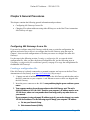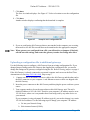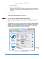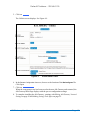
1
QS460 User Manual
USER MANUAL
GATEWAYS FOR TRANSFERRING DATA
BETWEEN DEVICENET AND MODBUS RTU
Put Bar Code Here
69-2377—01
69-2377—01
460 User Manual
Gateways for transferring data between
different protocols:
BACnet/IP
DeviceNet
EtherNet/IP
Modbus RTU
Modbus TCP
Serial
________________________________________________________________________
Real Time Automation, Inc.
150 S. Sunnyslope Rd. Suite 130
Brookfield, WI 53005
262.439.4999 (V) 262.439.4989 (F)
www.rtaautomation.com
Default IP Address – 192.168.0.100
Trademarks
BACnet is a registered trademark of the American Society of Heating, Refrigerating and AirConditioning Engineers (ASHRAE).
CoDeSys is a trademark of 3S-Smart Software Solutions GmbH.
ControlLogix, CompactLogix, & PLC-5 are registered trademarks of Rockwell Automation, Inc.
DeviceNet & EtherNet/IP are trademarks of the Open DeviceNet Vendors Association (ODVA).
MicroLogix, RSLogix 5000, and SLC are trademarks of Rockwell Automation, Inc.
Microsoft, Windows, and Internet Explorer are registered trademarks of Microsoft Corporation.
Modbus and Modbus TCP are registered trademarks of Modbus-IDA.
Twido is a trademark of Schneider Electric.
All other trademarks and registered trademarks are the property of their holders.
Revision history
Revision Revision dates
Principal changes
A
First publication
01/15/2009
Software
version
0.x
© 2009 Real Time Automation, Inc. All rights reserved.
460 Gateway User Manual
Page i
Default IP Address – 192.168.0.100
WARRANTY
Equipment Warranty:
All repair covered by this warranty must be done at Company's factory unless Company specifically directs that this
service be performed at another location. Any defect corrected within six months and found to be within this scope of
the warranty will be repaired by Company and all charges for labor and material will be borne by Company. If it is
determined that either no fault exists in Company, or the damage to be repaired was caused by negligence of
customer, its agents, employees or customers, customer agrees to pay all charges associated with each such repair.
What is not covered? (Exclusions)
Normal Wear and Tear: Periodic maintenance, repair and replacement of parts due to normal wear and tear are
excluded from coverage.
Abuse & Misuse: Defects or damage that result from: (a) improper operation, storage, misuse or abuse, accident or
neglect, such as physical damage (cracks, scratches, etc.) to the surface of the product resulting from misuse; (b)
contact with liquid, water, rain, extreme humidity or heavy perspiration, sand, dirt or the like, extreme heat, or food; or
(c) other acts which are not the fault of Real Time Automation, Inc, are excluded from coverage.
Unauthorized Service or Modification: Defects or damages resulting from service, testing, adjustment, installation,
maintenance, alteration, including without limitation, software changes, or modification in any way by someone other
than Real Time Automation, or its authorized service centers, are excluded from coverage.
Altered Products: Products or Accessories with (a) serial numbers or date tags that have been removed, altered or
obliterated; (b) mismatched board serial numbers.
Who is covered?
This warranty extends only to the first consumer purchaser, and is not transferable.
What will Real Time Automation, Inc. Do?
Real Time Automation, at its option, will at no charge repair, replace or refund the purchase price of any Products,
Accessories or Software that does not conform to this warranty. We may use functionally equivalent
reconditioned/refurbished/pre-owned or new Products, Accessories or parts. No data, software or applications added
to your Product, Accessory or Software will be reinstalled. To avoid losing such data, software and applications
please create a back up prior to requesting service.
How to Obtain Warranty Service or Other Information?
To obtain service or information, please call: Real Time Automation Customer Services 1-800-249-1612
You will receive instructions on how to ship the Products, Accessories or Software, at your expense, to a Real Time
Automation Repair Center. To obtain service, you must include: (a) a copy of your PO, complete RMA form found at
http://www.rtaautomation.com/returns/ (b) a written description of the problem; (c) the name and location of the
installation facility (if applicable) and, most importantly; (d) your address and telephone number.
460 Gateway User Manual
Page ii
Default IP Address – 192.168.0.100
What Other Limitations Are There?
ANY IMPLIED WARRANTIES, INCLUDING WITHOUT LIMITATION THE IMPLIED WARRANTIES OF
MERCHANTABILITY AND FITNESS FOR A PARTICULAR PURPOSE, SHALL BE LIMITED TO THE DURATION
OF THIS LIMITED WARRANTY, OTHERWISE THE REPAIR, REPLACEMENT, OR REFUND AS PROVIDED
UNDER THIS EXPRESS LIMITED WARRANTY IS THE EXCLUSIVE REMEDY OF THE CONSUMER, AND IS
PROVIDED IN LIEU OF ALL OTHER WARRANTIES, EXPRESS OF IMPLIED. IN NO EVENT SHALL REAL TIME
AUTOMATION BE LIABLE, WHETHER IN CONTRACT OR TORT (INCLUDING NEGLIGENCE) FOR DAMAGES IN
EXCESS OF THE PURCHASE PRICE OF THE PRODUCT, ACCESSORY OR SOFTWARE, OR FOR ANY
INDIRECT, INCIDENTAL, SPECIAL OR CONSEQUENTIAL DAMAGES OF ANY KIND, OR LOSS OF REVENUE
OR PROFITS, LOSS OF BUSINESS, LOSS OF INFORMATION OR DATA, SOFTWARE OR APPLICATIONS OR
OTHER FINANCIAL LOSS ARISING OUT OF OR IN CONNECTION WITH THE ABILITY OR INABILITY TO USE
THE PRODUCTS, ACCESSORIES OR SOFTWARE TO THE FULL EXTENT THESE DAMAGES MAY BE
DISCLAIMED BY LAW.
Some states and jurisdictions do not allow the limitation or exclusion of incidental or consequential
damages, or limitation on the length of an implied warranty, so the above limitations or exclusions may not
apply to you. This warranty gives you specific legal rights, and you may also have other rights that vary from
state to state or from one jurisdiction to another.
Laws in the United States and other countries preserve for Real Time Automation, Inc. certain exclusive rights for
copyrighted Real Time Automation, Inc. software such as the exclusive rights to reproduce and distribute copies of
the Real Time Automation, Inc. software. Real Time Automation, Inc. software may only be copied into, used in, and
redistributed with, the Products associated with such Real Time Automation, Inc. software. No other use, including
without limitation disassembly of such Real Time Automation, Inc. software or exercise of the exclusive rights
reserved for Real Time Automation, Inc. is permitted.
460 Gateway User Manual
Page iii
Default IP Address – 192.168.0.100
Table of Contents
Chapter 1 Introduction .................................................................................................... 1
Specifications................................................................................................................. 2
Supported protocols ..................................................................................................... 3
The 460 Gateway parts ................................................................................................ 3
Additional required equipment .................................................................................. 3
Chapter 2 Installing the 460 Gateway........................................................................... 4
Setting jumpers .............................................................................................................. 4
Connecting a computer for software setup............................................................. 5
Configuring the 460 Gateway .................................................................................... 8
Modbus RTU Master configuration.......................................................................... 8
Modbus RTU Slave configuration .......................................................................... 13
Modbus TCP Client configuration ......................................................................... 17
Modbus TCP Server configuration ........................................................................ 21
EtherNet/IP Client configuration ........................................................................... 24
EtherNet/IP Server configuration........................................................................... 27
DeviceNet Master configuration .......................................................................... 30
DeviceNet Slave configuration ............................................................................. 34
BACnet/IP Client configuration ............................................................................. 38
BACnet/IP Server configuration ............................................................................ 41
Serial configuration (Modules 1 and 2) ................................................................ 45
Editing 460 Gateway Network Settings.................................................................... 50
Making Settings Take Effect....................................................................................... 52
Connecting cables ..................................................................................................... 54
Chapter 3 Troubleshooting............................................................................................ 55
Checking device status ............................................................................................. 55
Checking for solutions to common problems......................................................... 58
Chapter 4 General Procedures .................................................................................... 60
Configuring 460 Gateways from a file ..................................................................... 60
Creating a configuration file ................................................................................. 60
Uploading a configuration file to additional gateways.................................... 63
Changing IP or subnet addresses ............................................................................. 66
The IPSetup.exe........................................................................................................ 66
The Real Time Automation 460 Gateway web site ............................................ 67
Chapter 5 Panel mount dimensions............................................................................. 70
460 Gateway User Manual
Page iv
Default IP Address – 192.168.0.100
Chapter 1 Introduction
The 460 Gateway lets you control how to manipulate and control data, moving it bi-directionally
across devices with different protocols. Trusted legacy devices can now be connected to a variety
of networks using 460 Gateways. For example, PLCs (including the Twido™ PLC from
Schneider Electric), building managements systems, and energy management devices can
communicate with scales, drives, barcode readers, and sensors of every type. See Figure 1-1
below.
The 460 Gateways are easy to configure using an embedded web page from which you enter the
appropriate network addresses and then define the groups of registers to send/receive data and
the order in which the data is received.
Figur
e 1-1 460 Gateway configuration options
460 Gateway User Manual
Page 1
Default IP Address – 192.168.0.100
Specifications
Table 1-1 shows the specifications for the 460 Gateway.
Table 1-1
460 Gateway specifications
Item
Hardware description
Description
Dimensions: 11 x 8.3 x 2.54 centimeters (4.2 x 3.25 x
1 inches)
Weight: 5 ounces
Enclosure material: anodized AL
Mounting: DIN rail
Power connector: 2 pin barrel
Power requirements
12VDC at 500ma
Temperature range
0° to 70° Celsius (32° to 158° Fahrenheit)
Ports
RJ45 10/100 Base-T (Ethernet)
Refer to your 460 Quick Start
Guide for correct port
configuration. (Available ones
depend on the 460
configuration you purchased.)
For gateways with two DB-9 connectors
•
RS232 on ports 0 and 1
•
RS485 on port 0
For gateways with one DB-9 connector and one TStrip5 connector
•
DB-9 can be RS232, RS485, or
CAN/DeviceNet
•
T-Strip5 can be RS-232, RS485, or
CAN/DeviceNet
*Both ports can NOT be configured to use the same
transceiver (RS-232, RS-485, or CAN).
LEDs
Connection (link speed) and power
Some models have an additional two LEDs on the
long side of the Gateway unit that are for future use.
Supported baud rates
300 to 115.2K
Internal logic specification
IEC 61131 (CoDeSys™)
Logic types supported
Ladder Logic, Instruction List, Function Block
Programming, Structured Text, and Sequential
Function Chart
460 Gateway User Manual
Page 2
Default IP Address – 192.168.0.100
Supported protocols
The 460 Gateways connect devices with the following protocols:
•
ASCII RS232
•
ASCII RS485
•
BACnet/IP® Server
•
CANopen Slave
•
DeviceNet™ Master
•
DeviceNet Slave
•
EtherNet/IP™ Client
•
EtherNet/IP Server
•
Modbus® RTU Master
•
Modbus RTU Slave
•
Modbus TCP Client
•
Modbus TCP Server
•
Raw TCP Client
•
Raw TCP Server
If you would like more information about 460 Gateway configurations, contact Real Time
Automation, Inc. (RTA) at 262.439.4999 or www.rtaautomation.com.
The 460 Gateway parts
The 460 Gateway contains the following parts.
•
The 460 Gateway unit
•
Power cable
•
DIN rail mounting
•
Crossover cable to connect a personal computer to the Gateway unit during the initial
setup (or to change settings)
•
Null modem cable (two female connectors) to use during debugging, if necessary
•
A CD with the user manuals and utilities
Additional required equipment
You need to connect a personal computer to the 460 Gateway just during the initial software
setup or if you need to change settings because of a device change.
You must supply the cables to use for communications after the setup is complete.
460 Gateway User Manual
Page 3
Default IP Address – 192.168.0.100
Chapter 2 Installing the 460 Gateway
Before the 460 Gateway can transfer data, you need to do the following tasks:
•
Optionally set jumper switches for RS232, RS485, or CAN operations on the ports (460
EDX only)
•
Connect a personal computer, temporarily, to the 460 Gateway in order to complete the
software setup
•
Make software selections for the Gateway
o After the computer is connected, configure the Communication Modules, starting
on page 8.
o When all the necessary Communication Modules are configured, continue with
Editing the 460 Gateway Network Settings on page 50.
o When you have finished setting up or making any desired changes to the 460
Gateway’s configuration, continue with Making Settings Take Effect on page 52.
•
Install the Gateway hardware
In addition to these tasks, you may need to make some additional changes on the devices to
which you are connecting the 460 Gateway. For example, if you are connecting to a PLC, you
should define tags for sending and receiving data and define ladder logic to clear the data after
the PLC receives data via the 460 Gateway. Other devices may require similar tasks.
Setting jumpers
Note: Skip this section unless you have a 460 EDX Gateway and want Port 0 or Port 1 to
change from the current settings. The factory default port settings on the 460 EDX
Gateway are for Port 0 to be set for RS485 and Port 1 to be set for RS232.
Most 460 Gateways are shipped with port settings already configured. In these cases, please skip
this section and continue on with the following section, Connecting a computer for software
setup on page 5. However, if you have a 460 EDX Gateway, you may want to change these port
settings. Other 460 Gateways cannot be modified to change the port settings. The default
port settings on the 460 EDX Gateway are for Port 0 to be set for RS485 and Port 1 to be set for
RS232. However, you can modify a port to use CAN (or return a port setting to RS 232 or
RS485) by changing the jumpers on the Gateway unit. If you are satisfied with the port settings,
skip this section and continue with the following section. Both ports cannot be set for the same
type of communications.
460 Gateway User Manual
Page 4
Default IP Address – 192.168.0.100
Note: Only one RS232, RS485, or CAN port setting can be active per unit. For example, a
unit cannot have two ports set for RS232 or two ports set for CAN.
To change port settings on the 460 EDX Gateway, use the following steps.
1. No cables should be connected to the Gateway unit. If this unit has been in use and you
are making a change, disconnect the power cable and any communications cables from
the Gateway unit.
2. Remove the two small Phillips-head screws from each long side (no connectors) of the
Gateway unit.
3. Remove the green T-Strip5 connector. Slide the cover off towards the ports. The jumpers
are just behind the ports.
4. Move the jumper shunts to reflect the desired settings. See Figure 2-1.
PORT 0
T-Strip
RS232
JP3
PORT 0
T-Strip
JP3
HSR
JP20
JP21
JP18
JP22
JP19
Pin 1
JP28
JP27
- Required
- Optional
FD – Full Duplex
JP2
PIN – Power Input
T-Strip RS232
Jumper
Configuration
DB9
RS232
Jumper
Configuration
CAN
PORT 0
T-Strip
JP17
JP20
PORT 1
DB9 JP4
JP6
JP7
JP8
JP11
JP12
JP13
JP14
JP15
JP16
RS485
JP3
JP17
HSR – High Slew Rate Control
120T – 120 Ohm Termination
RS232
JP5
JP9
JP10
Pin 1
- Required
- Optional
FD – Full Duplex
PIN – Power Input
HSR – High Slew Rate Control
120T – 120 Ohm Termination
JP17
JP20
JP21
JP18
JP22
FD
FD
JP28
FD
FD
JP27
JP21
JP18
JP22
Pin 1
JP19
- Required
- Optional
JP28
FD – Full Duplex
JP2
T-Strip RS485
Jumper
Configuration
PORT 1
DB9 JP4
JP6
JP7 FD
JP8
JP11
JP12 FD
JP13
JP14
PIN
JP15
JP16
DB9
RS485
Jumper
Configuration
Figure 2-1
JP2
PIN – Power Input
HSR – High Slew Rate Control
120T – 120 Ohm Termination
RS485
Pin 1
- Required
- Optional
FD – Full Duplex
PIN – Power Input
HSR – High Slew Rate Control
120T – 120 Ohm Termination
FD – Full Duplex
HSR – High Slew Rate Control
120T – 120 Ohm Termination
CAN
JP4
JP6
JP7
JP8
JP11
JP12
JP13
JP14
JP15
JP16
JP5
Pin 1
- Required
- Optional
PIN – Power Input
PORT 1
DB9
JP9
JP27
PIN
120T
T-Strip
CAN Jumper
Configuration
FD
JP10
JP19
DB9
CAN Jumper
Configuration
GND
JP5
GND
JP9
Pin 1
- Required
- Optional
PIN
JP10
FD – Full Duplex
PIN – Power Input
HSR – High Slew Rate Control
120T – 120 Ohm Termination
Jumper settings
5. Replace the Gateway unit’s cover. Replace the four screws. Replace the green T-Strip5
connector.
Connecting a computer for software setup
Before performing the initial software setup, you must connect a computer with a web browser to
the 460 Gateway. Use the following steps to connect the computer and to access the embedded
web site where you make your software selections.
1. Connect one end of the Ethernet crossover cable to the 460 Gateway and the other end to
the RJ45 connector on your computer.
460 Gateway User Manual
Page 5
Default IP Address – 192.168.0.100
2. Insert the power connector to the 460 gateway unit, and then plug the power cord into a
power source.
3. Launch the web browser. In the address window, enter
http://192.168.0.100
Press Enter
The RTA 460 Gateway Main Page displays. See Figure 2-2.
For illustration purposes, this manual refers to example screens from the 460EDX Gateway.
Other 460 Gateway versions have similar screens.
Note: If the web page does not display, check the following settings:
The web page does not display when the computer is on a wireless network because
of subnet selections. Use either the crossover cable or a hub/switch on the same
subnet.
Verify that your web browser is not set for a proxy server. If you are using Internet
Explorer, check Internet Options/Connections/LAN Settings. Make sure the check
box is checked for Automatically detect settings and the check box is empty (not
checked) next to the Use a proxy server for your LAN option.
Figure 2-2
460 Gateway User Manual
460 Gateway Main Page
Page 6
Default IP Address – 192.168.0.100
Note: If this is not the first time that this 460 Gateway has been configured, Figure 2-2
displays different modules.
4. Click on Edit next to the Description module on the RTA Gateway Main Page. See
Figure 2-2.
The RTA 460 Edit Description screen displays. See Figure 2-3.
5. Enter a description of up to 80 characters for this particular 460 Gateway. In this
example, the 460 Gateway is a test site for a water flow meter.
6. Click Save.
The 460 Gateway Main Page displays with the edited description.
Figure 2-3
460 Gateway User Manual
RTA 460 Edit Description
Page 7
Default IP Address – 192.168.0.100
Configuring the 460 Gateway
The 460 Gateway always acts as at least two devices at a time (for example, a Modbus RTU
Master and a serial device). Therefore, you must always configure at least two Communication
Modules. After the computer is connected to the 460 Gateway, refer to the following applicable
sections to configure your particular 460 Gateway.
•
Modbus® RTU Master configuration on page 8.
•
Modbus RTU Slave configuration on page 13.
•
Modbus TCP Client configuration on page 17.
•
Modbus TCP Server configuration on page 21.
•
EtherNet/IP™ Client configuration on page 24.
•
EtherNet/IP Server configuration on page 27.
•
DeviceNet™ Master configuration on page 30.
•
DeviceNet Slave configuration on page 34.
•
BACnet/IP® Client configuration on page 38.
•
BACnet/IP Server configuration on page 41.
•
Serial Devices configuration on page 45.
When all the necessary Communication Modules are configured, continue with Editing 460
Gateway Network Settings on page 50.
When you have finished setting up or making any desired changes to the 460 Gateway’s
configuration, continue with Making Settings Take Effect on page 52.
For illustration purposes, this manual refers to example screens from the 460EDX Gateway.
Other 460 Gateway versions have similar screens.
Modbus RTU Master configuration If your version of the 460 Gateway requires your gateway to act as a Modbus RTU Master, use
the following steps to configure the gateway. At least two Communication Modules must be
configured.
1. Click on Edit next to the Selected Communication Modules on the RTA Gateway
Main Page. See Figure 2-2.
The Communication Module Configuration screen displays. See Figure 2-4.
460 Gateway User Manual
Page 8
Default IP Address – 192.168.0.100
Note: The Edit buttons are grayed out when the task applies to a different 460
Gateway version than you purchased. Please contact Real Time
Automation, Inc. (RTA) at 262.439.4999 or www.rtaautomation.com for more
information about 460 Gateway configurations.
Figure 2-4
Communication Module Configuration screen
2. Click on Edit next to next to Modbus RTU Master.
The Enabled? prompt displays. See Figure 2-5.
460 Gateway User Manual
Page 9
Default IP Address – 192.168.0.100
Figure 2-5
Enable Modbus RTU Master configuration
3. Click on the Enabled? checkbox.
The Module’s Detail options expand when enabled. See Figure 2-6.
Figure 2-6
Modbus RTU Master configuration details
4. Select the appropriate communication options from the drop-down menus.
Note: Only one RS232, RS485, or CAN port setting can be active per unit. For example, a
unit cannot have two ports set for RS232 or two ports set for CAN. If the same mode
is selected for two communication modules, a message similar to Figure 2-7 displays.
Figure 2-7
Serial port incompatibility error
5. Click on Save.
The selections stay visible on the Communication Module Configuration screen, although
they are grayed out (until you select Edit again). See Figure 2-8.
460 Gateway User Manual
Page 10
Default IP Address – 192.168.0.100
Figure 2-8
Modbus RTU Master configuration details selected
For Your Information: Familiar users can make all desired communication
module edits before completing the external device list for the master/client
devices. The order of the configuration steps do not matter as long as the
communication module is enabled.
6. Click on the Return to Main
button. The RTA 460 Gateway Main Page displays with
a Client Module Configuration option. See Figure 2-9.
Figure 2-9
Modbus RTU Master Client Module Configuration
7. Click on Edit next to the Client Module Configuration.
The External Device Configuration screen displays.
460 Gateway User Manual
Page 11
Default IP Address – 192.168.0.100
8. For each new Device Buffer that should be enabled (1-32), click on the Add Remote
Modbus RTU Slave button.
9. Click Edit in the Action column. See Figure 2-10.
Figure 2-10
Modbus RTU Master registers and program tags
10. Enter the Save Address and select the data types from the drop-down menus for the
registers. Enter the address and length for each data type in this Device Buffer.
11. Select Save. The Master and Client Module External Device List re-displays with the
information entered for that Device Buffer. See Figure 2-11. To add another Device
Buffer, click on the Add Remote Modbus RTU Slave button and then edit that buffer’s
settings.
460 Gateway User Manual
Page 12
Default IP Address – 192.168.0.100
Figure 2-11
Modbus RTU Master data selections
12. When you have finished editing device buffers for the Modbus RTU Server, click on
The RTA 460 Gateway Main Page displays.
Main
.
Modbus RTU Slave configuration If your version of the 460 Gateway requires your gateway to act as a Modbus RTU Slave, use the
following steps to configure the gateway. At least two Communication Modules must be
configured.
1. Click on Edit next to the Selected Communication Modules on the RTA 460 Gateway
Main Page. See Figure 2-2.
The Communication Module Configuration screen displays. See Figure 2-12.
Note: The Edit buttons are grayed out when the task applies to a different 460
Gateway version than you purchased. Please contact Real Time
Automation, Inc. (RTA) at 262.439.4999 or www.rtaautomation.com for more
information about 460 Gateway configurations.
460 Gateway User Manual
Page 13
Default IP Address – 192.168.0.100
Figure 2-12
Communication Module Configuration screen
2. Click on Edit
next to Modbus RTU Slave.
The Enabled? prompt displays. See Figure 2-13.
Figure 2-13
460 Gateway User Manual
Enable Modbus RTU Slave configuration
Page 14
Default IP Address – 192.168.0.100
3. Click on the Enabled? checkbox.
The Module’s Detail options expand when enabled. See Figure 2-14.
Figure 2-14
Modbus RTU Slave configuration details
4. Select the appropriate options from the drop-down menus.
Note: Only one RS232, RS485, or CAN port setting can be active per unit. For example, a
unit cannot have two ports set for RS232 or two ports set for CAN. If the same mode
is selected for two communication modules, a message similar to Figure 2-15
displays.
Figure 2-15
Serial port incompatibility error
5. Click on Save.
The selections stay visible on the Communication Module Configuration screen, although
they are grayed out. See Figure 2-16. To change these settings, click on Edit
next to
Modbus RTU Slave again to make any necessary changes.
460 Gateway User Manual
Page 15
Default IP Address – 192.168.0.100
Figure 2-16
Modbus RTU configuration details selected
For Your Information: Familiar users can make all desired communication
module edits before leaving this screen.
6. Click on the Return to Main
button. The RTA 460 Gateway Main Page displays with
the updated Modbus RTU Slave information. See Figure 2-17.
Figure 2-17
460 Gateway User Manual
Modbus RTU Slave Module Configuration
Page 16
Default IP Address – 192.168.0.100
Modbus TCP Client configuration If your version of the 460 Gateway requires your gateway to act as a Modbus TCP Client, use
the following steps to configure the gateway. At least two Communication Modules must be
configured.
1. Click on Edit next to the Selected Communication Modules on the RTA 460 Gateway
Main Page. See Figure 2-2.
The Communication Module Configuration screen displays. See Figure 2-18.
Note: The Edit buttons are grayed out when the task applies to a different 460
Gateway version than you purchased. Please contact Real Time
Automation, Inc. (RTA) at 262.439.4999 or www.rtaautomation.com for more
information about 460 Gateway configurations.
Figure 2-18
Communication Module Configuration screen
2. Click on Edit
next to Modbus TCP Client.
The Enabled? prompt displays. See Figure 2-19.
460 Gateway User Manual
Page 17
Default IP Address – 192.168.0.100
Figure 2-19
Enable Modbus TCP Client configuration
3. Click on the Enabled? checkbox.
The Module’s Detail options expand when enabled. See Figure 2-20.
Figure 2-20
Modbus TCP Client configuration details
4. Click on Save.
For Your Information: Familiar users can make all desired communication
module edits before leaving this screen.
5. Click on the Return to Main
button. The RTA 460 Gateway Main Page displays with
a Client Module Configuration option. See Figure 2-21.
460 Gateway User Manual
Page 18
Default IP Address – 192.168.0.100
Figure 2-21
Modbus TCP Client Module Configuration
6. Click on Edit next to the Client Module Configuration.
The External Device Configuration screen displays. See Figure 2-22.
Figure 2-22
External Device Configuration screen
7. For each new Device Buffer that should be enabled (1-32), click on the Add Remote
Modbus TCP Server button.
8. Click Edit in the Action column. See Figure 2-23.
460 Gateway User Manual
Page 19
Default IP Address – 192.168.0.100
Figure 2-23
Modbus TCP Client registers and program tags
9. Enter the Server IP Address and Unit ID. Select the data types (RegType) from the dropdown menus for the registers. Enter the address and length for each data type in this
Device Buffer.
10. Select Save. The Master and Client Module External Device List re-displays with the
information entered for that Device Buffer. See Figure 2-24. To add another Device
Buffer, click on the Add Remote Modbus TCP Server button and then edit that buffer’s
settings.
460 Gateway User Manual
Page 20
Default IP Address – 192.168.0.100
Figure 2-24
Modbus TCP Client data selections
11. When you have finished editing device buffers for the Modbus TCP Client, click on
The RTA 460 Gateway Main Page displays.
Main
.
Modbus TCP Server configuration If your version of the 460 Gateway requires your gateway to act as a Modbus TCP Server, use
the following steps to configure the gateway. At least two Communication Modules must be
configured.
1. Click on Edit next to the Selected Communication Modules on the RTA 460 Gateway
Main Page. See Figure 2-2.
The Communication Module Configuration screen displays. See Figure 2-25.
Note: The Edit buttons are grayed out when the task applies to a different 460
Gateway version than you purchased. Please contact Real Time
Automation, Inc. (RTA) at 262.439.4999 or www.rtaautomation.com for more
information about 460 Gateway configurations.
460 Gateway User Manual
Page 21
Default IP Address – 192.168.0.100
Figure 2-25
Communication Module Configuration screen
2. Click on Edit
next to Modbus TCP Server.
The Enabled? prompt displays. See Figure 2-26.
Figure 2-26
460 Gateway User Manual
Enable Modbus TCP Server configuration
Page 22
Default IP Address – 192.168.0.100
3. Click on the Enabled? checkbox.
4. Click on Save.
For Your Information: Familiar users can make all desired communication
module edits before leaving this screen.
5. Click on the Return to Main
button. The RTA 460 Gateway Main Page displays with
the updated Modbus TCP Server information. See Figure 2-27.
Figure 2-27
460 Gateway User Manual
Modbus TCP Server Configuration
Page 23
Default IP Address – 192.168.0.100
EtherNet/IP Client configuration If your version of the 460 Gateway requires your gateway to act as an EtherNet/IP Client, use the
following steps to configure the gateway. At least two Communication Modules must be
configured.
1. Click on Edit next to the Selected Communication Modules on the RTA 460 Gateway
Main Page. See Figure 2-2.
The Communication Module Configuration screen displays. See Figure 2-28.
Note: The Edit buttons are grayed out when the task applies to a different 460
Gateway version than you purchased. Please contact Real Time
Automation, Inc. (RTA) at 262.439.4999 or www.rtaautomation.com for more
information about 460 Gateway configurations.
Figure 2-28
460 Gateway User Manual
Communication Module Configuration screen
Page 24
Default IP Address – 192.168.0.100
2. Click on Edit
next to EtherNet/IP Client.
The Enabled? prompt displays. See Figure 2-29.
Figure 2-29
Enable EtherNet/IP Client configuration
3. Click on the Enabled? checkbox.
The Module’s Detail options expand when enabled. See Figure 2-30.
Figure 2-30
EtherNet/IP Client configuration details
4. Click on Save.
For Your Information: Familiar users can make all desired communication
module edits before leaving this screen.
460 Gateway User Manual
Page 25
Default IP Address – 192.168.0.100
5. Click on the Return to Main
button. The RTA 460 Gateway Main Page displays with
a Client Module Configuration option. See Figure 2-31.
Figure 2-31
EtherNet/IP Client Module Configuration
6. Click on Edit next to the Client Module Configuration.
The External Device Configuration screen displays. See Figure 2-32.
460 Gateway User Manual
Page 26
Default IP Address – 192.168.0.100
Figure 2-32
External Device Configuration screen
7. To enable a Device Buffer, click on the Add Remote Ethernet/IP Server button.
8. Click Edit in the Action column.
9. Enter the Device Address. Select the data types (RegType) from the drop-down menus
for the registers. Enter the registers and program tags for each data type in this Device
Buffer.
10. Select Save. The Master and Client Module External Device List re-displays with the
information entered for that Device Buffer. To add another Device Buffer, click on the
Add Remote Ethernet/IP Server button and then edit that buffer’s settings.
11. When you have finished enabling Device Buffers for the EtherNet/IP Client, click on
The RTA 460 Gateway Main Page displays.
Main
.
EtherNet/IP Server configuration If your version of the 460 Gateway requires your gateway to act as an EtherNet/IP Server, use
the following steps to configure the gateway. At least two Communication Modules must be
configured.
460 Gateway User Manual
Page 27
Default IP Address – 192.168.0.100
1. Click on Edit next to the Selected Communication Modules on the RTA 460 Gateway
Main Page. See Figure 2-2.
The Communication Module Configuration screen displays. See Figure 2-34.
Note: The Edit buttons are grayed out when the task applies to a different 460
Gateway version than you purchased. Please contact Real Time
Automation, Inc. (RTA) at 262.439.4999 or www.rtaautomation.com for more
information about 460 Gateway configurations.
Figure 2-34
Communication Module Configuration screen
2. Click on Edit
next to Ethernet/IP Server.
The Enabled? prompt displays. See Figure 2-35.
460 Gateway User Manual
Page 28
Default IP Address – 192.168.0.100
Figure 2-35
Enable EtherNet/IP Server configuration
3. Click on the Enabled? checkbox.
4. Click on Save.
For Your Information: Familiar users can make all desired communication
module edits before leaving this screen.
5. Click on the Return to Main
button. The RTA 460 Gateway Main Page displays with
the updated EtherNet/IP Server information. See Figure 2-36.
460 Gateway User Manual
Page 29
Default IP Address – 192.168.0.100
Figure 2-36
EtherNet/IP Server Configuration
DeviceNet Master configuration If your version of the 460 Gateway requires your gateway to act as a DeviceNet Master, use the
following steps to configure the gateway. At least two Communication Modules must be
configured.
1. Click on Edit next to the Selected Communication Modules on the RTA 460 Gateway
Main Page. See Figure 2-2.
The Communication Module Configuration screen displays. See Figure 2-37.
Note: The Edit buttons are grayed out when the task applies to a different 460
Gateway version than you purchased. Please contact Real Time
Automation, Inc. (RTA) at 262.439.4999 or www.rtaautomation.com for more
information about 460 Gateway configurations.
460 Gateway User Manual
Page 30
Default IP Address – 192.168.0.100
Figure 2-37
Communication Module Configuration screen
2. Click on Edit next to next to DeviceNet Master.
The Enabled? prompt displays. See Figure 2-38.
Figure 2-38
Enable DeviceNet Master configuration
3. Click on the Enabled? checkbox.
The Module’s Detail options expand when enabled. See Figure 2-39.
460 Gateway User Manual
Page 31
Default IP Address – 192.168.0.100
Figure 2-39
DeviceNet Master configuration details
4. Select the appropriate communication options from the drop-down menus.
5. Click on Save.
The selections stay visible on the Communication Module Configuration screen, although
they are grayed out (until you select Edit again). See Figure 2-40.
Figure 2-40
DeviceNet Master configuration details selected
For Your Information: Familiar users can make all desired communication
module edits before completing the external device list for the master/client
devices. The order of the configuration steps do not matter as long as the
communication module is enabled.
6. Click on the Return to Main
button. The RTA 460 Gateway Main Page displays with
a Client Module Configuration option. See Figure 2-41.
460 Gateway User Manual
Page 32
Default IP Address – 192.168.0.100
Figure 2-41
DeviceNet Master Client Module Configuration
7. Click on Edit next to the Client Module Configuration.
The External Device Configuration screen displays. See Figure 2-42.
Figure 2-42
External Device Configuration screen
8. Click Edit in the Action column.
9. Enter the slave’s MAC ID and the Assembly Length for Data In and Data Out.
10. Select Save. The Master and Client Module External Device List re-displays with the
information entered for that Device Buffer. See Figure 2-43. To add another Device
460 Gateway User Manual
Page 33
Default IP Address – 192.168.0.100
Buffer, click on the Add Remote DeviceNet Slave button and then edit that buffer’s
settings.
Figure 2-43
DeviceNet Master data selections
11. When you have finished editing device buffers for the DeviceNet Master, click on
The RTA 460 Gateway Main Page displays.
Main
.
DeviceNet Slave configuration If your version of the 460 Gateway requires your gateway to act as a DeviceNet Slave, use the
following steps to configure the gateway. At least two Communication Modules must be
configured.
1. Click on Edit next to the Selected Communication Modules on the RTA 460 Gateway
Main Page. See Figure 2-2.
The Communication Module Configuration screen displays. See Figure 2-44.
Note: The Edit buttons are grayed out when the task applies to a different 460
Gateway version than you purchased. Please contact Real Time
Automation, Inc. (RTA) at 262.439.4999 or www.rtaautomation.com for more
information about 460 Gateway configurations.
460 Gateway User Manual
Page 34
Default IP Address – 192.168.0.100
Figure 2-44
Communication Module Configuration screen
2. Click on Edit
next to DeviceNet Slave.
The Enabled? prompt displays. See Figure 2-45.
460 Gateway User Manual
Page 35
Default IP Address – 192.168.0.100
Figure 2-45
Enable DeviceNet Slave configuration
3. Click on the Enabled? checkbox.
The Module’s Detail options expand when enabled. See Figure 2-46.
Figure 2-46
DeviceNet Slave configuration details
4. Select the appropriate options from the drop-down menus.
5. Click on Save.
The selections stay visible on the Communication Module Configuration screen, although
they are grayed out. See Figure 2-47. To change these settings, click on Edit
next to
DeviceNet Slave again to make any necessary changes.
460 Gateway User Manual
Page 36
Default IP Address – 192.168.0.100
Figure 2-47
DeviceNet Slave configuration details selected
For Your Information: Familiar users can make all desired communication
module edits before leaving this screen.
6. Click on the Return to Main
button. The RTA 460 Gateway Main Page displays with
the updated DeviceNet Slave information. See Figure 2-48.
Figure 2-48
460 Gateway User Manual
DeviceNet Slave Module Configuration
Page 37
Default IP Address – 192.168.0.100
BACnet/IP Client configuration If your version of the 460 Gateway requires your gateway to act as a BACnet/IP Client, use the
following steps to configure the gateway. At least two Communication Modules must be
configured.
1. Click on Edit next to the Selected Communication Modules on the RTA 460 Gateway
Main Page. See Figure 2-2.
The Communication Module Configuration screen displays. See Figure 2-49.
Note: The Edit buttons are grayed out when the task applies to a different 460
Gateway version than you purchased. Please contact Real Time
Automation, Inc. (RTA) at 262.439.4999 or www.rtaautomation.com for more
information about 460 Gateway configurations.
Figure 2-49
Communication Module Configuration screen
2. Click on Edit
next to BACnet Client.
The Enabled? prompt displays. See Figure 2-50.
460 Gateway User Manual
Page 38
Default IP Address – 192.168.0.100
Figure 2-50
Enable BACnet/IP Client configuration
3. Click on the Enabled? checkbox.
4. Click on Save.
For Your Information: Familiar users can make all desired communication
module edits before leaving this screen.
5. Click on the Return to Main
button. The RTA 460 Gateway Main Page displays with
a Client Module Configuration option. See Figure 2-51.
460 Gateway User Manual
Page 39
Default IP Address – 192.168.0.100
Figure 2-51
BACnet/IP Client Module Configuration
6. Click on Edit next to the Client Module Configuration.
The External Device Configuration screen displays.
7. Click Edit in the Action column. See Figure 2-52.
460 Gateway User Manual
Page 40
Default IP Address – 192.168.0.100
Figure 2-52
External Device Configuration screen
8. Enter the Device Address. Enter the registers and program tags for each data type in this
Device Buffer.
9. Select Save. The Master and Client Module External Device List re-displays with the
information entered for that Device Buffer. To add another Device Buffer, click on the
Add Remote BACnet/IP Server button and then edit that buffer’s settings.
10. When you have finished enabling Device Buffers for the BACnet/IP Client, click on
The RTA 460 Gateway Main Page displays.
Main
.
BACnet/IP Server configuration If your version of the 460 Gateway requires your gateway to act as a BACnet/IP Server, use the
following steps to configure the gateway. At least two Communication Modules must be
configured.
1. Click on Edit next to the Selected Communication Modules on the RTA 460 Gateway
Main Page. See Figure 2-2.
The Communication Module Configuration screen displays. See Figure 2-54.
Note: The Edit buttons are grayed out when the task applies to a different 460
Gateway version than you purchased. Please contact Real Time
460 Gateway User Manual
Page 41
Default IP Address – 192.168.0.100
Automation, Inc. (RTA) at 262.439.4999 or www.rtaautomation.com for more
information about 460 Gateway configurations.
Figure 2-54
Communication Module Configuration screen
2. Click on Edit
next to BACnet Server.
The Enabled? prompt displays. See Figure 2-55.
460 Gateway User Manual
Page 42
Default IP Address – 192.168.0.100
Figure 2-55
Enable BACnet/IP configuration
3. Click on the Enabled? checkbox.
The Module’s Detail options expand when enabled. See Figure 2-56.
Figure 2-56
BACnet/IP Server configuration details
4. Enter the appropriate Device Instance number and descriptions.
5. Click on Save.
The selections stay visible on the Communication Module Configuration screen, although
they are grayed out. See Figure 2-57. To change these settings, click on Edit
next to
BACnet Server again to make any necessary changes.
460 Gateway User Manual
Page 43
Default IP Address – 192.168.0.100
Figure 2-57
BACnet/IP Server configuration details selected
For Your Information: Familiar users can make all desired communication
module edits before leaving this screen.
6. Click on the Return to Main
button. The RTA 460 Gateway Main Page displays with
the updated BACnet/IP Server information. See Figure 2-58.
Figure 2-58
460 Gateway User Manual
BACnet/IP Server Module Configuration
Page 44
Default IP Address – 192.168.0.100
Serial configuration (Modules 1 and 2) If your version of the 460 Gateway requires your gateway to act as a serial device, use the
following steps to configure the gateway. If you are connecting the 460 Gateway to two different
serial devices, repeat these directions to configure Serial Module 2.
Since the 460 Gateway translates data between devices with different protocols, at least two
Communication Modules must be configured.
1. Click on Edit next to the Selected Communication Modules on the RTA 460 Gateway
Main Page. See Figure 2-2.
The Communication Module Configuration screen displays. See Figure 2-59.
Note: The Edit buttons are grayed out when the task applies to a different 460
Gateway version than you purchased. Please contact Real Time
Automation, Inc. (RTA) at 262.439.4999 or www.rtaautomation.com for more
information about 460 Gateway configurations.
Figure 2-59
460 Gateway User Manual
Communication Module Configuration screen
Page 45
Default IP Address – 192.168.0.100
2. Click on Edit next to next to Serial Module 1 (or Serial Module 2).
The Enabled? prompt displays. See Figure 2-60.
Figure 2-60
Enable Serial Module configuration
3. Click on the Enabled? checkbox.
The Module’s Detail options expand when enabled. See Figure 2-61.
4. Select the appropriate communication options.
Data flow is controlled in three ways: maximum message length, receive character
timeout, and delimiters. You can use any combination (or none) of these methods.
For Your Information: The Device Status and Summary button on the 460
Gateway’s Main Web page displays the data messages transmitted and the
method that terminated that message, which aides in troubleshooting.
460 Gateway User Manual
Page 46
Default IP Address – 192.168.0.100
Step
Step
Step 4c
Step
Step 4e
Step 4f
Figure 2-61
Serial Module configuration details
a. Enter the maximum message length before the 460 Gateway stops receiving a
particular message from the device.
b. Enter a value 10 to 60000 milliseconds to enable the receive character timeout. If
the 460 should never receive messages from the device (printer, sign, etc.), enter 0
to disable this timeout. However, if you want the 460 Gateway to poll a device
periodically regardless of how much data is accumulated, a value (other than 0)
here sends the data and then clears the buffer out after the amount of time you
select. For example, if you enter a value of 1000, the serial device sends data to
the 460 Gateway every 1 second. Even if it was in the middle of the transmission,
all data from the buffer is sent to the 460 Gateway.
c. Using delimiters is the best way to control your data. If the serial device can
output delimiters, select the correct incoming start and/or end delimiter
information for data going from the ASCII device to the 460 Gateway. If the
serial device can process incoming delimiters, select the correct outgoing start
and/or end delimiter information for data going from the 460 Gateway to the
ASCII device. The bytes should NOT be the same for both start and end.
If no delimiters are possible or desired, select Unused from the top of the dropdown menu(s).
If you do not want the start or end delimiters to be sent with the data, check the
Discard all delimiter byte(s) box.
d. Select the port that the device uses to connect to the 460 Gateway.
e. Select the appropriate communications mode.
f. Select the correct transmission settings from the menus.
460 Gateway User Manual
Page 47
Default IP Address – 192.168.0.100
Note: Only one RS232, RS485, or CAN port setting can be active per unit. For example, a
unit cannot have two ports set for RS232 or two set forRS485 (regardless of duplex
settings). If the same mode is selected for two communication modules, a message
similar to Figure 2-62 displays.
Figure 2-62
Serial port incompatibility error
5. Click on Save.
The selections stay visible on the Communication Module Configuration screen, although
they are grayed out (until you select Edit again). See Figure 2-63.
Figure 2-63
Serial Module configuration details selected
For Your Information: Familiar users can make all desired communication
module edits before completing the external device list for the master/client
devices. The order of the configuration steps do not matter as long as the
communication module is enabled.
460 Gateway User Manual
Page 48
Default IP Address – 192.168.0.100
6. Click on the Return to Main
button. The RTA 460 Gateway Main Page displays with
a Client Module Configuration option. See Figure 2-64.
Figure 2-64
Serial Module Configuration
For Your Information: If you need to configure more than one 460 Gateway with
the same or similar settings, it may be quicker to configure the first gateway
using these directions and then save the configuration to a file to use for the
other gateway units.
Note that for gateways that are configured from a file, you still need to set
jumpers (if desired), edit the network settings, and restart the gateway to make
the settings take effect. See Configuring 460 Gateways from a file on page 60
for more information.
460 Gateway User Manual
Page 49
Default IP Address – 192.168.0.100
Editing 460 Gateway Network Settings
After the computer is connected to the 460 Gateway, use the following steps to configure the
network settings. For illustration purposes, this manual refers to example screens from the
460EDX Gateway. Other 460 Gateway versions have similar screens. See Figure 2-65.
Note: If you need to change the 460 Gateway’s IP address after the initial setup, you can
use either the folowing procedure or use the IPSetup tool on the CD shipped with
the 460 Gateway. (Refer to Changing IP or subnet addresses on page 66.
Figure 2-65
460 Gateway Main web page
1. Click on Edit
next to the 460 Network Settings section of the table.
The Network Setup screen displays. See Figure 2-66.
460 Gateway User Manual
Page 50
Default IP Address – 192.168.0.100
Step
Step
Step
Step
Figure 2-66
Network Setup screen
2. Enter the IP address that identifies the 460 Gateway to the network.
3. Enter the subnet mask that identifies which devices can communicate with the 460
Gateway.
4. Enter the default gateway to use if the device cannot be accessed directly.
5. When you are finished entering these values, click on Store Parameters.
The 460 Gateway Main web page displays.
Note: The Restore original values button causes the parameters to display that were entered
when the page loaded.
6. When you have finished making any desired changes to the 460 Gateway’s configuration,
continue with the following section, Making Settings Take Effect.
For Your Information: If you need to configure more than one 460 Gateway with
the same or similar settings, it may be quicker to configure the first gateway
using these directions and then save the configuration to a file to use for the
other gateway units.
Note that for gateways that are configured from a file, you still need to set
jumpers (if desired), edit the network settings, and restart the gateway to make
the settings take effect. See Configuring 460 Gateways from a file on page 60
for more information.
460 Gateway User Manual
Page 51
Default IP Address – 192.168.0.100
Making Settings Take Effect
Before any changes to the 460 Gateway’s configuration or network settings take effect, you must
reboot the unit. Do this before removing power from the 460 Gateway.
Use the following steps to reboot the 460 Gateway.
For illustration purposes, this manual refers to example screens from the 460EDX Gateway.
Other 460 Gateway versions have similar screens. Figure 2-67 shows an example of the 460
Gateway’s Main Page.
Figure 2-67
460 Gateway Main Page
1. From the 460 Gateway Main Page click on Utilities on the left side of the screen.
The RTA 460 Utilities screen displays. See Figure 2-68.
460 Gateway User Manual
Page 52
Default IP Address – 192.168.0.100
Figure 2-68
RTA 460 Utilities screen
2. Click on Restar toward the top of the screen.
A prompt displays asking you to verify that you want to restart the 460 Gateway.
3. Click OK.
Another prompt displays giving you the approximate time to complete the restart.
4. Click OK.
When the restart is complete, the 460 Gateway Main Page displays if your computer is on
the same subnet (or attached) to the 460 Gateway.
If your computer is not on the same subnet, the screen does not change, as you are no
longer receiving signals from the 460 Gateway.
5. If you are installing the 460 Gateway in a position that is not connected to the computer
that did the software setup, disconnect the crossover cable from the 460 Gateway and
from the computer.
Save the crossover cable with the null modem cable and the CD that was shipped with the
460 Gateway in case you need to make changes at a later time.
460 Gateway User Manual
Page 53
Default IP Address – 192.168.0.100
Connecting cables
Once the jumpers are set for the correct serial interfaces and the configuration and network
settings are selected, you only need to connect the communications cables and attach the power
cable, before verifying that data is transmitting correctly. Use the following steps to connect the
appropriate cables.
1. Mount the 460 Gateway in the desired location.
2. Connect the appropriate cable to Port 0 on the 460 Gateway and the other end to the
device that matches the protocol selected for Port 0. Do the same for Port 1. Use the
correct cables.
3. If you are connecting the 460 Gateway to a network, plug one end of a non-crossover
Ethernet cable (RJ45) to the front of the 460 Gateway. Plug the other end into the
network/switch/hub.
Note: In order to view the status of the data communications between the devices
connected to the 460 Gateway via the Gateway’s utilities, the 460 Gateway must be
connected to a network (or computer).
4. Plug the power connector into the front of the 460 Gateway. Plug the other end of the
power cord into a power supply.
You have completed installing the 460 Gateway.
460 Gateway User Manual
Page 54
Default IP Address – 192.168.0.100
Chapter 3 Troubleshooting
After the 460 Gateway is set up, it should transmit and receive data correctly. However, if it is
not working as you expect, this chapter provides the following information to help you resolve
the problem.
•
Use the 460 Gateway’s Summary and Status page to find clues to what may be causing
the problem.
•
Check Table 3-1 for possible solutions to common problems.
Checking device status
Use the use the following steps to view the 460 Gateway’s Status and Summary page.
If the 460 Gateway is already connected to a personal computer and can access the Real Time
Automation web site (factory set at http://192.168.0.100), skip to step 5.
1.
Connect one end of an Ethernet crossover cable to the 460 Gateway and the other end to
the RJ45 connector on your computer. A red Ethernet crossover cable was shipped with
the 460 Gateway.
2. Insert the power connector to the 460 Gateway and then plug the power cord into a power
source.
3. Your computer needs to be on the same subnet as this 460 Gateway unit. The unit’s
default IP address is 192.168.0.100. Therefore your computer’s IP address must be set at
192.168.0.xxx, where xxx is any number that is not being used by any other device on
your network.
If your computer is using a dynamic IP address (typical), you need to change it to a static
192.168.0.xxx address. Use the following steps to change your computer’s IP address.
a. Go into your Network Setup.
b. Select Internet Protocol (TCP/IP).
c. Click on Properties.
d. Click Use the following IP address.
e. Type in 192.168.0.10 (the last two digits are an example and can be any number
as long as it is not being used). The Subnet mask should default to 255.255.255.0.
Click OK.
4. Launch the web browser. In the address window, enter the IP address of the 460
Gateway.
Press Enter
The 460 Gateway Main Page displays. See Figure 3-1.
460 Gateway User Manual
Page 55
Default IP Address – 192.168.0.100
Note: If the web page does not display, check the following settings:
The web page does not display when the computer is on a wireless network because
of subnet selections. Use either the crossover cable or a hub/switch on the same
subnet.
Verify that your web browser is not set for a proxy server. If you are using Internet
Explorer, check Internet Options/Connections/LAN Settings. Make sure the check
box is checked for Automatically detect settings and the check box is empty (not
checked) next to the Use a proxy server for your LAN option.
Step 5
Figure 3-1
5. Click on
460 Gateway Main Page
Status and Summary
The RTA 460 Device Summary and Status screen displays. See Figure 3-2.
460 Gateway User Manual
Page 56
Default IP Address – 192.168.0.100
Figure 3-2
RTA 460 Device Summary and Status screen
6. Click Refresh or Press F5.
The values on this screen do not update automatically. Continue to click on
press F5 to see the most current status and buffer values.
Refresh
or
Check this screen for error codes or messages. This screen displays data in buffers to help
you troubleshoot any data transmission problems. Use Table 3-1 to interpret error
conditions or messages.
Note: To clear out the Value Dec, Value Hex, and Description fields without Restarting
the 460 Gateway, click on Reset Status Counters .
7. Click on
Main Page
to return to the 460 Gateway Main Page.
460 Gateway User Manual
Page 57
Default IP Address – 192.168.0.100
Checking for solutions to common problems
Use Table 3-1 to check for possible solutions to common problems.
If you are unable to resolve the issue, contact Real Time Automation, Inc. (RTA) at
262.439.4999 or www.rtaautomation.com for more assistance.
Table 3-1
Common problems and possible solutions
Problem
Possible solutions
The personal computer
cannot connect to the 460
Gateway.
Verify the 460 Gateway has power.
The web browser at IP
address 192.168.0.100
(default) does not display.
The web page does not display when the computer is
on a wireless network because of subnet selections.
Use either the crossover cable or a regular cable with a
hub/switch on the same subnet. If you can ping the 460
Gateway from the computer, then this is not the
problem.
To connect a personal computer to the 460 Gateway,
you must use either an Ethernet crossover cable or a
null modem cable. One of each of these cables was
shipped with the 460 Gateway.
Verify that your web browser is not set for a proxy
server. If you are using Internet Explorer, check
Internet Options/Connections/LAN Settings. Make sure
the check box is empty (not checked) next to the Use a
proxy server for your LAN option.
Data was transmitting, but
now it seems to have
stopped.
Check that all the cables and the power cord are secure.
Data is transmitting, but it
does not seem to be
correct.
This may be a data format (radix) problem. For
example, if you are sending ASCII data and are
displaying decimal data, all your data appears to be off
by 48. A zero value in decimal is 0x30 in hexadecimal.
The data displaying on the
Device Summary and
Status screen is not the
same as the data sent to the
end-point device.
Change how you are viewing the data (ASCII, decimal,
or hexadecimal) in your tag or register.
If data from one port is transmitting, but the other port
is not, try changing cables.
460 Gateway User Manual
Page 58
Default IP Address – 192.168.0.100
Problem
The end of the data is
being lost.
Possible solutions
You may be sending more bytes of data than you have
set in either the Maximum message length field or that
have time to transmit because of the Receive Character
Timeout field’s setting.
Or, if you are using an end delimiter, you may have a
Maximum message length field setting or Receive
Character Timeout setting that causes the data to
transmit before the end delimiter is detected. New data
transmits after the start delimiter is recognized. The
data after the buffer length restriction and before the
next start delimiter is lost.
N/A displays on the Device The port and or function is disabled for one of the
Summary and Status screen following reasons:
•
The Enabled? box for the type of protocol is not
checked on the RTA 460 Communication
Module Configuration screen.
•
The Receive Character Timeout field (in the
Serial Modules) is set to 0 on the RTA 460
Communication Module Configuration screen.
The message Waiting for
data to write displays on the
Device Summary and
Status page.
If the serial devices have sent additional data, check
that the cable(s) is fastened securely.
I do not see any serial data
in the buffer on the Device
Summary and Status
screen. The 460 Gateway is
set up and installed.
Verify that the 460 Gateway was restarted after its
initial configuration.
Verify the 460 Gateway is connected to the appropriate
devices.
Press Refresh
screen.
No data output comes from
the 460 Gateway.
on the Device Summary and Status
Output from the device may be disabled. Verify that
the Buffer Transmit Length is not set to 0 in the
applicable serial module configuration.
Check that the start and stop delimiters are different
(for serial modules).
The error has been fixed,
but the error code still
displays on the Device
Summary and Status page.
Transmit data successfully then click
Device Summary and Status screen.
460 Gateway User Manual
Refresh
on the
Page 59
Default IP Address – 192.168.0.100
Chapter 4 General Procedures
This chapter contains the following general information and procedures:
•
Configuring 460 Gateways from a file
•
Changing IP or subnet addresses using either IPSetup.exe or the Real Time Automation
460 Gateway web page
Configuring 460 Gateways from a file
If you need to configure many 460 Gateways with the same or a similar configuration, the
quickest and easiest way to do so is to configure the first 460 Gateway using the steps in
Chapter 1, then save that configuration to a file that you can use to configure the other 460
Gateways.
Use the steps in the following section, Creating a configuration file, to create the initial
configuration file. After you have the desired configuration file, use the following steps in
Uploading a configuration file to additional gateways on page 63 to copy the configuration file
to additional 460 Gateways.
Creating a configuration file If the 460 Gateway is already connected to a personal computer and can access the Real Time
Automation web site (factory set at http://192.168.0.100), skip to step 5.
1.
Connect one end of an Ethernet crossover cable to the 460 Gateway and the other end to
the RJ45 connector on your computer. A red Ethernet crossover cable was shipped with
the 460 Gateway.
2. Insert the power connector to the 460 Gateway
eway and then plug the power cord into a power
source.
3. Your computer needs to be on the same subnet as this 460 Gateway unit. The unit’s
default IP address is 192.168.0.100. Therefore your computer’s IP address must be set at
192.168.0.xxx, where xxx is any number that is not being used by any other device on
your network.
If your computer is using a dynamic IP address (typical), you need to change it to a static
192.168.0.xxx address. Use the following steps to change your computer’s IP address.
a. Go into your Network Setup.
b. Select Internet Protocol (TCP/IP).
460 Gateway User Manual
Page 60
Default IP Address – 192.168.0.100
c. Click on Properties.
d. Click Use the following IP address.
e. Type in 192.168.0.10 (the last two digits are an example and can be any number
as long as it is not being used). The Subnet mask should default to 255.255.255.0.
Click OK.
4. Launch the web browser. In the address window, enter
http://192.168.0.100
Press Enter
The 460 Gateway Main Page displays. See Figure 4-4.
Note: If the web page does not display, check the following settings:
The web page does not display when the computer is on a wireless network because
of subnet selections. Use either the crossover cable or a hub/switch on the same
subnet.
Verify that your web browser is not set for a proxy server. If you are using Internet
Explorer, check Internet Options/Connections/LAN Settings. Make sure the check
box is checked for Automatically detect settings and the check box is empty (not
checked) next to the Use a proxy server for your LAN option.
Step 5
Figure 4-4
460 Gateway User Manual
460 Gateway Main Page
Page 61
Default IP Address – 192.168.0.100
5. Click on
Utilities
The Utilities screen displays. See Figure 4-5.
Figure 4-5
RTA 460 Utilities screen
6. Click on Save Configuration
. to File
The File Download window displays. See Figure 4-6
Figure 4-6
460 Gateway User Manual
Configuration file verification
Page 62
Default IP Address – 192.168.0.100
7. Click Save.
The Save As window displays. See Figure 4-7. Select a location to save the configuration
file.
8. Click Save.
Another window displays confirming that the download is complete.
Figure 4-7
Prompt to save configuration file
9. If you are configuring 460 Gateways that are not attached to the computer you are using,
then email or save the file to media that can be transferred to the appropriate computer.
Note: When gateways are configured from a file, you still need to set jumpers (if desired),
edit the network settings, and restart the gateway to make the settings take effect.
Uploading a configuration file to additional gateways Use the following steps to configure a 460 Gateway from an existing configuration file. If you
changed jumper settings on the 460 Gateway that supplied the configuration file, you need to
change the settings on all gateways configured using the file. Refer to Setting jumpers on page 4.
If the 460 Gateway is already connected to a personal computer and can access the Real Time
Automation web site (http://192.168.0.100), skip to step 5.
1.
Connect one end of an Ethernet crossover cable to the 460 Gateway and the other end to
the RJ45 connector on your computer. A red Ethernet crossover cable was shipped with
the 460 Gateway.
2. Insert the power connector to the 460 Gateway and then plug the power cord into a power
source.
3. Your computer needs to be on the same subnet as this 460 Gateway unit. The unit’s
default IP address is 192.168.0.100. Therefore your computer’s IP address must be set at
192.168.0.xxx, where xxx is any number that is not being used by any other device on
your network.
If your computer is using a dynamic IP address (typical), you need to change it to a static
192.168.0.xxx address. Use the following steps to change your computer’s IP address.
a. Go into your Network Setup.
b. Select Internet Protocol (TCP/IP).
460 Gateway User Manual
Page 63
Default IP Address – 192.168.0.100
c. Click on Properties.
d. Click Use the following IP address.
e. Type in 192.168.0.10 (the last two digits are an example and can be any number
as long as it is not being used). The Subnet mask should default to 255.255.255.0.
Click OK.
4. Launch the web browser. In the address window, enter
http://192.168.0.100
Press Enter
The 460 Gateway Main Page displays. See Figure 4-8.
Note: If the web page does not display, check the following settings:
The web page does not display when the computer is on a wireless network because
of subnet selections. Use either the crossover cable or a hub/switch on the same
subnet.
Verify that your web browser is not set for a proxy server. If you are using Internet
Explorer, check Internet Options/Connections/LAN Settings. Make sure the check
box is checked for Automatically detect settings and the check box is empty (not
checked) next to the Use a proxy server for your LAN option.
Step 5
Figure 4-8
460 Gateway User Manual
460 Gateway Main Page
Page 64
Default IP Address – 192.168.0.100
5. Click on
Utilities
The Utilities screen displays. See Figure 4-9.
Figure 4-9
RTA 460 Utilities screen
6. In the Restore Configuration from area, browse to the location of the RtaConfig.rtax file.
Click Open.
7. Click on Restore from File.
When the configuration file has been saved to the new 460 Gateway and restarted, the
460 Gateway Main Page displays with the pre-set configuration settings.
8. To complete installing the 460 Gateway, continue with Editing 460 Gateway Network
Settings on page 50 and Making Settings Take Effect on page 52.
460 Gateway User Manual
Page 65
Default IP Address – 192.168.0.100
Changing IP or subnet addresses
After the 460 Gateway is setup and installed, you can still change IP or subnet addresses using
one of two methods. The easiest way involves using the IPSetup.exe tool on the User Manuals
and Tools CD shipped with the 460 Gateway. However, if you no longer have the CD that came
with the 460 Gateway, you can still change IP or subnet addresses using the Real Time
Automation 460 Gateway web site.
The IPSetup.exe If you have the User Manuals and Tools CD that was shipped with the 460 Gateway, use the
following steps to change the IP or subnet address. You can run this tool from your desktop, as it
does not install any files.
1. Connect one end of an Ethernet crossover cable to the 460 Gateway and the other end to
the RJ45 connector on your computer. A red Ethernet crossover cable was shipped with
the 460 Gateway. (Or, you can use a regular Ethernet cable connected to a hub or subnet
with the 460 Gateway.)
2. Insert the power connector to the 460 Gateway, and then plug the power cord into a
power source.
3. Insert the CD into the CD-ROM drive on your computer. Double-click on the Tools
folder.
Three tools display.
For Your Information: If you no longer have the CD that shipped with the 460
Gateway, download the IPSetup.exe at http://www.rtaautomation.com/support
from the Real Time Automation’s website.
4. Double-click on IPSetup.
The Real Time Automation IPSetup screen displays. See Figure 4-10.
460 Gateway User Manual
Page 66
Default IP Address – 192.168.0.100
Figure 4-10
Real Time Automation IPSetup screen
5. Click on Search Again.
The 460 Gateway units on the network display. If the crossover cable is connected
directly to your computer instead of to a hub, the 460 Gateway is the only one that
displays.
Note: If you don’t see the 460 Gateway on the right, the unit is not accessible, and you
need to look at connections to hub, router, switches, etc.
6. Change the IP, Network Mask, GateWay or DNS fields according to your network
requirements. Leave Baud rate at the default value.
7. Highlight (click on) the unit to program on the upper right side of the screen, and click
Set. After you have changed any other IP or subnet addresses (if necessary), click on
Close.
8. Close the Tools folder and remove the User Manual and Tools CD.
The Real Time Automation 460 Gateway web site If you do NOT have the User Manuals and Tools CD that was shipped with the 460 Gateway,
use the following steps to change the IP or subnet address.
1. Connect one end of an Ethernet crossover cable to the 460 Gateway and the other end to
the RJ45 connector on your computer or to a hub/switch on the same subnet. A red
Ethernet crossover cable was shipped with the 460 Gateway.
2. Insert the power connector to the 460 Gateway, and then plug the power cord into a
power source.
3. Your computer needs to be on the same subnet as the 460 Gateway. The unit’s default IP
address is 192.168.0.100. Therefore your computer’s IP address must be set at
192.168.0.xxx, where xxx is any number that is not being used by any other device on
your network.
If your computer is using a dynamic IP address (typical), you need to change it to a static
192.168.0.xxx address. Use the following steps to change your computer’s IP address.
a. Go into your Network Setup.
b. Select Internet Protocol (TCP/IP).
c. Click on Properties.
d. Click Use the following IP address.
e. Type in 192.168.0.10 (the last two digits are an example and can be any number
as long as it is not being used). The Subnet mask should default to 255.255.255.0.
Click OK.
460 Gateway User Manual
Page 67
Default IP Address – 192.168.0.100
4. Launch the web browser. In the address window, enter
http://192.168.0.100
Press Enter
The Real Time Automation 460 Gateway web page displays. See Figure 4-11.
Note: If the web page does not display, check the following settings:
The web page does not display when the computer is on a wireless network because
of subnet selections. Use either the crossover cable or a hub/switch on the same
subnet.
Verify that your web browser is not set for a proxy server. If you are using Internet
Explorer, check Internet Options/Connections/LAN Settings. Make sure the check
box is checked for Automatically detect settings and the check box is empty (not
checked) next to the Use a proxy server for your LAN option.
Step
Figure 4-11
Real Time Automation 460 Gateway Main Page
5. Go to the Network Settings area of the screen. Click on
The Network Setup screen displays. See Figure 4-12.
460 Gateway User Manual
Edit
Page 68
Default IP Address – 192.168.0.100
Step
Step
Step
Step
Figure 4-12
Network Setup screen
6. Enter the IP address that identifies the 460 Gateway to the network.
7. Enter the subnet mask that identifies which devices can communicate with the 460
Gateway.
8. Enter the default gateway to use if the device cannot be accessed directly.
9. When you are finished entering these values, click on Store Parameters.
The 460 Gateway Main web page displays.
Note: The Restore original values button causes the parameters to display that were entered
when the page loaded.
10. When you have finished making any desired changes to the 460 Gateway’s configuration,
continue with the following section, Making Settings Take Effect.
460 Gateway User Manual
Page 69
Default IP Address – 192.168.0.100
Chapter 5 Panel mount dimensions
Figure 5-1 shows the panel mount dimensions for the 460 Gateway.
Figure 5-1
460 Gateway User Manual
Panel mount dimensions
Page 70
Default IP Address – 192.168.0.100
460 Gateway User Manual
Page 71
69-2377—01
QS460 USER MANUAL
Automation and Control Solutions
Honeywell International Inc.
Honeywell Limited-Honeywell Limitée
1985 Douglas Drive North
35 Dynamic Drive
Golden Valley, MN 55422
Toronto, Ontario M1V 4Z9
customer.honeywell.com
® U.S. Registered Trademark
© 2009 Honeywell International Inc.
69-2377—01
K.K. Rev. 07-09