1
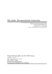
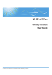
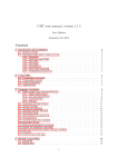
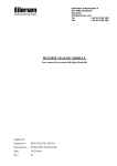
INTEGRATED SYSTEMS AND CONTROL, INC. User Manual PCM400I INTEGRATED SYSTEMS AND CONTROLS, INC. PCM400I Users Manual Revised March 28, 2001 2001 Integrated Systems and Control. Inc. PO Box 7682, Auburn, CA 95604 Phone 530-878-9038 • Fax 530-878-9137 Table of Contents General Specifications Installation Operation Service 3 5 10 12 19 2 General The PCM400I gives our PCM400 series Internet Connectivity. The PCM400I shares the programming, logging and communications features of the PCM400I with dial up capability to log on to an ISP (Internet Service Provider) and communicate via a variety of Internet protocols. The PCM400I product is a two board set. It is comprised of a CPU Board that contains the microprocessor and memory and virtually all the necessary electronic parts. The second board is the I/O Board that contains the screw terminals required to connect almost all the field wiring to the board set. The two boards are designed to be placed next to one another and be connected to each other via a 50 conductor ribbon cable. Alternately, the two boards may be placed apart by up to 36 inches to facilitate packaging flexibility. The I/O Board contains a 20 pin ribbon cable connector that is designed to drive the “outputs-only” of either a RLY80 or RLY180 relay board. We believe that the PCM400I is a product that provides the best combination of software functionality, packaging flexibility, short development cycle and low cost. The PCM400I retains the compatibility with the Modicon Modbus RTU network protocol on the second serial channel (ala the PCM400N). The PCM400I may be used as a Modbus RTU Master or Slave device on any Modbus RTU compatible network. When configured as a Network Master, up to 16 slaves may be connected to it’s RS485 network port. When configured as a Network Slave, the PCM400I may be connected to any Modbus RTU network and be used as a “Smart” network device. ISAC designed Modbus RTU network masters have expanded network functions that go beyond the standard Modbus RTU capabilities. 3 PCM400I CPU Board (on-board Modem version) PCM400I I/O Board 4 Specifications CPU Board Size: Height = 5.0”, Width = 8.8”, and Depth = 1.0”. I/O Board Size: Height = 2.2”, Width = 8.8”, and Depth = 1.0”. Input Power: 24VDC +-0.2 at 1.0 Amps (including (1) RLY180). The input power is fused at 1.25 Amps and there a power switch on the I/O Board to switch the main input power. The field terminals for connection of power are on the I/O Board (TB1). If the RLY180 Board is to be used with the control, the fuse value and the 24VDC power requirement will need to be increased by 0.4 Amp. In this case, a 1.6 Amp fuse should be used and a power supply capable of supplying >=1.6 Amps should be used. Output Power: Terminals are provided on the I/O Board for providing power for external sensors and output relays. An optional 12vdc terminal is available for external use of less than 50 milliamperes of current. A 24vdc terminal is available for powering external output relays when neither of the RLY relay boards is required. This 24vdc output is limited to a maximum current of .25 amperes. Analog Inputs: The basic board set has terminals for 6 analog inputs which may be used as either 0-5VDC, 0-20ma, 4-20ma, or 10K Thermistor temperature. A board jumper may be used to connect the input to a 250 Ohm 1% resistor for 0-20ma or 4-20ma inputs. In addition to the 6 analog inputs available for field sensors, there are two analog inputs that are used internally to monitor power supply voltages. Two Analog Inputs are reserved for measuring the system power supplies. AI#7 measures the 5 vdc supply voltage and AI#8 measures the 24 vdc supply voltage. The CPU Board is equipped with a 10 pin ribbon connector that allows the connection of one Expansion Analog Input Board to allow the addition of 8 more analog inputs (AI#9 thru AI#16). Therefore, the maximum number of field accessible analog inputs with an expansion board is 6+8=14 field useable analog inputs. Digital Inputs: The basic board set has 8 digital inputs (DI#1 thru DI#8) which are selfpowered from the 24VDC power such that only a contact closure is required to activate them. Screw terminals on the I/O Board are provided for connections. Internally these inputs may be defined for use as general purpose inputs, status inputs intended to trigger alarms if the corresponding digital output does not switch, as a timed latching input useful in logic rules to provide temporary user overrides, and for accumulating pulses such as from a power meter or flow meter. When a RLY80 or RLY180 relay boards are attached to the PCM400I, the digital status inputs of the relay board are IGNORED. All the field digital input devices must be terminated on the I/O Board. There is currently no way to expand the number of digital inputs. The Digital Inputs may be configured to function as a pulse accumulator. The Digital Input Definition programming screen include attributes for Pulse Sum Period and for a Multiplier that 5 may be used to convert flow meter and power meter output signals into measured quantities. The maximum pulse rate that can be accepted without error is 25 pulses/second. Digital Outputs: The basic board set has 8 solid state (sinking) 24VDC digital outputs terminated on the I/O Board (DO#1 thru DO#8). Each output is capable of sinking (switching to RET) a load device that requires 100ma or less. A typical load would be an interface relay with a 24VDC coil or another logic board that may use a pulse-width modulation signal to control air pressure, etc. By programming the PCM400I any or all of the 8 DO’s may be used for PWM. If a RLY80 or RLY180 relay output board is attached to the connector provided on the I/O Board, the digital output terminals of the PCM400I’s I/O Board will be redirected to operate the relays of the RLY80 or RLY180 and should not be used. When a RLY180 is connected to the PCM400I, CPU Board jumper JU15C must have a shunt installed to inform the firmware that this special board is present. This jumper must be removed when no relay board is attached or when the RLY80 relay board is used. Using the RLY180 relay board, the PCM400I can drive a maximum of 18 digital relay outputs. Analog Output: The PCM400I (optionally) provides one (1) true analog output (AO#1) which produces a self-powered 0-20ma or 4-20ma signal for driving field mounted transducers/transmitters. To use the AO, program the PCM400I’s AO#1 and specify that the output should use a true analog output rather than a PWM (pulse width modulation) type. Screw terminals are provided for connections on the I/O Board. Calibration adjustments are provided on the I/O Board, consult factory instructions before making any adjustments on the analog output Zero and Span adjust screws. To connect the AO to a load devise, connect the AO#1 terminal (I/O board, TB2- 12) to the load/transducer’s positive signal (+) terminal and connect RET (I/O board, TB2- 32) to the load/transducer’s negative signal (-) terminal. Current will flow out of the PCM400I’s AO terminal, through the load/transducer input and then back to the PCM400I’s RET. Serial Port #1, Modem Port: Serial Port #1 is a port designed to be used for a Modem or for a local laptop computer user interface. The PCM400I is normally equipped with an on-board Modem. A special order version is available to allow the use of an external Modem, consult ISAC for information about pricing and availability of this special version. When configured for Internet communications, the PCM400I can automatically maintain a full time Internet connection by dialing an ISP and logging on to the Internet. If the connection is dropped, the PCM400I will automatically re-establish the connection. For on-site startup purposes the Serial Port #2 may be temporarily configured by changing hardware jumpers to allow J3 to be used for a laptop computer to allow field re-programming. To allow this temporary access remove TB1, set JU8 to position A, and remove the JU15-B shunt jumper. In this configuration, the RS485 Modus network is disabled. 6 Serial Port #2, RS485: The PCM400I CPU Board contains a RS485 Network port that is used to connect to Modbus RTU compatible equipment. The Network connection is made at the TB1 connector. To properly enable the Networking functions of the PCM400I, the JU15B must be installed and jumper JU8 must be set to the “B” position. This Network port performs the functions of a MASTER or a SLAVE, depending on the settings of the PCM400I’s user programming. The PCM400I’s Network port is Modbus RTU compatible, such that most other commercially available Modbus RTU compatible equipment may be used with the control. The default network data speed is 9600 Baud. Contact ISAC for a list of such equipment that have been successfully used in field applications. 7 Installation PCM400I Summary of Connections The terminal strips of the PCM400I board set are mainly located on the I/O Board. Connections for serial port/Modem and the expansion connector for the use of the Expansion Analog Input Board are located on the CPU Board for electronic reasons. The following tables define the function of each of the PCM400I’s connections: CPU Board:___________________________________ TB1 (Serial Port #2, RS422/RS485, Modbus Network Port) 1 - Tx+ 2 - Tx3 - Rx+ 4 - Rx5 - COM 6 - 5vdc Note: To connect to Veris Hawkeye Power Meters, jump TB1-1 to TB1-3 and then connect to the Veris 8035/8036 plus (+) terminal. Jump TB1-2 to TB1-4 and then connect to the Veris 80358036 minus (-) teminal. Lastly, connect TB1-5 to the Veris 8035/8036 common or shield terminal. J1 (I/O Board connections) J2 (Analog Expansion for AI#9 to AI#16) J3 (unused in PCM400I standard version, used as an RS232 port for field maintenance purposes by changing the settings of JU8 and JU15-B) 1 - CD 2 - RX DATA 3 - TX DATA 4 - DTR 5 - COM 6 - n/u 7 - RTS 8 - CTS 9 - n/u 8 J4 (Serial Port #1, RS232, only available on a special external Modem version) 1 - CD 2 - RX DATA 3 - TX DATA 4 - DTR 5 - COM 6 - n/u 7 - RTS 8 - CTS 9 - n/u J5 This connector in standard PCM400I version, may be connected to an analog telephone line for connection to the on-board Modem Jumpers used to configure the CPU Board for hardware related features: JU1 - Install to enable the battery support for the memory. Remove for shipment. JU2 thru JU7 - Factory configured, DO NOT CHANGE. JU8 - Must be in the B position to enable the Modbus RS485 network feature of the PCM400I. Placed in the A position to enable maintenance RS232 port, J3. JU9 - 2-pos jumper for AI#1, B= 4-20ma, A (or no jumper)= 5vdc or Thermistor. JU10 - 2-pos jumper for AI#2, B= 4-20ma, A (or no jumper)= 5vdc or Thermistor. JU11 - 2-pos jumper for AI#3, B= 4-20ma, A (or no jumper)= 5vdc or Thermistor. JU12 - 2-pos jumper for AI#4, B= 4-20ma, A (or no jumper)= 5vdc or Thermistor. JU13 - 2-pos jumper for AI#5, B= 4-20ma, A (or no jumper)= 5vdc or Thermistor. JU14 - 2-pos jumper for AI#6, B= 4-20ma, A (or no jumper)= 5vdc or Thermistor. JU15A - (future) JU15B - Must be installed to enable the Modbus network feature of the PCM400I. Uninstalled only to disable the Modbus network and enable the maintenance RS232 port J3. JU15C - Install for use with RLY180 relay board, remove for RLY80 or none. I/O Board:___________________________________ TB1 (power input terminal strip) 1 - 24VDC (regulated) main input terminal. 2 - DC RET (return for power supply) 3 - DC RET (return for power supply) TB2 (I/O Terminations) 1 - AI#1 2 - AI#2 3 - IRET 4 - AI#3 5 - AI#4 6 - IRET 9 7 - AI#5 8 - AI#6 9 - IRET 10 - Thermistor 5VDC power supply 11 - Thermistor 5VDC power supply 12 - AO#1 4-20ma Output (optional) 13 - 12VDC sensor power (50 ma max) (optional) 14 - 12VDC sensor power (50 ma max) (optional) 15 - 24VDC power (switched, 0.25A max) 16 - 24VDC power (switched, 0.25A max) 17 - DO#1 (open collector output, sinking to RET) 18 - DO#2 (open collector output, sinking to RET) 19 - DO#3 (open collector output, sinking to RET) 20 - DO#4 (open collector output, sinking to RET) 21 - DO#5 (open collector output, sinking to RET) 22 - DO#6 (open collector output, sinking to RET) 23 - DO#7 (open collector output, sinking to RET) 24 - DO#8 (open collector output, sinking to RET) 25 - DI#1 (switch to RET to activate the input) 26 - DI#2 (switch to RET to activate the input) 27 - DI#3 (switch to RET to activate the input) 28 - DI#4 (switch to RET to activate the input) 29 - DI#5 (switch to RET to activate the input) 30 - DI#6 (switch to RET to activate the input) 31 - DI#7 (switch to RET to activate the input) 32 - DI#8 (switch to RET to activate the input) 33 - RET 34 - RET 35 - RET 36 - GREEN WIRE GND J1 (CPU Board connection) J2 (RLY80/RLY180 connection) Wiring Considerations Care should be used to route the low energy signal wiring to and from the PCM400I. The ribbon cable used to connect the CPU and I/O boards should be kept as short as possible and should be routed such that it is at least 1” away from any 24V or higher signal wires. Modbus Network Wiring Considerations 1. Network signals are low energy and low voltage signals. Care must be taken to ensure that minimum interference occurs between these wires and higher power switching signals. Any 10 2. 3. 4. 5. 6. 7. RS422 or RS485 Network should use twisted pair and shielded cabling. RS422 requires 5 conductors and a shield conductor, while RS485 requires 3 conductors and a shield conductor. The PCM400I may be connected as either RS422 or RS485. All the devices on a network MUST be configured the same, you cannot mix RS422 and RS485 on the same network wiring. The Modbus RTU type network can have only one MASTER device and up to 32 SLAVE devices. The total length of the Modbus Network, end to end, must be less than 4000 Meters. For RS422, the Tx+ and Tx- signals of the Network MASTER are wired to all of the SLAVE’s Rx+ and Rx- terminals, respectively (Master Tx+ to Slave Rx+, etc., in daisy chain fashion). Similarly, the Rx+ and Rx- signals of the Network MASTER are wired to all of the SLAVE’s Tx+ and Tx- terminals, respectively (Master Rx+ to Slave Tx+, etc., in daisy chain fashion). A signal GROUND wire must also be run to ensure that all the devices have a common Return signal. All devices on the Network must also be well GROUNDED to a common green-wire ground (Earth Ground). Lastly, a shield around the Network conductors must be terminated to Earth Ground (not signal ground). For RS485, the Tx+ is tied to the Rx+ signals of the Network MASTER and then connected to the SLAVE’s Tx+ and Rx+ terminals (only one wire is for this signal, which connects to two terminals on MASTER and each SLAVE). Similarly, the Tx- is tied to the Rx- signals of the Network MASTER and then connected to the SLAVE’s Tx- and Rxterminals (only one wire is for this signal, which connects to two terminals on MASTER and each SLAVE). A signal GROUND wire must also be run to ensure that all the devices have a common Return signal. All devices on the Network must also be well GROUNDED to a common green-wire ground (Earth Ground). Lastly, a shield around the Network conductors must be terminated to Earth Ground (not signal ground). PROPER GROUNDING IS ESSENTIAL, as improperly grounded devices will be damaged if any signal becomes more than 7 Volts higher or lower than a device’s 5VDC logic power supply! When Networks are run between buildings, it is recommended that a “RS422/RS485 Network Isolator” be used to electrically isolate the signals and grounds of the network between buildings. Contact ISAC for more information. Scaling Analog Inputs (firmware v5.00+) Starting with firmware v5.00, the scaling of analog inputs is simplified. The values for the maximum input and for one other point on the linear sensor curve must be supplied. In the case of a 4 to 20 milliamperes interface sensor, scaled values for 20 ma and 4 ma are entered opposite the 20 and 4 values respectively. By default, when a new Analog Input is defined, it is assumed that it is a 10K Thermistor temperature sensor which has a standard range of 230 degf to -30 degf. This scaling may be changed for linear sensors. This firmware version also provides the ability to enter a “offset” percentage of full scale that allows for the field calibration of sensors when they are installed in a system. Minor calibration differences in sensors and their application in the actual system may be compensated during 11 startup and adjustments made throughout the life of the system. This calibration offset may be different for each Analog Input. Scaling Analog Inputs Scaling the analog inputs to be compatible with a wide variety of sensors can be complicated. For the PCM400I, this scaling is done by specifying the input voltage/current and the sensor’s expected values at two points within the operating range of the sensor. For a 4-20 milliamperes sensor, those two points are 4 ma and 20 ma, which are always well defined for the sensor. For a 0-5 volt sensor, at least two points are always defined by the sensor manufactures, sometimes for the 0 and 5 volt points, but always at least two points are defined. Example: A 4-20ma liquid level sensor is to be scaled. The sensor operates over a range of 0 to 15 feet of liquid, where 4ma=0 feet and 20ma=15 feet. On the Analog Input definition entry screen of the PCM400I, set the sensor settings for “L (linear)”, “M (milliamperes)”, low calibration setting of 4ma=0, high calibration setting of 20=15. In addition, set optional calibration offset of 0.0, Averaging of M (medium) and you may set alarming limits if your application requires it (if none are required, then set lowest and highest alarm limits to 0 and 15 respectively). 12 Operation PCM400I Operation and Programming The idea behind the PCM400I design is to combine the programming features of the PCM400A and PCM400N monitoring and control systems with advanced Internet communications features. The current firmware revision of the PCM400I is V6.00. The development of programs must be done with the appropriate (V6.00) Simulator software. Programs written for the PCM1600 or the MSTxxx series TriNet’s WILL NOT directly load into a PCM400I board or Simulator program without significant changes. Programs written for the PCM400A or PCM400N controls WILL directly load into the PCM400I, but the opposite is not allowed (PCM400I programs cannot be directly loaded into a PCM400A control)! Ensure that the version of IWATCH and ILISTEN that are used with the PCM400I are compatible with the PCM400I. Upgraded programs may be purchased from ISAC. Six (6) Analog Inputs are available on the basic board set; AI#1 thru AI#6. AI#7 is used internally to monitor the 5vdc power supply. AI#8 is used internally to monitor the 24vdc power supply. AI#9 thru AI#16 may be defined when the Expansion Analog Input Board is installed. If the Analog Input Expansion Board is installed, it must be mounted close (<10 inches) to the CPU Board. There are 8 definable Digital Inputs (DI#1 thru DI#8) in the PCM400I. The action and programming options of the Digital Inputs are compatible with the PCM400A. The input terminals located on either the RLY180 or RLY80 boards are not used and are IGNORED by the PCM400I. All DI’s must be terminated at the PCM400I I/O Board. The single optional Analog Output is definable as in the PCM400A with the option provided for AO#1 of either true analog or PWM. Digital Outputs, DO#1 thru DO#18 are definable in the PCM400I. If the RLY180 board is attached, all the DO’s are available at the terminal strips of the RLY180. Otherwise, only DO#1 thru DO#8 are useable and are available at the I/O Board’s terminals or the RLY80’s terminals, if used. 13 Internet Network Connectivity The main enhancement in the PCM400I is the addition of advanced Internet communications capability. The PCM400I is designed to maintain a connection to the Internet via a dial up connection to an ISP (Internet Service Provider). This type of connection is also referred to as a PPP protocol connection. To configure a PCM400I for communications on the Internet, a knowledge of Internet principles is necessary. It isn’t in the scope of this document to provide all the necessary instruction, but to summarize the types of services available and the information that you will need to successfully configure the communications setup. The PCM400I maintains several “Servers” and “Clients” that are used to allow Internet communications. A “Server” is a service that waits for an external system to access, and then to interact with that system. A connection with a remote site is never initiated from a “Server” service. An example of a Server service would be an HTTP server that does nothing until accessed by a remote system. A “Client” is a function that always initiates a connection with a remote system. An example of a Client service is the sending of an alarm Email, the PCM400I initiates the sending of an Email to a remote site when a critical alarm condition has been detected. Note that Client services can work regardless of the type of ISP account, but for the Server services to be access, the user must know the IP address of the PCM400I. In order to ensure that the PCM400’s IP address will be known, the ISP being used must either assign a “Static IP Address” to the PCM400I’s account or a custom DNS system must be used to allow the PCM400I to inform this DNS system the currently assigned IP Address. Without knowing the current IP address of the PCM400I system, only the Client services may be used, such as Email described below. The PCM400I provides the following Internet Services: A Telnet Server is provided to allow users to access the PCM400I via the Internet using the familiar ISAC terminal-like configuration and monitoring user interface. This interface allows the monitoring of the operation of the PCM400I and the ability to make minor modifications to the configuration of the system. User’s may use standard Telnet Client application programs such as Hyper-Terminal, which is distributed with the Microsoft Windows Operating System software. Once the users has passed the authentication process, a character based full screen interface is presented for ease of use. An Email Client that is used to send alarm messages and to receive alarm acknowledgment messages to inform the PCM that the alarm is being handled by service personnel. Since the Modem is always used to provide an Internet connection, it cannot perform dial outs to pager and other systems to send alarm messages. However because of the feature of the Internet and modern personal communications devices, the same features can be implemented using Email messages sent to cellular telephones and the like. The remote system, may use Email to send an “acknowledgment” message back to the PCM400I. The PCM400I may be programmed to check for in-coming Emails on a periodic basis. This service may be disabled if not used. 14 Other functions may be performed via two way Email exchanges, contact ISAC for further details. An HTTP Protocol Server is provided to send real time requests for point data, retrieve log reports, and send point override commands to affect the real time operation of the PCM. Of course, the user making requests must authenticate themselves to ensure that unauthorized users are not allowed access to the PCM400I. This service may be disabled if not used. An FTP Protocol Server is provided to allow high performance and secure remote programming of the Trinet monitoring and control algorithms which configure the PCM400I’s operating parameters for monitoring and control. This service may also be used to retrieve entire log reports in a variety of formats for remote database updates. Of course, the user making requests must authenticate themselves to ensure that unauthorized users are not allowed access to the PCM400I. This service may be disabled if not used. Other services can be provided by special request. Consult ISAC for details. To configure the Internet connection of the PCM400N, you will need the following information: Dialup Phone Number: The phone number of the ISP. The PCM400I cannot use ISP’s such as AOL and Compuserve since they require a non-standard log on sequences and protocols. To determine whether you can use a specific ISP, examine the “Dialup Networking Connection” that is established when a similar account is added to a Microsoft Window’s based computer. If there are no additional “script” processes required and a normal “Dialup Connection” Icon is added to the “Dialup Networking” folder, then the ISP should be able to be used for PCM400I’s. Dialup Account Name: The user name provided from the ISP. Dialup Account Password: The user password provided from the ISP. Email Address for the PCM400I: This will be the Email address used by external systems in order to send alarm acknowledge messages to the PCM400I (ie [email protected]). Email SMTP Server Host IP Address: This is the server that will be used to send Email alarm messages to (ie smtp.myserver.com, or 172.10.10.10). Email POP3 Server Host IP Address: This is the server that will be used to receive Email alarm acknowledge messages from external systems (ie pop.myserver.com, or 172.10.10.10). Email POP3 Account name and password: The assigned user name and password required to receive Email via the account. Note that this is not the same as the “Dialup Account” user name and password used to log on to the ISP. 15 Modbus Network Operation The PCM400I can be configured as a MASTER or a SLAVE with an Modbus compatible network. The Modbus network should not be confused with the Ethernet/Internet networks as the Modbus network protocol is designed as a local control monitoring network for smart I/O devices that need to be connected to the PCM400I to provide remote I/O capabilities. This network is well suited to connect to devices such as temperature sensors, humidity sensors, kwh energy pickups etc. Network Programming as a SLAVE Device When the PCM400I is used as a Network SLAVE, very little programming needs to be done, but the programmer needs to be aware of how the Network may affect the local control strategies being developed. One of the powerful advantages of using a “Smart” Slave device (like the PCM400I), is that it has it’s own control logic capabilities. Even without the Network connected, the PCM400I will be performing local control functions. . A PCM400I is configured for use as a SLAVE when it’s Network Slave Address is set to a value of 1 to 16 in the Program Mode Menu -> System Definitions screen. The Network may influence the PCM400I mainly by forcing Point values to change. The Network may alter the value of ANY Point. The Network will be able to override the value of any Point that is NOT Manually overridden directly by the PCM400I. In other words, if a Slave PCM Point has the status of “C”, “O” or “F”, the Network Master will not be allowed to alter it’s value. Any Point that has the status of “A” may be changed by the Network MASTER. Points that are not specifically changed via the Network are always controlled by the Slave PCM400I’s programming. The Network may force any of the Digital Outputs to change. The Network-dictated DO states will override any PCM programming. Digital Outputs that are not specifically changed via the Network are always controlled by the PCM400I’s programming. There is a Rule Operand (function) that may be used in PCM400I programs to coordinate with the Network MASTER’s control strategies. The "NTF" function returns a digital ON/OFF state that may be used to detect whether the Network has become idle, and the MASTER has stopped polling the Network. If the Network has been idle for 5 minutes or more, “NTF” will be ON (or True). When the Network has timed out without activity for 5 minutes, any PCM400I logic that may have been determined by the Network MASTER, will be released to be controlled by the PCM programming exclusively. Points and Digital Outputs will then revert to the PCM’s local programming for control. Individual Points and DO’s are not individually timed to detect that the Network MASTER has stopped forcing their values, rather, once overridden by the 16 MASTER, individual Points and DO’s will retain their overridden states until ALL Network polling to the Slave PCM400I has stopped for the 5 minute period. The Network MASTER device may establish a “Terminal” user interface with a SLAVE PCM400I. Modbus message types “Read General Reference” (function 14h) and “Write General Reference” (function 15h) are used for transferring terminal mode screen characters and transferring log files and up/down loading programming. This “Terminal” mode user interface feature is not part of the Modbus standard, but is a proprietary extension to the standard designed by ISAC. The use of this user interface via the Modbus network does not interfere in any way with the normal control messages flowing over the network to other SLAVEs. The speed of the user interface is affected by the amount of other equipment using the Network. When using an ISAC designed Network MASTER, this interface mode is automatic. When the ISAC PCM400I is configured as a Modbus Slave Device, it’s Slave Register #s are as follows. Note that if the PCM400I is connected to another manufacturer’s Modbus MASTER, the Register Numbers are much more complicated. ISAC has simplified the Register numbering for ISAC MASTERS. For completeness, the Register numbers for both ISAC and generic Modbus Masters are both listed Digital Input Registers: For ISAC Masters use Register Type “DI” and Register #1 to 8. For generic Modus Masters use Input Status Register #00001 to 00008. Digital Output Registers: For ISAC Masters use Register Type “DO” and Register #1 to 18. For generic Modbus Masters use Force Single Coil Register #00001 to 00018. Analog Input Registers: For ISAC Masters use Register Type “AI” and Register #1 to 16. For generic Modus Masters use Input Register #00001 to 00016. Read Point Value Registers. For ISAC Masters use Register Type “PI” and Register #1 to 256 (Format “W” is Integer (+-3275.0), Format “F” is Floating Point, and Format “T” is for Label-type Point values). For generic Modbus Masters use Holding Register #00001 to 00256 for Integer (+3275.0), use Holding Register #01001 to 01511 (2 registers per value) for Floating Point formatted values. To compute the correct Floating Point Register number for a Point value, use formula: REG = ((Point -1)*2)+1001 (example Point 7 is generic Floating Point Modbus register ((7-1)*2)+1001 = 1013). Note that some generic Modbus Masters use “native Modbus” addresses which are one less than the value computed by the above formula (example above would be 1013 -1 = 1012). Generic Modbus Masters do not support Label, Date and Time formatted Point values. 17 If your generic Modbus Master uses “zero based register addresses”, where register address 0 (zero) is the first register rather than register 1 (one), compute the correct address per the above formula and subtract 1 (one). Write Point Value Registers. For ISAC Masters use Register Type “PO” and Register #1 to 256 (Format “W” is Integer ( +-3275.0), Format “F” is Floating Point, and Format “T” is for Label-type Point values). For generic Modbus Masters use Holding Register #00001 to 00256 for Integer (+3275.0), use Holding Register #01001 to 01511 (2 registers per value) for Floating Point formatted values. To compute the correct Floating Point Register number for a Point value, use formula: REG = ((Point -1)*2)+1001 (example Point 7 is generic Floating Point Modbus register ((7-1)*2)+1001 = 1013). Note that some generic Modbus Masters use “native Modbus” addresses which are one less than the value computed by the above formula (example above would be 1013 -1 = 1012). Generic Modbus Masters do not support Label, Date and Time formatted Point values. Modbus Network Programming as a MASTER Device When configured as a Network MASTER, the PCM400I requires additional programming to define what SLAVEs are being used and which of the resources of each SLAVE will be used. A PCM400I is configured for use as a MASTER when it’s Network Slave Address is set to 0 (zero) in the Program Mode Menu -> System Definitions screen. By default, an unprogrammed (as shipped from the factory) PCM400I is configured as a Network SLAVE with network address of 16. Whenever a PCM400I is reprogrammed and converted from a SLAVE to a MASTER or visa versa, or the network BAUD rate is changed, the user must disconnect from the PCM400I (or perform a hardware reset) before the network port will be changed. There can be only one MASTER on any Modbus compatible Network (without special network translation equipment). To program the use of Network MASTER features, the SLAVE devices must be defined. The PCM400I must first be placed in the MASTER mode by setting it’s Network Address to 0 (zero) as described above. The necessary menus for defining SLAVE devices cannot be accessed until this initial step is accomplished. The SLAVE devices must be defined by selecting the Network Programming Menu pick on the Program Mode Menu. Next, select which of a possible 16 SLAVEs will be defined, by typing the letter designation at the left-most location by each menu pick. This will display an entry screen for basic slave configuration. For each SLAVE device, enter a short description, the type of Slave device and whether that device is currently enabled to be polled. 18 Once the SLAVE has been defined, pressing ENTER on the keyboard will display the “Slave Register Definition” screen. A “Register” is any quantity within a SLAVE device that may be read from or written to. There are several types of Registers that can be accessed on the Network, each type of Register has a Number designation relative to the Slave device. In addition, each Register Definition has a Number for use by the PCM400I MASTER. For example, the first Register defined for Slave #1 is referred to in the PCM400I’s rule programming as Register “REG101”, and the last definition possible for Slave #16 is referred to as “REG1632”. All values read from Slave Devices, regardless of type, are accessed by the PCM MASTER by use of the “REGssrr” rule function, where “ss” is the Slave # (Slave Definition#) and “rr” is the Slave Register # (Slave Register Definition #).. For each Register Definition the following information is displayed (from left to right): Register Definition Number: This is the Definition #, 1-32, available for each Slave Device. Description: This is a short (15 char) text description of the meaning of the Register. Register Type (RegType): This a two letter designation of the following types: “PI” type, means Point Input, and designates a Point Value in the Slave Device. In Modbus terminology, this is a “Read Holding Register” type register function. This value may be accessed using the “REGssrr” rule function. “PO” type, means Point Output, and designates a Point Value to change (Write) in the Slave Device. In Modbus terminology, this is a “Preset Multiple Register” type of register function. A Point in the MASTER PCM400I will be specified to hold the value that is outputted. “DI” type, means Digital Input, and designates a physical digital input of the Slave to be read from the Slave Device. In Modbus terminology, this is a “Read Input Status” type of register function. This value may be accessed using the “REGssrr” rule function. “DO” type, means Digital Output and designates a physical digital output of the Slave that will be forced to change. In Modbus terminology, this is a “Preset Single Coil” type of register function. A Point in the MASTER PCM400I will be specified to hold the value that is output. “AI” type, means Analog Input and designates a physical analog input of the Slave that will be read. In Modbus terminology, this is a “Read Input Register” type of register function. This value may be accessed using the “REGssrr” rule function. Register #: This is the Slave’s Register Number relative to the numbering system of the Slave. Each type of Slave may have a unique numbering system for use in accessing the data of the Slave. The Slave’s Register # is often used in conjunction with the “Format” 19 parameter, described below, to specify what value is being accessed as well as specifying how the data is formatted. For example, a Veris 8035 measures power usage in KWH. When this device is used as a Slave on the Network with a PCM400I as it’s MASTER, a Register definition may be defined such that Slave Register # of 1 is the low 16 bits of the KWH value. If the KWH value is expected to grow beyond the range of an Integer, 16 bit value, the same value may be retrieved as Slave Register # 259, with a Format of “F” (floating point value format), which will allow a much larger number to be retrieved by the Network. In this example the same value is available at two different register numbers depending on the numerical ranges desired. Each Slave manufacturer will provide the information regarding the particular Slave’s Register #’s. The Register #’s for the PCM400I when configured as a Slave are listed above in the previous section. Format Type: This is the manner in which the data is interpreted by the Master. The standard Modbus Register holds a data type which is a 16 bit Integer which can only display numbers as large as 3276.7 maximum. Manufacturers of Slave devices that deal with larger numbers have adopted a technique of using multiple Modbus registers to hold larger data values. As an example, many Slave devices use a 32 bit value as standard, which is two (2) Modbus Register numbers. ISAC Masters accommodate this convention by allowing a “Format” character to be entered for each Register Definition. The following Format Types are supported by the PCM400I: “W” stands for Word and is equivilent to the standard 16 bit register (no translation necessary). “B” stands for a Logical BIT where each bit sent from the Slave is interpreted as a logical ON or OFF. This is the Format used for Register Types “DI” and “DO” (no translation is necessary as the standard Modbus handles digital quantities). “F” stands for Floating Point, which is a 32 bit value encoded as a Mantissa and an Exponent. When specified, the “F” Format causes two (2) 16 bit Modbus registers to be read as one value and that value converted from a Floating Point format into the standard Long format used by the PCM400I. When the Slave is an ISAC control, no further register number translation is necessary. When the Slave is a generic Modbus device, two (2) registers must be allocated for each value (ie register 1 is the first register, followed by register 3, then 5 etc.). The Floating Point format stores the data in a “3-2-1-0” byte order. “T” stands for Text where five (5) Registers are read together and interpreted as an 8 character text string along with a status flag. This Format Type is exclusive to ISAC and provides a means of transmitting all types of data as text and carries with it the values original data type and its status. This allows complex data 20 such as Dates, Time-of-day, text Labels and the like, to be sent and then converted by the Master into whatever alternate forms is necessary. Control Point (CtrlPt): When the Register Type is “DO” or “PO”, specify the Point Number of the MASTER PCM that will hold the value to be outputted to the Slave’s Register. If the Register is a “DO” type, the Control Point should be a digital type Point. If the Register is a “PO” type, the Control Point should be an analog type Point. See also the Control Mode parameter description below. Control Mode (Ctrl Mode): When the Register Type is “DO” or “PO”, specify the Control Mode value (N, O, C, R or Z). These modes dictate how and when the output value changes are sent to the Slave. Control Mode “N” (Normal) means that the Control Point value is sent EVERY scan of the Network, which may be every few seconds. Control Mode “O” (Override) means that the Control Point value is only sent when the Control Point has been manually overridden, that is that it’s status is “C”, “O” or “F”. While the Control Point is overridden, the value is outputted to the Slave EVERY Network scan. The Control Mode “C” (Change Only) means that the Control Point value is only outputted to the Slave when the Point value changes (it’s CHG flag has been set). The value will be sent only once after each Point value change. The “R” Control Mode means that the register value is sent to the slave only when the referenced Control Point value has been established by a logic object greater in priority than the Point Definition’s Equal Ot default value. In other words, the Control Point must have been changed by some active logic such as a schedule or rule to enable the value to be sent. If the Control Point has no active logic and it’s default state is used, the register value will not be sent to the Slave. Lastly, Control Mode “Z” (Zero Value) means that a value of 0 (zero) will be sent to the Slave’s Register whenever the defined Control Point’s value is >=1.0 (or ON if a digital type Point). This is useful when the Slave’s Register is an accumulating value that must be periodically cleared to zero based on the MASTER’s logic. The zero value repeatedly sent out as long as the Control Point value is >=1.0 or ON. When configured as a MASTER, the PCM400I’s “Control Cycle Rate” parameter, located on the Run Mode Menu -> System Definition Menu screen, is affected by the number of Slave Devices on the Network. Each Slave will add approximately 1 second to the Control Cycle Rate. If a defined Slave Device is disconnected but not “Disabled” in the PCM400I’s programming, it will add an additional delay to the Control Cycle Rate. For Example, if a Network has 5 Slave devices, it would not be possible to achieve a Control Cycle Rate less that 5 seconds. It is recommended that this parameter be set to the number of Slaves + 1. In the example above, the correct Control Cycle Rate setting would be 6 seconds. Specific Modbus register configurations to commercial devices may be available from ISAC in the form of separate application notes. Contact ISAC for availability of such application information for your Modbus devices 21 Service For service, contact ISAC Inc., through the following routes: Integrated Systems and Control, Inc. PO 7682 Auburn, CA 95604 Ph: 530-878-9038 Fax: 530-878-9137 Email: for sales, [email protected], and for support, [email protected] 22