1
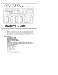
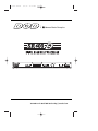
SR 400D manual
6/8/99
10:54 AM
Page 1
S
Harman Music Group Inc.
Visit DOD on the World Wide Web at http://www.dod.com
SR 400D manual
6/8/99
10:54 AM
Page 2
IMPORTANT!
FOR YOUR PROTECTION, PLEASE READ THE FOLLOWING:
WATER AND MOISTURE: Appliance should not be used near water (e.g. near a bathtub, washbowl, kitchen sink, laundry tub, in a wet basement, or near a swimming pool, etc). Care should be taken so that objects do not fall on and liquids are not spilled into the enclosure through
openings.
POWER SOURCES: The appliance should be connected to a power supply only of the type described in the operating instructions or as
marked on the appliance.
GROUNDING OR POLARIZATION: Precautions should be taken so that the grounding or polarization means of an appliance is not defeated.
POWER CORD PROTECTION: Power supply cords should be routed so that they are not likely to be walked on or pinched by items placed
upon or against them, paying particular attention to cords at plugs, convenience receptacles, and the point where they exit from the appliance.
SERVICING: The user should not attempt to service the appliance beyond that described in the operating instructions. All other servicing
should be referred to qualified service personnel.
FUSING: If your unit is equipped with a fuse receptacle, replace with only same type fuse. Refer to replacement text on the unit for correct
fuse type.
Warranty
1. The warranty registration card must be mailed within ten days after purchase date to validate this warranty.
2. DOD warrants this product, when used solely within the U.S., to be free from defects in materials and workmanship
under normal use and service.
3. DOD liability under this warranty is limited to repairing or replacing defective materials that show evidence of defect, provided the product is returned to DOD WITH RETURN AUTHORIZATION, where all parts and labor will be covered up to
a period of two (2) years. A Return Authorization number may be obtained from DOD by telephone. The company shall
not be liable for any consequential damage as a result of the product’s use in any circuit or assembly.
4. Proof-of-purchase is considered to be the burden of the consumer.
5. DOD reserves the right to make changes in design or make additions to or improvements upon this product without
incurring any obligation to install the same on products previously manufactured.
6. The foregoing is in lieu of all other warranties, expressed or implied, and DOD neither assumes nor authorizes any person to assume for it any obligation or liability in connection with the sale of this product. In no event shall DOD or its
dealers be liable for special or consequential damages or from any delay in the performance of this warranty due to causes beyond their control.
DOD® and SR 400 D™ are registered trademarks of DOD Electronics Corporation.
The information contained in this manual is subject to change at any time without notification. Some information contained
in this manual may also be inaccurate due to undocumented changes in the product or operating system since this version of
the manual was completed. The information contained in this version of the owner's manual supersedes all previous versions.
SR 400D manual
6/8/99
10:54 AM
Page 1
Signal Processing
Table of Contents
Warranty ..........................................................................................................................................................iv
Introduction ....................................................................................................................................................2
Safety Precautions ............................................................................................................................................2
SECTION 1 - GETTING STARTED ................................................................................................................3
Supplying Power ..............................................................................................................................................3
Front Panel Controls ....................................................................................................................................3
Bypass Button ..................................................................................................................................................3
Mode Button ....................................................................................................................................................3
Utility Button....................................................................................................................................................4
Display Window ..............................................................................................................................................4
Signal / Clip LEDs ............................................................................................................................................4
Level Button ....................................................................................................................................................4
Store Button ....................................................................................................................................................4
Delay 1 ............................................................................................................................................................4
Delay 2 ............................................................................................................................................................4
Data Wheel ......................................................................................................................................................4
Channel 1 Knob ..............................................................................................................................................4
Channel 2 Knob ..............................................................................................................................................4
Rear Panel Connections................................................................................................................................4
Channel 1 / XLR Input ....................................................................................................................................4
Barrier Strip Input Connection ......................................................................................................................4
Channel 2 XLR Input ......................................................................................................................................5
Channel 1 XLR Output ....................................................................................................................................5
Barrier Strip Output Connection ....................................................................................................................5
Channel 2 XLR Output ....................................................................................................................................5
Power Adapter Input........................................................................................................................................5
SECTION 2 - PROGRAMMING SR 400 D ....................................................................................................5
Selecting and Editing Delays............................................................................................................................5
Temperature ....................................................................................................................................................5
Humidity ..........................................................................................................................................................5
Storing Programs..............................................................................................................................................5
Mode ................................................................................................................................................................6
Bypassing the SR 400 D's Programs ................................................................................................................6
SECTION 3- THE UTILITY MENU ................................................................................................................6
Key Lock ..........................................................................................................................................................6
Temperature Unit Selection ............................................................................................................................6
LCD Contrast....................................................................................................................................................6
Humidity ..........................................................................................................................................................6
Temperature ....................................................................................................................................................7
Factory Reset ....................................................................................................................................................7
Specifications ..................................................................................................................................................7
1
SR 400D manual
6/8/99
10:54 AM
Page 2
Signal
SignalProcessing
Processing
INTRODUCTION
Congratulations and thank you for your purchase of the DOD SR 400 D room delay
processor. With the SR 400 D room delay, dialing-in the unique sounds and characteristics of each venue is a breeze. The SR 400 D lets you enter in information such
as Delay time, Room temperature and humidity and then it takes care of all of the
calculations for optimizing the sound of the room. The SR 400 D provides you with
single or dual input and output configurations, with two independent, programmable
delays. The SR 400 D also comes equipped with XLR and Barrier strip Inputs and Outputs
as standard features.
Safety Precautions
Do not open the unit. Do not attempt to service the unit yourself. Refer
all servicing to qualified personnel. Opening the chassis for any reason
will void the manufacturer's warranty. Do not get the unit wet. If liquid is
spilled on the unit, shut it off immediately and take it to a dealer for
service. Disconnect the equipment during storms to prevent damage.
2
SR 400D manual
6/8/99
10:54 AM
Page 3
Signal
SignalProcessing
Processing
SECTION 1 - GETTING STARTED
Supplying Power
The SR 400 D, like any piece of computer hardware, is sensitive to voltage drops,
spikes and surges. Interference such as lightning or power "brownouts" can seriously,
and in extreme cases, permanently damage the circuitry inside the unit. Here are a
few tips that will help you get the best possible performance out of your SR 400 D
while avoiding damage:
• Always make sure you have a "clean" power source for connecting to
the SR 400 D. This means that the AC power line you connect to the SR
400 D should be as free from voltage fluctuations and RF interference as
possible. In recording environments, "clean" power is also important in
preventing AC hum or buzz from getting to tape.
• Use a good quality spike / surge suppressor (also called a power strip).
This is an inexpensive solution to all but the most severe AC line
conditions. A good quality power strip can save you a lot of money in
repair bills because they prevent large spikes and surges from reaching
your equipment racks. Also in this category (but more expensive) are
rack mount power supplies. Some of these (such as the DOD 828), have
retractable light tubes and RF filtering.
• AC line conditioners offer the best protection from improper line voltages.
Line conditioners constantly monitor the AC line for excessively high or low voltages
and instantaneously compensate to deliver a consistent voltage to the connected
equipment.
• Always make sure that your audio lines are as far as possible from
power cables. This will further prevent noise, hum, and stray
magnetic fields from entering your signal path. If audio and power
lines must run close to each other, try to avoid running them parallel
to one another.
Front Panel Controls
1
2
3
4
5
6
7
8
9
10
11
The front panel of the SR 400 D is laid out in a simple and straight forward way to
make programming as easy as possible. Functions of each section are:
1) BYPASS - This button puts the SR 400 D into Bypass mode. This button also
scrolls the display screen to the left when the SR 400 is in utility mode
2) MODE - This button lets you select the INPUT and OUTPUT modes of the SR
400 D. The selections are: 1 IN and 2 Out or 2 IN and 2 Out. This button also scrolls
3
SR 400D manual
6/8/99
10:54 AM
Page 4
Signal
SignalProcessing
Processing
the display to the right when the SR 400 D is in utility mode.
3) UTILITY - This button is used to put the SR 400 D in Utility mode. Once in utility mode, the SR 400 lets you edit functions such as: Temperature, Humidity, delay
units, humidity units, Screen contrast and Keyboard lock.
4) DISPLAY - The display of the SR 400 D shows all pertinent programming informa-tion of the SR 400 D.
5) CLIP and Signal LEDs - The green signal LED indicates signal is being sent into
the SR 400 D. The red clip LED indicates the input signal is clipping the unit internally. If the Clip LED is lighting, turn the input level down until clipping stops.
6) STORE - Press the store button to save any changes made to the unit. To exit the
store mode, simply press any one of the other buttons to exit.
7) DELAY 1 - This button is used to select Delay 1 for editing the delay unit.
8) DELAY 2 - This button is used to select Delay 2 for editing the delay unit.
9) DATA WHEEL - The Data Wheel is used to make edits to any of the selected
functions.
10) INPUT KNOB CHANNEL 1 - Controls the level of the signal at the SR 400 D's Channel 1 input
level. Set this level until the CLIP LED begins to light and back off the knob slightly. When the
INPUT knob is set properly, the CLIP LED should flicker dimly on only the loudest
passages.
11) INPUT KNOB CHANNEL 2 - Use this knob to control the input level of Channel 2.
Rear Panel Connections
1
2
3
4
5
6
7
The SR 400 D's rear panel is even simpler than the front, and that means faster hookup
times for you. The rear panel has:
1) CHANNEL 1 XLR INPUT- This is the connection for the Channel 1 input of the SR 400 D. For single input applications, use this input.
2) BARRIER STRIP INPUT CONNECTION - This is the Barrier strip connection for the Channel 1 and 2 Inputs
connections of the SR 400D.
4
SR 400D manual
6/8/99
10:54 AM
Page 5
Signal
SignalProcessing
Processing
3) CHANNEL 2 XLR INPUT - This is the Channel 2 INPUT XLR connector
4) CHANNEL 1 XLR OUTPUT- This is the Channel 1 XLR Output connector.
5) BARRIER STRIP OUTPUT CONNECTION- This is the Barrier strip connection for the Channel 1 and 2 outputs of
the SR 400 D.
6) CHANNEL 2 XLR OUTPUT - This is the Channel 2 Output XLR connector.
7) AC INPUT - Connect the included DOD PS 750 power supply here.
SECTION 2 - PROGRAMMING THE SR 400 D
Selecting and Editing Delays
The SR 400 D is designed to be both easy to program and flexible. The structure of
a SR 400 D is logical, and does not require a lot of time to master.
1) After you power up, Select which delay you wish to edit. Press either <Delay 1>
or <Delay 2> buttons.
2) Now use the <Data Wheel> to change the Delay times. The Delays can be set to
be read as the following with the minimum and maximum values accordingly:
Delay Milliseconds Delay Meters Delay Feet -
Min.= 00.0ms
Min.= 00.0m
Min.= 00.0 f
Max.= 2000.00ms
Max.= 697.651m
Max.= 2288.88f
Note: The Maximum Delay in Feet and Meters will vary depending on the Temperature and Humidity settings.
These Delay units can be changed in the utility menu.
Once the satisfactory delay unit has been entered, simply press the <Store> button
to save changes.
Temperature
Since temperature plays such a big part of in acoustics of room delay, the SR 400 D
lets you change enter in the temperature of the room, then the SR 400D will do the
calculating to change the delay time. This change will cause the Audio signal to arrive at its Point of
sound destination at the correct time.
Humidity
Humidity also plays a factor in the fluctuation of Room Delay times. The SR 400 D allows you to change the
Humidity percentage (this is performed in the utilities menu), so the sound reaches its Audio destination at the correct time.
Storing Delay Presets
Once all of the elements are in place and Delay settings are correct, simply press the store button and all changes
will be saved.
5
SR 400D manual
6/8/99
10:54 AM
Page 6
Signal
SignalProcessing
Processing
Mode Selection
The Mode selection of the SR 400 D allows you to choose between a 1-In and 2-Out or a 2-In and 2-Out configuration. To select either of the two modes, press the <Mode> button and use the <Data Wheel> to change the configuration mode. Once selected, press the <Store> button.
To exit the Mode function, press the <Mode> button again.
Bypass Selection
By pressing the <Bypass> button on the front panel of the SR 400 D, this places the unit in Bypass mode.
The unit will continue to pass signal.
SECTION 3- UTILITY MENU FUNCTIONS
The Utility menu within the SR 400 D offers the User countless functions to help in
programming and using the unit to its fullest potential.
The following pages give performance function notes for the all of the sub-menus of
the SR 400 D.
Key Lock Out
This unique function of the SR 400 D lets you lock-in your Delay settings and keep them that way.
To set the Key Lock, first press the <Utility> button and use the <Mode> button to scroll to
the right. Once you are at the Key lock function, turn the <Data Wheel> clockwise until the word: Locked
appears in the screen. Now a lock icon will appear in the display, indicating that the Delays are locked in place.
To unlock, press and hold the <Delay 2> button for approximately 5 seconds.
Temperature Unit Selection
The SR 400 D can display temperature in either Fahrenheit or Celsius Degrees. To select either one , press the
<Utility> button and use the <Mode> button to scroll to right until Temp Units appears in the display. Now use the
<Data Wheel> to select the measuring unit to be used.
LCD Contrast
To change the viewing display contrast of the SR 400 D, enter the Utility mode and use the <Mode> button to scroll
to the LCD contrast. Now turn the <Data Wheel> to change the display contrast. Once the contrast has been set,
press the <Utility> button to exit.
Humidity
When Humidity in a room changes, it can effect Room delay. To change the percentage of humidity so the SR 400 D
will calculate the correct delay, press the <Utility> button and use either the <Bypass> or <Mode> buttons to
scroll to the Humidity setting. Once there, the setting of Humidity can be changed. Range is 0 to 100% by using the
<Data Wheel>.
Note: This utility function can only be used when the Delay Unit is being measured in Feet or Meters.
6
SR 400D manual
6/8/99
10:54 AM
Page 7
Signal
SignalProcessing
Processing
Temperature
The temperature of a venue also plays a crucial role in affecting the Room delay. The SR 400 D allows you to enter in
the current room temperature. Once the correct temperature is entered, the SR 400 D will re-calculate the Room
delay so the correct delay is used.
The procedure for changing the Temperature of the SR 400 is as follows:
From performance mode, press the <Utility> button and use the <Bypass> and <Mode> button to scroll to the
Temperature setting. Now depending on the Temperature Unit Selection (Page 6), the the temperature will either
read in Celsius (0 to 30 degrees)or Fahrenheit (32 to 86 degrees). Now use the <Data Wheel> to select the
desired temperature. Once selected, the SR 400 D will re-calculate and the correct Delay is heard.
Note: This utility function can only be used when the Delay Unit is being measured in Feet or Meters.
Factory Reset
To Factory reset the SR 400 D to its original default settings, you must perform the following procedure.
Press and hold the <Bypass> button while supplying power to the unit. The display reads: Reset SR 400D? Now
release the <Bypass> button and press the <Delay 2> button. The SR 400 D will now be returned to its original
default settings.
Specifications
A/D/A Resolution: 18/16 bit
Frequency Response: 20 - 16 kHz
THD: .08%
Signal-To-Noise Ratio: 90dB (typical)
Input Impedance: 40 kΩ balanced
Output Impedance: 100Ω balanced
Weight: 3.3 Lbs - 1.5 Kg
Dimensions:
1.75” X 4.75” X 19”
Power Supply: 9 VAC @ 750 mA
7
SR 400D manual
6/8/99
10:54 AM
Page 8
DECLARATION OF CONFORMITY
Manufacturer’s Name:
DOD Electronics
Manufacturer’s Address:
8760 S. Sandy Parkway
Sandy, Utah 84070, USA
declares that the product
Product Name:
SR 400 D
Product Options:
All (with a Class II power adapter that conforms to the requirements of
EN60065, EN60742, or equivalent).
conforms to the following product specifications:
Safety:
EN 60065 (1993)
IEC63 (1985) with Amendments 1,2,3
EMC:
EN 55013: (1990)
EN 55020: (1991)
Supplementary Information:
The product herewith complies with the requirements of the Low Voltage Directive 73/23/EEC and the
EMC Directive 89/336/EEC as amended by directive 93/68/EEC.
DOD Electronics
President of DOD
8760 S. Sandy Parkway
Sandy, Utah 84070, USA
Effective:
April 5th, 1997
DOD Electronics Corporation
8760 South Sandy Parkway
Sandy, Utah, 84070
Telephone (801) 566-8800
FAX (801) 566-7005
International Distribution: 3 Overlook Drive, Unit 4
Amherst, New Hampshire 03031 U.S.A.
FAX (603) 672-4246
SR 400 D is a registered trademark of DOD Electronics Corporation
Copyright © 1997
DOD Electronics Corporation
Printed In U.S.A. 3/97
Manufactured in the U.S.A.
SR 400 D 18-2203-A
OS V1.0