1
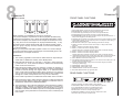
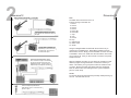
O WNER'S M ANUAL
DOD Electronics Corporation
8760 South Sandy Parkway
Sandy, Utah 84070
Dimension12
International Distribution
3 Overlook Drive Unit 4
Amherst, New Hampshire 03031
U.S.A.
FAX (603) 672-4246
DOD is a Registered Trademark of DOD
Electronics
© 1998 DOD Electronics Corporation
Printed In U.S.A. 3/98
DOD 18-2230-A
D O D E L E C T R O N I C S C O R P O R AT I O N
WARNING
CAUTION
FOR YOUR PROTECTION, PLEASE READ THE FOLLOWING:
RISK OF ELECTRIC SHOCK
DO NOT OPEN
A T T E N T I O N : RISQUE DE CHOC ELECTRIQUE - NE PAS OUVRIR
W A R N I N G : TO REDUCE THE RISK OF FIRE OR ELECTRIC
SHOCK DO NOT EXPOSE THIS EQUIPMENT TO RAIN OR MOISTURE
These symbols are internationally accepted symbols that warn of potential hazards with electrical products. The lightning flash means that there are dangerous voltages present within the unit. The exclamation point indicates that it is
necessary for the user to refer to the owner’s manual.
These symbols warn that there are no user serviceable parts inside the unit.
Do not open the unit. Do not attempt to service the unit yourself. Refer all servicing to qualified personnel. Opening the chassis for any reason will void the
manufacturer’s warranty. Do not get the unit wet. If liquid is spilled on the unit,
shut it off immediately and take it to a dealer for service. Disconnect the unit
during storms to prevent damage.
WATER AND MOISTURE: Appliance should not be used near water (e.g. near a
bathtub, washbowl, kitchen sink, laundry tub, in a wet basement, or near a swimming
pool, etc). Care should be taken so that objects do not fall and liquids are not spilled
into the enclosure through openings.
POWER SOURCES: The appliance should be connected to a power supply only of
the type described in the operating instructions or as marked on the appliance.
GROUNDING OR POLARIZATION: Precautions should be taken so that the grounding or polarization means of an appliance is not defeated.
POWER CORD PROTECTION: Power supply cords should be routed so that they are
not likely to be walked on or pinched by items placed upon or against them, paying
particular attention to cords at plugs, convenience receptacles, and the point where
they exit from the appliance.
DECLARATION OF CONFORMITY
Manufacturer’s Name:
DOD Electronics Corporation
Manufacturer’s Address:
8760 S. Sandy Parkway
Sandy, Utah 84070, USA
declares that the products:
SERVICING: To reduce the risk of fire or electric shock, the user should not attempt
to service the appliance beyond that described in the operating instructions. All other
servicing should be referred to qualified service personnel.
Product Name:
Dimension12
FOR UNITS EQUIPPED WITH EXTERNALLY ACCESSIBLE FUSE RECEPTACLE:
Replace fuse with same type and rating only.
Product Options:
All
conform to the following product specifications:
U.K. MAINS PLUG WARNING
ELECTROMAGNETIC COMPATIBILITY
A moulded mains plug that has been cut off from the cord is unsafe. Discard the
mains plug at a suitable disposal facility. NEVER UNDER ANY CIRCUMSTANCES SHOULD YOU INSERT A DAMAGED OR CUT MAINS PLUG INTO
A 13 AMP POWER SOCKET. Do not use the mains plug without the fuse cover
in place. Replacement fuse covers can be obtained from your local retailer.
Replacement fuses are 13 amps and MUST be ASTA approved to BS1362.
SAFETY INSTRUCTIONS
WARNING: THIS APPLIANCE MUST BE EARTHED.
The cores in the mains lead are coloured in accordance with the following code:
BLUE - Neutral
EN 60065 (1993)
IEC63 (1985) with Amendments 1,2,3
EMC:
EN 55013 (1990)
EN 55020 (1991)
The products herewith comply with the requirements
of the Low Voltage Directive 73/23/EEC and the EMC
Directive 89/336/EEC as ammended by directive
93/68/EEC.
BROWN - Live
As colours of the cores in the mains lead of this appliance may not correspond
with the coloured markings identifying the terminals in your plug, proceed as follows:
• The core which is coloured green and yellow must be connected to the
terminal in the plug marked with the letter E, or with the earth symbol, or
coloured green, or green and yellow.
• The core which is coloured blue must be connected to the terminal
marked N or coloured black.
• The core which is coloured brown must be connected to the terminal
marked L or coloured red.
This equipment may require the use of a different line cord, attachment plug, or
both, depending on the available power source at installation. If the attachment
plug needs to be changed, refer servicing to qualified service personnel who
should refer to the table below. The green/yellow wire shall be connected
directly to the unit's chassis.
CONDUCTOR
Safety:
Supplementary Information:
NOTICE FOR CUSTOMERS IF YOUR UNIT IS EQUIPPED WITH A POWER
CORD.
GREEN and YELLOW - Earth
Operation is subject to the following conditions:
• this device may not cause harmful interference, and
• this device must accept any interference received, including interference
that may cause undesired operation.
• use only shielded interconnecting cables.
• operation of this unit within significant electromagnetic fields should be
avoided.
WIRE COLOR
L
Line
Brown
Black
N
Neutral
Blue
White
Earth Grnd.
Green/Yel.
Green
WARNING: If the ground is defeated, certain fault conditions in the unit or in the
system to which it is connected can result in full line voltage between chassis
and earth ground. Severe injury or death can then result if the chassis and
earth ground are touched simultaneously.
DOD Electronics Corporation
President of DOD
8760 S. Sandy Parkway
Sandy, Utah 84070, USA
Effective: 11/24/98
European Contact: Your Local DOD Sales and Service Office or
International Sales Office
3 Overlook Drive #4
Amherst, New Hampshire 03031, USA
Tel (603) 672-4244
Fax (603) 672-4246
8
1
Dimension12
Dimension12
SAMPLE BANKS
FRONT PANEL FUNCTIONS
1
When sampling, the capabilities of the D12 are as follows:
4 six second samples, only bank1&2 or 3&4 are playable simultaneously.
2 twelve second samples, only 1 twelve second sample playable at a time.
2 six second samples, and 1 twelve second sample can be stored in memory. Only the 2 six second samples can be played simultaneously. It may
be easier to think of bank 1&2 and bank 3&4 as seperate sample groups.
Only one “group” can play at a time, whether it is 2 six second samples, or
1 12 second sample.
NOTE you must press both banks together to select a 12 second sample.
If you have selected a twelve second sample, and accidentally press a single bank button, the sample will be lost.
1.
2.
3.
4.
5.
6.
7.
8.
9.
10.
11.
12.
13.
WARRANTY
14.
1. The warranty registration card must be mailed within ten days after purchase date to validate the warranty of this DOD product.
15.
16.
2. DOD warrants this product (1 year parts, 1 year labor ), when used solely within the U.S., to be free from defects in material and workmanship
under normal use and service.
17.
3. DOD Electronics liability under this warranty is limited to repairing or
replacing defective materials that show evidence of defect, provided the
product is returned through the original dealer, or an authorized DOD
sevice center where all parts and labor will be covered up to a period of
one (1) year. The company shall not be responsible for any consequential
damage as a result of the products use in any circuit or assembly.
18.
19.
20.
21.
2
3
4
5
6
7
8
9
10
11
12
13
14
15 16
17
18
19
20
21
INPUT LEVEL KNOB controls the amount of signal that enters the D12
RECORD BUTTON engages the record function of the D12
PLAY BUTTON plays the sample in the D12’s currently selected bank
STOP BUTTON stops the sample in the D12’s currently selected bank
GATE/REVERSE activates the gate or enables sample to be played backwards. In
delay mode it engages reverse delay function.
STUTTER places a marker in the sample to return to every time the button is pushed
DATA WHEEL enables you to find specific points in the sample for easier editing. In
delay mode it selects delay time.
EDIT BUTTON enables you to place start/stop points within the sample
DISPLAY shows a numeric time index of the sample. In delay mode it shows
delay time
BANK 1 accesses 6 seconds of sampling in bank 1
BANK 2 accesses 6 seconds of sampling in bank 2
Selecting both bank 1 and bank 2 accesses 12 seconds of combined sampling
BANK 3 accesses 6 seconds of sampling in bank 3
BANK 4 accesses 6 seconds of sampling in bank 4
Selecting both bank 3 and bank 4 accesses 12 seconds of combined sampling
LOOP BUTTON Enables sample to start playing again when it reaches its end point.
When engaged the sample will play continuously until button is pressed again.
DELAY BUTTON Places D12 in delay mode
TAP TEMPO BUTTON Tapping this button in time with the music enables you to set
the delay time in time with the music.
EFFECT ON/OFF BUTTON Engages the LFO for effects ranging from subtle
chorusing to jetlike flanging.
SPEED KNOB Controls speed of LFO
DEPTH KNOB Controls depth of LFO
FEEDBACK KNOB Controls amount of feedback
MIX KNOB Blends between dry signal and effect
REAR PANEL FUNCTIONS
4. Proof of date of purchase is considered to be the burden of the consumer.
5. DOD reserves the right to make changes in design or make improvements
upon this product without incurring any obligation to install the same on
PRODUCTS PREVIOUSLY MANUFACTURED.
6. The foregoing is in lieu of all other warranties, either expressed or implied,
and DOD neither assumes nor authorizes any person to assume any
obligation or liability in connection with the sale of this product. In no event
shall DOD or its dealers be liable for special or consequential damages or
from any delay in the performance of this warranty due to causes beyond
their control.
1
1.
2.
3.
4.
5.
6.
7.
2
3
4
5
MIDI IN JACK Plug your MIDI controller in here (optional)
FOOTSWITCH INPUT Connect in the DOD FS3M here (optional)
A.C. ADAPTER INPUT Connect in the DOD PS750 in here
MONITOR OUTPUT Connect to mixer/pre-amp/amp input.
MAIN OUTPUT Connect to mixer/pre-amp/amp input.
MAIN INPUT (STEREO) Connect output from sample source here
MIC INPUT (HI-Z) Connect microphone here
6
7
2
Dimension12
7
Dimension12
ROUTING/INSTALLATION
Connect guitar out directly to the D12’s
input, connect main output to the amplifiers input.
Connect guitar out directly to the
amplifier input, connect fx send to
the D12’s input, and fx return to
the D12’s main output.
Connect fx send to D12’s input, and fx
return to the D12’s output. This will allow
any signal connected to the mixer to be
sampled by the D12. Connect monitor to
seperate input for headphone monitoring.
MIDI
The MIDI recieve channel is set to 10.
Program change commands are:
1. bank 1
2. bank 2
3. bank 3
4. bank 4
5. bank 1&2
6. bank 3&4
7. stop
8. play
9. record
10. loop
11. gate/reverse
12. effect on/off
13. stutter
Using an intelligent MIDI controller with the D12 is the key to
unlocking its incredible power. Basic MIDI controllers will work
with the D12 as well. Simply connect the MIDI out of the controller
to the MIDI in of the D12. Make sure the Controller is set to transmit on channel 10. Now you have access to all of the front panel
sample functions.
With an intelligent controller you can assign the controller to send
different program change information on whichever switch you
desire. This allows you to group the functions in whatever order
you wish. Higher end guitar rack effects and some keyboards
allow for this function, thus making the D12 a great companion
piece to a rack setup.
RESET
To reset the D12 hold down both Play and Stop while powering up
the unit. This will reset the unit.
Connect microphone (with XLR-1/4”
cable) directly to D12. Connect D12 output to P.A. input.
6
Dimension12
EFFECT
The effects parameter controls consist of an FX on/off button (17),
a mix knob (21), an effects LFO speed control (18), a modulation
depth control (19), and an effects feedback control (20). Effects
may be used in both record and play back mode. The effect on/off
is linked individually with each memory bank. Chorusing can be
acheived with depth set to 1:00, feedback set to 9:00, and speed
set to 8:00, and mix of 50% Flanging is acheived by setting depth
to 3:00, feedback to 12:00, and speed to 10:00. For effects operation in delay mode make sure delay time is set to 0.
RECORDING WITH EFFECTS
Press the FX button and adjust the controls (speed, depth, feedback, mix) to the desired effect. Note, the dry signal can be heard
out of the main channel while in record mode, and the wet/dry mix
out of the monitor channel.
PLAYING WITH EFFECTS
The FX button can be pressed for, and is, independently linked to
each of the memory banks, however, the settings of the FX parameters (speed, depth, feedback and mix) are globally set with the
controls. Even if the sample was recorded with effects, the sample can be played back with effects, thereby increasing the modulation effect.
FOOTSWITCH - The optional 3 button foot switch (FS3M) controls the following functions: In sampling modes, switch 1 is stop,
and switch 3 is play. For the delay mode, switch 1 sample/hold,
switch 2 is tap tempo, and switch 3 is effect on/off. in reverse
mode only tap tempo is operational.
3
Dimension12
RECORD
Select bank 1, 2, 3, or 4 (6 seconds each) or 1&2 or 3&4 (12 seconds
each) Press record button (record LED will light indicating record is
active). Press stop when done or wait until the full record time has finished. (Monitor out plays dry signal only.)
GATED RECORD
Select bank. Press gate button. Press record. Record LED flashes
waiting for input signal. Gate threshold is -25dB.
PLAY
Select desired bank, and press Play Button (3). If no edit point is set,
play will start at the beginning of the sample. If an edit point is set then
play will begin at specified start point. (Monitor out will play selected
bank only.)
LOOPING
Press the desired bank, press the Loop Button (14), (LED will light indicating loop is active), press Play Button (3). The sample will play from
beginning to the end of the 6 or 12 second sampling time, depending
on which was selected. With looping on, the sound sample will then
continue to be repeated. If the start and stop points were changed
using the editing funtion, play will start from the new start point and end
with the new end point (see editing). Looping will continue to play
between the new start and stop points until the Stop Button (4) is
pressed.
REVERSE
The Gate/Reverse Button (5) will cause the sample to be played backwards. This function is used in play mode. To stop the reverse playback, press the Stop Button (4), and then press Gate/Reverse Button.
OVERLAYS
Two banks my be played back together, either bank 1 and 2 or 3 and
4. For example, this function my be accomplished by pressing bank 1
and the Play Button (3), and then pressing bank 2 and the Play Button
(3). Each bank can have its own set of above functions independently
associated with each bank, i.e., bank 1 for instance may be played in
reverse with effects, and its own separate stutter, while bank 2 can be
played forward with no effects and its own stutter point.
4
Dimension12
STUTTER
The Stutter Button (6) is used on the “fly”, that is while the sound
sample is being played, the Stutter Button (6) is pressed at the
point where you want the sample to “stutter”. When the Stutter
Button (6) is pressed the first time, the Stutter LED lights indicating
a stutter point has been selected. Subsequent presses of the
Stutter Button (6) will return the sound sample to the stutter point
and begin playing from that point. If the sound sample has played
to the end and stopped (play LED off) and a stutter point has been
set, pressing the Stutter Button (6) now will initiate play mode and
will start the sound sample playing from the stutter point. A stutter
point can be easily cleared, by depressing the active memory
bank(s) (the bank(s) with LEDs on), the stutter LED turns off (CAUTION: if two banks for 12 second mode have been selected, you
must ensure that you depress BOTH buttons to clear the stutter
point. If only one is accidently pressed, all contents of the memory
bank will also be cleared).
EDITING
Editing of the start and stop points is accomplished by pressing the
Edit Button (8). In this mode, all other buttons and functions are
locked out until both start and stop have been set (or the Edit
Button (8) has been pressed twice). To set the start point, press
the Edit Button (8) once (the green LED blinks). Set the start time
with the encoder wheel and press the Edit Button (8). Set the end
stop point time with the encoder and press the Edit Button (8)
again. Editing the start and stop time can also be done on the fly.
While the sound sample is playing, the Edit Button (8) may be
pressed at the desired start time (green LED lights), the red LED
then continues to flash indicating it is waiting for the stop time to be
set. Pressing the Edit Button (8) again will set the stop time. If it is
not pressed, the sample will continuing playing to the end of the
sampling time, and the end of the buffer will be the default stop
time. For on the fly editing, if any other buttons are pressed e.g.
FX button, the editing function is automatically exited
5
Dimension12
REVERSE MODE EDITING
On the fly editing of the sound sample will operate in play mode in
forward play only, no reverse mode editing is allowed.
DELAY MODE
This mode is accessed by pressing the Delay button (15). Turn
the Data Wheel (7) to select desired delay time (0 ms-12 seconds). Turn the Mix Knob (21) to 12:00 (50/50) and play. For “on
the fly” tempo adjustment, use the FS3M footswitch to control the
tap tempo externally. The D12 will remember the last delay setting
used upon powering up.
REVERSE DELAY
This mode is accessed by selecting delay mode (15), and then
selecting Gate/Reverse (5). This mode allows you to play a
phrase and have it played back backwards. Minimum delay time
is 20ms. Turn the Data wheel (7) to select the amount of time
you wish to be reversed, play a phrase, and when you reach the
end of the time selected, the phrase you just played will be repeated back to you in reverse. If you are using the rear panel Monitor
Output (4), you will hear the phrase as you play and then the
reverse. If you use the Main Output (5), you will hear only the
reversed signal. This is a feature designed to give the user optimal signal routing flexibility.
6
Dimension12
EFFECT
The effects parameter controls consist of an FX on/off button (17),
a mix knob (21), an effects LFO speed control (18), a modulation
depth control (19), and an effects feedback control (20). Effects
may be used in both record and play back mode. The effect on/off
is linked individually with each memory bank. Chorusing can be
acheived with depth set to 1:00, feedback set to 9:00, and speed
set to 8:00, and mix of 50% Flanging is acheived by setting depth
to 3:00, feedback to 12:00, and speed to 10:00. For effects operation in delay mode make sure delay time is set to 0.
RECORDING WITH EFFECTS
Press the FX button and adjust the controls (speed, depth, feedback, mix) to the desired effect. Note, the dry signal can be heard
out of the main channel while in record mode, and the wet/dry mix
out of the monitor channel.
PLAYING WITH EFFECTS
The FX button can be pressed for, and is, independently linked to
each of the memory banks, however, the settings of the FX parameters (speed, depth, feedback and mix) are globally set with the
controls. Even if the sample was recorded with effects, the sample can be played back with effects, thereby increasing the modulation effect.
FOOTSWITCH - The optional 3 button foot switch (FS3M) controls the following functions: In sampling modes, switch 1 is stop,
and switch 3 is play. For the delay mode, switch 1 sample/hold,
switch 2 is tap tempo, and switch 3 is effect on/off. in reverse
mode only tap tempo is operational.
3
Dimension12
RECORD
Select bank 1, 2, 3, or 4 (6 seconds each) or 1&2 or 3&4 (12 seconds
each) Press record button (record LED will light indicating record is
active). Press stop when done or wait until the full record time has finished. (Monitor out plays dry signal only.)
GATED RECORD
Select bank. Press gate button. Press record. Record LED flashes
waiting for input signal. Gate threshold is -25dB.
PLAY
Select desired bank, and press Play Button (3). If no edit point is set,
play will start at the beginning of the sample. If an edit point is set then
play will begin at specified start point. (Monitor out will play selected
bank only.)
LOOPING
Press the desired bank, press the Loop Button (14), (LED will light indicating loop is active), press Play Button (3). The sample will play from
beginning to the end of the 6 or 12 second sampling time, depending
on which was selected. With looping on, the sound sample will then
continue to be repeated. If the start and stop points were changed
using the editing funtion, play will start from the new start point and end
with the new end point (see editing). Looping will continue to play
between the new start and stop points until the Stop Button (4) is
pressed.
REVERSE
The Gate/Reverse Button (5) will cause the sample to be played backwards. This function is used in play mode. To stop the reverse playback, press the Stop Button (4), and then press Gate/Reverse Button.
OVERLAYS
Two banks my be played back together, either bank 1 and 2 or 3 and
4. For example, this function my be accomplished by pressing bank 1
and the Play Button (3), and then pressing bank 2 and the Play Button
(3). Each bank can have its own set of above functions independently
associated with each bank, i.e., bank 1 for instance may be played in
reverse with effects, and its own separate stutter, while bank 2 can be
played forward with no effects and its own stutter point.
2
Dimension12
7
Dimension12
ROUTING/INSTALLATION
Connect guitar out directly to the D12’s
input, connect main output to the amplifiers input.
Connect guitar out directly to the
amplifier input, connect fx send to
the D12’s input, and fx return to
the D12’s main output.
Connect fx send to D12’s input, and fx
return to the D12’s output. This will allow
any signal connected to the mixer to be
sampled by the D12. Connect monitor to
seperate input for headphone monitoring.
MIDI
The MIDI recieve channel is set to 10.
Program change commands are:
1. bank 1
2. bank 2
3. bank 3
4. bank 4
5. bank 1&2
6. bank 3&4
7. stop
8. play
9. record
10. loop
11. gate/reverse
12. effect on/off
13. stutter
Using an intelligent MIDI controller with the D12 is the key to
unlocking its incredible power. Basic MIDI controllers will work
with the D12 as well. Simply connect the MIDI out of the controller
to the MIDI in of the D12. Make sure the Controller is set to transmit on channel 10. Now you have access to all of the front panel
sample functions.
With an intelligent controller you can assign the controller to send
different program change information on whichever switch you
desire. This allows you to group the functions in whatever order
you wish. Higher end guitar rack effects and some keyboards
allow for this function, thus making the D12 a great companion
piece to a rack setup.
RESET
To reset the D12 hold down both Play and Stop while powering up
the unit. This will reset the unit.
Connect microphone (with XLR-1/4”
cable) directly to D12. Connect D12 output to P.A. input.
8
1
Dimension12
Dimension12
SAMPLE BANKS
FRONT PANEL FUNCTIONS
1
When sampling, the capabilities of the D12 are as follows:
4 six second samples, only bank1&2 or 3&4 are playable simultaneously.
2 twelve second samples, only 1 twelve second sample playable at a time.
2 six second samples, and 1 twelve second sample can be stored in memory. Only the 2 six second samples can be played simultaneously. It may
be easier to think of bank 1&2 and bank 3&4 as seperate sample groups.
Only one “group” can play at a time, whether it is 2 six second samples, or
1 12 second sample.
NOTE you must press both banks together to select a 12 second sample.
If you have selected a twelve second sample, and accidentally press a single bank button, the sample will be lost.
1.
2.
3.
4.
5.
6.
7.
8.
9.
10.
11.
12.
13.
WARRANTY
14.
1. The warranty registration card must be mailed within ten days after purchase date to validate the warranty of this DOD product.
15.
16.
2. DOD warrants this product (1 year parts, 1 year labor ), when used solely within the U.S., to be free from defects in material and workmanship
under normal use and service.
17.
3. DOD Electronics liability under this warranty is limited to repairing or
replacing defective materials that show evidence of defect, provided the
product is returned through the original dealer, or an authorized DOD
sevice center where all parts and labor will be covered up to a period of
one (1) year. The company shall not be responsible for any consequential
damage as a result of the products use in any circuit or assembly.
18.
19.
20.
21.
2
3
4
5
6
7
8
9
10
11
12
13
14
15 16
17
18
19
20
21
INPUT LEVEL KNOB controls the amount of signal that enters the D12
RECORD BUTTON engages the record function of the D12
PLAY BUTTON plays the sample in the D12’s currently selected bank
STOP BUTTON stops the sample in the D12’s currently selected bank
GATE/REVERSE activates the gate or enables sample to be played backwards. In
delay mode it engages reverse delay function.
STUTTER places a marker in the sample to return to every time the button is pushed
DATA WHEEL enables you to find specific points in the sample for easier editing. In
delay mode it selects delay time.
EDIT BUTTON enables you to place start/stop points within the sample
DISPLAY shows a numeric time index of the sample. In delay mode it shows
delay time
BANK 1 accesses 6 seconds of sampling in bank 1
BANK 2 accesses 6 seconds of sampling in bank 2
Selecting both bank 1 and bank 2 accesses 12 seconds of combined sampling
BANK 3 accesses 6 seconds of sampling in bank 3
BANK 4 accesses 6 seconds of sampling in bank 4
Selecting both bank 3 and bank 4 accesses 12 seconds of combined sampling
LOOP BUTTON Enables sample to start playing again when it reaches its end point.
When engaged the sample will play continuously until button is pressed again.
DELAY BUTTON Places D12 in delay mode
TAP TEMPO BUTTON Tapping this button in time with the music enables you to set
the delay time in time with the music.
EFFECT ON/OFF BUTTON Engages the LFO for effects ranging from subtle
chorusing to jetlike flanging.
SPEED KNOB Controls speed of LFO
DEPTH KNOB Controls depth of LFO
FEEDBACK KNOB Controls amount of feedback
MIX KNOB Blends between dry signal and effect
REAR PANEL FUNCTIONS
4. Proof of date of purchase is considered to be the burden of the consumer.
5. DOD reserves the right to make changes in design or make improvements
upon this product without incurring any obligation to install the same on
PRODUCTS PREVIOUSLY MANUFACTURED.
6. The foregoing is in lieu of all other warranties, either expressed or implied,
and DOD neither assumes nor authorizes any person to assume any
obligation or liability in connection with the sale of this product. In no event
shall DOD or its dealers be liable for special or consequential damages or
from any delay in the performance of this warranty due to causes beyond
their control.
1
1.
2.
3.
4.
5.
6.
7.
2
3
4
5
MIDI IN JACK Plug your MIDI controller in here (optional)
FOOTSWITCH INPUT Connect in the DOD FS3M here (optional)
A.C. ADAPTER INPUT Connect in the DOD PS750 in here
MONITOR OUTPUT Connect to mixer/pre-amp/amp input.
MAIN OUTPUT Connect to mixer/pre-amp/amp input.
MAIN INPUT (STEREO) Connect output from sample source here
MIC INPUT (HI-Z) Connect microphone here
6
7
O WNER'S M ANUAL
DOD Electronics Corporation
8760 South Sandy Parkway
Sandy, Utah 84070
Dimension12
International Distribution
3 Overlook Drive Unit 4
Amherst, New Hampshire 03031
U.S.A.
FAX (603) 672-4246
DOD is a Registered Trademark of DOD
Electronics
© 1998 DOD Electronics Corporation
Printed In U.S.A. 3/98
DOD 18-2230-A
D O D E L E C T R O N I C S C O R P O R AT I O N