1
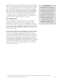
Agilent Technologies
ESG Family/RF Signal Generators
Product Note
ESG Signal Generator/Option 201
Real-time IS-2000 Mobile
Receiver Measurements
Table of contents
Introduction . . . . . . . . . . . . . . . . . . . . . . . . . . . . . . . . . . . . . . . . . . . . . . . . . . . . . . . . . . . . . . . . . . . . . . .3
IS-2000 measurement background . . . . . . . . . . . . . . . . . . . . . . . . . . . . . . . . . . . . . . . . . . . . . . . . . . . .4
ESG option 201 real-time CDMA2000 personality . . . . . . . . . . . . . . . . . . . . . . . . . . . . . . . . . . . . . . . .5
Overview . . . . . . . . . . . . . . . . . . . . . . . . . . . . . . . . . . . . . . . . . . . . . . . . . . . . . . . . . . . . . . . . . . . . . . . . .5
Key features . . . . . . . . . . . . . . . . . . . . . . . . . . . . . . . . . . . . . . . . . . . . . . . . . . . . . . . . . . . . . . . . . . . . . . .6
ESG option 201 IS-2000 real-time receiver test setup . . . . . . . . . . . . . . . . . . . . . . . . . . . . . . . . . . . .7
One-box setup . . . . . . . . . . . . . . . . . . . . . . . . . . . . . . . . . . . . . . . . . . . . . . . . . . . . . . . . . . . . . . . . . . . . .7
Two-box setup . . . . . . . . . . . . . . . . . . . . . . . . . . . . . . . . . . . . . . . . . . . . . . . . . . . . . . . . . . . . . . . . . . . . .1
Power mapping procedure . . . . . . . . . . . . . . . . . . . . . . . . . . . . . . . . . . . . . . . . . . . . . . . . . . . . . . . . . . .15
Real-time IS-2000 measuremnts . . . . . . . . . . . . . . . . . . . . . . . . . . . . . . . . . . . . . . . . . . . . . . . . . . . . . .17
Measurement overview . . . . . . . . . . . . . . . . . . . . . . . . . . . . . . . . . . . . . . . . . . . . . . . . . . . . . . . . . . . . . .17
Frame Error Rate (FER), Block Error Rate (BLER), and Bit Error Rate (BER) paramatic
measurements . . . . . . . . . . . . . . . . . . . . . . . . . . . . . . . . . . . . . . . . . . . . . . . . . . . . . . . . . . . . . . . . . . . . .17
FER measurement setup . . . . . . . . . . . . . . . . . . . . . . . . . . . . . . . . . . . . . . . . . . . . . . . . . . . . . . . . . .17
Sensitivity and dynamic range . . . . . . . . . . . . . . . . . . . . . . . . . . . . . . . . . . . . . . . . . . . . . . . . . . . . . .18
Adjacent channel interference . . . . . . . . . . . . . . . . . . . . . . . . . . . . . . . . . . . . . . . . . . . . . . . . . . . . . .18
Fading and multi-path distortions . . . . . . . . . . . . . . . . . . . . . . . . . . . . . . . . . . . . . . . . . . . . . . . . . . .18
Single tone desensitization . . . . . . . . . . . . . . . . . . . . . . . . . . . . . . . . . . . . . . . . . . . . . . . . . . . . . . . .18
Intermodulation spurious response attenuation . . . . . . . . . . . . . . . . . . . . . . . . . . . . . . . . . . . . . . . .19
Bit Error Rate (BER) tests . . . . . . . . . . . . . . . . . . . . . . . . . . . . . . . . . . . . . . . . . . . . . . . . . . . . . . . .19
Functional testing of algorithm decoding . . . . . . . . . . . . . . . . . . . . . . . . . . . . . . . . . . . . . . . . . . . . . . . .19
Messaging and protocol development, unidirectional . . . . . . . . . . . . . . . . . . . . . . . . . . . . . . . . . . . .19
Paging channel protocol development, unidirectional . . . . . . . . . . . . . . . . . . . . . . . . . . . . . . . . . . . .20
Flexible diagnostic tests for firmware . . . . . . . . . . . . . . . . . . . . . . . . . . . . . . . . . . . . . . . . . . . . . . . .20
Functional tests on single and multiple channels . . . . . . . . . . . . . . . . . . . . . . . . . . . . . . . . . . . . . . .20
Response to power control data . . . . . . . . . . . . . . . . . . . . . . . . . . . . . . . . . . . . . . . . . . . . . . . . . . . .20
Demonstration example . . . . . . . . . . . . . . . . . . . . . . . . . . . . . . . . . . . . . . . . . . . . . . . . . . . . . . . . . . .21
Appendix A – Specifications . . . . . . . . . . . . . . . . . . . . . . . . . . . . . . . . . . . . . . . . . . . . . . . . . . . . . . . .23
Appendix B – Terms and definitions . . . . . . . . . . . . . . . . . . . . . . . . . . . . . . . . . . . . . . . . . . . . . . . . . .24
Recommended reading . . . . . . . . . . . . . . . . . . . . . . . . . . . . . . . . . . . . . . . . . . . . . . . . . . . . . . . . . . . . .25
Related literature . . . . . . . . . . . . . . . . . . . . . . . . . . . . . . . . . . . . . . . . . . . . . . . . . . . . . . . . . . . . . . . . . .25
References . . . . . . . . . . . . . . . . . . . . . . . . . . . . . . . . . . . . . . . . . . . . . . . . . . . . . . . . . . . . . . . . . . . . . . .25
Ordering information . . . . . . . . . . . . . . . . . . . . . . . . . . . . . . . . . . . . . . . . . . . . . . . . . . . . . . . . . . . . . . .26
2
Introduction
The recent 1999 CDMA Americas Congress marked the milestone of
a decade of CDMA. Among the items highlighted were the exciting
opportunities for CDMA in the new millennium. With the evolution
toward 3G standards, CDMA is providing an even more exciting
opportunity. CDMA leads the industry in providing the highest quality
voice services and it is also leading the way in delivering wireless data
services. Used by nearly 42 million worldwide, CDMA is the predominant
global technology of choice for third generation (3G) services and
devices.1
Through its introduction of the ESG Option 201 real-time cdma20002
personality, Agilent Technologies is providing a significant advantage
in signal generation for customers developing mobile receivers for the
CDMA marketplace. The ESG Option 201 personality can be used to
provide fully coded, multi-channel stimulus signals supporting both the
IS-95 and IS-2000 (release 0) CDMA standards. These signals can be
used to test receiver performance (frame error rates) and low-level
protocol handling for CDMA products. Features include:
a) Fully coded IS-95 signal package including pilot, sync, paging, and
traffic channels.
b) Fully coded IS-2000 signals including fundamental and supplemental
channels at rates up to 307.2 kbps.
c) Full control of the paging message stream (overhead and signaling
messages).
This product note discusses features, setup, and applications for
Agilent Technologies’ ESG Option 201 Real-time cdma2000 personality.
It is intended to provide R&D designers working on DSPs, ASICs, and
other firmware components of IS-95 and IS-2000 mobile phones with
techniques for testing and troubleshooting their receiver designs. The
ESG Option 201 also provides designers with the ability to perform RF
design characterization, and will provide manufacturing engineers with
a suitable means of RF functional testing.
This product note assumes a working knowledge of CDMA and/or IS-2000.
For supplemental information on CDMA and receiver measurements,
please refer to the Recommended Reading section on page 25. Throughout the remainder of this document references are made to IS-2000;
unless otherwise noted, the reader may assume that these references
apply to IS-95 as well as IS-2000.
1.
2.
CDG (CDMA Development Group), www.cdg.org, CDMA Moves Into The New Millennium; Leading Wireless Companies Highlight CDMA Milestones and
Future at the CDMA Americas Congress, San Francisco, CA, November 30, 1999.
cdma2000, also referred to as the IS-2000 standard, refers to the 3rd generation migration of cdmaOne, which incorporates backward compatibility with
the IS-95 standard.
3
IS-2000 measurement background
Prior to the introduction of the ESG signal generator’s Option 201
real-time cdma2000 personality, testing of IS-2000 mobile receivers was
performed in a limited fashion using custom solutions or non real-time
solutions such as arbitrary waveform generators.
Custom solutions had their downsides. They required significant time
and effort to develop, they were typically complex and costly, and they
provided only limited functionality and flexibility.
Arbitrary waveform generator solutions, such as the ESG Option 101
multi-carrier, multi-channel cdma2000 personality, have been used in
the early stages of IS-2000 development to facilitate receiver design and
test. Beyond the typical stimulus-response requirements of component
test, arbitrary waveform generators also have the capability to simulate
much of the coding required to verify receiver designs. Arbitrary waveform generators have been used to provide the first level of support in
receiver test to ensure that receiver designs are demodulating and
despreading properly.
The Option 201 real-time cdma2000 personality goes beyond these
solutions by offering a second level of support to receiver design and
verification. The added benefits of fully coded channels with complete
long coding, the ability to utilize user-defined data, and the ability to
make real time changes provide additional capabilities to accelerate the
design process.
4
ESG Option 201 Real-time cdma2000 personality
The ESG’s Option 201 personality provides a complete solution for
testing of IS-2000 mobile receiver designs. This section provides an
overview of the Option 201 real-time IS-2000 system. It also describes
the Option 201 features.
Overview
The ESG with the Option 201 personality simulates a basestation transmitter to create a forward spread rate 1 (SR1) link for an IS-2000
mobile. The flexibility inherent in the ESG signal generator allows flexible channel configurations with individually adjustable power levels,
customized user data, and customizable data rates. Radio configurations
1-5 (RC1-RC5) are supported. An IS-2000 RC4 forward traffic link, as
supported by the personality, is shown below in Figure 1. Long and
short coding, cyclic redundancy checks, convolutional encoding or turbocoding, interleaving, power control, and complex scrambling are all
supported. Paging, Sync, and Pilot channels are similarly supported.
PRBS or
User-defined
Data
8.6 kbps
Add CRC and
Tail Bits
I
1/2 Rate Conv.
Encoder or
turbocoder
19.2 ksps
Interleaver
User Long
Code Mask
1.2288 Mcps
9.6 kbps
19.2
ksps
Power
Control
Puncture
P.C. Bits
800 bps
19.2 ksps
19.2
1.2288 ksps
Long Code Mbps Long Code
Generator
Decimator
Decimated by
Walsh Length/2
PC
Puncture 800 bps
Timing
PC
Dec
+
9.6 ksps
I Short Code
1.2288
Mcps
I
-
Σ
I
1.2288 Mcps
FIR
I
1.2288
Mbps
Walsh 128
Generator
S-P
Q
1.2288
Mbps
1.2288 Mcps
+
Q Short Code
9.6 ksps
Q
1.2288
Mcps
+
Σ
FIR
Q
Q
1.2288 Mcps
Figure 1. Forward coding path for an IS-2000 SR1 RC4 traffic channel
Because IS-2000 provides backward compatibility with IS-95 in RC1 and
RC2 configurations, the Option 201 personality also supports the IS-95
standard.
The menu structure of Option 201 shown in Figure 2 illustrates the
flexibility and features of the system. The BTS Setup menu, shown in
the bottom of the display, allows configuration of parameters common
to all channels, while the Link Control softkey provides a separate
configuration menu for individual channels.
Figure 2. Screen printout of CDMA2000 menu
5
Key Features
Key features of the Option 201 personality are highlighted in Table 1
below. The 1-BOX column refers to the IS-95 solution that utilizes one
ESG signal generator. The 2-BOX column refers to the IS-2000 solution
that utilizes two ESG signal generators; this allows more complex
signal structures as described in section in the two-box setup. Table 1
summarizes some differences between the one-box and two-box setups.
Table 1. Summary of key features
Description
• Fully coded IS-95 signal package including pilot,
sync, paging, and traffic channels
1-BOX
2-BOX
•
•
• Fully coded IS-2000 signals including fundamental and
supplemental channels at rates up to 307.2 kbps
• Full control of the paging message stream
(overhead and signaling messages)
• Supports both convolutional and turbo coding
• User data insertion via user files or external data
• Variable chip rates, 50 Hz to 1.3 MHz
• Fully configurable sync channel base station parameters
• Pilot, Sync, Paging, and RC1-RC2 Fundamental
(or OCNS) channels
• RC1-RC5 Fundamental and RC3-RC5 Supplemental channels
1.
2.
•
•
•1
•
•
•
•
•
•
•
•
•
•2
•
•
IS-95 modes do not support turbo coding.
One ESG can generate a group of channels including Pilot, Sync, Paging, and RC1-RC2 Fundamental or a group of channels including RC1-RC5 Fundamental
and RC3-RC5 Supplemental channels. A single ESG cannot generate both groups of channels simultaneously.
6
ESG Option 201 IS-2000
Real-time receiver test setup
The Option 201 personality provides significant flexibility in its configuration. It may be configured as a one-box IS-95 setup or as a two-box
IS-2000 setup. Since Option 201 is a real-time solution, it requires the
Option UN8 Real-time I/Q Baseband Generator for its operation.1 Below
are descriptions of a one-box setup and a two-box setup with configuration
examples.2
One-box setup
The one-box setup provides four IS-95 channels with real-time signal
generation capability. This setup may be used to test IS-95 receiver
designs. Figure 3 below provides the hardware configuration for the
one-box setup. Using an ESG signal generator with options UN8 and 201,
configure the hardware as shown in Figure 3. The one-box setup utilizes
internal I/Q triggering. EVENT 1 provides an even second clock with a
delay, which may be adjusted to align the frame timing with the RF output.
(Note: The delayed even second output provides a pulse every two
seconds and is used for synchronizing test equipment.) The 10 MHz
Out is used as a frequency reference for additional test equipment, if
needed.
Delayed
Even Second
Rear Panel
Q OUT I OUT EVENT 1
10 MHz OUT
ESG #1
(To DUT)
RF OUTPUT
Figure 3. One-box configuration for mobile receiver test
1.
2.
Option UN8, revision C or higher is required. Firmware revision B.03.40 or higher is also required.
The configuration examples described in this document assume a factory preset condition in the ESG.
7
After configuring the hardware, follow the steps in Table 2 below to configure the instrument appropriately. In this
example, Pilot, Sync, Traffic, and Paging channels are defined. For IS-95, the traffic channel may be defined as RC1
or RC2. This example is intended to illustrate a basic set-up from which the user can customize the instrument to
meet his needs. Values in brackets [ ] are for example purposes only and the actual value should be determined by
the user. Hard key selections are indicated by bold text.
Table 2. ESG instrument configuration for one-box setup
Parameter
Frequency
Amplitude
RF On/Off
Mode / (Real-time I/Q BaseBand)
CDMA
Phase Polarity
IQ Map Rotation
BBG Data Clock
BTS Setup
Filter
Even Second Delay
LC State
PN Offset
IQ Voltage Scale
Return
Link Control
Channel 1 (F-PICH) Setup:
Channel Number
Channel State
Channel Setup
Power
Return
Channel 2 (F-SYNCH) Setup:
Channel Number
Channel State
Channel Setup
Power
Walsh Code
Return
Channel 3 (F-FCH) Setup:
Channel Number
Channel State
Channel Setup
Power
Walsh Code
Radio Config
Return
Channel 4 (F-PCH) Setup:
Channel Number
Channel State
Channel Setup
Power
Walsh Code
Return
Channel Power Scaling:
Channel Setup
Adjust Code-Domain
Power
Return
Return
CDMA2000
I/Q
I/Q Source
Setting
[900 MHz]
[-40 dBm]
On
Notes
Set to the appropriate center frequency of the carrier
Set to the appropriate amplitude desired
Normal
Std.
Int
IS95 w/ EQ
17.5
[00000000000]
[0]
0.00 dB
Use the arrows to navigate to adjust the BTS (Basestation
Transceiver Station) Setup parameters.
Set Filter to IS95 w/ EQ for either IS-95 or IS-2000
Set delay to 17.5 chips to align RF with the trigger.
The LC (long code) State may be set to 00000000000 for no
long code or to 00000000001or another value to seed the long
code.
IQ Voltage Scale is set to zero for the one-box setup.
From the Link Control menu, setup the channels as follows.
Refer to Figure 4.
F-PICH (Forward Pilot Channel)
1
On
[-7.00 dB]
Use the arrows to navigate to adjust the Channel Setup
parameters. Walsh Code for Pilot Channel is fixed at 0.
F-SYNCH (Forward Sync Channel)
2
On
[-13.00 dB]
32
The Sync channel uses Walsh code 32.
F-FCH (Forward Fundamental Traffic Channel)
3
On
[-10.00 dB]
[8]
[1]
Walsh code range for RC1 Fundamental is 0 – 63.
F-PCH (Forward Paging Channel)
4
On
[-10.00 dB]
[1]
Scale to 0 dB
On
On
Int I/Q
The initial paging channel is set to Walsh code 1.
This step scales the power levels of the active channel so
that they display the correct power levels being transmitted.
The ratios are kept the same. If your total power is equal to
0.00 dB, then this step may be skipped. This feature is only
used for the one-box solution.
For the one-box setup, the I/Q is set to internal.
8
Figure 4 shows the Link Control menu on the ESG. This menu is used for
channel configuration. Notice the effect of the channel power scaling on
the individual channel power levels when scaled to 0 dB.
Figure 4. ESG Display for CDMA link control
After completing the instrument configuration, connect the RF Output of
the ESG to a signal analyzer to view the signal, or to a CDMA mobile
phone to establish communication. If connecting to a CDMA mobile phone,
protocol must be established for call setup or the phone must be placed in
test mode since the ESG does not support bi-directional protocol handling.
Placing the mobile phone in test mode allows it to process messages without full handshaking.
A vector signal analyzer display of the one-box example is shown in
Figure 5. This display illustrates that the code domain power levels shown
on the ESG after power scaling match those shown on the vector signal
analyzer.
Figure 5. Agilent Technologies E4406A vector signal analyzer display of 4 code-domain channels from one-box example
[Center Frequency = 900 MHz, Mode = cdmaOne, Measure = Code Domain, Avg Frames = Off, PN Offset = 0 x 64,
Sync Type = Even Sec (Rear Trig In), Freq Ref = Ext]
9
Two-box setup
A two-box ESG Option 201 configuration is for situations where more
real-time CDMA channels, power levels, or higher radio configurations
are required than are available from a single ESG. In addition to the
Pilot, Sync, Paging, and RC1 or RC2 traffic channel, a two-box setup
provides two RC3, RC4 or RC5 traffic channels. The RC3, RC4 and RC5
traffic channels allow testing of IS-2000 receiver designs. Note: The ESG
Option 201 also supports the capability for a third RC3, RC4, or
RC5 traffic channel with some limitations. If a third IS-2000 traffic
channel is assigned, some I/Q distortion may be present.
Figure 6 shows the basic architecture of the two-box solution. In this
solution, each baseband generator has the capability to provide up to
four IS-95 channels or up to three IS-2000 channels (refer to the note
above regarding three IS-2000 channels). The I and Q outputs of the two
baseband generators are summed together and fed into ESG #1 where
amplitude and frequency control takes place. The RF output is provided
by ESG #1. The RF output of ESG #2 is used solely to create the chip
clock, which drives the baseband generators. Alternatively, an external
function generator may be used to provide the chip clock.
Baseband Generator #1
(channels 1-4)
I
Clk In
I/Q Power
Scaling
I OUT
Q
Q OUT
RF Section #1
I IN
Σ
I
I/Q Power
Scaling
I OUT
Q
RF Out
Σ
Baseband Generator #2
(channels 5-8)
Clk In
Amplitude
Control
ESG #1
Q OUT
Q IN
Frequency
Control
RF Section #2
ESG #2
RF Out
ESG Option 201
Real-time IS-2000
Personality
Chip Clock
Figure 6. ESG Option 201 two-box architecture
10
The physical hardware configuration for the two-box setup is shown in
Figure 7. Two ESG signal generators, each with options UN8 and 201, are
required. ESG #1 is used to generate the Pilot, Sync, OCNS, and Paging
channels. ESG #2 provides the Traffic channels and the 1.2288 MHz chip
clock that drives the data clock for both ESGs with matched delays; the
Data Clock input clips the RF to TTL levels (refer to the note regarding
cable lengths in Figure 7.)
The I and Q outputs for the channel data are summed together with
T-connectors; splitters/combiners are not required since mismatch is not
significant. Each ESG’s I/Q power levels are independent of each other;
refer to the section titled Power Mapping Procedure for more information
on this.
System synchronization between ESG #1 and ESG #2 uses two external
connections. In the first connection, EVENT 2 of ESG #1 provides a
system reset to the ESG #2 PATTERN TRIG IN. Any change in the state of
ESG #1 requiring a reset of long code and channel frame timing will generate a system reset and re-sync both ESG's. For the second connection,
the even second output from ESG #2’s SYMBOL SYNC OUT is connected
to ESG #1’s BURST GATE IN. If ESG #1 detects a misalignment of the
even second output from ESG #2 with its internal even second clock,
then a system sync output will be generated by ESG #1 to re-synchronize
both ESGs. Additionally, as with the one-box setup, EVENT 1 provides a
variable Delayed Even Second clock for synchronizing other equipment.
I INPUT
Q INPUT
ESG #1
(To DUT)
DATA CLOCK
RF OUTPUT
Rear Panel
L3
Q OUT
I OUT
L2
L2
T
L3
Burst Gate IN
EVENT 1
EVENT 2
10 MHz OUT
Delayed
Even Second
T
L2
L2
Q OUT
I OUT
Symbol Sync OUT
Pattern Trig IN 10 MHz IN
Rear Panel
I INPUT
Q INPUT
L1
T L1
DATA CLOCK
ESG #2
L4
RF OUTPUT
(chip clock)
Note: Matched short cable lengths (i.e. L1 = L1; L2 = L2; L3 = L3) are important to reduce phase difference. L4 should
also be kept very short.
Figure 7. Two-box configuration for mobile receiver test
Similar to the example for the one-box setup, on page 12, an example is
provided for a two-box setup. This example provides a Pilot, Synch, OCNS,
and Paging channel, as well as a Fundamental RC4 traffic channel, and a
Supplemental RC4 traffic channel.
11
After configuring the hardware appropriately for the two-box setup, follow the steps in Table 3 and Table 4
below to configure the instruments. Table 3 is for the configuration of ESG #1 and Table 4 is for the configuration
of ESG #2. Values in brackets [ ] are for example purposes only and the actual value should be determined by the
user. Hard key selections are indicated by Bold text. Note: The LC (Long Code) State and the PN Offset of both
ESGs must match.
Table 3. ESG #1 instrument configuration for two-box setup
Parameter
Frequency
Amplitude
Ampl
ALC
RF On/Off
Mode / (Real-time I/Q BaseBand)
CDMA
Phase Polarity
IQ Map Rotation
BBG Data Clock
BTS Setup
Filter
Even Sec Delay
LC State
PN Offset
Return
Link Control
Channel 1 (F-PICH) Setup:
Channel Number
Channel State
Channel Setup
Power
Return
Channel 2 (F-SYNCH) Setup:
Channel Number
Channel State
Channel Setup
Power
Walsh Code
Return
Channel 3 (OCNS) Setup:
Channel Number
Channel Type
Channel State
Channel Setup
Power
Walsh Code
Return
Channel 4 (F-PCH) Setup:
Channel Number
Channel State
Channel Setup
Power
Walsh Code
Return
Return
CDMA2000
I/Q
I/Q Source
Utility
Instrument Adjustments
Signal Polarity Setup
Data Clock Polarity
Setting
[900 MHz]
[-40 dBm]
Notes
Set to the appropriate center frequency of the carrier.
Set to the appropriate amplitude desired.
On
On
ALC is the Amplitude Level Control.
Normal
Std.
Ext
IS95 w/ EQ
17.5
[00000000001]
[0]
Ensure that the BBG Data Clock is set to Ext.
Use the arrows to navigate to adjust the BTS
(Basestation Transceiver Station) Setup parameters.
Set Filter to IS95 w/ EQ for either IS-95 or IS-2000
Set delay to 17.5 chips to align RF with trigger.
The LC (long code) State may be set to 00000000000
for no long code or to 00000000001 or another value to
seed the long code.
From the Link Control menu, setup the channels as
follows. Refer to Figure 4.
F-PICH (Forward Pilot Channel)
1
On
[-7.00 dB]
Use the arrows to navigate to adjust the Channel
Setup parameters. Walsh Code for Pilot Channel is
fixed at 0.
F-SYNCH (Forward Sync Channel)
2
On
[-13.00 dB]
32
Walsh code range for Sync is 0 – 63; typically 32.
OCNS (Orthogonal Channel Noise Simulator)
3
OCNS
On
[-3.46 dB]
[57]
4
On
[-10.00 dB]
[1]
On
On
Ext I/Q
OCNS is optional and can be used to generate orthogonal noise into the system. It may be used as fill-in
power so that the total relative power equals 0 dB.
Refer to the Power Mapping Procedure for details on setting
this parameter.
F-PCH (Forward Paging Channel)
Select a Walsh Code between 1-7 for Paging.
For the two-box setup, the External I/Q input is used.
Note: If the Signal Polarity Setup menu is not available, this
step can be skipped.
Pos
Confirm that the Clock Polarity is set to Positive.
12
Table 4. ESG #2 instrument configuration for two-box setup
Parameter
Frequency
Amplitude
Ampl
ALC
Mod On/Off
RF On/Off
Mode / (Real-time I/Q BaseBand)
CDMA
Phase Polarity
IQ Map Rotation
BBG Data Clock
BTS Setup
Filter
Even Second Delay
LC State
PN Offset
Return
Link Control
Channel 1 (F-PICH) Setup:
Channel Number
Channel State
Channel 2 (F-SCH #2) Setup:
Channel Number
Channel Type
Channel State
Channel 3 (F-FCH) Setup:
Channel Number
Channel State
Channel Setup
Power
Walsh Code
Radio Config
Return
Channel 4 (F-SCH #1) Setup:
Channel Number
Channel Type
Channel State
Channel Setup
Power
Walsh Code
Radio Config
Data Rate
Return
Return
CDMA2000
Utility
Instrument Adjustments
Signal Polarity Setup
Data Clock Polarity
Setting
1.2288 MHz
20 dBm
Off
Off
On
Invert
Std.
Ext
IS95 w/ EQ
17.5
[00000000001]
[0]
Notes
Set the frequency to 1.2288 MHz for the Chip Clock.
The amplitude is set to maximum and the Amplitude
Level Control is turned off in order to provide near
TTL voltages to drive the Data Clock.
The I/Q phase polarity is reversed because the RF is
below 250 MHz, the harmonic mixing transition
point. The internal I/Q path has an automatic phase
inversion, but the external I/Q path must be set
manually. Ensure that the BBG Data Clock is set to Ext.
Use the arrows to navigate to adjust the BTS
(Basestation Transceiver Station) Setup parameters.
Set Filter to IS95 w/ EQ for either IS-95 or IS-2000
Set delay to 17.5 chips to align RF with the trigger.
The LC (long code) State may be set to 00000000000 for
no long code or to 00000000001 or another value to
seed the long code.
From the Link Control menu, set up the channels as
follows. Refer to Figure 4.
F-PICH (Forward Pilot Channel)
1
Off
Second F-SCH (Forward Supplemental Channel)
2
F-SCH
Of
F-FCH (Forward Fundamental Traffic Channel)
3
On
[-10.00 dB]
[10]
[4]
4
F-SCH
On
[-10.00 dB]
[4]
[4]
[153.600 kbps]
Manually check to make sure the Walsh Code doesn’t
conflict with the Walsh Codes on ESG #1.
First F-SCH (Forward Supplemental Channel)
Note: Channel 2 may alternatively be configured as a
supplemental channel.
The Supplemental’s Walsh code range varies based
upon the RC and data rate.
Manually check to make sure the Walsh Code doesn’t
conflict with the Walsh Codes on ESG #1.
On
Note: If the Signal Polarity Setup menu is not available, this
step can be skipped.
Pos
Confirm that the Clock Polarity is set to Positive.
13
Once the instruments have been properly configured, power
mapping must be performed to align the power levels of the
channels between the two ESGs appropriately. This is required
since the two ESGs are not aware of each other’s power level. To
perform power mapping, refer to the end of this section.
Connect the RF OUTPUT of ESG #1 to a signal analyzer to view the
signal, or to a CDMA mobile phone to establish communication. If
connecting to a CDMA mobile phone, protocol must be established
for call setup or the phone must be placed in test mode to allow it to
process messages without full handshaking.
Figure 8 shows the vector signal analyzer display of the two-box example defined in Table 3 and Table 4 with the expected code channels as
follows:
Channel
Pilot
Sync
Paging
OCNS
Fundamental
Supplemental
RC
RC4
RC4
Data Rate
9.6 kbps
153.6 kbps
Walsh Set
128-bit
4-bit
Walsh Code
0
32
1
57
10
4
Note that the code domain power levels shown on the ESG after power mapping
match those shown on the signal analyzer.
Note that the high data rate
supplemental traffic channel
at Walsh code 4 occupies
additional code space.
Figure 8. Agilent Technologies E4406A vector signal analyzer display of code-domain channels from two-box example
[Center Frequency = 900 MHz, Mode = cdmaOne, Measure = Code Domain, Avg Frames = 10, PN Offset = 0 x 64,
Sync Type = Even Sec (Rear Trig In), Freq Ref = Ext]
14
It is possible to generate a third RC3, RC4 or RC5 traffic channel from
ESG #2. In the Link Control menu, channel 2 may be toggled to F-SCH
for a second supplemental traffic channel. If three RC3, RC4 or RC5
traffic channels are selected, a "Code Power Err" message will appear
with a value of error listed. This means that some of the symbols will
have an error associated with them and the code domain will exhibit
some artifacts. This is a result of system limitations. For situations
where the user is not concerned about power deviation this may be
acceptable and will allow an additional channel to be configured. I/Q
map rotation provides another alternative (see inset).
Power mapping procedure
The power mapping procedure defines the process for mapping or
aligning the channel powers between the two instruments. This
procedure must be followed for the two-box configuration each time
the power level settings are modified. The I/Q Voltage Scale adjusts the
power ratio between the two ESGs. The channel power scaling, or the
use of the OCNS channel, adjusts the individual channel power levels to
match their true values.1
I/Q Map Rotation
The ESG also allows a 45° rotation
of the I/Q map to alleviate the
"Code Power Err" problem. Rotating
the I/Q map on both boxes changes
the I/Q map so three RC3, RC4
or RC5 traffic channels may be
supported on the second box;
but then only two channels may be
supported on the first ESG without
creating power deviations. As an
example, an F-PICH and an
F-SYNCH channel could be
configured on ESG #1 and an
F-FCH and two F-SCH channels
could be configured on ESG #2.
To determine the appropriate power mapping levels, calculations may
be performed manually as defined in the ESG Option 201 User’s Guide,
or they may be determined with the Excel® spreadsheet which is
included with the ESG Family Signal Generators Option 201 Real-time
cdma2000 Personality User’s and Programming Guide. The spreadsheet
is also available on the ESG website at http://www.agilent.com/find/
powermap. The Excel spreadsheet method is preferable due to ease of
use. The inputs to the spreadsheet are the desired levels for each of the
code channels. The outputs from the spreadsheet are the settings for
I/Q Voltage Scale and also the updated settings for the channel power
levels or the OCNS, if used.
1.
The total power in the channels should equal 0 dB or 100%. This may be accomplished by adjusting the levels of each active channel to equal 0 dB or by
adding an OCNS channel to make up for the short-fall to achieve 0 dB.
15
Table 5 shows a sample of the Excel spreadsheet used for power mapping.
This example uses OCNS.
Table 5. Agilent ESG Option 201 power scaling worksheet, V2.11
Enter desired
powers in this
column and into
the ESG
(Blank for Off)
Channel #
Box #1
OCNS Power is
calculated
automatically
so that total
power is 0 dB.
Box #2
OCNS Power is
calculated
automatically
so that total
power is 0 dB.
Pilot
2
3
4
OCNS
1
Total Power (dB)
0.00
2.290324
Total Voltage
Powers (dB) IQ Voltage Percentage Voltage (V) Total Voltage Percent IQ
Scale (dB) Power in
per box
Voltage per
Column C
box (dB)
-7.00
0.00
0.199526
0.446684
1.657868
-1.40
-13.00
0.050119
0.223872
0.000000
0.000000
-10.00
0.100000
0.316228
-3.46
0.450355
0.671085
1
2
3
4
OCNS
OCNS in Box #
Enter these
calculated
results into
the ESG
-4.19
-10.00
-10.00
0.000000
0.000000
0.100000
0.100000
0.000000
0.000000
0.000000
0.316228
0.316228
0.000000
0.632456
-5.59
Power Mapping requires the user to edit the OCNS or channel power
levels in the instruments and to modify the I/Q Voltage Scale setting.
Table 6 shows an example Power Mapping illustration that matches the
data in Table 5 for both ESGs.
Table 6. Power mapping instrument configuration for ESG #1 and ESG #2
Parameter
Mode / (Real-time I/Q BaseBand)
CDMA
BTS Setup
I/Q Voltage Scale
Return
Link Control
Channel Number
Channel Setup
Power
Channel Number
Channel Setup
Power
Channel Number
Channel Setup
Power
Channel Number
Channel Setup
Power
Setting for ESG #1
Setting for ESG #2
[0.00 dB]
[-4.19 dB]
1
1
[-7.00 dB]
2
[not applicable]
2
[-13.00 dB]
3
[not applicable]
3
[-3.46 dB]
[-10.00 dB]
4
4
[-10.00 dB]
[-10.00 dB]
16
Real-time IS-2000 measurements
This section provides an overview of various IS-95 and IS-2000 forward link
(e.g. mobile receiver) measurements which may be performed with the
ESG’s Real-time Receiver Test personality.
Measurement overview
The ESG Option 201 Real-time cdma2000 personality provides the
capability of performing numerous measurements on a mobile receiver
including RF performance and protocol-handling capability. This section
describes some of these tests. The section on Frame Error Rate Measurements provides a list of standard RF receiver measurements that are
typically performed on CDMA systems. The section titled Functional
Testing of Algorithm Decoding provides examples of protocol testing
which may be performed.
Frame Error Rate (FER), Block Error Rate (BLER), and Bit Error Rate (BER)
Parametric Measurements
Frame error rate and block error rate measurements characterize the
performance of the RF receiver under various interference conditions to
ensure adequate operation in real-life environments. FER provides a ratio
of the number of frames received with CRC errors to those without errors.
Various FER tests are specified for IS-95 and IS-2000 RF testing including
the following:
• Sensitivity and dynamic range
• Adjacent channel interference
• Fading and multi-path distortions
• Single tone desensitization
• Intermodulation spurious response attenuation
Similarly, BLER tests utilize the phone or external test equipment to
maintain an account of erased blocks. FER and BLER tests are widely used
and are beneficial in design characterization, verification, and RF functional
testing in manufacturing.
Additionally, bit error rate measurements may be used for design characterization and provide additional bit error information.
FER measurement setup
The measurement setup is relatively consistent for the various FER and
BER measurements. A generic measurement setup is shown below in
Figure 9. Supplementary equipment will vary between the various tests
and may include one or more interference sources and/or fading equipment. Note that the computer control system may also be used to control
the ESG signal generators for automated channel setup and instrument
configuration.
FER / BLER
Agilent ESG
RF Signal Generator
with Option 201
RF out
Σ
1
2
3
4
5
6
7
8
9
*
0
#
control
test data
Interfering Signal
Source(s)
RF out
Figure 9. FER / BLER measurement setup
Customer-Furnished
Equipment
17
After setting up the equipment, the ESG Option 201 system is configured
as discussed earlier in section 3 of this document. At this point, a signal
will be present at the ESG’s RF output. The signal generated by the ESG
will appear to the mobile phone as a basestation signal. It is the phone’s
duty, at this point, to synchronize to the signal and read the overhead
channels. The synchronization process consists of the following steps:
1) Mobile receiver acquires the ESG Pilot
2) Mobile receiver acquires and decodes the Sync channel
3) Mobile receiver acquires and monitors the Paging channel
After synchronization has been completed, the phone is placed in test
mode and test mode commands are issued by the user. The mobile
receiver is instructed, via test mode, to listen for a specific RC traffic
channel on a specific Walsh code (e.g. RC2, F-FCH, Walsh code 47).
The mobile set then begins decoding the specified traffic channel and is
requested, once again via test mode, to report the number of frames in
error.
Once this general measurement procedure has been established, the
various FER tests may be performed.
Test Mode
In order to perform the tests
defined herein, the mobile device is
required to have a test mode which
will allow it to deviate from the
normal handshaking requirements
and go into a manual control
mode. The mobile device can then
be controlled by a computer.
Sensitivity and dynamic range
The sensitivity measurement provides the minimum power level at the
receiver that results in a FER, which does not exceed a specified value.
For example, the test would determine the power level required to
achieve less than 0.5% FER. Sensitivity helps characterize a receiver’s
ability to demodulate a low-level signal. Sensitivity is a key measure of
merit in receiver design because a receiver that has higher sensitivity will
receive signals more accurately and require less power from the basestation.
Similarly, the receiver’s dynamic range is the input power range over
which the FER does not exceed a specific value.
Adjacent channel interference
The adjacent channel interference FER test is a variation on sensitivity in
which the sensitivity of the receiver is measured in the presence of an
adjacent channel signal.
Fading and multi-path distortions
In this test, fading and multi-path distortions are applied to the signal
source and the sensitivity of the receiver is measured under varying
distortion conditions. A channel simulator is used to induce the fading
and multi-path distortions. This test is very critical for receiver design
since fading and multi-path are major obstacles which real-life receivers
must overcome.
Single tone desensitization
This test measures the ability of the receiver to receive a signal in the
presence of a single tone at a given frequency offset away from its center
frequency. FER provides the measure of merit.
This test is important because it determines the receiver’s ability to
resolve its signal in the presence of an interfering tone.
18
Intermodulation spurious response attenuation
This test measures the ability of the receiver to receive a signal in the
presence of two interfering CW tones, which produce intermodulation
products in the band of the desired CDMA signal. FER provides the
measure of merit.
This test is important because intermodulation signals are common in
CDMA systems and this test measures the receiver’s tolerance to this
interference.
Bit Error Rate (BER) tests
Optionally, bit error rate testing may also be performed provided that the
phone can provide layer 1 baseband decoding. This is illustrated in Figure
10. In this method, the ESG provides either a known data pattern or pseudo-random data (PN9 or PN15) which the BER tester can recognize. The
phone decodes the data and provides the de-framed PN9 or PN15 data via
a test connector, which is fed back to the ESG for BER measurements.
The ESG must be equipped with the option UN7, Internal Bit Error Rate
Analyzer.
ESG RF Signal Generator with the Opt
201 IS-2000 Real-time Personality and
the Option UN7, Baseband BER Tester
RF out
2
3
5
6
8
9
0
#
Computer Test Mode
Control
Test
Connector
BER Data Clock
BER Data
Figure 10. BER measurement setup
Functional testing of algorithm decoding
Various functionality tests may be performed to verify the operation of the
mobile receiver and its supporting firmware. These tests include, but are
not limited to, the following:
• Unidirectional messaging and protocol development
• Unidirectional paging channel protocol development
• Flexible diagnostic tests for firmware
• Functional tests on single and multiple channels
• Response to power control data
Test setup configurations vary, but essentially will include an ESG Option
201 personality, a mobile receiver, control and/or measurement equipment,
and interconnections. An example is shown at the end of this section.
Messaging and protocol development, unidirectional
Messaging and protocol may be verified by sending user-defined data to the
mobile receiver and analyzing how the firmware and hardware components
respond to the transmitted data. Unidirectional implies the one-way transmission from the ESG signal generator to a mobile phone receiver.
This design activity assists with debugging and helps ensure the reliability
and stability of the mobile set. The ability to easily verify messaging and
protocol will result in reduced development time.
19
Paging channel protocol development, unidirectional
Paging channel protocol development is a subset of messaging and
protocol development. The ESG Option 201 personality provides fine
control of the paging channel allowing insertion of asynchronous paging
messages. This allows the ESG to communicate to the mobile receiver
in essentially the same way a basestation would. This simplifies the
development and verification of paging commands.
Flexible diagnostic tests for firmware
The flexibility of the Option 201 personality allows testing of various
portions of the firmware. Testing with all Walsh code and long code
combinations, all data rates, convolutional and turbo coding, and other
parameters available to the user helps to ensure that the phone receives
the signals properly under each configuration.
This is very useful in regression testing to make sure that previously
working functions do not break when new features or capabilities are
added to the phone.
Functional tests on single and multiple channels
Functional call setup tests may be performed to make sure decoding
algorithms in the DSP are working properly. The test has the various
Pilot, Sync and Paging channels set up and confirms that the mobile
receiver is able to properly establish communication with them. The
channels may be set up starting with single channels and progress to a
complete multi-channel call to systematically verify the operation of the
receiver.
This basic operational test functions as a design validation step. The
ability to try out one channel at a time helps isolate design issues. An
external fading simulator may be added to verify operation in the midst
of fading.
Response to power control data1
The ESG Option 201 personality has a feature that allows a user-definable power control sequence. When on, power puncturing occurs to
cause the mobile phone’s power level to step up a specified amount and
then drop back down as shown in Figure 11. The number of steps may
be defined.
Power
1.25 ms
1 dB
Time
Figure 11. Power control with power puncturing set to 4 Up/Dn
1.
In Option 201, power control bits are always transmitted at the same power level as the data bits at all data rates.
20
This allows the power and response of the mobile phone’s power control
system to be monitored. Figure 12 shows a simulation of the power
response of a mobile phone as would be viewed on a signal analyzer.
Figure 12. Power control display simulation
[Center Frequency = 900 MHz, Mode = cdmaOne, Measure = Waveform(Time Domain), Sweep Time = 30 ms,
Res BW = 2 MHz, Scale/Div = 1.00 dB, Ref Value = 0.00 dBm]
Demonstration example
A demonstration example of a functional test setup is shown in
Figure 13. This example utilizes the ESG Option 201 personality and
an Agilent Technologies E7473A CDMA drive test system. (Note that
the E7473A CDMA drive test system is not part of the ESG Option 201,
but may be purchased separately.) Once configured, the drive test
system is able to monitor the signals generated by the ESG. Details
such as pilot channel power, sync messages, and paging messages may
be observed.
Agilent E7473A
CDMA Drive Test
System
2
3
5
6
8
9
0
#
Agilent ESG
RF Signal Generator
with Option 201
Figure 13. Demo setup example for functional testing
A mobile phone is connected to the drive test system and configured by
defining the hardware project, the mobile phone, and the appropriate
port. For details on drive test configuration, refer to the drive test user’s
guide.
21
Once the drive test has been configured to match the mobile phone, the
ESG Option 201 personality must also be configured appropriately, as
follows:
• Frequency set to frequency of mobile phone
• Amplitude set to an appropriate level, such as –20 dBm
• Pilot channel configured
• Sync channel and appropriate Sync type configured
• Paging channel configured
• Fundamental traffic channel(s) may be configured, optionally
• Other parameters, such as PN Offset, may be varied as desired
Once the ESG has been appropriately configured, the drive test software
may be run. With the phone turned on, load the drive test software and
select the appropriate project. Click on the collection softkey, and then
on the icons titled phone virtual front panel and the messages virtual front
panel. The drive test software should now be ready. By turning the phone
off, then on, it will quickly synchronize to the ESG and display the sync
and paging messages as shown in Figure 14. The computer display
windows show the transmitter’s signal strength, as well as the stream of
messages and contents being received.
Figure 14. Screen shot from E7473A CDMA Drive test system monitoring the ESG Pilot, Sync, and paging channels
Optionally, to test the receiver’s ability to track multiple basestations, two
ESGs may each be independently configured as IS-95 basestations with
Pilot, Sync, Traffic, and Paging channels. The mobile phone would be
expected to keep track of both basestations and select the appropriate one
with the stronger Pilot signal. The Sync message from the mobile phone
would indicate the selection.
22
Appendix A-Specifications
Real-time cdma2000 personality, Option 201
Description
Option 201 is a firmware personality built upon the internal real-time I/Q
baseband generator (Option UN8). This option will generate fully coded
IS-2000 signals (phase 1) for mobile receiver test and provide the stimulus
for frame or bit error tests, and functional tests of the mobile unit's protocol
handling. It is backward compatible with IS-95 systems using Radio Configurations 1 or 2. Option 201 also provides forward link signals according to the
TS-B-2000 version of the IS-2000 standard.
Channel types generated
Up to four channels simultaneously,of any of the following
Pilot
Paging
Sync
F-Fundamental
F-Supplemental
OCNS
Global controls across all channels
Channel Power
Filter
Spread rate
PN offset
Chip Rate
Even second delay
I/Q voltage scale
Code domain power
0 to –40 dB
IS95, IS95 w/eq, IS95 mod, IS95 mod w/eq, IS2000 SR3 direct spread,
Root Nyquist, Nyquist, Gaussian, User defined FIR, Rectangle,
APCO 25 C4FM
1
0-511
50Hz-1.3MHz
0.5 to 128 chips
0 to -40 dB
Equal powers or scale to 0 dB
Pilot channel
Walsh
0 (non-adjustable)
Sync channel
Walsh
Data
0 to 63
Free editing of the following fields:SID, NID, F-synch type, Sys_Time,
PRAT, LTM_Off, Msg_Type, P_REV, MIN_P_REV, LP_SEC,DAYLT, Cdma
Freq, ext Cdma freq, and Reserved
Paging channel
Walsh
Data
Long Code Mask
Rate
0 to 63
Default paging message or Userfile
0-3FFFFFFFFFFh
4.8 or 9.6 kbps
Fundamental channel
Radio Config.
Walsh
Data Rate
Data
Long Code Mask
Power Control
Power Puncture
Frame Offset
Frame Length
1 to 5
0 to 63
1.2 to 14.4 kbps, depending on radio configuration PN9, PN15,
Userfile, External serial data, or predefined bit patterns
0-3FFFFFFFFFFh
N up/down, "N" may be set from 1 to 80
0n/Off
0 (non-adjustable)
20ms (non-adjustable)
Supplemental channel
Same channel configuration as Fundamental, except
Radio Config.
3 to 5
Walsh
0-63, depending on RC and Data Rate
Data Rate
19.2 to 307.2 kbps, depending on radio configuration
Turbo Coding
May be selected for data rates from 28.8 to 153.6kbps
Power Control
not provided
Power Puncture
not provided
OCNS channel
Walsh
0 to 63
Inputs
External data
Outputs
Can be selected for one channel, either fundamental or supplemental
various timing signals such as chip clock and even second
23
Appendix B – Terms and definitions
ASIC – Application Specific Integrated Circuit
AWGN – Additive White Gaussian Noise
BBG – Base Band Generator
BER – Bit Error Rate
BLER – Block Error Rate
BTS – Base Transceiver Station
CDMA – Code Division Multiple Access multiplexing scheme
cdmaOneTM – Brand name that describes a complete wireless system
incorporating the IS-95 CDMA air interface.
cdma2000 – The name identifying the TIA standard for third generation
technology that is an evolutionary outgrowth of cdmaOne with a seamless
migration path to 3G features and services. See also IS-2000.
CRC – Cyclic Redundancy Check
DAYLT – DAYLighT savings time, Sync channel message
dB – deciBel; a ratio in Log base 10
dBm – deciBel milliwatts, a measure of power expressed in terms of its ratio
(in dB) to one milliwatt
DSP – Digital Signal Processor
Delayed Even Second – Delay for the even second clock pulse.
Even Second Clock – A clock pulse sent out every two seconds to synchronize the
clock rate of the basestation to external equipment.
FER – Frame Error Rate
Forward Path – Refers to the base-to-mobile link
F-FCH – Forward Fundamental traffic CHannel; primary traffic channel for voice
and low-speed data.
F-PCH – Forward Paging CHannel which is the digital control channel for the
forward link. The first paging channel is always assigned to Walsh code 1.
When additional paging channels are required, Walsh codes 2 – 7 are used.
F-PICH – Forward Pilot CHannel used by all mobiles as a coherent phase
reference and as a means to identify cells from each other. The Pilot channel uses
Walsh code 0.
F-SYNCH – Forward Sync CHannel; transmits time of day information for clock
alignment. The Synch channel always uses Walsh code 32.
F-SCH – Forward Supplemental traffic CHannel provides additional bandwidth for
high-speed data.
IS-95 – Interim Standard 1995 for US Code Division Multiple Access.
IS-95A – TIA standard document that defines the common air interface for IS-95.
IS-2000 – 3rd Generation version of IS-95 standard which incorporates backwards
compatibility with IS-95.
LPSEC – LeaP SEConds, Sync channel message.
LTM_Off – Local TiMe Offset, Sync channel message which provides the offset of
the local time from the system time.
Msg_Type – Message Type, Sync channel message.
MC – Multi-Carrier
MINPREV – Mimimum Protocol REVision level, Sync channel message.
NID – Network IDentification, Sync channel message.
OCNS – Orthogonal Channel Noise Simulator
OTD – Orthogonal Transmit Diversity
PN Offset – Pseudo-random Number Offset which are time offsets in the short
sequence code assigned to each basestation to uniquely identify them.
PRAT – Paging channel data RATe, Sync channel message which provides the data
rate used by the paging channels in the system.
PREV – Protocol REVision level, Sync channel message
QOF – Quasi-Orthogonal Function
RC – Radio Configuration
RF – Radio Frequency
RSSI – Receive Signal Strength Indication
SID – System IDentification, Sync channel message.
Sys_Time – System Time, Sync channel message.
SR – Spreading Rate
TIA – Telecommunications Industry Association
Walsh Code – Orthogonal codes which are assigned uniquely to each user in a cell.
24
Recommended reading
1. Performing cdma2000 Measurements Today, Agilent Technologies
Application Note 1325, literature number 5968-5858E.
2. Understanding CDMA Measurements for Basestations and Their
Components, Agilent Technologies Application Note 1311,
literature number 5968-0953E.
3. Testing and Troubleshooting Digital RF Communications Receiver
Designs, Agilent Technologies Application Note 1314,
literature number 5968-3579E.
4. HPSK Spreading for 3G, Agilent Technologies Application Note 1335,
literature number 5968-8438E.
5. Agilent Technologies 3G web site: http://www.agilent.com/find/3g.
Related literature
1. ESG Family of RF Digital and Analog Signal Generators brochure,
Agilent Technologies, literature number 5968-4313E.
2. ESG Family RF Signal Generators Configuration Guide,
Agilent Technologies, literature number 5965-4973E.
3. ESG Family RF Signal Generators Specifications, Agilent Technologies,
literature number 5968-3096E.
4. E4406A VSA-Series Transmitter Tester, Agilent Technologies,
literature number 5966-4762E.
5. HP Wireless CDMA Solutions, Agilent Technologies,
literature number 5966-3058E.
6. Agilent Technologies ESG Family Signal Generators Option 201
cdma2000 Personality User’s and Programming Guide,
Agilent Technologies, literature number E4400-90386.
References
1. TR45 Recommended Minimum Performance Standards for Dual-Mode Spread
Spectrum Mobile Stations, Telecommunications Industry Association,
SP-4383, June 16, 1999.
2. TIA/EIA Interim Standard, Mobile Station-Base Station Compatibility
Standard for Dual-Mode Wideband Spread Spectrum Cellular System,
TIA/EIA/IS-95-A, Telecommunications Industry Association, May 1995.
3. CDMA Terminology and Definitions, CDG Web site:
http://www.cdg.org/tech/cdma_term.html, December 23, 1999.
4. Concepts of CDMA – Advanced Training Version, 5th Revision,
Hewlett-Packard Company, 1997.
5. Concepts of cdma2000 – An Early Overview, Revision 1.8,
Hewlett-Packard Company, 1998.
25
Ordering information
The ESG Option 201 personality can be ordered with a new ESG, or
through an upgrade. The upgrade kit is Option 251. The upgrade kit
may be downloaded and activated by purchasing a license key. The
serial number of the unit as well as the Host ID number must be
supplied. This personality requires firmware B.03.40 or higher. It also
requires the Real-time I/Q Baseband Generator, option UN8 revision C
or higher. For option UN8 revision information on your ESG, refer to
ESG’s utility menu and select Instrument Info, then Options Info.
(A hardware upgrade is available for customers with older option UN8
boards.)
Recommended accessory list for the two-box ESG Option 201 configuration:
Qty Description
Part Number
10
3
2
3
3
3
30 cm 50Ω coaxial cable with two BNC (m) connectors
122 cm 50Ω coaxial cable with two BNC (m) connectors
Type-N (m) to BNC (f) standard 50Ω adapters
Right-angle BNC standard 50Ω adapter
BNC (f) to BNC (f) standard 50Ω adapters
BNC tee (m) (f) (f) standard 50Ω adapters
8120-1838
8120-1840
E9635A
E9620A
E9622A
E9625A
For more information on the Agilent Technologies ESG Signal generator
or Option 201, visit our web site at: http://www.agilent.com/find/esg.
26
27
Agilent Technologies’ Test and Measurement
Support, Services, and Assistance
Agilent Technologies aims to maximize the value
you receive, while minimizing your risk and problems.
We strive to ensure that you get the test and
measurement capabilities you paid for and obtain
the support you need. Our extensive support
resources and services can help you choose the
right Agilent products for your applications and
apply them successfully. Every instrument and
system we sell has a global warranty. Support is
available for at least five years beyond the production
life of the product. Two concepts underlay
Agilent's overall support policy: “Our Promise” and
“Your Advantage.”
Our Promise
Our Promise means your Agilent test and measurement
equipment will meet its advertised performance
and functionality. When you are choosing new
equipment, we will help you with product information,
including realistic performance specifications and practical
recommendations from experienced test engineers.
When you use Agilent equipment, we can verify that it
works properly, help with product operation, and provide
basic measurement assistance for the use of specified
capabilities, at no extra cost upon request. Many self-help
tools are available.
Your Advantage
Your Advantage means that Agilent offers a wide
range of additional expert test and measurement
services, which you can purchase according to
your unique technical and business needs. Solve
problems efficiently and gain a com-petitive edge
by contacting us for calibration, extra-cost
upgrades, out-of-warranty repairs, and on-site
education and training, as well as design, system
integration, project management, and other professional
services. Experienced Agilent engineers and
technicians worldwide can help you maximize your
productivity, optimize the return on investment of your
Agilent instruments and systems, and obtain dependable
measurement accuracy for the life of those products.
By Internet, phone, or fax, get assistance
with all your test and measurement needs
Online assistance:
www.agilent.com/find/assist
Phone or Fax
United States:
(tel) 1 800 452 4844
Canada:
(tel) 1 877 894 4414
(fax) (905) 206 4120
Europe:
(tel) (31 20) 547 2000
Japan:
(tel) (81) 426 56 7832
(fax) (81) 426 56 7840
Latin America:
(tel) (305) 267 4245
(fax) (305) 267 4286
Australia:
(tel) 1 800 629 485
(fax) (61 3) 9272 0749
New Zealand:
(tel) 0 800 738 378
(fax) 64 4 495 8950
Asia Pacific:
(tel) (852) 3197 7777
(fax) (852) 2506 9284
Product specifications and descriptions
in this document subject to change without
notice.
Copyright ©2000 Agilent Technologies
Printed in USA 04/2000
5968-9551E
Excel® is a U.S. registered trademark of Microsoft Corporation
28