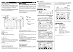
1
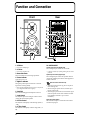
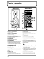
Owner’s Manual
Bedienungsanleitung
Mode d’emploi
Manuale d’uso
Manual del usuario
Thank you for purchasing the EDIROL Bi-Amp Monitor DM-5.
Before using this unit, carefully read the sections entitled: “IMPORTANT SAFETY
INSTRUCTIONS” (p. 2), “USING THE UNIT SAFELY” (p. 3–p. 4), and “IMPORTANT
NOTES” (p. 4–p. 5). These sections provide important information concerning the proper
operation of the unit. Additionally, in order to feel assured that you have gained a good
grasp of every feature provided by your new unit, this manual should be read in its
entirety. The manual should be saved and kept on hand as a convenient reference.
Main Features
● In Pursuit of High Sound Quality
The DM-5 powered monitor uses a two-way, bi-amplifier design to achieve high sound quality.
The monitor features a 120-mm LF Driver and a 19-mm soft-dome HF Driver as speakers. The
amplification includes 30-watt and 20-watt amplifiers designed to achieve high sound quality.
● Digital Input
In addition to XLR and TRS phone analog input, the DM-5 is provided with digital input connectors
(coaxial and optical) that support 96 kHz sample rate and 24-bit digital audio.
Digitally input signals are reproduced faithfully through 24-bit D/A conversion, thus preventing
noise or a drop in sound quality.
You can use the monitors with a wide variety of equipment and applications through selective use of
the analog and digital settings.
Contents
USING THE UNIT SAFELY................................................................3
IMPORTANT NOTES .........................................................................4
Function and Connection ................................................................6
Funktion und Anschlüsse................................................................8
Fonction et Connection..................................................................10
Funzionamento e Connessione.....................................................12
Función y conexión ........................................................................14
Reference ........................................................................................16
Copyright © 2001 ROLAND CORPORATION
All rights reserved. No part of this publication may be reproduced in any form without the
written permission of ROLAND CORPORATION.
CAUTION
RISK OF ELECTRIC SHOCK
DO NOT OPEN
ATTENTION: RISQUE DE CHOC ELECTRIQUE NE PAS OUVRIR
CAUTION: TO REDUCE THE RISK OF ELECTRIC SHOCK,
DO NOT REMOVE COVER (OR BACK).
NO USER-SERVICEABLE PARTS INSIDE.
REFER SERVICING TO QUALIFIED SERVICE PERSONNEL.
The lightning flash with arrowhead symbol, within an
equilateral triangle, is intended to alert the user to the
presence of uninsulated “dangerous voltage” within the
product’s enclosure that may be of sufficient magnitude to
constitute a risk of electric shock to persons.
The exclamation point within an equilateral triangle is
intended to alert the user to the presence of important
operating and maintenance (servicing) instructions in the
literature accompanying the product.
INSTRUCTIONS PERTAINING TO A RISK OF FIRE, ELECTRIC SHOCK, OR INJURY TO PERSONS.
IMPORTANT SAFETY INSTRUCTIONS
SAVE THESE INSTRUCTIONS
WARNING - When using electric products, basic precautions should always be followed, including the following:
1.
2.
3.
4.
5.
6.
7.
8.
9.
Read these instructions.
Keep these instructions.
Heed all warnings.
Follow all instructions.
Do not use this apparatus near water.
Clean only with a damp cloth.
Do not block any of the ventilation openings. Install in
accordance with the manufacturers instructions.
Do not install near any heat sources such as radiators,
heat registers, stoves, or other apparatus (including
amplifiers) that produce heat.
Do not defeat the safety purpose of the polarized or
grounding-type plug. A polarized plug has two blades with
one wider than the other. A grounding type plug has two
blades and a third grounding prong. The wide blade or the
third prong are provided for your safety. When the provided
plug does not fit into your outlet, consult an electrician for
replacement of the obsolete outlet.
10. Protect the power cord from being walked on or pinched
particularly at plugs, convenience receptacles, and the
point where they exit from the apparatus.
11. Only use attachments/accessories specified by the
manufacturer.
12. Never use with a cart, stand, tripod, bracket,
or table except as specified by the
manufacturer, or sold with the apparatus.
When a cart is used, use caution when
moving the cart/apparatus combination to
avoid injury from tip-over.
13. Unplug this apparatus during lightning storms or when
unused for long periods of time.
14. Refer all servicing to qualified service personnel. Servicing
is required when the apparatus has been damaged in any
way, such as power-supply cord or plug is damaged, liquid
has been spilled or objects have fallen into the apparatus,
the apparatus has been exposed to rain or moisture, does
not operate normally, or has been dropped.
For the U.K.
WARNING:
THIS APPARATUS MUST BE EARTHED
IMPORTANT: THE WIRES IN THIS MAINS LEAD ARE COLOURED IN ACCORDANCE WITH THE FOLLOWING CODE.
GREEN-AND-YELLOW: EARTH, BLUE: NEUTRAL, BROWN: LIVE
As the colours of the wires in the mains lead of this apparatus may not correspond with the coloured markings identifying
the terminals in your plug, proceed as follows:
The wire which is coloured GREEN-AND-YELLOW must be connected to the terminal in the plug which is marked by the
letter E or by the safety earth symbol or coloured GREEN or GREEN-AND-YELLOW.
The wire which is coloured BLUE must be connected to the terminal which is marked with the letter N or coloured BLACK.
The wire which is coloured BROWN must be connected to the terminal which is marked with the letter L or coloured RED.
2
USING THE UNIT SAFELY
The
symbol alerts the user to important instructions
or warnings.The specific meaning of the symbol is
determined by the design contained within the
triangle. In the case of the symbol at left, it is used for
general cautions, warnings, or alerts to danger.
Used for instructions intended to alert
the user to the risk of death or severe
injury should the unit be used
improperly.
Used for instructions intended to alert
the user to the risk of injury or material
damage should the unit be used
improperly.
* Material damage refers
other adverse effects
respect to the home
furnishings, as well
animals or pets.
The
symbol alerts the user to items that must never
be carried out (are forbidden). The specific thing that
must not be done is indicated by the design contained
within the circle. In the case of the symbol at left, it
means that the unit must never be disassembled.
to damage or
caused with
and all its
to domestic
The ● symbol alerts the user to things that must be
carried out. The specific thing that must be done is
indicated by the design contained within the circle. In
the case of the symbol at left, it means that the powercord plug must be unplugged from the outlet.
001
009
• Before using this unit, make sure to read the
instructions below, and the Owner’s Manual.
• Do not excessively twist or bend the power cord,
nor place heavy objects on it. Doing so can
damage the cord, producing severed elements and
short circuits. Damaged cords are fire and shock
hazards!
..........................................................................................................
..........................................................................................................
002a
• Do not open or perform any internal modifications on the unit.
..........................................................................................................
003
• Do not attempt to repair the unit, or replace parts
within it (except when this manual provides
specific instructions directing you to do so). Refer
all servicing to your retailer, the nearest Roland/
EDIROL Service Center, or an authorized Roland/
EDIROL distributor, as listed on the “Information” page.
..........................................................................................................
004
• Never use or store the unit in places that are:
• Subject to temperature extremes (e.g., direct
sunlight in an enclosed vehicle, near a heating
duct, on top of heat-generating equipment); or
are
• Damp (e.g., baths, washrooms, on wet floors);
or are
• Humid; or are
• Exposed to rain; or are
• Dusty; or are
• Subject to high levels of vibration.
..........................................................................................................
007
• Make sure you always have the unit placed so it is
level and sure to remain stable. Never place it on
stands that could wobble, or on inclined surfaces.
..........................................................................................................
010
• This unit, either alone or in combination with an
amplifier and headphones or speakers, may be
capable of producing sound levels that could
cause permanent hearing loss. Do not operate for
a long period of time at a high volume level, or at
a level that is uncomfortable. If you experience
any hearing loss or ringing in the ears, you should
immediately stop using the unit, and consult an
audiologist.
..........................................................................................................
011
• Do not allow any objects (e.g., flammable material,
coins, pins); or liquids of any kind (water, soft
drinks, etc.) to penetrate the unit.
..........................................................................................................
013
• In households with small children, an adult
should provide supervision until the child is
capable of following all the rules essential for the
safe operation of the unit.
..........................................................................................................
014
• Protect the unit from strong impact.
(Do not drop it!)
..........................................................................................................
008a
• The unit should be connected to a power supply
only of the type described in the operating instructions, or as marked on the unit.
3
015
106
• Do not force the unit’s power-supply cord to share
an outlet with an unreasonable number of other
devices. Be especially careful when using
extension cords—the total power used by all
devices you have connected to the extension
cord’s outlet must never exceed the power rating
(watts/amperes) for the extension cord. Excessive
loads can cause the insulation on the cord to heat
up and eventually melt through.
..........................................................................................................
• Never climb on top of, nor place heavy objects on
the unit.
016
• Before using the unit in a foreign country, consult
with your retailer, the nearest Roland/EDIROL
Service Center, or an authorized Roland/EDIROL
distributor, as listed on the “Information” page.
..........................................................................................................
..........................................................................................................
107b
• Never handle the power cord or its plugs with wet
hands when plugging into, or unplugging from,
an outlet or this unit.
..........................................................................................................
108a
• Before moving the unit, disconnect the power
plug from the outlet, and pull out all cords from
external devices.
..........................................................................................................
109a
• Before cleaning the unit, turn off the power and
unplug the power cord from the outlet.
..........................................................................................................
110a
101a
• The unit should be located so that its location or
position does not interfere with its proper ventilation.
..........................................................................................................
102b
• Always grasp only the plug on the power-supply
cord when plugging into, or unplugging from, an
outlet or this unit.
..........................................................................................................
104
• Whenever you suspect the possibility of lightning
in your area, pull the plug on the power cord out
of the outlet.
..........................................................................................................
118
• Should you remove the optical connector cap,
make sure to put them in a safe place out of
children's reach, so there is no chance of them
being swallowed accidentally.
..........................................................................................................
• Try to prevent cords and cables from becoming
entangled. Also, all cords and cables should be
placed so they are out of the reach of children.
..........................................................................................................
IMPORTANT NOTES
291b
In addition to the items listed under “IMPORTANT SAFETY INSTRUCTIONS” and “USING THE UNIT SAFELY” on pages 3
and 4, please read and observe the following:
Power Supply
301
• Do not use this unit on the same power circuit with any
device that will generate line noise (such as an electric
motor or variable lighting system).
307
• Before connecting this unit to other devices, turn off the
power to all units. This will help prevent malfunctions
and/or damage to speakers or other devices.
Placement
352
• This device may interfere with radio and television
reception. Do not use this device in the vicinity of such
receivers.
4
354b
• Do not expose the unit to direct sunlight, place it near
devices that radiate heat, leave it inside an enclosed
vehicle, or otherwise subject it to temperature extremes.
Also, do not allow lighting devices that normally are
used while their light source is very close to the unit
(such as a piano light), or powerful spotlights to shine
upon the same area of the unit for extended periods of
time. Excessive heat can deform or discolor the unit.
355
• To avoid possible breakdown, do not use the unit in a wet
area, such as an area exposed to rain or other moisture.
356
• Do not allow rubber, vinyl, or similar materials to remain
on the unit for long periods of time. Such objects can
discolor or otherwise harmfully affect the finish.
IMPORTANT NOTES
357
• Do not put anything that contains water (e.g., flower
vases) on the unit. Also, avoid the use of insecticides,
perfumes, alcohol, nail polish, spray cans, etc., near the
unit. Swiftly wipe away any liquid that spills on the unit
using a dry, soft cloth.
359
• Do not paste stickers, decals, or the like to this
instrument. Peeling such matter off the instrument may
damage the exterior finish.
• During Operation, this device must be placed at a
distance of no less than 50 cm from any walls.
• Do not allow objects to remain on top of the unit while it
is in operation.
• If you cover the heat sink, their function is defeated,
and their temperature can rise to overly high levels,
which could cause burns if they are accidentally
touched.
• Placing heavy objects on this unit may result in injury
if it overturns or falls.
• During setup and transport, be careful not to damage the
vibrating portions (the speaker cone and diaphragm).
• Be sure to place the monitor so that the heat sink on the
rear panel is not obstructed. Also, make sure the monitor
does not touch any curtains or other fabrics.
• The heat sink performs cooling when the monitor is
placed as shown below. Do not place the monitor on its
side or upside down.
fig.06.e
Heated Air
Maintenance
401a
• For everyday cleaning wipe the unit with a soft, dry cloth
or one that has been slightly dampened with water. To
remove stubborn dirt, use a cloth impregnated with a
mild, non-abrasive detergent. Afterwards, be sure to
wipe the unit thoroughly with a soft, dry cloth.
402
• Never use benzine, thinners, alcohol or solvents of any
kind, to avoid the possibility of discoloration and/or
deformation.
Additional Precautions
553
• Use a reasonable amount of care when using the unit’s
buttons, sliders, or other controls; and when using its
jacks and connectors. Rough handling can lead to
malfunctions.
556
• When connecting / disconnecting all cables, grasp the
connector itself—never pull on the cable. This way you
will avoid causing shorts, or damage to the cable’s
internal elements.
557
• A small amount of heat will radiate from the unit during
normal operation.
558b
• To avoid disturbing your neighbors, try to keep the unit’s
volume at reasonable levels (especially when it is late at
night).
559a
• When you need to transport the unit, package it in the
box (including padding) that it came in, if possible.
Otherwise, you will need to use equivalent packaging
materials.
562
• Use a cable from Roland to make the connection. If using
some other make of connection cable, please note the
following precautions.
• Some connection cables contain resistors. Do not use
cables that incorporate resistors for connecting to this
unit. The use of such cables can cause the sound level
to be extremely low, or impossible to hear. For information on cable specifications, contact the manufacturer of the cable.
• When this device is in operation, the heat sink located on
the rear panel will become hot. Take care not to touch
them with your hands.
5
Function and Connection
Front
Rear
6
1
7
8
9
14
15
16
10
11
12
2
3
4
5
13
fig.03.e
1. HF Driver
10. DIGITAL INPUT
* Do not touch the diaphragm.
Coaxial Input Connector (Digital Input)
This is the digital input connector for coaxial cable.
2. LF Driver
* Do not touch the speaker cone.
3. Bass-reflex Ducts
These are conduits for rich, bass-range reproduction.
4. Power Indicator
Lights when power is on.
5. Digital In Indicator
This lights up when output is received from a connected
digital device or during standby.
* When the connected digital-signal output device is not powered
up, the Digital In indicator does not light up.
6. Heat Sink
This is a heat-radiating plate that dissipates excess heat.
7. Level Control
This adjusts the input level. Turning the control clockwise
increases the sound from the speakers.
8. HF Trim Control
This adjusts the sound quality of the treble range (10 kHz, +/
-3 dB).
9. LF Trim Control
This adjusts the sound quality of the bass range (80 Hz, +/-3
dB).
6
* It cannot be used for input of analog audio signals (no sound is
produced).
Optical Input Connector (Digital Input)
This is the digital input connector for optic-fiber cable. Use
commercially available optical cable for audio equipment to
make the connection.
Optical-connector Protective Cap
• After removing the protective cap, put in a safe place so
that it doesn’t get lost.
• When not using the optical connector, attach the cap to
keep the connector safe.
• When using the optical connector, be sure that the cap you
removed is placed out of the reach of children. If a child
has accidentally swallowed a cap, see a doctor
immediately.
Digital Input Select Switch
This switch selects Optical or Coaxial. Select the connector
used for the input signal.
Function and Connection
11. Power Switch
This switch turns the power on/off.
12. AC Inlet
Connect the included Power cord here. Plug it firmly in, so
that the cable does not accidentally become disconnected.
13. Power Cord
This box contains continental and British power cables.
Please select the correct type for your country.
14. Input Select Switch
Used to select Digital Input or Analog Input.
Select the connector used for the input signal.
XLR/TRS Phone Input Connector (Analog Input)
This is for connecting XLR or
TRS phone plugs.
Both balanced and unbalanced
XLR type
connections are possible.
* The pin assignment for the
connector is as shown below.
Before making any connections,
make sure that this pin
assignment is compatible with
that of all your other devices.
English
* With the DM-5, there is no difference between L and R.
When using the digital input connectors of two DM-5 monitors
for stereo sound, the digital signal can be input to either L or R.
15. ANALOG INPUT
TRS
Phone type phone type
(Unbalanced) (Balanced)
GND (SLEEVE)
1: GND
2: HOT
3: COLD
HOT (TIP)
COLD (RING)
16. Thru (Digital Out) Connector
When connecting multiple DM-5 monitors with digital
signals, this connector is used for output to the second DM-5.
Deutsch
Assign Switch
This switch selects the stereo position of the digital signal.
It selects Right, L+R, or Left when using two DM-5 monitors
for stereo sound (with digital signals).
Choose the setting appropriate for your setup.
(When turning the power off, reverse this procedure.)
<Connected devices → DM-5>
• This unit is equipped with a protection circuit. A brief
interval (a few seconds) after power up is required before
the unit will operate normally.
Français
● Precautions When Connecting and Turning on the Power
• To prevent malfunction and/or damage to speakers or
other devices, always turn down the volume, and turn off
the power on all devices before making any connections.
• Once the connections have been completed, turn on
power to your various devices in the order specified. By
turning on devices in the wrong order, you risk causing
malfunction and/or damage to speakers and other
devices.
Using Two DM-5 Monitors for Stereo Sound
Example for
Using Digital Input Connectors
Italiano
Example for
Using Analog Input Connectors
Español
Select
DIGITAL IN
(COAXIAL)
THRU
(DIGITAL OUT)
DV-7
DIGITAL IN
(COAXIAL)
(OPTICAL)
DIGITAL OUT
CD Player, MD Player, etc.
7
Funktion und Anschlüsse
Vorderseite
Rückseite
6
1
7
8
9
14
15
16
10
11
12
2
3
4
5
13
fig.03.g
1. HF-Treiber
10. DIGITAL INPUT
* Die Membrane nicht ber hren.
Coaxial-Anschluss
Dies ist der digitale Anschluss für Coaxial-Kabel.
2. LF-Treiber
* Die Membrane nicht ber hren.
3. Bass-Reflex-Öffnungen
Die ffnungen sorgen f r eine volle Bass-Wiedergabe.
4. Power-Anzeige
Leuchtet auf, wenn die Box eingeschaltet ist.
5. Digital-In-Anzeige
Leuchtet w hrend des Standby-Betriebs auf oder, wenn ein
Signal vom Ausgang eines angeschlos-senen Digital-Ger tes
empfangen wird.
* Wenn das angeschlossene Digital-Ger t nicht eingeschaltet ist,
leuchtet die Digital-In-Anzeige nicht auf.
6. Kühlkörper
Der Kühlkörper leitet überschüssige Hitze ab.
7. Input Level-Regler
Damit stellen Sie die Lautstärke ein. Je weiter Sie den Regler
im Uhrzeigersinn drehen, desto höher wird die Lautstärke.
8. HF Trim-Regler
Hier können Sie die Höhen nach Wunsch einstellen (10 kHz,
±3 dB).
9. LF Trim-Regler
Hier können Sie die Bässe nach Wunsch einstellen (80 Hz, ±3
dB).
8
* Der Anschluss ist nicht für analoge Signale geeignet; analoge
Signale werden hier nicht wiedergegeben.
Optical-Anschluss
Dies ist der digitale Anschluss für handelsübliche optische
Kabel, wie sie im Audio-Bereich verwendet werden.
Schutzkappe für den Optical-Anschluss
• Bewahren Sie diese nach dem Abziehen gut auf, damit sie
nicht verlorengeht.
• Belassen Sie die Kappe auf dem Anschluss, wenn Sie ihn
nicht benutzen, damit er gut geschützt ist.
• Halten Sie die abgezogene Kappe von Kindern fern. Falls
ein Kind die Schutzkappe versehentlich ver-schluckt
haben sollte, suchen Sie unverzüglich einen Arzt auf.
Digital-Input-Wahlschalter
Schaltet zwischen Optical und Coaxial um. Wählen Sie hier
den Anschluss des Eingangssignals.
Assign-Schalter
Hier legen Sie die Stereo-Position des Digitalsignals fest. Sie
haben bei der Verwendung von zwei DM-5-Moni-toren die
Wahl zwischen Right (rechts), L+R (links + rechts) und Left
(links).
Funktion und Anschlüsse
12. Netzbuchse
Hier schließen Sie das mitgelieferte Stromkabel an. Stecken
Sie es fest in die Buchse, damit es sich nicht
unbeabsichtigterweise lösen kann.
13. Netzkabel
Diese Packung beinhaltet europäische und britische
Netzkabel. Bitte suchen Sie sich die richtige Variante für Ihr
Land aus.
14. Input Select-Schalter
Hier schalten Sie zwischen Digital Input (Digital-Eingang)
und Analog Input (Analog-Eingang) um. Wählen Sie den
Anschluss des Eingangssignals aus.
XLR/TRS-Klinkenstecker-Anschluss
Hier können Sie XLR- sowie TRS(stereo) und einfache (mono)
Klinkenstecker anschließen.
Es sind symmetrische und
unsymmetrische Verbindungen möglich.
English
11. Power-Schalter
Mit diesem Schalter schalten Sie die DM-5 ein oder aus.
15. ANALOG INPUT
XLR-Stecker
* Die Pin-Belegung ist wie unten
abgebildet. Vergewissern Sie
Klinkenstecker
(unsymmetrisch)
sich, dass die Pin-Belegung mit
der Ihrer anderen Geräte
übereinstimmt, bevor Sie diese hier anschließen.
TRSKlinkenstecker
(symmetrisch)
GND (SLEEVE)
1: GND
2: HOT
3: COLD
HOT (TIP)
Deutsch
* Ein DM-5-Monitor kann für beide Stereo-Kanäle benutzt
werden und unterscheidet nicht von selbst zwischen links und
rechts. Stellen Sie den „Assign“-Schalter für ein digitales
Eingangssignal nach Bedarf auf „L“ oder „R“.
COLD (RING)
16. Thru (Digital Out)-Buchse
Beim digitalen Verbinden mehrerer DM-5 wird das Sig-nal
über diese Buchse zur zweiten DM-5 weitergeleitet.
● Vorsichtsmaßnahmen beim Anschließen und Einschalten
allen beteiligten Komponenten.
(Die Geräte in umgekehrter Reihenfolge ausschalten.)
• Die Monitore besitzen eine Schutzschaltung. Es dauert
daher einige Sekunden, bis sie normal arbeiten.
Français
• Um eine Fehlfunktion und/oder Beschädigung der Lautsprecher und anderer Geräte zu vermeiden, drehen Sie die
Lautstärke ganz ab und schalten alle Geräte aus, bevor Sie
diese verkabeln.
• Wenn Sie alle Geräte miteinander verkabelt haben,
schalten Sie zunächst alle angeschlossenen Geräte und
zuletzt die DM-5-Monitore ein. Wenn Sie sich nicht an
diese Reihenfolge halten, riskieren Sie Beschädigungen an
Zwei DM-5-Monitore für Stereo-Wiedergabe einsetzen
Beispiel für die Verwendung
der analogen Eingänge
Italiano
Beispiel für die Verwendung
der analogen Eingänge
Español
Auswählen
DIGITAL IN
(COAXIAL)
THRU
(DIGITAL OUT)
DV-7
DIGITAL IN
(COAXIAL)
(OPTICAL)
DIGITAL OUT
CD Player, MD Player, etc.
9
Fonction et Connection
Avant
Arriére
6
1
7
8
9
14
15
16
10
11
12
2
3
4
5
13
fig.03.f
1. Tweeter
10. DIGITAL INPUT
* Ne pas toucher le diaphragme.
Connecteur d’entrée Coaxial (Entrée numérique)
Connecteur d’entrée numérique pour un câble coaxial.
2. Boomer
* Ne pas toucher le cône.
3. Events Bass-Reflex
Ce sont des trous pour une reproduction des graves riche.
4. Indicateur Power
S’allume lors de la mise sous tension.
5. Indicateur Digital In
Il s’allume lorsque le signal est reçu d’un appareil numérique
ou en mode “Standby.”
* Lorsque l’appareil numérique relié n’est pas sous tension,
l’indicateur Digital In ne s’allume pas.
6. Radiateur
Ce radiateur plat dissipe la chaleur excessive.
7. Contrôle Input Level
Règle le niveau d’entrée. Tournez le bouton dans le sens des
aiguilles d’une montre pour augmenter le volume.
8. Contrôle HF Trim
Règle le gain des aigus (10 kHz, +/-3 dB).
9. Contrôle LF Trim
Règle le gain des basses (80 Hz, +/-3 dB).
10
* Il ne peut pas être utilisé pour les signaux analogiques (aucun
son n’est reproduit).
Connecteur d’entrée Optique (Entrée numérique)
Connecteur d’entrée numérique pour une fibre optique.
Utilisez des fibres optiques pour appareils audio du
commerce pour les connexions.
Bouchon de Protection
• Lorsque vous enlevez le bouchon de protection, mettez-le
en lieu sûr afin de ne pas le perdre.
• Lorsque l’entrée optique n’est pas utilisée, mettez le
bouchon de protection pour protéger le connecteur.
• Lorsque vous utilisez l’entrée optique, veillez à ce que le
bouchon que vous enlevez soit hors de portée des enfants.
Si un enfant a avalé par accident le bouchon, consultez
immédiatement un médecin.
Interrupteur de Sélection d’Entrée Numérique
Cet interrupteur détermine l’entrée Coaxiale ou Optique.
Sélectionnez le connecteur utilisé pour le signal d’entrée.
Interrupteur Assign
Détermine la position stéréo du signal numérique. Il permet de
sélectionner Droite (Right), Gauche + Droite (L+R) ou Gauche
(Left) en utilisant deux DM-5 en stéréo (en numérique).
Sélectionnez le réglage approprié.
15. ANALOG INPUT
* Avec les DM-5, il n’y a pas de différence entre la gauche et la
droite. En utilisant les entrées numériques sur deux DM-5 pour
la stéréo, le signal numérique peut être entré soit à droite soit à
gauche.
Connecteur d’entrée XLR/Jack stéréo (Entrée analogique)
Utilisé pour des prises XLR ou
Jack 6,35mm stéréo.
Les connexions symétriques et
Prise XLR
asymétriques sont acceptées.
Cet interrupteur allume et éteint l’enceinte.
12. Prise Secteur
Reliez le cordon secteur fourni ici. Enfoncez-le à fond, de
façon à ce que le câble ne se débranche pas inopinément.
13. Cordon Secteur
Cette boite contient des alimentations anglaises ou
continentales. Merci de choisir l’alimentation appropriée de
votre pays.
* L’assignation des broches des
connecteurs est indiquée ci-dessous.
Avant toute connexion, vérifiez que
cette assignation est compatible
avec celle de vos appareils.
Masse (Corps)
1: Masse
2: Chaud
3: Froid
Chaud
(bout)
14. Interrupteur Input Select
Utilisé pour choisir l’entrée analogique ou numérique.
Sélectionnez le connecteur utilisé pour le signal d’entrée.
Jack Stéréo
Jack Mono (Symétrique)
(Asymétrique)
Froid (anneau)
16. Connecteur Thru (Digital Out)
Lors de la connexion de plusieurs DM-5 avec des signaux
numériques, ce connecteur est utilisé pour sortir vers la
seconde DM-5.
Deutsch
11. Interrupteur Power
English
Fonction et Connection
• Pour éviter d’endommager et/ou tout mauvais
fonctionnement des écoutes ou autres appareils, baissez
toujours le volume, et éteignez tous les appareils avant de
faire vos connexions.
• Une fois les connexions terminées, mettez sous tension
vos différents appareils dans l’ordre spécifié. En allumant
les appareils dans le mauvais ordre, vous pouvez
endommager et/ou engendrer un mauvais
fonctionnement des enceintes et autres appareils. (Lors de
la mise hors tension, inversez la procédure).
<Appareils Connectés → DM-5>
• Cet appareil possède un circuit de protection. Quelques
secondes sont nécessaires à la mise sous tension pour que
l’appareil fonctionne normalement.
Français
● Précautions lors de la Connexion et de la Mise sous Tension
Utilisation de Deux Ecoutes DM-5 pour la Stéréo
Exemple d'Utilisation des
Entrées Numériques
Italiano
Exemple d'Utilisation des
Entrées Analogiques
Español
Select
DIGITAL IN
(COAXIAL)
THRU
(DIGITAL OUT)
DV-7
DIGITAL IN
(COAXIAL)
(OPTICAL)
DIGITAL OUT
Lecteur CD, MiniDisk, etc.
11
Funzionamento e Connessione
Anteriore
Posteriore
6
1
7
8
9
14
15
16
10
11
12
2
3
4
5
13
fig.03.i
1. Driver HF
9. Controllo LF Trim
* Non toccate il diaframma.
Regola la qualita sonora della gamma dei bassi (80 Hz, +/-3
dB).
2. Driver LF
* Non toccate il cono dell’altoparlante.
3. Dotti Bass-reflex
Sono condotti per una riproduzione ricca dellagamma dei
bassi.
4. Indicatore Power
Si illumina ad unità accesa.
5. Indicatore Digital In
Si accende quando l’uscita viene ricevuta da un dispositivo
digitale collegato o durante lo standby.
* Quando il dispositivo che emette il segnale digitale è spento,
l’indicatore Digital In non si accende.
6. Dispersore di Calore
E una piastra che irradia il calore per dissipare il calore in
eccesso.
7. Controllo del Livello d’Ingresso
Regola il livello d’ingresso. Ruotando il controllo in senso
orario aumenta in suono dai diffusori.
8. Controllo HF Trim
Regola la qualita sonora della gamma degli acuti (10 kHz, +/
-3 dB).
12
10. DIGITAL INPUT
Connettore d’Ingresso Coassiale (Ingresso Digitale)
Questo e il connettore d’ingresso digitale per il cavo
coassiale.
* Non puo essere usato per l’ingresso di segnali analogici audio
(non si produce alcun suono).
Connettore d’Ingresso Ottico (Ingresso Digitale)
Questo e il connettore d’ingresso digitale per il cavo a fibra
ottica. Usate un cavo ottico disponibile in commercio per
apparecchiature audio per eseguire il collegamento.
Cappuccio di Protezione del Connettore Ottico
• Dopo aver rimosso il cappuccio protettivo, mettetelo in un
posto sicuro cosi da non perderlo.
• Quando non usate il connettore ottico, mettete il
cappuccio per proteggere il connettore.
• Quando usate il connettore ottico, tenete il cappuccio
lontano dai bambini. Se un bambino ha ingoiato accidentalmente il cappuccio, consultate subito un dottore.
Interruttore Selezione Ingresso Digitale
Questo interruttore seleziona Ottico o Coassiale. Selezionate
il connettore usato per il segnale in ingresso.
Funzionamento e Connessione
11. Interruttore Power
Accende e spegne l’unita.
12. Presa CA
Collegate qui il cavo di alimentazione incluso. Infilatelo
saldamente, cosi che il cavo non si sfili accidentalmente.
Connettore d’Ingresso XLR/TRS Phone (Ingresso Analogico)
Per il collegamento di spine XLR
o TRS phone.
Sono possibili sia collegamenti
Tipo XLR
bilanciati o sbilanciati.
* L’assegnazione dei pin per il
connettore e riportata sotto.
Prima di eseguire i collegamenti,
TRS
Tipo phone tipo phone
assicuratevi che questa
(Sbilanciato) (Bilanciato)
assegnazione dei pin sia
compatibile cono quella degli altri vostri dispositivi.
MASSA (GUAINA)
1: MASSA
2: CALDO
3: FREDDO
13. Cavo Alimentazione
La confezione contiene alimentatori con spina europea e
Inglese. Scegliete quella adatta alla Vostra nazione.
14. Interruttore Selezione Ingresso
Usato per selezionare Ingresso Digitale o Ingresso Analogico.
Selezionate il connettore usato per immettere il segnale.
English
* Col DM-5, non vi e differenza tra L ed R. Usando in connettori
d’ingresso digitale di due monitor DM-5 per il suono stereo, il
segnale digitale puo essere immesso in L o in R (Sinistra - Destra).
15. ANALOG INPUT
CALDO
(PUNTA)
FREDDO (ANELLO)
16. Connettore Thru (Uscita Digitale)
Nel collegare piu monitor DM-5 con segnali digitali, questo
connettore e usato per l’uscita al secondo DM-5.
Deutsch
Interruttore Assign
Questo interruttore seleziona la posizione stereo del segnale
digitale. Seleziona Right, L+R, o Left usando due monitor
DM-5 per il suono stereo (con segnali digitali).
Scegliete l’impostazione appropriata al vostro setup.
● Precauzioni nel Collegamento e nell’Accensione
(Per spegnere, invertite la procedura.)
<Dispositivi collegati → DM-5>
• Questa unita e dotata di un circuito di protezione. E
necessario un breve intervallo (pochi secondi) dopo
l’accensione prima che l’unita funzioni normalmente.
Français
• Per evitare malfunzionamenti e/o danni ai diffusori o ad
altri dispositivi, abbassate sempre il volume, e spegnete
tutti i dispositivi prima di eseguire qualsiasi collegamento.
• Completati i collegamenti, accendete i vari dispositivi
nell’ordine specificato. Accendendo i dispositivi
nell’ordine sbagliato, rischiate di provocare
malfunzionamenti e/o danni ai diffusori o ad altri
dispositivi.
Usare Due Monitor DM-5 per il Suono Stereo
Esempio dell'Uso dei
Connettori d'Ingresso Digitali
Italiano
Esempio dell'Uso dei
Connettori d'Ingresso Analogici
Selettore
THRU
(DIGITAL OUT)
DV-7
Español
DIGITAL IN
(COAXIAL)
DIGITAL IN
(COAXIAL)
(OPTICAL)
DIGITAL OUT
Riproduttore CD, Riproduttore MD, etc.
13
Función y conexión
Parte Frontal
Parte Posterior
6
1
7
8
9
14
15
16
10
11
12
2
3
4
5
fig.03.s
13
1. Altavoz de Frecuencias Altas
9. Control LF Trim
* No toque el diafragma.
(Recorte de las Frecuencias Graves)
Ajusta la calidad de sonido del registro de graves (80 Hz, +/3 dB).
2. Altavoz de Frecuencias Bajas
* No toque el cono del altavoz.
3. Conductos de reflexión de graves
Estos son conductos que proporcionan una reproducción de
alta calidad del registro de graves.
4. Indicador Power
Se ilumina cuando se enciende el aparato.
5. Indicador Digital In
Se ilumina cuando se recibe una señal de un aparato digital
conectado a la unidad o cuando está en estado de espera.
* Cuando el aparato que genera señales digitales está conectado
pero no encendido, el indicador Digital In no se ilumina.
6. Placa Disipadora de Calor
Esto es una placa disipadora de calor que sirve para disipar
el calor excesivo.
7. Control Input Level
Ajusta el nivel de entrada. Girando el control en el sentido de
las agujas del reloj sube el nivel de sonido procedente de los
altavoces.
8. Control HF Trim
(Recorte de las Frecuencias Agudos)
Ajusta la calidad de sonido del registro de agudos (10 kHz,
+/-3 dB).
14
10. DIGITAL INPUT
Conector de Entrada Coaxial (Entrada Digital)
Es el conector de entrada digital para cable coaxial.
* No se puede utilizar para entrar señales de audio analógicas (no
produce sonido).
Conector de Entrada óptica (Entrada Digital)
Es el conector de entrada digital para cable de fibra óptica.
Utilice un cable óptico específico para aplicaciones de audio
para realizar la conexión.
Tapa Protectora del Conector Óptico
• Después de quitar la tapa protectora, guárdela en un lugar
seguro para no perderla.
• Cuando no está utilizando el conector óptico, ponga la
tapa para proteger el conector.
• Cuando utilice el conector óptico, asegúrese de que la tapa
que haya quitado quede fuera del alcance de los niños. Si
un niño ingiere la tapa, avise a un médico
inmediatamente.
Interruptor de Selección de Entrada Digital
Este interruptor selecciona la entrada Óptica o Coaxial.
Seleccione el conector utilizado para la señal de entrada.
Interruptor de Asignación
Este interruptor selecciona la posición de la señal digital en el
campo estereofónico. Seleccione Right (derecha), L+R (izquierda
+ derecha), o Left (izquierda) cuando utiliza dos monitores DM5 para logra un sonido estéreo (con señales digitales).
Seleccione la posición de acuerdo con la configuración de su equipo.
15. ANALOG INPUT
* En el DM-5 no existe distinción entre izquierda y derecha.
Cuando se utiliza los conectores de entrada digital de dos
monitores DM-5 para logra un sonido estéreo, se la señal digital
puede enviarse hacia la izquierda o la derecha.
* La asignación de pins para el
conector esta indicado a
continuación. Antes de hacer
Tipo fono
Tipo Fono
TRS
cualquier conexión, compruebe
no balanceado balanceado
que esta asignación de pins es
compatible con todos sus otros aparatos.
11. Interruptor Power
Este interruptor enciende y apaga el aparato.
Conector de Entrada para XLR / fono TRS (Entrada Analógica)
Sirve para conectar jacks de tipo
XLR o fono TRS.
Son posibles las conexiones
Tipo canon XLR
balanceadas y no balanceadas.
English
Función y conexión
1: Toma de Tierra
Positivo
2: Positivo
3: Negativo
(punta)
Conecte aquí el cable de alimentación que se suministra con
el DM-5. Asegúrese de que esté conectado correctamente
para que el cable no se desconecte accidentalmente.
13. Cable de Alimentación
Esta caja contiene cables de corriente continentales y
británicos. Por favor seleccione el tipo correcto para su país.
14. Interruptor Input Select
Negativo (anillo)
16. Conector Thru (Salida Digital)
Cuando tiene conectados múltiples monitores DM-5 con
señales digitales, este conector se utiliza como salida hacia el
segundo DM-5.
Deutsch
Toma de Tierra (manga)
12. Entrada AC
Su función es seleccionar Entrada Digital o Entrada Analógica.
Seleccione el conector utilizado para la señal de entrada.
• Para prevenir el mal funcionamiento y/o daños a los
altavoces u otros aparatos, siempre bajar el volumen, y
apagar todos los aparatos antes de hacer cualquier
conexión.
• Una vez completadas los conexiones, encienda sus
aparatos siguiendo el orden especificado. Si se enciende
los aparatos en un orden equivocado, corre el riesgo de
provocar el mal funcionamiento de los altavoces u otros
aparatos o incluso de dañarlos. (Cuando apaga los
aparatos haga este procedimiento al revés.
<Aparatos conectados → DM-5>
• Esta unidad viene equipada con un circuito de seguridad.
Al encenderla, tardará un intervalo de tiempo breve (unos
cuantos segundos) hasta funcionar con normalidad.
Français
● Precauciones al Conectar y Encender la Unidad
Utilizar Dos Monitores DM-5 para Conseguir Sonido en Estéreo
Ejemplo Para Utilizar Conectores
de Entrada Digitales
Italiano
Ejemplo Para el Uso de Conectores
de Entrada Analógicos
Español
Selección
DIGITAL IN
(COAXIAL)
THRU
(DIGITAL OUT)
DV-7
DIGITAL IN
(COAXIAL)
(OPTICAL)
DIGITAL OUT
Lector de CD, MiniDisk, etc.
15
Reference
Troubleshooting
If there is no sound or if the unit does not operate as you expect, please check the following points
first. If this does not resolve the problem, contact the nearest Roland/EDIROL service center or
authorized Roland/EDIROL distributor.
There’s No Sound
• Make sure the Input Level control has not been turned fully counterclockwise.
• Make sure the Input Select switch has been set to the connector where the input signal is
connected (Digital Input or Analog Input).
• Make sure the Digital Input select switch has been set to the connector where the input signal is
connected (Optical or Coaxial).
• Input a digital signal to the Digital Input connector. No sound is produced when an analog signal
is input.
The volume level of the instrument connected to ANALOG INPUT is
too low
• Could you be using a connection cable that contains a resistor? Use a connection cable that does
not contain a resistor.
During Digital Signal Input, the Stereo Image Is Reversed or
Sounds Unnatural, or Output Doesn’t Sound Like Stereo
• Check the setting of the Assign switch (Right, L+R, or Left). The DM-5 uses an identical
construction for the left and right monitors, and makes no distinction between left and right.
During digital signal input, set the Assign switch L or R as appropriate for your setup.
16
Reference
Specifications
● System
● Power Supply
2 Way Bi-Amplified Monitor
AC117 V, AC230 V or AC240 V
● Enclosure
● Power Consumption
Bass-reflex type
50 W
● Cabinet
● Dimensions
1/2” MDF, Baffle: 3/4” MDF
197 (W) x 267 (D) x 312 (H) mm
7-3/4 (W) x 10-1/2 (D) x 12-1/4 (H) inches
● LF Driver
120 mm (5”) Foamed polypropylene cone type, magnetically
shielded
● Weight
● HF Driver
● Accessories
19 mm (3/4”) soft dome type, magnetically shielded
Owner’s Manual
Power Cord
● Frequency Response
8 kg / 17 lbs. 11 oz.
68 Hz to 22 kHz (+/-3 dB)
● Crossover Frequency
2.3 kHz (active third order)
● LF Amplifier Power
30 W
Application of AC230 V
Power Cord
● HF Amplifier Power
20 W
Analog in
● Input Sensitivity
◆◆◆◆◆
◆◆◆◆◆◆◆◆◆◆◆◆◆◆◆◆◆◆◆◆◆◆◆◆◆◆◆◆
0 dBu (0.775 Vrms)
● Input Impedance
20 k ohms (Balanced/Unbalanced)
for UK
◆◆◆◆◆◆◆◆◆◆◆◆◆◆◆◆◆◆◆◆◆◆◆◆◆◆◆◆◆◆◆◆◆◆◆◆◆◆◆◆◆◆◆◆◆◆◆◆◆◆◆
Digital in
● Format
◆◆◆◆◆
◆◆◆◆◆◆◆◆◆◆◆◆◆◆◆◆◆◆◆◆◆◆◆◆◆◆◆◆◆
Conformity with S/P DIF
● Sample Rate
32 kHz to 96 kHz (de-emphasis: OFF)
● D/A Converter
24-bit
◆◆◆◆◆◆◆◆◆◆◆◆◆◆◆◆◆◆◆◆◆◆◆◆◆◆◆◆◆◆◆◆◆◆◆◆◆◆◆◆◆◆◆◆◆◆◆◆◆◆◆
● Controls
LEVEL Knob
LF TRIM Knob (80 Hz, +/-3 dB)
HF TRIM Knob (10 kHz, +/-3 dB)
INPUT SELECT SW (Analog In/Digital In)
ASSIGN SW (Right/L+R/Left)
DIGITAL INPUT SELECT SW (Optical/Coaxial)
POWER SW
except for UK
● Indicators
POWER
DIGITAL IN
● Connectors
ANALOG INPUT (XLR/TRS PHONE, Balanced/
Unbalanced)
DIGITAL INPUT (Optical)
DIGITAL INPUT (Coaxial)
DIGITAL THRU OUT (Coaxial)
* In the interest of product improvement, the specifications and/or
appearance of this unit are subject to change without prior
notice.
17
Reference
Dimensions
fig.08.e
197 (7-3/4")
261 (10-1/4")
312
(12-1/4")
6
(1/4")
267 (10-1/2")
* Not include the Power cord.
Frequency Response
fig.ftoku
(dB)
20
Response
HF: max
flat
LF: max
flat
10
0
LF: min
HF: min
-10
-20
-30
20
50
100
200
500
1k
Frequency
18
2k
5k
10k
20k
(Hz)
For EU Countries
This product complies with the requirements of European Directives EMC 89/336/EEC and LVD 73/23/EEC.
For the USA
FEDERAL COMMUNICATIONS COMMISSION
RADIO FREQUENCY INTERFERENCE STATEMENT
This equipment has been tested and found to comply with the limits for a Class B digital device, pursuant to Part 15 of the
FCC Rules. These limits are designed to provide reasonable protection against harmful interference in a residential
installation. This equipment generates, uses, and can radiate radio frequency energy and, if not installed and used in
accordance with the instructions, may cause harmful interference to radio communications. However, there is no guarantee
that interference will not occur in a particular installation. If this equipment does cause harmful interference to radio or
television reception, which can be determined by turning the equipment off and on, the user is encouraged to try to correct the
interference by one or more of the following measures:
– Reorient or relocate the receiving antenna.
– Increase the separation between the equipment and receiver.
– Connect the equipment into an outlet on a circuit different from that to which the receiver is connected.
– Consult the dealer or an experienced radio/TV technician for help.
This device complies with Part 15 of the FCC Rules. Operation is subject to the following two conditions:
(1) This device may not cause harmful interference, and
(2) This device must accept any interference received, including interference that may cause undesired operation.
Unauthorized changes or modification to this system can void the users authority to operate this equipment.
This equipment requires shielded interface cables in order to meet FCC class B Limit.
For Canada
NOTICE
This Class B digital apparatus meets all requirements of the Canadian Interference-Causing Equipment Regulations.
AVIS
Cet appareil numérique de la classe B respecte toutes les exigences du Règlement sur le matériel brouilleur du Canada.
19
Information
EUROPE
EDIROL (Europe) Ltd.
Studio 3.4 114 Power Road
London W4 5PY
U. K.
TEL: +44 (0)20 8747 5949
FAX:+44 (0)20 8747 5948
http://www.edirol.com/europe
Deutschland
TEL: 0700 33 47 65 20
France
TEL: 0810 000 371
Italia
TEL: 02 93778329
When you need repair service, call your nearest EDIROL/Roland Service Center or authorized
EDIROL/Roland distributor in your country as shown below.
HONG KONG
BARBADOS
PERU
IRELAND
CYPRUS
Parsons Music Ltd.
8th Floor, Railway Plaza, 39
Chatham Road South, T.S.T,
Kowloon, HONG KONG
TEL: 2333 1863
A&B Music Supplies LTD
12 Webster Industrial Park
Wildey, St.Michael, Barbados
TEL: (246)430-1100
Audionet
Distribuciones Musicales SAC
Juan Fanning 530
Miraflores
Lima - Peru
TEL: (511) 4461388
Roland Ireland
G2 Calmount Park, Calmount
Avenue, Dublin 12
Republic of IRELAND
TEL: (01) 4294444
Radex Sound Equipment Ltd.
17, Diagorou Street, Nicosia,
CYPRUS
TEL: (022) 66-9426
INDIA
Rivera Digitec (India) Pvt. Ltd.
409, Nirman Kendra
Mahalaxmi Flats Compound
Off. Dr. Edwin Moses Road,
Mumbai-400011, INDIA
TEL: (022) 2493 9051
INDONESIA
PT Citra IntiRama
J1. Cideng Timur No. 15J-150
Jakarta Pusat
INDONESIA
TEL: (021) 6324170
KOREA
NORTH AMERICA
CANADA
Roland Canada Music Ltd.
(Head Office)
5480 Parkwood Way Richmond
B. C., V6V 2M4 CANADA
TEL: (604) 270 6626
Roland Canada Music Ltd.
(Toronto Office)
170 Admiral Boulevard
Mississauga On L5T 2N6
CANADA
TEL: (905) 362 9707
U. S. A.
Roland Corporation U.S.
5100 S. Eastern Avenue
Los Angeles, CA 90040-2938,
U. S. A.
TEL: (323) 890 3700
AFRICA
Cosmos Corporation
1461-9, Seocho-Dong,
Seocho Ku, Seoul, KOREA
TEL: (02) 3486-8855
MALAYSIA/
SINGAPORE
Roland Asia Pacific Sdn. Bhd.
45-1, Block C2, Jalan PJU 1/39,
Dataran Prima, 47301 Petaling
Jaya, Selangor, MALAYSIA
TEL: (03) 7805-3263
PHILIPPINES
G.A. Yupangco & Co. Inc.
339 Gil J. Puyat Avenue
Makati, Metro Manila 1200,
PHILIPPINES
TEL: (02) 899 9801
TAIWAN
ROLAND TAIWAN
ENTERPRISE CO., LTD.
Room 5, 9fl. No. 112 Chung
Shan N.Road Sec.2, Taipei,
TAIWAN, R.O.C.
TEL: (02) 2561 3339
EGYPT
THAILAND
Al Fanny Trading Office
9, EBN Hagar A1 Askalany
Street,
ARD E1 Golf, Heliopolis,
Cairo 11341, EGYPT
TEL: 20-2-417-1828
Theera Music Co. , Ltd.
330 Soi Verng NakornKasem,
New Road, Sumpantawongse,
Bangkok 10100, THAILAND
TEL: (02) 224-8821
REUNION
Maison FO - YAM Marcel
25 Rue Jules Hermann,
Chaudron - BP79 97 491
Ste Clotilde Cedex,
REUNION ISLAND
TEL: (0262) 218-429
SOUTH AFRICA
Paul Bothner(PTY)Ltd.
Royal Cape Park, Unit 24
Londonderry Road, Ottery 7800
Cape Town, SOUTH AFRICA
TEL: (021) 799 4900
ASIA
CHINA
Roland Shanghai Electronics
Co.,Ltd.
5F. No.1500 Pingliang Road
Shanghai 200090, CHINA
TEL: (021) 5580-0800
Roland Shanghai Electronics
Co.,Ltd.
(BEIJING OFFICE)
10F. No.18 3 Section Anhuaxili
Chaoyang District Beijing
100011 CHINA
TEL: (010) 6426-5050
Roland Shanghai Electronics
Co.,Ltd.
(GUANGZHOU OFFICE)
2/F., No.30 Si You Nan Er Jie
Yi Xiang, Wu Yang Xin Cheng,
Guangzhou 510600, CHINA
TEL: (020) 8736-0428
VIETNAM
SAIGON MUSIC
DISTRIBUTOR
(TAN DINH MUSIC)
138 Tran Quang Khai Street
Dist. 1, Ho Chi Minh City
VIETNAM
TEL: (08) 848-4068
AUSTRALIA/
NEW ZEALAND
AUSTRALIA/
NEW ZEALAND
Roland Corporation
Australia Pty.,Ltd.
38 Campbell Avenue
Dee Why West. NSW 2099
AUSTRALIA
For Australia
Tel: (02) 9982 8266
For New Zealand
Tel: (09) 3098 715
CENTRAL/LATIN
AMERICA
ARGENTINA
Instrumentos Musicales S.A.
Av.Santa Fe 2055
(1123) Buenos Aires
ARGENTINA
TEL: (011) 4508-2700
BRAZIL
Roland Brasil Ltda.
Rua San Jose, 780 Sala B
Parque Industrial San Jose
Cotia - Sao Paulo - SP, BRAZIL
TEL: (011) 4615 5666
CHILE
Comercial Fancy II S.A.
Rut.: 96.919.420-1
Nataniel Cox #739, 4th Floor
Santiago - Centro, CHILE
TEL: (02) 688-9540
COLOMBIA
Centro Musical Ltda.
Cra 43 B No 25 A 41 Bododega 9
Medellin, Colombia
TEL: (574)3812529
CURACAO
Zeelandia Music Center Inc.
Orionweg 30
Curacao, Netherland Antilles
TEL:(305)5926866
TRINIDAD
AMR Ltd
Ground Floor
Maritime Plaza
Barataria Trinidad W.I.
TEL: (868)638 6385
URUGUAY
Todo Musica S.A.
Francisco Acuna de Figueroa 1771
C.P.: 11.800
Montevideo, URUGUAY
TEL: (02) 924-2335
VENEZUELA
Instrumentos Musicales
Allegro,C.A.
Av.las industrias edf.Guitar
import
#7 zona Industrial de Turumo
Caracas, Venezuela
TEL: (212) 244-1122
DOMINICAN REPUBLIC
Instrumentos Fernando Giraldez
Calle Proyecto Central No.3
Ens.La Esperilla
Santo Domingo,
Dominican Republic
TEL:(809) 683 0305
ECUADOR
Mas Musika
Rumichaca 822 y Zaruma
Guayaquil - Ecuador
TEL:(593-4)2302364
EUROPE
AUSTRIA
Roland Elektronische
Musikinstrumente HmbH.
Austrian Office
Eduard-Bodem-Gasse 8,
A-6020 Innsbruck, AUSTRIA
TEL: (0512) 26 44 260
ITALY
Roland Italy S. p. A.
Viale delle Industrie 8,
20020 Arese, Milano, ITALY
TEL: (02) 937-78300
MOCO INC.
No.41 Nike St., Dr.Shariyati Ave.,
Roberoye Cerahe Mirdamad
Tehran, IRAN
TEL: (021) 285-4169
NORWAY
ISRAEL
Roland Scandinavia Avd.
Kontor Norge
Lilleakerveien 2 Postboks 95
Lilleaker N-0216 Oslo
NORWAY
TEL: 2273 0074
Halilit P. Greenspoon & Sons
Ltd.
8 Retzif Ha’aliya Hashnya St.
Tel-Aviv-Yafo ISRAEL
TEL: (03) 6823666
POLAND
MX MUSIC SP.Z.O.O.
UL. Gibraltarska 4.
PL-03664 Warszawa POLAND
TEL: (022) 679 44 19
MUSIC HOUSE CO. LTD.
FREDDY FOR MUSIC
P. O. Box 922846
Amman 11192 JORDAN
TEL: (06) 5692696
PORTUGAL
KUWAIT
Roland Iberia, S.L.
Portugal Office
Cais das Pedras, 8/9-1 Dto
4050-465, Porto, PORTUGAL
TEL: 22 608 00 60
EASA HUSAIN AL-YOUSIFI
& SONS CO.
Abdullah Salem Street,
Safat, KUWAIT
TEL: 243-6399
ROMANIA
LEBANON
FBS LINES
Piata Libertatii 1,
535500 Gheorgheni,
ROMANIA
TEL: (266) 364 609
Chahine S.A.L.
Gerge Zeidan St., Chahine
Bldg., Achrafieh, P.O.Box: 165857
Beirut, LEBANON
TEL: (01) 20-1441
RUSSIA
MuTek
Dorozhnaya ul.3,korp.6
117 545 Moscow, RUSSIA
TEL: (095) 981-4967
BELGIUM/FRANCE/
HOLLAND/
LUXEMBOURG
SPAIN
Roland Central Europe N.V.
Houtstraat 3, B-2260, Oevel
(Westerlo) BELGIUM
TEL: (014) 575811
Roland Iberia, S.L.
Paseo García Faria, 33-35
08005 Barcelona SPAIN
TEL: 93 493 91 00
HONDURAS
CZECH REP.
SWEDEN
Almacen Pajaro Azul S.A. de C.V.
BO.Paz Barahona
3 Ave.11 Calle S.O
San Pedro Sula, Honduras
TEL: (504) 553-2029
K-AUDIO
Kardasovska 626.
CZ-198 00 Praha 9,
CZECH REP.
TEL: (2) 666 10529
Roland Scandinavia A/S
SWEDISH SALES OFFICE
Danvik Center 28, 2 tr.
S-131 30 Nacka SWEDEN
TEL: (0)8 702 00 20
MARTINIQUE
DENMARK
SWITZERLAND
Musique & Son
Z.I.Les Mangle
97232 Le Lamantin
Martinique F.W.I.
TEL: 596 596 426860
Roland Scandinavia A/S
Nordhavnsvej 7, Postbox 880,
DK-2100 Copenhagen
DENMARK
TEL: 3916 6200
Roland (Switzerland) AG
Landstrasse 5, Postfach,
CH-4452 Itingen,
SWITZERLAND
TEL: (061) 927-8383
FINLAND
UKRAINE
Roland Scandinavia As, Filial
Finland
Elannontie 5
FIN-01510 Vantaa, FINLAND
TEL: (0)9 68 24 020
TIC-TAC
Mira Str. 19/108
P.O. Box 180
295400 Munkachevo,
UKRAINE
TEL: (03131) 414-40
GUATEMALA
Casa Instrumental
Calzada Roosevelt 34-01,zona 11
Ciudad de Guatemala
Guatemala
TEL:(502) 599-2888
Gigamusic SARL
10 Rte De La Folie
97200 Fort De France
Martinique F.W.I.
TEL: 596 596 715222
MEXICO
Casa Veerkamp, s.a. de c.v.
Av. Toluca No. 323, Col. Olivar
de los Padres 01780 Mexico
D.F. MEXICO
TEL: (55) 5668-6699
NICARAGUA
Bansbach Instrumentos
Musicales Nicaragua
Altamira D'Este Calle Principal
de la Farmacia 5ta.Avenida
1 Cuadra al Lago.#503
Managua, Nicaragua
TEL: (505)277-2557
GERMANY
Roland Elektronische
Musikinstrumente HmbH.
Oststrasse 96, 22844
Norderstedt, GERMANY
TEL: (040) 52 60090
GREECE
STOLLAS S.A.
Music Sound Light
155, New National Road
Patras 26442, GREECE
TEL: 2610 435400
HUNGARY
Roland East Europe Ltd.
Warehouse Area ‘DEPO’ Pf.83
H-2046 Torokbalint,
HUNGARY
IRAN
JORDAN
OMAN
TALENTZ CENTRE L.L.C.
Malatan House No.1
Al Noor Street, Ruwi
SULTANATE OF OMAN
TEL: 2478 3443
QATAR
Badie Studio & Stores
P.O. Box 62,
Doha, QATAR
TEL: 423554
SAUDI ARABIA
aDawliah Universal
Electronics APL
Corniche Road, Aldossary
Bldg., 1st Floor, Alkhobar,
SAUDI ARABIA
P.O.Box 2154, Alkhobar 31952
SAUDI ARABIA
TEL: (03) 898 2081
SYRIA
Technical Light & Sound
Center
Rawda, Abdul Qader Jazairi St.
Bldg. No. 21, P.O.BOX 13520,
Damascus, SYRIA
TEL: (011) 223-5384
TURKEY
UNITED KINGDOM
Roland (U.K.) Ltd.
Atlantic Close, Swansea
Enterprise Park, SWANSEA
SA7 9FJ,
UNITED KINGDOM
TEL: (01792) 702701
MIDDLE EAST
ZUHAL DIS TICARET A.S.
Galip Dede Cad. No.37
Beyoglu - Istanbul / TURKEY
TEL: (0212) 249 85 10
U.A.E.
Zak Electronics & Musical
Instruments Co. L.L.C.
Zabeel Road, Al Sherooq Bldg.,
No. 14, Grand Floor, Dubai,
U.A.E.
TEL: (04) 3360715
BAHRAIN
Moon Stores
No.16, Bab Al Bahrain Avenue,
P.O.Box 247, Manama 304,
State of BAHRAIN
TEL: 17 211 005
TEL: (23) 511011
As of December 10, 2005 (EDIROL-1)