1
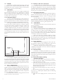
IM-201
February 2005
General Installation, Operation and Maintenance Instructions For Aerovent Products
AXICO® ANTI-STALL
(Direct Drive)
1.0 GENERAL DESCRIPTION
1.4
1.1
DEFINITIONS
A vaneaxial fan is an axial fan with a vane section
downstream of the rotor. The vane section converts the rotating component of the airflow into axial flow and pressure,
increasing the static pressure capability of the rotor.
An adjustable pitch rotor is one where the blade angle
can be changed, but only when the rotor is stationary.
A variable pitch rotor, also called controllable pitch,
is one where the blade angle can be changed while the fan is
running.
1.2
ARRANGEMENTS
Axial fans are available in two different configurations,
defined as follows:
Arrangement 4, Type 2 — The rotor is mounted
directly on the motor shaft, and the motor is upstream of the
rotor, with both rotor and motor enclosed in the fan tube.
Arrangement 4, Type 3 — The rotor is mounted
directly on the motor shaft, and the motor is upstream of the
rotor, but supported outside the fan tube.
Aerovent axial fans offer the following combinations
of these basic definitions, using the nomenclature shown:
Description
AXICO
Vaneaxial Fan
X
Adjustable Pitch
FPDA
Variable Pitch:
Electric Control
FPMC
Hand Crank Control
FPMC
Pneumatic Control
FPAC
Arrangement 4, Type 2
X
Arrangement 4, Type 3
X
1.3
APPLICATION
If the application requires that the inlet to the fan be
ducted, Arrangement 4 Type 3 cannot be used. All the other
arrangements are furnished with an inlet duct flange to which an
inlet duct or an inlet bell can be fastened.
Arrangement 4 Type 3 fans are ideally suited for plenum applications with a free inlet condition as this arrangement can permit the fan to be placed much closer to the coils
or filters upstream.
a.
b.
c.
d.
e.
f.
g.
h.
ACCESSORIES
Various accessories are available for AXICO fans.
Inlet bell and screen (standard on Arrangement 4 Type 3
fans)
Inlet cones
Vane section (standard on AXICO fans)
Discharge diffuser sections (two types)
Acoustic discharge diffuser sections
Flexible duct connections and band clamps
Gravity backdraft dampers
Vibration isolation
1.5
OPTIONS
AXICO fans may be furnished with various options to
meet job requirements:
a. Legs for floor mounting.
b. Brackets for vertical, horizontal, or angular mounting from
the floor or ceiling.
c. Electric operator or manual hand-wheel for adjustment of
AXICO FPMC when in operation, or quadrant and clamp
adjustment when the fan is turned off
d. AXICO fan operators and positioners located at other than
top dead center
1.6 NAMEPLATE NOMENCLATURE
The model number information on each fan nameplate is
explained on page 14.
2.0 INSTALLATION
2.1
RECEIVING/INSPECTION/STORAGE
Each Aerovent fan is shipped on a wooden pallet and
is covered with plastic for weather protection.
Carefully inspect the fan upon arrival for damage
incurred during shipment. Immediately report any damage to
both the factory and the carrier.
For short-term storage prior to installation, the fan
should remain covered with plastic wrap on the shipping pallet
and stored in a clean, dry location away from the elements. If
storage is to be for a period longer than 30 days, see page 15
for long-term storage instructions.
©2005 Aerovent
2.2
LIFTING
Aerovent fans should be lifted using slings. Note that
on AXICO fans the slings should be placed under the skids,
and spreader bars used as required. Under no circumstances
should the vane section be used for lifting.
2.3
MOUNTING
Depending on the type of fan support specified, the
fan can be floor mounted on legs, supported on a structural
frame or ceiling hung if clips or support brackets are included,
and again supported on the floor on a frame, or ceiling hung
if the fan is for vertical airflow.
2.3.1 Vibration Isolators
The fan is dynamically balanced to reduce vibration to
a low level. However, it is recommended that the fan be supported on vibration isolators. Isolators should be selected for
each installation in accordance with individual requirements.
The weight distribution between mounts is not equal
on Aerovent fans. Consult the factory for isolator selection
or mount loads. Isolators should be selected to support the
unequal load with equal deflection. A subbase can be used
to equally distribute the load to the isolators. Concrete inertia
pads are generally not required on Aerovent axial fans. When
mounting isolators or tie-down bolts through the base frame
of an Arrangement 4 Type 3 fan, it is recommended that you
use a beveled washer between the base frame and the nut. See
Figure 1.
Figure 1.
Beveled
Washer
2.4.1 Diffuser and Cone Connection
On AXICO fans, the standard discharge is not intended to be directly connected to the fan vane section. Support
the diffuser independently of the fan and provide a flexible
connection between the fan and the diffuser. On all Aerovent
fans, inlet cones can be directly connected and they also
become part of the load to be isolated.
2.4.2 Inlet Bell Connection
The inlet bell may be mounted in a plenum wall with a
flexible connection between the outer edge of the bell and a
hole in the partition. Provide a 2-inch to 3-inch gap to allow
for fan movement.
The inlet bell may be installed protruding into the plenum where space is limited. A metal ring should be installed
between the inlet bell and the case flange and a flexible connection installed between the ring and the plenum wall.
2.5
ELECTRICAL
All wiring should conform to local electrical codes and
the job specification.
2.5.1 Power Connection
The motor leads terminate in the conduit box. The
leads are factory connected for the voltage specified for the
job. Motor leads for wye-delta and part-winding starts are
not connected. Rigid conduit should be run from the motor
starter to the fan with a short section of flexible conduit at the
conduit box to allow for fan movement.
Wire size and motor overloads should be sized in
accordance with the fan nameplate electrical data. The conduit
box is located on the outside of the case on all ducted, direct
driven fans. If the motor is outside the fan case, connection
will be made directly to the motor.
2.5.2 Motor Rotation
Check motor rotation by jogging the motor. The rotation should be clockwise when viewed from the inlet of the
fan. Reverse any two motor leads to change rotation.
NOTE: It is important that correct motor rotation be
established on ducted fans as the rotor will not be visible after
an inlet duct is installed.
2.5.3 Electrical Data
If the fan is a variable pitch AXICO fan, it is recommended that the fan not be run until the controls are operational. The fan should be started in accordance with Section
2.5.4 and the electrical data measured and compared to motor
nameplate ratings.
2.3.2 Fan Reactions
It is essential to minimize fan movement due to starting torque and air thrust force. These forces must be resisted
to maintain duct alignment and prevent damaging the flexible
connectors. Isolators must be selected with adequate stiffness
to resist these forces. Snubbers may be required in some installations to limit the fan movement.
2.4
DUCT CONNECTIONS
All fans should be closely aligned with the ductwork. A
flexible connection should be provided between the fan and
duct to prevent structure-borne noise from being transmitted to the ductwork. Use band clamps and seal with Borden’s
Arabol, or equal, to insure mechanical security and prevent
leakage on all flexible connections.
NOTE: Provide a 1-inch to 2-inch gap between the fan
and duct to allow for fan movement.
2
2.5.4 Final Check Before Putting
Fan Into Operation
1. Check for correct supply voltage and motor overloads.
2. Insure that all loose debris is removed from fan, fan
room, plenum and/or all ducts.
3. Check that motor bolts are tight and rotor is centered in
fan case with adequate blade tip clearance all- around. See
Section 6.6 for motor bolt torque data, and Section 6.7 for
minimum blade tip clearance.
4. Hand rotate and then bump the fan starter to check rotation.
5. Start the fan and verify that the vibration is acceptable.
If the fan is a variable pitch AXICO, make the following
additional checks.
6. Check that the air supply pressure is correct (60 to 100
psig).
Aerovent IM-201
7. Set controller at a low set point for minimum pitch (3 psig
branch pressure to the positioner) for direct acting.
8. Verify once again that the vibration is acceptable.
9. Increase the set point for maximum pitch and measure
motor current. Check that full load current does not
exceed motor nameplate data. Also verify that the vibration level at full pitch is acceptable.
10. Verify that blade pitch changes smoothly throughout
the full range as the controller set point is moved. If the
AXICO fan has an electric operator, follow the same procedure except of course varying the signal input circuit to
the Honeywell electric opener.
Figure 2. Schematic of Pilot Positioner and
Direct Acting FPAC Fan
Operating
Air To
Diaphragm
(Top Port)
Valve Air
Zero
Return
Spring
3.0 AXICO FAN BLADE ADJUSTMENT
3.1
FPAC FAN
The FPAC fan has a pneumatic diaphragm incorporated in the hub to operate the blade pitch changing mechanism. Air is supplied to the diaphragm through a rotary union
connected to a valve positioner mounted n the vane section.
The positioner is mechanically connected to the diaphragm by
a flexible cable.
3.1.1 Positioner — Function
The function of the positioner is to modulate the air
pressure to the diaphragm in response to the control pressure.
By means of the mechanical feedback it can sense the blade
pitch and thus satisfy the control set point. The positioner will
provide linear response to the control pressure.
The positioner is factory set to operate in the direct acting mode. This means that a decreasing control pressure will
cause a decrease in blade pitch and less airflow.
3.1.2 General Description of How It Works
The pilot positioner is a single acting, singe-stage,
force-balance type control device. Mounted on an AXICO
fan, and cable-connected to the rotor operating mechanism, it
uses an auxiliary air supply and a feedback cam controlled by
the cable to position the rotor mechanism in accordance with
the 3-15 psig air signal from the controller.
Figure 2 is a schematic diagram of this system.
Remember that the feedback spring maintains upward pressure on the positioner arm at all times, and this keeps the
cable in tension. Since the positioner is direct acting, a 3 psig
instrument gauge pressure results in 0 psig valve gauge pressure or minimum pitch position. When the instrument gauge
indicates 15 psig, this results in maximum valve pressure and
thus maximum pitch. The tendency of the fan blades is to go
to minimum pitch, so that, when the diaphragm pressure is
reduced, the spider will move towards the rotor, pulling the
positioner arm down and compressing the feedback spring.
3.1.3 Positioner Connections
There are three 1∕4" NPT ports on the positioner. The
top port is connected to the diaphragm on the fan rotor.
The middle port should be field connected to the controller
(branch line). The bottom port should be field connected to
main air supply. Supply air should be clean and dry
instrument air. Moisture or dirt in the supply air
will cause the pilot on the positioner to malfunction after repeated exposure. The supply pressure to
the positioner should be regulated as required to achieve full
pitch. The supply pressure needed is a function of fan speed
and size.
Aerovent IM-201
Controller
Input Signal
Air (Middle
Port)
Vent
Feedback
Cam
Main Air
Supply
(Bottom
Port)
Feedback
Spring
Fan Rotor
3.1.4 Positioner Calibration and Adjustment
The positioner is factory calibrated and no further
adjustment is normally required. The calibration can be easily checked and corrected if normal fan control cannot be
achieved. The positioner must be adjusted if replaced or the
cable is removed from the lever arm.
To adjust the positioner, proceed as follows:
1. With fan off, disconnect the air line on the positioner to
the fan rotor and connect this line to a 1∕4" NPT pressure
regulator.
2. Check that the cable is in alignment with the hole where
it enters the stator vane core. If not, adjust the positioner
on the mounting bracket (not the pin in the slotted arm),
keeping the positioner horizontal with respect to the case.
3. Adjust the pressure regulator to supply full line pressure
to the fan diaphragm. Loosen the cable clamp on the
positioner arm and pull cable tight. Mark the cable where
it protrudes through the stator case. This is the maximum
pitch position. Reduce the pressure to the diaphragm to
zero and start the fan while maintaining tension on the
cable by pulling upward on the cable. The fan will now be
in the minimum pitch position.
Mark the cable again in the minimum pitch position. Turn
off the fan.
WARNING: Do not release cable tension while fan is in
operation. Wait until fan has come to a complete stop.
NOTE: The blades may not fully return to the minimum
pitch position unless fan is operating.
4. Adjust the pressure to the diaphragm to move the cable
midway between the two reference marks. Measure carefully and maintain this position. Remove the side cover
plate on the positioner. Grasp the positioner arm and move
it to align the line engraved on the cam with the centerline
of the cam roller (see Figure 2). Tighten the cable clamp.
NOTE: The positioner is now mechanically adjusted at
mid-range with the fan blade pitch mechanism at the mid
position.
3
5. Reconnect air line from the diaphragm to the positioner.
6. Proceed with the positioner calibration, as described
below:
a. Connect a 1∕4-NPT pressure regulator to the instrument
port to simulate a control pressure.
b. Turn on the supply air. Adjust the regulator to 9 psig
control pressure.
c. The mark on the cam should point to the center of the
cam follower. If not, turn spring adjusting nut to align
the mark.
d. Replace the cover plate and reconnect the control pressure line to the middle port.
e. The positioner is now adjusted and calibrated to provide
linear blade pitch control from a 3 to 15 psig control
pressure.
NOTE: It is advised that a 0-30 psi pressure gauge of
known accuracy be used during the calibration procedure.
NOTE: In the event that a positioner has to be replaced
with a new part, the pin in the slotted arm on the new
part should be placed in the identical position as on the
old one. Specifically, the slot marking should match the
distance between the marks made on the cable in item 3
of the adjustment instructions above.
3.1.5 Air Consumption
The bleed rate of the positioner is zero. Under operating conditions, an FPAC fan will use a maximum of 0.25
SCFM of supply air.
3.2
FPMC FAN
The FPMC fan is a mechanical version of the AXICO
fan. Pitch control is achieved by a mechanical linkage connected to a thrust bearing in the hub cover. This arrangement
is available in three versions:
1. FPMC with electric operator mounted on the outside of
the vane section.
2. FPMC with a manual gear/jack mounted inside the core
of the vane section, and a handwheel mounted on the side
of the vane section to adjust pitch. This version can be
adjusted while the fan is running.
3. FPMC with the same linkage as on the motor-operated
version, but the input end of the linkage is clamped in one
position on a quadrant. This version cannot be adjusted
while the fan is running.
3.2.1 FPMC, Electric Motor Operator
The 120 VAC operator is used with FPMC fans. This
operator provides position proportion control of the AXICO
mechanical blade linkage. The operators are furnished with
end limit switches which have been factory set to match minimum and maximum pitch conditions required for each fan.
The motor will rotate the output shaft through an arc of 150°,
but the switches have been set to give the necessary linkage
stroke within this 150° arc. Operating time is 60 seconds for
the full 150°, so on an AXICO fan the time will be somewhat
shorter. The motor has a 135 ohm balancing slide wire which
must also be connected to the control relay. The motor is also
equipped with a 135 ohm feedback slide wire to permit an
output signal which can be used as the input signal to a second
relay which would control a parallel fan.
3.2.1.1 Control
Since fan pitch is being used to control duct system
static pressure in the majority of cases, a pressure sensing
transducer or slide wire bridge must be used in conjunction
with a balancing relay. This relay will operate a single pole
4
double throw switch to feed power of the correct polarity
to the operator motor to achieve CW or CCW rotation of
the output shaft. If the balancing slide wire is not connected,
the motor would run until the limit switch cuts power to the
motor in that circuit direction. Not until polarity is reversed
would the motor operate, and then it would go through full
stroke in the opposite direction until the second limit switch is
opened.
By connecting the balancing slide wire circuit back
to the balancing relay, the relay is now able to compare the
requirements of the duct sensor with the actual rotation of the
operator, and the comparison will make or break the SPDT
switch, changing operator rotational direction in a stepping
manner. Thus, the system becomes proportional.
3.2.1.2 Actuator Electrical Connection
All electric connections should be in strict accordance with the job specification and local electric codes. Refer
to the current manufacturer's owner's manual for a schematic
wiring diagram.
3.2.1.3 Actuator Replacement
The actuator is factory adjusted to provide the
full range of blade pitch movement. Should the actuator be
replaced, the limit switches must be adjusted to prevent the
motor from stalling at the maximum and minimum pitch positions.
To replace the actuator proceed as follows:
1. Remove the crankarm from the motor shaft without disturbing the ball joint and pushrod location.
2. Remove wiring and mark terminal locations.
3. Remove four mounting bolts and replace actuator with
new unit.
4. Remove four screws from the end cover and remove the
cover.
5. Connect 120 VAC power to the proper terminals, according to the owner's manual, to drive motor to mid-position
of shaft rotation as indicated by wiper arm location.
6. Move pitch control lever to mid-position and install crankarm on motor shaft.
7. Drive motor counterclockwise, according to the owner's
manual, to the maximum pitch position.
8. Adjust limit switch (LS1), according to the owner's manual, to open at this position.
9. Drive motor clockwise, according to the owner's manual,
to the minimum pitch position.
10. Adjust limit switch (LS2), according to the owner's manual, to open at this position.
CAUTION: Check that the limit switches are properly
adjusted and that the actuator motor does not stall at
either of the two extreme positions.
11. Reconnect wiring, according to the owner's manual, and
replace covers.
3.2.1.4 Actuator Linkage Adjustment
Should the linkage be removed during fan disassembly, it may be adjusted as follows:
1. Position the pitch control lever and actuator motor at
mid-position per Section 3.2.1.3.
2. Install crankarm in an upward vertical position on motor
shaft.
3. Install ball joint on crank arm at the minimum radius
from shaft, which will permit the wiper arm to operate
within the length of the slide wire. It must not run off at
either end.
Aerovent IM-201
4. Install push rod and tighten ball joint.
5. Adjust limit switches per Section 3.2.1.3.
3.2.1.5 Actuator Pitch Adjustment
The maximum and minimum blade pitch is mechanically set in the rotor. The limit switches in the actuator can be
reset to reduce the range between these limits to provide different maximum and minimum airflows. This may be done as
follows:
1. Remove terminal box and/or end covers from actuator as
required.
2. Energize terminals, according to the owner's manual, with
120 VAC to drive the blades to minimum pitch.
3. Start the fan and energize the proper terminals, according to the owner's manual, to increase the pitch until the
desired maximum airflow is obtained.
4. Adjust limit switch (LS1), according to the owner's manual, to open at this position. This will stop the motor at
the new maximum pitch position.
5. Energize terminals, according to the owner's manual, to
decrease the pitch until the desired minimum airflow is
obtained.
6. Adjust limit switch (LS2), according to the owner's manual, to open at this position. The motor will stop at the
new minimum pitch position.
7. Check limit switch adjustment by driving motor through
range.
8. Replace terminal box and/or end covers as required.
3.2.2 FPMC Fan, Handwheel Version
An external handwheel on the vane section is connected to a miniature wormgear jack inside the core of the
vane section. This in turn is connected to the hub cover of
the rotor. If the handwheel is installed on the right side of
the fan, looking in the direction of airflow, counterclockwise
rotation of the wheel will increase blade pitch. If installed on
the left side, clockwise rotation will increase pitch. With this
arrangement the blade pitch can be changed while the fan is
running.
3.2.3 FPMC Fan, Quadrant
With this version of the FPMC, the external linkage to
the rotor is clamped in one position by a handwheel on a fixed
bolt. The blade forces are such that the fan must be turned off
to adjust the blade pitch. Move the lever upstream to decrease
pitch, downstream to increase it.
3.3
AXICO FPDA FAN
The FPDA fan is an adjustable pitch fan. The blade
pitch has been factory set to meet the airflow requirement of
the job specification. The blade pitch may be changed to meet
other airflow requirements. The hub fairing is marked with
degree marks at the leading edge of the fan blade The first
mark near the inlet side of the fairing is 60°. The last mark
near the center of the fairing is 25°. The intermediate marks
are in 5° increments. The marks are referenced to the center
of the leading edge of the fan blade.
3.3.1 Blade Pitch Adjustment
To set the blade pitch proceed as follows:
NOTE: An 8 mm key with a square drive adaptor fitted
to a torque wrench is required.
1. Remove the stator section access panel per steps 1
through 5 of Section 5.9 to gain access to the fan blades
on Arrangement 4 Type 2 fans. Access on other fans may
be gained by removal of the protective inlet screen if
desired.
Aerovent IM-201
2. Loosen the four M12 blade bolts until the blade is free to
rotate.
3. Rotate the blade to align the center of the leading edge with
the desired pitch mark.
CAUTION: Do not exceed 55° blade pitch without consulting factory.
4. Alternately tighten opposite blade bolts to 40 ft-lb.
CAUTION: It is important that the bolts are torqued to the
specified value. Do not hand-tighten the bolts.
5. Repeat Steps 2 through 4 for all blades.
6. Replace stator section access panel or inlet screen.
CAUTION: The motor current should be checked not to
exceed the nameplate rating when blade pitch has been
increased.
4.0 INSTRUMENTATION (PITCH
CONTROL) AXICO FANS
4.1
GENERAL
Various parameters such as pressure, temperature, gas
concentration, relative humidity, or velocity can be measured
to provide the required system airflow. The sensor is connected to a controller which provides an electrical or pneumatic
control signal to the fan. The fan pitch is modulated to meet
the system airflow set point requirement.
4.2
FPAC FAN
The FPAC AXICO fan is factory adjusted to go from
minimum to maximum pitch with a 3 to 15 psig pneumatic
control signal. Two-position or multi-position pitch settings
may be obtained with intermediate control pressures. The
blade pitch may also be manually controlled by supplying the
control pressure from a pressure regulator.
4.3
FPMC FAN
The FPMC fan actuator is adjusted at the factory to go
from minimum and maximum pitch with limit switches at the
ends of the stroke. The limit switch settings may be changed
to reduce the range of blade pitch for two-position step
control from contact closure. See Figure 3 for typical wiring
diagram.
4.4
PARALLEL FAN OPERATION
When two or more fans are installed to operate in parallel, two problems are commonly experienced.
1. When less than all the fans are in operation, air circulates
backwards through the fan that is shut down, causing it to
freewheel backwards. This can be very damaging to the
motor when the fan is restarted.
2. When all fans are running together, they may not be completely stable.
SOLUTION: The signal to all fans must be a common
signal, and it should be a heavily damped signal so the changes
of blade angle occur very slowly. Also the fans must have their
positioners calibrated so that all positioner arms are at the
same angle for a given control pressure. A second check can
be made to insure that motor amps match within 5% at a given
signal pressure.
NOTE: STARTING A FAN WHILE THE ROTOR
ASSEMBLY IS WINDMILLING BACKWARDS VOIDS
ALL MOTOR AND FAN WARRANTIES.
5
5.0 MAINTENANCE
5.3
5.1
GENERAL
Aerovent fans are a quality product designed and
manufactured for minimum maintenance and long operating
life. They should provide years of trouble-free service if the
following maintenance procedures are followed.
Aerovent fans are balanced at the factory to the following standards. NEMA has set standards for motor balance
which are also shown. Bearing life and lubrication requirements are based on the NEMA standard. The more stringent
Aerovent standards allow for normal build-up of dirt on
rotors; use, evaporation and/or shifting of lubricants; and
normal wear. If a fan appears to be out of balance, it is wise
to clean and grease before attempting to balance as this may
resolve the situation in the simplest manner.
In the event that the fan does not require dynamic balancing, balancing weights should be added as described in this
text.
Balance weights should be located only between the
blade hole openings and on the front and rear of the hub fairing. See Figure 4.
Balance weights should not exceed the weight (in
grams) listed in Figure 4.
RPM
3600
1800
1200
900
0.6
0.8
1.2
1.6
AEROVENT
STANDARD
Mils Peak/Peak
Mils Peak/Peak
Mils Peak/Peak
Mils Peak/Peak
SHUTDOWN
2.20
4.40
6.70
8.90
MILS
ALARM
1.42
2.84
4.26
5.60
5.2
MOTOR LUBRICATION
Motor bearings do not require initial lubrication unless
the fan has been in storage over six months. If this is the case,
the motor should be lubricated initially.
Lubricate motor bearings with grease gun at the following intervals and numbers of strokes:
HORSEPOWER
PERIOD
5 to 71⁄2
10 to 40
50 to 150
12 Month
6 to 12 Month
6 Month
STROKES
(SEE NOTE)
1
3
3
NOTE: Normal amount of grease delivered by a hand cartridge type grease gun.
Use only the following lubricants or their equal:
Chevron SR-2
A.F. No.2
Precision No. 2
Alvania No. 2
Starfak H, M and No. 2
Mobilith AW2
Mobil Grease #77
The grease fittings must be clean to prevent contamination.
The fittings are located as follows:
TYPE FAN
LOCATION
Arrangement 4, Type 2
Fan case adjacent to conduit box
Arrangement 4, Type 3
End of motor base
CAUTION: Do not over lubricate bearings or use a grease
other than specified.
6
AXICO FAN LUBRICATION
5.3.1 Rotor
Rotor lubrication is described in Section 5.6 under
Routine Maintenance.
5.3.2 AXICO FPMC Lubrication
In addition to the above in Section 5.3.1, all FPMC
rotors have a thrust bearing in the hub cover. The grease lead
to this bearing is on the outside of the vane section. Grease
as per Section 5.2 should be applied, one stroke once a month
of fan usage.
The FPMC unit with handwheel adjustment has a
grease fitting on the jack inside the vane section in addition
to the thrust bearing. Unless the pitch is changed frequently,
there is no reason to lubricate this more often than as part of
the two-year maintenance procedure.
The FPMC unit with external electric operator requires
lubrication with SAE 30 motor oil at the pivot joints on the
linkage every six months. The actuator requires no lubrication.
5.4
AIR LEAKS ON AXICO FPAC FANS
If, during the monthly check, an AXICO FPAC fan is
found to be acting erratically, and if the problem is not in the
external control (indicated by a constant varying 3 to 15 psig
input signal), then check for air leaks.
Listen with your ear close to the positioner. If there
is an erratic sound of air escaping when the fan is at maximum pitch, replace the pilot on the positioner (part number
F10046301).
If the pressure to the diaphragm will not hold at the
same level as main air pressure when the control pressure is
15 psig, inspect for an air leak between the positioner and
the rotor. Shut the fan off, but maintain pressure to the diaphragm, and proceed as in Section 5.7 to remove the access
door to the vane section. Check the air line, the diaphragm
cover bolts, and the rotary union for leaks (turn fan by hand
to detect rotary union leaks).
If the rotary union is removed or replaced with a new
one, use Loctite Stainless Steel PST on the threads going into
the diaphragm cover.
5.5
SIX-MONTH INSPECTION
AND MAINTENANCE
The motor bearings may require lubrication depending
on motor size per Section 5.2.
The FPMC fan linkage should be lubricated per Section
5.3.2.
5.6
ANNUAL AND TWO-YEAR MAINTENANCE
A minor inspection of the AXICO rotor is required
every two years, but recommended each year for continuous
duty fans or fans operating with dirty or contaminated air.
Remove the access panel of the vane section as described in
Section 5.7 and inspect the blade links to be sure the spherical
bearings are not binding, and apply an aerosol lubricant such
as CRC or WD-40.
Grease blade shaft bearings by applying grease through
the fitting in the bearing housing until excess grease comes
past the seal. Wipe away excess.
Aerovent IM-201
Figure 4.
6.0 ROTOR REPAIR & REMOVAL
(Not Required For Maintenance)
6.1
FPAC Fan
1. Remove the access section as described in Section
5.7.
2. Remove the air line from the rotary union.
3. Remove the two screws holding the flexible cable
bar to the rotary union.
4. Remove the 1∕2" nuts and washers around the vane
section flange while supporting the vane section.
5. Slide the vane section off the fan case and remove
it sideways. The rotor is now removable.
This operation should take no more than 1 to
2 hours per fan.
Flow Section
A
B
Hub
HUB
500
630
800
MAX. WT. (g)
A
B
70
150
70
150
70
150
The balancing weights permitted at Position
A are located according to Figure 4 below.
Maximum permitted weight for each place
according to the tables above. Note that
only one hole may be drilled between the
holes for the blades.
FPMC Fans
1. Remove the clevis pin in the vane section core.
2. Remove the drive linkage to the operator, if used.
3. Remove the clevis pin between the bar linkage and
the fixed bracket on the fan. The bar can remain in
the vane section.
4. Proceed with steps 4 and 5 as described above for
FPAC vane section removal.
Holes For Blades
Balancing Weights
Note: If the spider is the old style that uses grease,
apply 4 to 5 strokes of a grease gun to the grease fitting behind
the spider. This will lubricate the spider hub sliding joint.
Before closing up the access panel, operate the control to cycle
the pitch several times to insure all parts move smoothly.
Every two years it is recommended that you replace
the rotary union with a new one. The longevity of the union
is dependent on the quality of the compressed air supply, and
it is a simple precaution to replace it while it is accessible.
CAUTION: Use Loctite 242 on the two screws holding the flexible cable bar to the rotary union at any time these
screws are removed and replaced.
This operation should take no more than 1 to
2 hours per fan.
5.7
VANE SECTION ACCESS
Both the FPAC and FPMC fans have removable access
sections in the vane section. This provides enough visibility
and working space for all maintenance short of removing the
fan rotor from the motor shaft.
To remove the access sections, proceed as follows:
1. Remove the flexible duct connection between the vane section and the diffuser or duct.
2. Remove the 1∕4" bolts at the side of the vane section and
remove the 1∕2" washers and bolts at the flange of the
access panel.
3. Remove the panel exposing the internal stator vanes.
4. Remove the 1∕4" bolts from the side of the inner case.
5. Remove the inner core access panel with the three vanes
welded to it. The interior of the vane section and the operating mechanism of the rotor is now accessible.
ACCESS TO ROTOR
6.2
ROTOR REMOVAL
(Not Required For Maintenance)
If the rotor is to be removed from the motor shaft,
proceed as follows:
FPAC Rotor
Refer to Figure 6 for item identification.
1. Measure and record the distanced from the end of
the stud (10) to the stud bar (26).
CAUTION: This distance must be maintained at
assembly to set the maximum pitch.
2. Remove the nuts (21), stud bar, and springs (11)
from the studs.
3. Remove the bolts (15), diaphragm cover (1) and
diaphragm (8) from the spider (2).
CAUTION: Mark the position of the diaphragm cover
with respect to the spider so that it can be installed correctly and rotor balance be maintained.
4. The motor shaft bolt (32) is now visible. After
removing it, the rotor can be pulled off the motor
shaft. Two threaded holes are provided in the face
of the hub to anchor a puller bar.
FPMC Rotor
Refer to page 13 for item identification.
1. Measure and record the distance from the end of
the stud (10) to the first locknut (21).
CAUTION: This distance must be maintained at
assembly to set the maximum pitch.
2. Remove the nuts (21) from the studs.
3. Remove the bolts (15) around the hub cover (59)
and take the cover off.
CAUTION: Mark the position of the diaphragm cover
with respect to the spider so that it can be installed correctly and rotor balance be maintained.
Aerovent IM-201
7
4. The motor shaft bolt (62) is now visible. After
removing it, the rotor can be pulled off the motor
shaft. Two threaded holes are provided in the face
of the hub to anchor a puller bar.
6.3
ROTOR DISASSEMBLY & INSPECTION
(Not Required For Maintenance)
If the rotor is to be serviced on site, proceed as fol-
lows.
1. Remove the diaphragm cover and diaphragm (FPAC) or
hub cover (FPMC) as per Section 6.2.
2. Remove the bolts retaining the links to the spider arms.
Mark the spider arms and blade bearing housings to
insure proper reassembly.
3. Slide the spider off the hub, using a continuous twisting
motion.
4. Remove the four socket head screws from each blade,
using an 8 mm hex key. Remove the blades from the bearing housings. Remove the spring, plunger, air seal, and
grease gasket from each blade position.
CAUTION: Mark all parts to insure they will be reinstalled in the exact location from which they were
removed. Also, all parts must be thoroughly cleaned, and
kept clean until everything is reassembled.
5. Remove the blade shafts, blade bearing, and bearing housing from the hub. The blade shafts have been assembled,
using Loctite 242 thread sealant, so it may be necessary
to apply heat to break loose the thread; do not exceed
250°F.
6. Clean the blade bearings with solvent or kerosene.
2.
3.
4.
CAUTION: Do not mix races and rollers as the bearings
should be maintained as a set.
After the bearings are clean, inspect the contact surfaces
for signs of spalling, pitting, cracks, brinelling, or smearing. Replace all bearings from spare parts if there is evidence of wear. If the bearings are not to be immediately
used, coat with oil and wrap in grease paper.
7. Clean the threads on the shafts with a wire brush to
remove the sealant.
8. Clean all remaining parts with solvent to remove dirt and
grease.
9. Inspect the spider bore and hub bearing surfaces for galling. Lightly dress out any surface defects with fine emery
paper and clean with solvent.
DO NOT remove the hub fairing (6) from the hub
as it will affect the rotor balance.
10. FPMC Thrust Bearing
a. Remove the three bolts holding the grease re-tainer
plate inside the hub cover. Remove the bearing nut and
lock washer from the shaft. Then withdraw the shaft
and attached clevis from the bearing.
b. Check the thrust bearing for wear. If loose or noisy,
press out the bearing and replace with a new part from
spares. Apply Loctite 271 between bearing O.D. and
cover.
6.4
ROTOR ASSEMBLY
To assemble the rotor proceed as follows:
NOTE: An 8 mm hex key with a square drive adaptor
fitted to a torque wrench is required.
1. Grease the blade bearings with Chevron SRI-2 or equal and
assemble on shaft with bearing retainer.
NOTE: It is important to maintain clean conditions when
lubricating bearings.
8
5
6.
7.
8.
All parts requiring Loctite must be clean and free of oil
and dirt or Loctite will not cure completely. To clean, use a
non-lubricating cleaner such as trichlorothane.
Apply Loctite grade T. Primer to blade shaft threads and
hub threads. Allow to air dry 5 minutes. Apply Loctite 242
to the threads of the shaft. Screw into the hub until the bolt
bottoms firmly on the shoulder. Torque to 60 ft-lbs.
Assemble blade, spring, plunger, plastic washer (24) and
new grease gasket (30) to bearing retainer. The proper orientation is as follows when looking at the open end of the
rotor.
a. Position blade into fairing with the concave surface
facing the mechanic and the longer trailing edge of the
blade to the right.
b. Position bearing retainer with counterbalance lug facing
the mechanic and link lug to the right at about a 45degree angle to the blade.
c. The washer fits between blade and bearing retainer
inside the fairing.
d. The spring, plunger, and gasket fit between the blade
and shaft. Tighten the three 12M x 70 bolts to 70 ft-lbs
with the 8 mm hex key and torque wrench and the 12M
x 35 bolts to 60 ft-lbs.
Clean the spider, teflon insert, and hub with a solvent
to remove any dirt and grease. Carefully inspect the hub
and spider bearing surfaces for signs of galling. Lightly
dress out any surface defects with fine emery cloth and
thoroughly clean with solvent. Inspect the teflon insert for
excessive wear. Replace insert if needed. Apply a thin layer
of lithium base grease such as Chevron SRI-2, or equal, to
the sliding cylindrical surfaces.
NOTE: If your spider does not have the teflon insert, fill
the annular cavity in the spider bore with grease.
Replace the spider on the hub using the same twisting
motion to prevent jamming. Check that the spider slides
freely on the hub. If not, repeat Step 4. Position the spider
as marked in Step 2 of Section 6.3.
If the link bearings show any perceptible play or are frozen, replace all the links with new parts from spares. Use a
torque wrench to tighten the bolts to 25 ft-lbs. Check that
the mechanism operates freely as the spider is moved in
and out. See note on page 11.
FPAC Only (Refer to Section 6.5)
a. Replace the diaphragm with a new part from spares.
Using a torque wrench, progressively tighten opposite
bolts to 25 ft-lbs.
NOTE: The crown in the diaphragm fits inside the diaphragm cover.
b. Replace the rotary union (33) with a new part from
spares. Clean and prime the threads with Loctite grade
T primer, allow to air dry five minutes, and apply Loctite
stainless steel PST. Tighten until firmly seated on shoulder.
c. Replace the springs, stud bar, and nuts on the studs
maintaining the position recorded in Step 1 of Section
6.2. Tighten the jamb nuts to 24 ft-lbs.
FPMC Only (Refer to Section 6.5)
a. Replace the thrust bearing if it has been removed after
packing it with Chevron SRI-2. Replace the bearing
shaft, lock washer, and bearing nut, and pack the cavity
with grease. Replace the spacer, grease retainer plate,
and the three bolts.
b. Replace the hub cover in the position marked in Step 3
of Section 6.3. Tighten the bolts to 25 ft-lbs.
Aerovent IM-201
c. Replace the nuts on the studs, maintaining the position
recorded when they were removed. Tighten each jamb
nut to 24 ft-lbs.
6.5
ROTOR INSTALLATION
If the rotor has been removed from the shaft, obviously it must be put back in place prior to attaching the diaphragm
cover to hub cover as described above. To install the rotor on
the shaft, proceed as follows:
1. Clean fan shaft with solvent and apply a film of grease.
Locate key in keyway.
2. Slide rotor on fan shaft.
NOTE: It may be necessary to use a bar and a 1∕2"-13 UNC
stud threaded into the motor shaft with a nut to pull the
rotor on the shaft.
3. Clean bolt and shaft threads and prime with Loctite grade
T primer. Blow out internal threads with air and allow to
air dry 5 minutes. Apply Loctite 242 to threads.
4. Install washer and bolt and torque to 50 ft-lbs for 1∕2" bolt;
15 ft-lbs for 3∕8" bolt.
5. Proceed with remainder of assembly depending on fan
type per Section 6.4.
6.6
MOTOR BOLT TORQUE
Motor bolts should be torqued to the following specifications. Remember that it is not possible to check a torqued
bolt unless it is loosened first, as torque must be applied evenly
until the desired torque is reached. To tighten further after
a given torque value has been reached requires much more
torque to get the nut started than will be required to keep
tightening it, so the desired final torque must be reached in
one movement. All bolts are grade 5.
BOLT SIZE
5
⁄16-18
3
⁄16-16
1
⁄2-13
5
⁄8-11
3
⁄4-10
7
⁄8-9
TORQUE (FT-LBS)
13
27.5
75
150
240
380
6.7
MINIMUM BLADE TIP CLEARANCE
The following dimension is the minimum clearance
between the tip of any blade and the fan case.
FAN SIZE
071
080
090
100
112
125
140
160
180
200
MIN. TIP
CLEARANCE (IN.)
.030
.030
.034
.038
.043
.049
.055
.063
.072
.080
6.8
SETTING MAXIMUM PITCH ON FPAC
& FPMC FANS
If it should become necessary to adjust the maximum
blade pitch on thee fans, proceed as follows:
1. Remove vane access section as per Section 5.7.
2. Release the two lock nuts on each stud (10) to allow a
change in their position.
a. Set a protractor at the desired blade angle, 45°-47°, etc.
b. Bring fan to maximum pitch. Have the nuts on the studs
at same distance to start (item 21, near hub on Figure 6
in the AXICO instruction manual).
c. Check angle by placing the blade of the protractor
(scale) across the root (base) of the blade. When the
proper angle is found, the base of the protractor should
be parallel to the edge of the fairing. See Figure 5.
d. Adjust by turning stop nut (#21). Be sure that both
springs are compressed solid at the same time or the
spider will hang up on the hub.
NOTE: The fairing is scribed with a line that represents the
maximum blade angle that was set at the factory. This mark
can be used as a reference to check the angle. Factory blade
angle is indicated on nameplate.
CAUTION: Do not set maximum pitch stops at a blade angle
higher than 55°.
6. Tighten each locking nut.
7. Reassemble the vane access section.
6.9
MINIMUM PITCH SETTING
Aerovent AXICO fans may have minimum pitch setting accomplished by use of two extended bolts in the diaphragm cover. This may be used to prevent the flow of any
system from going below a certain specified minimum.
Size 125 and larger have minimum pitch stops as standard set, if not otherwise specified, to 0 flow. Consult factory
for specific details on specific fans.
Figure 5
Protractor Blade Scale
Base of Blade
Airflow
Rotation
=
=
Fairing Edge
Protractor Base
Aerovent IM-201
9
7.0 RECOMMENDED SPARE PARTS
7.1
GENERAL
Spare parts may be ordered either from your Aerovent
representative or directly from the factory. Prices will be
quoted at time of order. Delivery can generally be made from
stock. To order spare parts, specify:
1. Fan model number
2. Fan serial number
3. Part description
4. Part number
5. Quantity required
The fan model and serial number is on the fan nameplate.
7.2
FPAC SPARE PARTS
It is recommended that the following spare parts be
stocked to service FPAC fans:
Part Description
Part No.
Qty. Req’d
Positioner (Pilot Ass’y)
F10046301
1
Rotary Union
F10016701
1
Cable Assembly
F20034902
1
10
7.3
FPMC SPARE PARTS
It is recommended that the following spare parts be
stocked to service FPMC fans:
Part Description
Part No.
Qty. Req’d
Electric Actuator Input Signal:
4-20MA
F10103502
1
120 VAC
F100165
1
7.4
TOOLS AND MATERIALS
Special tools and materials are available from the factory to facilitate maintenance and repair of Aerovent fans.
These may be ordered by part description, part number, and
quantity required.
Part Description
Part No.
Qty. Req’d
Loctite Grade T Primer
F10024401
6 oz. aerosol
Loctite 242
F10024402
100cc bottle
Loctite Stainless Steel PST
F10024406
8.46 oz. tube
Gray Touch-up Paint
P4332028
16 oz. aerosol
F10024701
1
Tool, 8 mm hex x 3∕8
square adaptor for
AXICO blade shaft
Aerovent IM-201
FPAC-FPMC ROTOR PARTS
*Same Part for FPAC-FPMC
Part
Size 050 Hub
Size 063 Hub
1. DIAPHRAGM COVER
F300606
F300606
(FPAC ONLY)
2. SPIDER W/TEFLON INSERT
F301457
F301458
*5. HUB
F400811
F400811
*6. HUB FAIRING
F300609
F300603
*7. SHAFT, BLADE
F20132901
F20132902
8. DIAPHRAGM, FPAC
F200354
F200354
3. BLADE BEARING HOUSING
FPAC & FPMC F30147701
*4. BLADE
SANDCAST
F100461 (FAN MODELS 160, 180 & 200 ONLY)
DIE CAST
F101062 (FAN MODELS 080 THRU 140 ONLY)
9. PLUNGER
10. STUD — 050/063
080
11. SPRING, FPAC
12. LINK, SILVER
LINK, GOLD
13. SOC HD C’SK SCR
14. HEX HD SCR
15. HEX HD SCR
16. HEX HD SCR
17. HEX HD SCR
19. LOCK WASHER
20. HEX NUT
21. HEX NUT
22. BEARING, BLADE
23. SPRING, BLADE
24. AIR SEAL
26. PLATE — 050/063
080
27. SOC HD C’SK SCR
F200355
F20035601
F20035605
F10049802
F200357
F200949
F10022201
F10022203
F10022240
F10022239
F10022240
F10022213
F10022209
F10022210
F100201
F10020001
F200350
F300630
F201018
F10022216
28.
30.
31.
32.
33.
34.
35.
36.
76.
77.
78.
79.
80.
81.
82.
83.
NUT
GASKET
GREASE FITTING
ROTOR BOLT
ROTARY UNION
WASHER, HUB
050/063
080
SNAP RING
THRUST WASHER
GREASE SEAL
WIRE RING
O-RING
CABLE ASSEMBLY
PAN HEAD SCREW
HOSE CLAMP
TEFLON SLEEVE
050/063
080
OILITE BUSHING
Size 080 Hub
F301121
F301120
F400806
F401335
F20132901
F200387
F10022210
F200802
F10052303
F100334
F10016701
F20038501
F20038502
F100321
F200393
F100812
F100813
F10089801
F20034902
F10054301
F10051901
F201463
F201486
F101058
NOTES: 1. IF BOLTS #16 AND/OR #17 ON LINK MOUNT ONLY ARE REMOVED,
REPLACE WITH NEW BOLTS.
DO NOT REUSE THESE ITEMS:
BOLT #16 — PART NO. F10022239
BOLT #17 — PART NO. F10022240
2. GOLD BLADE LINK IS TO BE USED ON ALL FANS THROUGH SIZE 112.
SILVER BLADE LINK IS TO BE USED ON ALL FANS OF SIZE 125 AND
LARGER.
Aerovent IM-201
11
AXICO® FPAC IMPELLER PARTS
1.
2.
3.
4.
5.
6.
7.
8.
9.
10.
11.
12.
13.
14.
15.
16.
17.
19.
20.
21.
22.
23.
24.
26.
27.
28.
30.
31.
32.
33.
34.
35.
36.
76.
77.
78.
79.
80.
81.
82.
83.
DIAPHRAGM COVER
SPIDER
BEARING HOUSING
BLADE
HUB
HUB FAIRING
SHAFT BLADE
DIAPHRAGM
PLUNGER
STUD
SPRING
LINK
SOC HD SCR
HEX HD SCR
HEX HD SCR
HEX HD SCR
HEX HD SCR
LOCK WASHER
HEX NUT
HEX NUT
BLADE BEARING
SPRING
AIR SEAL
PLATE
SOC HD C’SK SCR
NUT
GASKET
GREASE FITTING
ROTOR BOLT
ROTORY UNION
HUB WASHER
SNAP RING
THRUST WASHER
GREASE SEAL
WIRE SEAL
O-RING
CABLE ASS’Y
PAN HD SCR
HOSE CLAMP
TEFLON SLEEVE
OILITE BUSHING
DWG.: 101236
12
Aerovent IM-201
AXICO® FPMC IMPELLER MODIFICATIONS
FPMC WITH BAR
59 COVER, 5 OR 6 HUB
COVER, 8 HUB
61 WASHER
62 BOLT
63 BEARING HOLDER
64 ACTUATOR LINK
66 GREASE
68 BOLT
69 NUT
70 WASHER
71 BOLT
72 NUT
73 WASHER
74 FITTING, GREASE
F301407
F301408
BAR
JACTUATOR FPMC
46
47
48
49
50
51
52
53
54
PIN
COTTER PIN
CLEVIS
JACTUATOR
BOLT 1⁄4-20 x 1.25
NUT 1⁄4-20
WASHER 1⁄2
LOCKWASHER 1⁄4
BAR
F1004306
F10031508
F100653
F10032310
F10032403
F10044603
F10044703
F201092
AXICO® FPDA IMPELLER PARTS
1. BLADE RETAINER
P/N F201328
2. BLADE
3. HUB
4. HEX HEAD SCREW
5. LOCK WASHER
Aerovent IM-201
6. FAIRING
7. AIR SEAL
8. BLADE SHAFT
IF 050 OR 080 HUB: P/N F20132701
IF 063 HUB: P/N F20132702
9. BLADE BOLT: P/N F10022241
13
NEW MODEL NUMBER DESIGNATION
AXICO® FANS
F __ __ __ - __ - __ __ __ - __ - __ __ - __ __ __ __ - __ __ __
AXICO® = PAC
= PMC
= PDA
ARR. 4 TYPE 2 =
2 = HORIZONTAL FLOOR LEG
4 = HORIZONTAL CEILING CLIP
6 = VERTICAL CLIP
ARR. 4 TYPE 3
3 = FLOOR MOUNT
FAN SIZE (cm) =
080
090
100
112
125
140
160
180
200
HUB SIZE
5
6
8
=
= 50.0 cm Dia.
= 63.0 cm Dia.
= 80.0 cm Dia.
BLADE COUNT =
8 = IF 5 OR 6 HUB
10 = IF 8 HUB
MOTOR RPM =
MOTOR HP =
NOTES:
1. Motor frame size must be specified in the body of the order and will no longer
be indicated within the model number.
2. Blade pitch must be indicated in the body of the order.
14
Aerovent IM-201
8.1
8.2
8.3
8.4
8.5
8.6
8.0 INSTRUCTIONS FOR LONG TERM STORAGE
If a fan is not installed immediately upon receipt, it is the responsibility
of the purchaser/user to see to it that proper procedures are followed in
order to minimize deterioration which may result from idle storage.
Fan equipment should be stored indoors or in a well sheltered location.
The storage area must be clean and dry, well above any maximum anticipated water level. The equipment should be left crated/skidded, and not
stacked over or under other equipment. Unpainted machined parts should
be given a protective coating of Sprayon #322 or equal; this coating
should be renewed periodically per the manufacturer’s instructions. For
fans equipped with vane sections, the core end cover should be removed
to gain adequate access to the interior and reach the impeller hub. These
interior areas require the same rust inhibitor application and renewal as
given above. The cover should be replaced for storage, but each may
be fastened with a minimum of assembly hardware to facilitate access.
Remaining fastener hardware should be bagged and tagged, and attached
to the fan to prevent loss of these items. (It is recommended that the
fan be tagged indicating that all fasteners must be replaced before operation.)
Each impeller blade should be numbered in sequence with a felt-tipped
marker. The blade marked No. 1 should be rotated to top center. The
blade number and date should be recorded in a log book which is to
be stored in a protective pouch attached to the fan. During storage, the
fan impeller should be rotated by hand at least 10 revolutions every 30
days to circulate the lubricant in the bearings in the motor. After the tenth
revolution, stop with a blade at top center which is not the same one as
is listed for the previous date in the log book.
If the fan motor is equipped with internal heaters, the heaters must be
energized throughout the storage period to prevent condensation which
might damage bearings or electrical components. For motors not equipped
with internal heaters, the motor should be enclosed in heavy-duty polyethylene, wrapped as tightly as possible.
Enclose bags of dessicant (such as Silicagel) with the motor to minimize
moisture problems. Check the dessicant regularly and replace it periodically as dictated by climate requirements. In addition, it is strongly suggested that the motor manufacturer be contacted for specific long term
storage instructions.
The bearings in the fan motor or on the fan shaft should require only
minimum lubrication during storage. Follow lubrication instructions in the
instruction manual enclosed with the fan.
After an extended period of storage, it is advisable to have the fan motor
thoroughly checked before the fan is installed. Motor bearings, lubricant
and electrical condition should be given special consideration. Reassemble
cover to fan and follow AXIAD instruction manual for installation and startup.
Aerovent IM-201
15
SERVICE
ORGANIZATIONS
Air Performance Service, Inc.
10625 Control Place
Dallas, TX 75238
Phone: (972) 387-3334
Fax: (972) 991-2902
LONG Mechanical Solutions
5325 South Polaris Ave., Ste. 500
Las Vegas, NV 89118
Phone: (702) 871-4888
Fax: (702) 871-8136
DMR Associates, Inc.
16830 Oakmont Avenue
Gaithersburg, MD 20877
Phone: (301) 948-0020
Fax: (301) 948-7853
LONG Mechanical Solutions
674 Salt Creek Hwy
Casper, WY 82601
Phone: (307) 265-5997
Fax: (307) 265-0120
E/C Vibration & Balancing Service Ltd.
726 Lunt Avenue
Schaumburg, IL 60193
Phone: (847) 352-7076
Fax: (847) 351-8231
Longo Industries
1 Harry Shupe Blvd.
Wharton, NJ 07885
Phone: (973) 537-0400
Fax: (973) 537-0420
D.S. Hanback Company
14635 North First Avenue
Phoenix, AZ 85023
Phone: (602) 548-8101
Fax: (602) 548-8185
Hahn-Mason Air Systems, Inc.
P.O. Box 10465
Raleigh, NC 27605-0465
Phone: (919) 834-9230
Fax: (919) 831-9714
LONG Mechanical Solutions
1795 West Yale Avenue
Englewood, CO 80110
Phone: (303) 975-2100
Fax: (303) 936-2755
LONG Mechanical Solutions
80 West Louise Avenue
Salt Lake City, UT 84115
Phone: (801) 487-0808
Fax: (801) 485-4230
Fred Williams, Inc.
20 Scanlon Drive
Randolph, MA 02368
Phone: (781) 961-1500
Fax: (781) 961-1879
IBT, Inc.
9400 W. 55th Street
Shawnee Mission, KS 66201-1382
Phone: (913) 677-3151
Fax: (913) 677-3752
Facilities Inc.
1610 Red Soils Court
Oregon City, OR 97045
Phone: (503) 723-4568
Fax: (503) 723-4571
®
1MPP02/05
TM