1
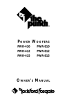
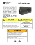
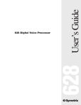
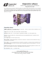
OmniAire 18000
Omnitec Design, Manufacturing Air Purification
Equipment Since 1988
For your larger projects the OmniAire 18000 is the right tool. The modular design of this system allows for ease of transport
and many different configuration choices. The 3 HEPA filter cabinets are connected to the blower with 18" flex ducts which
allows them to be placed up to 25 feet away from the blower, and also allows them to be placed in different areas if necessary. The design of the HEPA filter cabinets allows for the use of bag filters or carbon vapor trap filters in place of the
HEPA filters if required.
OmniAire 18000
Airflow - 18000 cfm, 2 - 22" vaneaxial fans with 7.5 hp motors. Airflows are based on blower manufacturer curves.
Different HEPA filters may cause the flow to vary.
Weight - Blower Unit - 900 lbs., Filter Cabinet 200 lbs. with filters installed.
Dimensions - Blower Unit - 32" wide 72" high 43" long; HEPA Filter Module - 26" wide 80" high 28" long.
Filtration - Primary/Secondary Filter - Dual-ply Dustlok polyester pad, Standard HEPA Filter - Wood Frame 99.97%
Efficiency .3 micron.
Power Requirement - 230V/60 Hz 3 phase 45 amp.
Blower Cabinet - Aircraft grade aluminum, closed end rivet construction. All seams are silicone sealed before riveting. 4
4" casters for ease of movement.
Filter Cabinets - Powder coated galvanized steel, closed end rivet construction. All seams are silicone sealed before riveting. 4 3" casters for ease of movement. Each filter cabinet is individually monitored for filter loading by a 0"-5" WC differential pressure gauge.
Controls -Dual motor starter boxes with 32A disconnects w/lockout feature. Start and Stop pushbutton switches for each
blower. Power On Indicator for each blower. Individual hour meters for each blower.
Hose Connections - Outlet - 2 - 24" diameter rings.
www.omnitecdesign.com
2125 196th Street SW, Suite 115, Lynnwood, WA 98036
phone 425-774-3257 fax 425-774-4983
1
OmniAire 18000 Air Filtration System
IMPORTANT INSTRUCTIONS
Read all the instructions before using this machine.
CAUTION
•
•
•
•
•
•
Connect ONLY to outlets that are properly grounded.
Do not operate blower with damaged cord or plug or after it has been damaged in any manner. .
Place cord out of the path of foot and equipment traffic to avoid trip hazard.
To shut down the blower unit, turn both motors off and then unplug the cord.
Do not locate blower cabinet outdoors, use only in DRY location.
The motor and the protection circuit has arcing or sparking parts inside. Avoid operating in an environment
with flammable liquids, gas, or paint.
• Do not use to exhaust combustible or explosive gases or operate in hazardous atmosphere.
• Do not insert or allow foreign objects to enter intake or outlet openings as this may cause electrical shock or
fire and will damage the blower.
• DO NOT BLOCK OFF blower cabinet INTAKES or operate HEPA filter cabinets above 4.0” WC of vacuum
to prevent possible damage to the blower cabinet, HEPA filters and the HEPA cabinets.
All three blower intake connections to HEPA Cabinets must have hoses rated to operate at 10” WC vacuum or
more.
• DO NOT operate the system without all 9 HEPA filters securely in place.
• Always unplug unit when not in use.
• Use the OA18000 only as prescribed, any other use may cause fire, shock or injury to persons.
SAVE THESE INSTRUCTIONS
WARNING
“GROUNDING INSTRUCTIONS - This appliance must be grounded. In the event of a malfunction or breakdown, grounding
will reduce the risk of electric shock by providing a path of least resistance for electric current. This appliance is equipped
with a cord having an appliance-grounding conductor and a grounding plug. The plug must be plugged into an appropriate
outlet that is installed and grounded in accordance with all local codes and ordinances.”
“WARNING - Improper connection of the appliance-grounding conductor can result in a risk of electric shock. Check with a
qualified electrician or service representative if you are in doubt whether the appliance is properly grounded. Do not modify
the plug provided with the appliance; if it will not fit the outlet, have a proper outlet installed by a qualified technician.”
AVERTISSEMENT:
"INSTRUCTIONS DE MISE À LA TERRE - Cet appareil doit être mis à la terre. En cas de défaillance ou de panne, la terre
réduira le risque de choc électrique en fournissant un chemin de moindre résistance au courant électrique. Cet appareil est
équipé d'un cordon comportant un conducteur de l 'appareil à la terre et une prise de mise à la terre. La prise de mise à la terre
doit être branchée dans une prise électrique appropriée, installée et mise à la terre conformément aux codes et règlements
locaux."
"ATTENTION - Une connexion incorrecte du conducteur de l 'appareil à la terre peut entraîner un risque de choc électrique.
Vérifier avec un électricien qualifié ou un représentant de service si vous êtes dans le doute si l'appareil est correctement mise
à la terre. Ne pas modifier la fiche fournie avec l'appareil;. si elle n'entre pas dans la prise, faites installer une prise adéquate
par un technicien qualifié."
2
LIST OF COMPONENTS
OmniAire 18000......... OA18000
2 - 22” Aerovent Vaneaxial Blowers
2 - Motor Starter Enclosures with
• Cutler-Hammer Contactor
• Cutler-Hammer Overload Relay
• Sprecher-Schuh Disconnect Switch
9 - HEPA filters 99.97% 0.3µ efficiency, 24”x24”x11.5”
9 - Prefilters, MERV 8 poly pad, dual ply, 26”x26”x2”
REPLACEMENT PARTS
HEPA filter, 99.97% @ 0.3 micron, 24”x24”x11.5”, metal or PB frame.
Prefilter, Poly pad, dual density, treated with tactifier, MERV 8 rating.
Suction hose, 18” dia. 25 ft long, wire reinforced, 0.015 thick PVC, rated for over 10”WC vacuum.
Caster wheels for Blower unit.
Caster wheels for HEPA Tower.
Filter tabs.
Vaneaxial fans
For maintenance instructions and assistance with service and
repair, refer to attached Aerovent IM-160 Brochure, IM-100
Brochure and AMCA Publication 410.
3
Introduction
OmniAire 18000 consists of a Blower unit and three HEPA Towers. The HEPA
Towers have to be connected to the Blower unit with three flexible hoses at all
time for the system to operate properly.
The Blower unit contains two 22” vaneaxial blowers with direct drive motors.
Two motor starter enclosures are mounted on the front of the blower cabinet.
One power cord connects the unit to 240 VAC/3 phase/50 amp power supply.
The intake side of the Blower unit has 3 - 18” rings for flex hoses from HEPA
Towers. The exhaust side of the machine has 2 – 24” rings which could be left
open or ducted.
Each HEPA Tower holds three HEPA filters and pre-filters. The HEPA filters are
secured with 4 tabs to maintain tight seal to prevent any air bypass around
HEPA filters. Each HEPA Tower cabinet has a vacuum gage, 0-5” WC, to measure pressure drop across the filters, representing loading of filters with dust. All
three HEPA filters have to be installed and function properly for the system to
operate. The function of the prefilter is to capture larger dust particles and to
extend the operation of the HEPA. The dense, orange side of pre-filter has to
face the HEPA.
All three HEPA Towers have to be connected to Blower cabinet to assure proper operation of the whole system. The hoses have to be
rated to operate at minimum of 10” WC of vacuum.
4
CONTACTOR
OVERLOAD
PROTECTION
RELAY
(SET @ 22 AMPS
START
SWITCH
DISCONNECT
SWITCH
STOP
SWITCH
HOUR METER
RUN
LIGHT
5
Unpacking and Preparation
Check the HEPA Towers for any distortion or damage.
Before installing HEPA filters, check the silicone seal around the filter flange
and the forward corners of the cabinets.
• Check the flex hose connection rings to have silicone seal where ring is attached
to the
cabinet. Use silicone seal on inside and outside the ring to prevent
contaminated air seeping into filtered air.
• Remove the primary/ filters and check the HEPA filters for any visible damage or
excessive loading with dust. Replace as needed.
• HEPA must be seated well against the internal housing flange and the bottom
supports. The tabs must tight to compress the HEPA gasket to prevent any air bypass.
• Install prefilters with orange side facing HEPA. The prefilters have to be replaced
frequently. Good indication is when dust starts to show on the downstream side (orange
side).
•
•
NOTE: If any one of the HEPA filters is leaking or has a bypass, whole system will fail
required DOP efficiency test.
The Blower cabinet with motor controls has to be inspected for any visible damage.
The intake plenum operates under vacuum and has to be well sealed.
• Check silicone seal around 18” intake rings where they are welded to the cabinet. Silicone seal should be on inside and outside the ring.
• Inspect flex hoses for any tears and breaks. The hoses must be secured to the rings
on HEPA towers and the Blower unit with clamps to prevent any air leaks. Use double
clamps.
•
6
Operation:
For asbestos and dust abatement, machine must be operated with all nine HEPA filters in place. Also,
it is recommended to use the prefilters and replace them frequently to extend the life of the HEPA. All
HEPA Towers must be securely connected to the Blower unit.
To start the machine:
With flex hoses connected, move the HEPA Towers to desired positions and block the wheels. The
hoses should be running straight to minimize airflow resistance.
• Plug the power cord in 240Vac/60 Hz /3 phase, 50 amp. grounded power source. Turn the first
blower ON and after 10 seconds, turn the second blower ON. Each blower has its separate motor starter
and overload protection system.
• Check the vacuum reading on all HEPA towers. Note the vacuum reading while all filters are
clean. With all clean filters the flow should be evenly distributed. The filters will load with dust and
when the gauge reaches about 3.5” WC, change the prefilters. The loading of filters may not be evenly
distributed as some HEPA Towers may be in an area with more dust. When the vacuum gauge shows
3.5” to 4” even after changing the prefilters, the HEPA filters may need to be replaced. Operating with
vacuum above 4” WC may cause HEPA filters releasing some fine particulates and even structural
breakdown. DO NOT OPERATE THE HEPA TOWERS ABOVE 4.0” WC.
Note:
Primary filters can be changed while machine is running.
The system can run on a single blower but the all the HEPA Towers must be connected.
As the filters fill with dust, the efficiency of the filters are maintained, but the air flow will
decrease and the vacuum reading will increase.
Change the primary filters frequently to protect the HEPA and to get more air flow. When
vacuum reaches about 3.5” WC with a clean prefilter, the HEPA filter will have to be
replaced to increase the air flow.
Warning:
The HEPA filters and the cabinets are designed to operate at maximum of 4.5” WC
of vacuum. When filters get plugged up with dust, the blowers are capable of
generating vacuum of 9” WC and may destroy the HEPA and potentially the integrity of the HEPA cabinets. The vacuum reading on individual HEPA towers must
be monitored and not to exceed 4.0” WC.
7
Trouble shooting:
Unit does not start when plugged into power source.
Check the power source for correct voltage of 240Vac/60 Hz and 50 Amps capacity.
Check the power cord and the plug for any damage.
Machine starts but shuts down quickly
Problem: The power supply is less then 50 amps.
Check the power source. A single blower will run even on 18 amps but may trip when filters are
loaded with dust.
Problem: Overload protection setting is set low.
• Unplug the power cord.
• Open the motor starter and check the overload setting. The dial (yellow) knob should point to 22
amps. Push red Reset button to reset the overload protection.
Maintenance:
The OA18000 is easy to maintain. The HEPA Towers are epoxy powder coated and can be easily
cleaned. When HEPA filters are removed, inspect the silicone seal inside the unit plenum and around
the filter flange.
Lubrication.
The vaneaxial blowers require periodic lubrication. Grease fittings are easily accessible by removing
the exhaust rings door. Check the Aerovent manual for the maintenance schedule and the type of lubricants.
Change primary/secondary filter when:
Visual inspection - white filter side surface is loaded with dust and it starts to show on orange side.
Pressure gauge – reading increased by 0.3” WC since clean filter was changed.
Change HEPA filter when:
Holes or cracks are found in HEPA filter media.
Air flow from machine is not sufficient.
Use pressure gauge reading (at HIGH speed) to check the “WC reading. Range is 1.8 to 3.5” WC for
flow of 100% to 20% capacity.
Pressure gauge reads 3.5” WC even with clean primary/secondary filter.
Machine becomes noisier and hardly any air comes out.
For additional assistance contact:
Omnitec Design, Inc. - 2125 196th St. SW, Suite 115, Lynnwood, WA 98036 - 425-774-3257
8