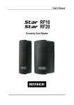
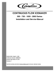
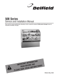
1
F14 SERIES
Service and Installation Manual
Please read this manual completely before attempting to install or operate this equipment! Notify carrier of damage! Inspect all
components immediately.
Hot Food Tables
CAUTION
Important Information
Read Before Use
Please Save These Instructions!
February 2013
F14 Series Service and Installation Manual
Important Warning And Safety Information
WARNING
Read This Manual Thoroughly Before Operating, Installing, Or Performing Maintenance On The Equipment.
WARNING
Failure To Follow Instructions In This Manual Can Cause Property Damage, Injury Or Death.
WARNING
Do Not Store Or Use Gasoline Or Other Flammable Vapors Or Liquids In The Vicinity Of This Or Any Other
Appliance.
WARNING
Unless All Cover And Access Panels Are In Place And Properly Secured, Do Not Operate This Equipment.
WARNING
This Appliance Is Not Intended For Use By Persons Who Lack Experience Or Knowledge, Unless They Have
Been Given Supervision Or Instruction Concerning Use Of The Appliance By A Person Responsible For Their
Safety.
WARNING
This Appliance Is Not To Be Played With.
Warning
Do Not Clean With Water Jet.
WARNING
Do Not Use Electrical Appliances Inside The Food Storage Compartment Of This Appliance.
CAUTION
Observe the following:
2
•
Minimum clearances must be maintained from all walls and combustible materials.
•
Keep the equipment area free and clear of combustible material.
•
Allow adequate clearance for air openings.
•
Operate equipment only on the type of electricity indicated on the specification plate.
•
Unplug the unit before making any repairs.
•
Retain this manual for future reference.
For customer service, call (800) 733-8829, (800) 773-8821, Fax (989) 773-3210, www.delfield.com
F14 Series Service and Installation Manual
Contents
Receiving & Inspecting..........................................................3
Serial Number Location.........................................................4
Warranty Information.............................................................4
Specifications.........................................................................5
Installation
F14EW & F14EI (electric).................................................6
Operation
F14EI (electric).................................................................7
F14EW (electric)..............................................................7
F14GW (gas)....................................................................8
Maintenance...........................................................................9
Wiring Diagrams
Domestic U.S. F14EI (electric).......................................10
Domestic U.S. F14EW (electric)............................... 11-12
Export F14EI (electric)...................................................13
Export F14EW (electric).................................................14
Gas Burner Assembly: F14GW Series..................................15
Delfield Food Warmer (DFW) Assemblies
with thermostatic controls.............................................16
with infinite control........................................................17
Miscellaneous Replacement Parts Lists...............................18
Standard Labor Guidelines...................................................19
Receiving And Inspecting The Equipment
Even though most equipment is shipped crated, care should
be taken during unloading so the equipment is not damaged
while being moved into the building.
1. Visually inspect the exterior of the package and skid or
container. Any damage should be noted and reported to
the delivering carrier immediately.
2. If damaged, open and inspect the contents with the
carrier.
3. In the event that the exterior is not damaged, yet upon
opening, there is concealed damage to the equipment
notify the carrier. Notification should be made verbally
as well as in written form.
4. Request an inspection by the shipping company of the
damaged equipment. This should be done within 10
days from receipt of the equipment.
5. Check the lower portion of the unit to be sure legs or
casters are not bent.
6. Also open the compressor compartment housing and
visually inspect the refrigeration package. Be sure lines
are secure and base is still intact.
7. Freight carriers can supply the necessary damage forms
upon request.
8. Retain all crating material until an inspection has been
made or waived.
Uncrating the Equipment
First cut and remove the banding from around the crate.
Remove the front of the crate material, use of some tools will
be required. If the unit is on legs remove the top of the crate
and lift the unit off the skid. If the unit is on casters it can be
"rolled" off the skid.
For customer service, call (800) 733-8829, (800) 773-8821, Fax (989) 773-3210, www.delfield.com
3
F14 Series Service and Installation Manual
Serial Number Location
The serial number on all F14 Series hot food tables is
printed on the tag located on the plate shelf.
Always have the serial number of your unit available when
calling for parts or service. A complete list of authorized
Delfield parts depots is is available at www.delfield.com.
©2013 The Delfield Company. All rights reserved. Reproduction without
written permission is prohibited. “Delfield” is a registered trademark of The
Delfield Company.
Warranty Information
Visit http://www.delfield.com/minisite/service/warranty_info to:
• Register your product for warranty.
• Verify warranty information.
• View and download a copy of your warranty.
Regulatory Certifications
Domestic Models are certified by:
National Sanitation Foundation (NSF)
Domestic Electirc Models are also certified by:
Underwriters Laboratories (UL)
Underwriters Laboratories of Canada (ULC)
Export Models are certified by:
National Sanitation Foundation (NSF)
European Conformity
Technical Inspection Association
4
For customer service, call (800) 733-8829, (800) 773-8821, Fax (989) 773-3210, www.delfield.com
F14 Series Service and Installation Manual
Domestic U.S Specifications
Electric with individual wells — wet or dry operation
Model
# Of
Openings
Amps
208V/230V
Ship Weight
F14EI232
2
10.0/11.0
216lbs/98kg
F14EI348
3
15.0/16.0
296lbs/134kg
F14EI460
4
20.0/22.0
376lbs/170kg
F14EI572
5
24.0/27.0
456lbs/207kg
F14EI688
6
29.0/32.0
536lbs/243kg
Model
# Of
# Of Gas
Openings* Burners
BTU
Ship Weight
F14GW232
2
1
20000
256lbs/116kg
F14GW348
3
1
20000
326lbs/148kg
F14GW460
4
1
20000
396lbs/180kg
F14GW572
5
2
40000
456lbs/207kg
F14GW688
6
2
40000
536lbs/243kg
*Each opening measures 11.87” x 19.87” (30.2cm x 50.5cm).
Electrical connections are 208/230 volt, 60 cycle, single phase.
Each opening measures 11.87” x 19.87” (30.2cm x 50.5cm).
Electric with single tank — wet operation only
Model
# Of
Openings
Amps
208V/240V
Ship Weight
F14EW232
2
21.0/24.0
316lbs/143kg
F14EW348
3
21.0/24.0
440lbs/199kg
F14EW460
4
21.0/24.0
500lbs/227kg
F14EW572
5
42.0/48.0
560lbs/254kg
F14EW688
6
42.0/48.0
660lbs/299kg
Electrical connections are 120/240 volt, or optional 120/208 volt.
(120 volt circuit is required for the low water cutoff.)
Gas with single tank — wet operation only
Export Specifications
Export Electric with individual wells — wet or dry operation
Model
# Of
Openings
240V/50Hz
Temp Class Watts
Ship Weight
F14EI232-E
2
N
2900
216lbs/98kg
F14EI348-E
3
N
4350
296lbs/134kg
F14EI460-E
4
N
5800
376lbs/170kg
F14EI572-E
5
N
7250
456lbs/207kg
F14EI688-E
6
N
8700
536lbs/243kg
Electrical connections are 240 volt, 50 cycle, single phase.
Each opening measures 11.87” x 19.87” (30.2cm x 50.5cm).
Export Electric with single tank — wet operation only
Model
# Of
Openings
240V/50Hz
Temp Class Watts
Ship Weight
F14EW232-E
2
N
6000
316lbs/143kg
F14EW348-E
3
N
6000
440lbs/199kg
F14EW460-E
4
N
6000
500lbs/227kg
Electrical connections are 240 volt, 50 cycle, single phase.
For customer service, call (800) 733-8829, (800) 773-8821, Fax (989) 773-3210, www.delfield.com
5
F14 Series Service and Installation Manual
Installation: F14EI & F14EW Series (Electric)
Installation should only be done by personnel
certified and licensed to install and maintain
electrical appliances.
Location
Do not install the hot food table near any combustible objects or
surfaces affected by heat or moisture.
Leveling
This unit must be level, both front and back and left to right, in order
to maintain an equal water depth throughout the wells.
Plumbing
Hot water supply connection is provided 36” (91.4cm) above the
floor, 3.12” (7.9cm) from the front left end at the rear of the unit.
You must supply the required 1/2” (1.3cm) NPT connection. The
minimum water pressure is 20psi (138kPa), the maximum water
pressure is 80psi (552kPA).
A waste connection is provided 25” (63.5cm) above the floor, 7.5”
(19.1cm) from the right end. You must supply the required 1”
(2.5cm) NPT connection.
Electrical connection
Connections must be made in accordance with all
applicable local codes and/or the National Electrical
Code. Refer to the wiring diagrams in this manual.
6
For customer service, call (800) 733-8829, (800) 773-8821, Fax (989) 773-3210, www.delfield.com
F14 Series Service and Installation Manual
Operation: F14EI Series (Electric)
Before the unit is used the first time for serving, turn the temperature
knob to “HI” and heat the well for 20 to 30 minutes. Any residue or
dust that adhered to the heater element(s) will be burned off during
this initial preheat period.
When using thick sauces, always operate the hot food well filled with
water. This will provide a more uniform temperature for the sauce.
Wet operation
1) Fill food well with 2” (50mm) of water. For quicker
pre-heating, use hot water to fill the well.
2) Turn the control to “HIGH” and pre-heat the warmer
for 30 minutes.
3) After pre-heating, set the control to your desired
serving temperature.
Steam can cause serious burns. Always wear some
type of protective covering on your hands and arms
when removing lids or pans from the unit. Lift the lid
or pan in a way that will direct escaping steam away
from your face and body.
Dry operation
Never place food directly into the well. Always use
pans.
Only 6” (15.2cm) deep insets should be used with a dry food well.
When operated dry, the bottom of the food well will discolor. A mild
abrasive cleaner is recommended to clean this discoloration.
1) Pre-heat the well on “HIGH” for approximately 15
minutes.
2) After pre-heating, set the control to your desired
serving temperature.
Although these models may be operated either with or without water
in the wells, wet operation is recommended.
Temperature
Always place covers on pans when not serving to prevent food from
drying out and to reduce your operating cost.
Product in pans . . . . . . . . . . . . . . . 140°F to 160°F (60°C to 71°C)
Water in wells . . . . . . . . . . . . . . . . 160°F to 180°F (71°C to 82°C)
For most efficient operation when empty, keep covered insets in
each well during preheating and when the well is not in use.
Do not put food down drain.
Operation: F14EW Series (Electric)
These units must be operated with 4” (102mm) minimum water in
the well. If operated dry, a low water safety switch will interrupt the
electric supply to the heater to prevent heater failure. If the low water
safety switch shuts off power, turn the control to the OFF position.
If the water level is below the heating element, allow the well to cool
completely, then refill with water. Reactivate the well by turning the
control ON and resetting to the previous temperature.
Continuous interruption of power due to a low water level may
disable the heater permanently. Pouring water on a hot heating
element will damage it.
Steam can cause serious burns. Always wear some
type of protective covering on your hands and arms
when removing lids or pans from the unit. Lift the lid
or pan in a way that will direct escaping steam away
from your face and body.
For most efficient operation, when empty, keep covered insets in
each well during preheating and when the well is not in use.
Wet operation
1) Fill food well with 4” (102mm) of water (heater must
be covered by water). For quicker pre-heating, use
hot water to fill the well.
2) S
et the control to your desired serving temperature.
Temperature
Water in wells . . . . . . . . . . . . . . . . 160°F to 180°F (71°C to 82°C)
Product in pans . . . . . . . . . . . . . . . 140°F to 160°F (60°C to 71°C)
Never place food directly into the well. Always use
pans.
Always place covers on pans when not serving to
prevent food from drying out and to reduce your
operating cost.
For customer service, call (800) 733-8829, (800) 773-8821, Fax (989) 773-3210, www.delfield.com
7
F14 Series Service and Installation Manual
Operation: F14GW Series (Gas)
Gas connection
Lighting the pilot
Only qualified and trained personnel
should attempt to light the pilot. Wear
a face shield during this procedure.
Delfield is not responsible for injuries
resulting from attempts to light the pilot.
Only qualified and trained personnel should attempt
to connect the gas. Wear a face shield during this
procedure. Delfield is not responsible for injuries
resulting from attempts connect the gas.
Customer must supply the necessary connection. A pressure
regulated, 1/2” FPT. 20,000 BTU gas supply is required. A gas
regulator is supplied installed.
Be sure the connection is made to maintain flow
through the safety valve in the direction indicated by
the arrow stamped on the valve case. See the gas
burner assembly diagram on page 6.
After installation, check for leaks using a soap solution. Mix some
water with dish or other soap and supply a small amount to the
connection. If bubbles appear, the connection is not correct and
must be reinstalled before operating the unit.
The pilot valve supplied is sized for use with natural
gas. If LP gas is to be used, the pilot fitting must be
changed from the standard .021” (0.53mm) orifice to
a .011” (0.28mm) orifice. This orifice is supplied in a
plastic pouch attached to the plate shelf.
Gas hot food tables must be operated with water in the well. Dry
operation of this unit will cause distortion of the well or other serious
damage.
Steam can cause serious burns. Always wear some
type of protective covering on your hands and arms
when removing lids or pans from the unit. Lift the lid
or pan in a way that will direct escaping steam away
from your face and body.
Never place food directly into the empty well, always
use pans. Never operate burners without water in the
well.
1) Open the gas valve supplying fuel to the hot food
table
2) Push down the reset button on the pilot valve, which
is located behind the control panel, and light the
pilot.
3) Continue to hold down the reset button for 30 to 45
seconds or until the pilot continues to burn when the
button is released.
4) During the reset cycle, gas will flow to both the main
and pilot burners.
5) If the pilot is not lit after steps 1-4 have been
completed, close the gas valve and wait for at least
5 minutes before attempting to light the pilot again.
This should allow any excess gas in the air around
the unit to dissipate. If you are using LP gas, wait
at least 15 minutes; any excess gas will “fall” to the
floor and will require more time to dissipate.
Filling the well and pre-heating
1) With the drain cock closed, fill the well until
approximately a four inch depth is obtained. More
water may be required if shallow depth pans are
used. Always pour water in the well before preheating. For quicker pre-heating use hot water to fill
the well.
2) Turn the gas control knob 1/4 turn counterclockwise
and wait for the water to preheat. Then set the control
to your desired serving temperature.
Temperature
Water in wells . . . . . . . . . . . . . . . . . 160°F to 180°F (71°C to 82°C)
Product in pans . . . . . . . . . . . . . . . . 140°F to 160°F (60°C to 71°C)
Always place covers on pans when not serving to
prevent food from drying out and to reduce your
operating cost.
For most efficient operation, when empty, keep covered insets in
each well during preheating and when the well is not in use.
8
For customer service, call (800) 733-8829, (800) 773-8821, Fax (989) 773-3210, www.delfield.com
F14 Series Service and Installation Manual
Maintenance
Stainless Steel Care and Cleaning
To prevent discoloration or rust on stainless steel several important
steps need to be taken. First, we need to understand the properties of
stainless steel. Stainless steel contains 70- 80% iron, which will rust.
It also contains 12-30% chromium, which forms an invisible passive
film over the steel’s surface, which acts as a shield against corrosion.
As long as the protective layer is intact, the metal is still stainless. If
the film is broken or contaminated, outside elements can begin to
breakdown the steel and begin to form discoloration or rust. Proper
cleaning of stainless steel requires soft cloths or plastic scouring pads.
NEVER USE STEEL PADS, WIRE BRUSHES OR SCRAPERS!
Cleaning solutions need to be alkaline based or non-chloride cleaners.
Any cleaner containing chlorides will damage the protective film of the
stainless steel. Chlorides are also commonly found in hard water, salts,
and household and industrial cleaners. If cleaners containing chlorides
are used be sure to rinse repeatedly and dry thoroughly. Routine cleaning
of stainless steel can be done with soap and water. Extreme stains
or grease should be cleaned with a non-abrasive cleaner and plastic
scrub pad. Always rub with the grain of the steel. There are stainless
steel cleaners available which can restore and preserve the finish of
the steels protective layer. Early signs of stainless steel breakdown are
small pits and cracks. If this has begun, clean thoroughly and start to
apply stainless steel cleaners in attempt to restore the passivity of the
steel.
CAUTION
Never use an acid based cleaning solution! Many food
products have an acidic content, which can deteriorate
the finish. Be sure to clean the stainless steel surfaces of
ALL food products. Common items include, tomatoes,
peppers and other vegetables.
The interior of the food wells should be cleaned daily with a nonabrasive cleaner and non-abrasive pad. If necessary, a mild abrasive
may be used on the interior of the pans only. Hard water stains and
lime scaling may require a special cleaning product. Never use steel
wool.
Never use a high-pressure water wash for cleaning as
water can damage the electrical and gas components.
CAUTION
For customer service, call (800) 733-8829, (800) 773-8821, Fax (989) 773-3210, www.delfield.com
9
F14 Series Service and Installation Manual
Wiring Diagrams: Domestic U.S. F14EI Series
pilot light (furnished)
H1
1000 W - 120V
or 1000/1222 W 208/230 V
heating element
P
L1
L2
H2
line wires
infinite control
with “OFF” position
to additional
food warmers
120 or 208-240V
SINGLE PHASE MODELS
L1
"INFINITE"
CONTROL
G
L2
(NEUTRAL ON 120V MODELS)
HEATER 1
208-240V 3 PHASE MODELS
PILOT LIGHT
L1
HEATER 2
G
L2
L3
PILOT LIGHT
HEATER 3
PILOT LIGHT
HEATER 4
PILOT LIGHT
HEATER 5
PILOT LIGHT
HEATER 6
PILOT LIGHT
10
"INFINITE"
CONTROL
HEATER 1
"INFINITE"
CONTROL
HEATER 3
PILOT LIGHT
PILOT LIGHT
HEATER 4
HEATER 6
PILOT LIGHT
PILOT LIGHT
HEATER 2
PILOT LIGHT
HEATER 5
PILOT LIGHT
For customer service, call (800) 733-8829, (800) 773-8821, Fax (989) 773-3210, www.delfield.com
F14 Series Service and Installation Manual
Wiring Diagrams: Domestic U.S. F14EW Single Phase
120-208 OR 120-240 VOLT SINGLE PHASE SUPPLY
Single Phase
WHITE-NEUTRAL L2-BLACK L1-RED
SWITCH
GREEN-GROUND TO CASE
BLACK
C2
WATER LEVEL
CONTROL BOARD
HEAT
POWER RELAY
120VAC COIL
N
XL HI C
BLUE
LOW WATER LIGHT
BLACK
BLACK
H
TEMPERATURE
CONTROL
RED
FILL
PILOT LIGHT
219-4095
FLOAT
WATER FILL
SOLENOID
IMMERSION
HEATER
THERMAL
OVERLOAD
ON HEATER
WHITE
RED
OPTIONAL
For customer service, call (800) 733-8829, (800) 773-8821, Fax (989) 773-3210, www.delfield.com
11
F14 Series Service and Installation Manual
Wiring Diagrams: Domestic U.S. F14EW Three Phase
120-208 OR 120-240 VOLT THREE PHASE SUPPLY
Three Phase
WHITE-NEUTRAL
SWITCH
L2-BLACK L1-RED
GREEN-GROUND TO CASE
L3-BLUE
RED
C3
BLACK
WATER LEVEL
CONTROL BOARD
POWER RELAY
120VAC COIL
HEAT
FILL
L1-RED
LOW WATER LIGHT
FLOAT
PILOT LIGHT
219-4095
WATER FILL
SOLENOID
RED
THREE PHASE
IMMERSION
HEATER
WHITE
OPTIONAL
12
L3-BLUE
XL HI C
BLUE
L2-BLACK
N
WHITE
TEMPERATURE
CONTROL
RED
H
For customer service, call (800) 733-8829, (800) 773-8821, Fax (989) 773-3210, www.delfield.com
THERMAL
OVERLOAD
ON HEATER
F14 Series Service and Installation Manual
Wiring Diagrams: Export F14EI Series
CONTROL BOX
WIRES FROM CORD
OR BREAKER
GRN W/ YLW 16GA - #MCP00195
GRN W/ YLW 16GA - #MCP00195
L2
L2
INFINITE CONTROL
INFINITE CONTROL
H2
H1
L1
PILOT
PILOT
UNIT
PILOT
PILOT
PILOT
L1
PILOT
PILOT LIGHT
THERMOSTAT
HEATING ELEMENT
H2
H1
L1
PILOT LIGHT
THERMOSTAT
HEATING ELEMENT
INFINITE CONTROL
H2
H1
L1
PILOT LIGHT
THERMOSTAT
HEATING ELEMENT
L2
INFINITE CONTROL
H2
H1
L1
PILOT LIGHT
THERMOSTAT
HEATING ELEMENT
L2
INFINITE CONTROL
H2
H1
L1
PILOT LIGHT
THERMOSTAT
L2
L2
INFINITE CONTROL
H2
H1
PILOT LIGHT
THERMOSTAT
HEATING ELEMENT
HEATING ELEMENT
For customer service, call (800) 733-8829, (800) 773-8821, Fax (989) 773-3210, www.delfield.com
13
F14 Series Service and Installation Manual
Wiring Diagrams: Export F14EW Series
WATER BOARD
C
HI
XL
HEAT
FILL
H
FLOAT SWITCH
N
TERMINAL BLOCK
CONTACTOR
WEGNUT
PILOT LIGHT
HEATING ELEMENT
THERMOSTAT
H1
X2
2
1
5
4
H3
H2
TOGGLE SWITCH
X1
H4
TRANSFORMER
PILOT LIGHT
THERMAL
OVERLOAD
ON HEATER
5000W HEATER ONLY
14
For customer service, call (800) 733-8829, (800) 773-8821, Fax (989) 773-3210, www.delfield.com
F14 Series Service and Installation Manual
Gas Burner Assembly: F14GW Series (Single Shown)
NOTE: The same parts are used for the
double burner assembly
7
2
4
5
8
6
2
2
1
9
10
3
15 16
15
16
15
16
20
2
13
11
17
12
1
14
15
16
18
19
21
23
22
Key
Part #
Description
1
3547413
elbow 1/2” NPT
2
9321035
nut, 1/4-20
3
3547411
manifold nipple, 23”
4
3234205A
gas burner assy
5
3547409
nipple, 3/4 x 12
6
3234341
thermocouple
7
3234342
pilot assembly
8
3547329
tubing, copper, 1/4 O.D. x .028
9
3547407
pipe, manifold, valve, 12”
10
3547408
cap, 1/2 NPT
11
3547234
nipple, 1/2” x 2”
12
3234022
regulator, natural gas
13
3234023
device, vent limiting, gas reg.
14
3547406
nipple, 1/2 x 6.5”
15
9321157
u-bolt, 1/4 - 20
16
9321059
washer, 1/4
17
3234343
valve, safety
18
3234205B
chamber, air mixing
19
3234205C
plate, air mixing
20
3547593
fitting, inlet, burner (natural)
21
3234205D
cock, front handle
22
3234205E
handle, valve
23
3547591
fitting, inlet burner (LP)
24
3547412
nipple, manifold 31.25” dbl bnr only
For customer service, call (800) 733-8829, (800) 773-8821, Fax (989) 773-3210, www.delfield.com
15
F14 Series Service and Installation Manual
Delfield Food Well (DFW) Assembly: With Thermostatic Control
11
2
4
THERMOSTATIC
CONTROL
7
5.5
56
5.
0
Key
1
Description
XMK00100
Complete assembly, 115V, thermostat w/drain
XMK00101
Complete assembly, 115V, thermostat w/o drain
XMK00102
Complete assembly, 208V, thermostat w/drain
XMK00103
Complete assembly, 208V, thermostat w/o drain
1
GMK00061
Deflector plate
2
GMK00062
Bottom cover
3
0160014
Food well, with drain
3
0160015
Food well, without drain
4
9321353
Screw
5
2194006
Element, 115V
5
2194007
Element, 208V
6
9321379
Screws (6)
7
3434663
Insulation
8
3234556
Thermostat control knob
9
2194012
Thermostat, 200-550F
10
2194190
Pilot light, red, 115V
10
2194095
Pilot light, amber, 230V
11
GMK00063
Drain cover
12
9321353
Screws (2)
6
5
12
8.50
2.31
CLE
AR
DRAIN
OPTIONAL
3
NOTE: If you need four or more component parts,
you must buy a complete assembly.
6
9
10
16
Part #
8
For customer service, call (800) 733-8829, (800) 773-8821, Fax (989) 773-3210, www.delfield.com
F14 Series Service and Installation Manual
Delfield Food Well (DFW) Assembly: With Infinite Control
10
2
4
INFINITE
CONTROL
7
Key
1
9
Part #
Description
XMK00104
Complete assembly, 115V, infinite w/drain
XMK00105
Complete assembly, 115V, infinite w/o drain
XMK00068
Complete assembly, 208V, infinite w/drain
XMK00106
Complete assembly, 208V, infinite w/o drain
1
GMK00061
Deflector plate
2
GMK00062
Bottom cover
3
0160014
Food well, with drain
3
0160015
Food well, without drain
4
9321353
Screw
5
2194006
Element, 115V
5
2194007
Element, 208V
6
9321379
Screws (2)
7
3434663
Insulation
8
2194335
Thermostat non-adjustable
9
9321007
Screw
10
GMK00063
Drain cover
11
DRAIN
OPTIONAL 12
9321007
Screws (2)
2194107
Infinite control, 120V
12
2194110
Infinite control, 240V
13
3234557
Infinite control knob
14
2194190
Pilot light, red, 115V
14
2194095
Pilot light, amber, 230V
8
6
5
11
8.50
2.31
3
CLE
AR
NOTE: If you need four or more component parts, you
must buy a complete assembly.
14
12
13
For customer service, call (800) 733-8829, (800) 773-8821, Fax (989) 773-3210, www.delfield.com
17
F14 Series Service and Installation Manual
Miscellaneous Parts Lists
F14EI Series (Electric)
Part Description
Part #
Faucet
3234075
Gate valve 1/2”
3547486
Legs, 6” w/mounting plate
3234645
F14EW Series (Electric)
Part Description
Part #
Brass drain
3234065
Contactor, 2-pole, 220V/50Hz
TBP30021
Contactor, relay 30 amp, 120V
2194185
Faucet
3234075
Float switch
2194156
Gate valve, 1”
3547487
Immersion heater 5KW, 240V, 12.0 amps, 3-phase
2193972
Immersion heater 5KW, 208V, 24.0 amps, 1-phase
2193973
Immersion heater 5KW, 240V, 20.8 amps, 1-phase
2193974
Immersion heater 5KW, 208V, 13.9 amps, 3-phase
2193975
Knob, thermostatic control
3234556
Legs, 6” w/mounting plate
3234645
Light, pilot, 250V, amber
2194095
Relay, socket, KU12
2194133
Relay, 8501, KU12
2194132
Switch
2194400
Thermostat
2194202
Transformer
Waterlevel board
2194187
F14GW Series (Gas)
Part Description
Part #
Faucet
3234075
Gate valve 1”
3547487
Legs, 6” w/mounting plate
3234645
18
For customer service, call (800) 733-8829, (800) 773-8821, Fax (989) 773-3210, www.delfield.com
F14 Series Service and Installation Manual
Standard Labor Guidelines To Repair Or Replace Parts On Delfield Equipment
Advice and recommendations given by Delfield Service Technicians do not constitute or guarantee any special coverage.
•A maximum of 1-hour is allowed to diagnose a defective component.
•A maximum of 1-hour is allowed for retrieval of parts not in stock.
•A maximum travel distance of 100 miles round trip and 2-hours will be reimbursed.
•Overtime, installation/start-up, normal control adjustments, general maintenance, glass breakage, freight damage, and/or
correcting and end-user installation error will not be reimbursed under warranty unless pre-approved with a Service Work
Authorization from Delfield. You must submit the number with the service claim.
Labor Of 1-Hour Is Allowed To Replace:
•Thermostat
•Infinite Switch
•Door Jamb Switch
•Solenoid Coil
•Hi-limit/Thermal Protector Switch
•Fan Delay/Defrost Termination Switch
•Compressor Start Components and Overload Protector
•Defrost Timer
•Thermometer
•Gear Box
•
•
•
•
•
•
•
•
•
Contactor/Relay
Transformer
Evaporator/Condenser Fan Motor and Blade
Circulating Fan Motor and Blade
Microprocessor Control
Water Level Sensor/Probe
Door Hinges, Locks, and Gaskets
Condensate Element
Springs/Lowerator
Labor Of 2 Hours To Replace:
•Drawer Tracks/Cartridges
• Defrost Element
•Pressure Control
• Heating Element
•Solenoid Valve
• Locate/Repair Leak
Labor Of 3 Hours To Replace:
•EPR or CPR Valve
• Condenser or Evaporator Coil
•Expansion Valve
For customer service, call (800) 733-8829, (800) 773-8821, Fax (989) 773-3210, www.delfield.com
19
Covington, TN
Mt. Pleasant, MI
Thank you for choosing Delfield!
Help is a phone call away. Help our team of professional, courteous customer
service reps by having your model number and serial number available at the time
of your call (800) 733-8829.
Model:________________________ S/N: _______________________
Installation Date:________________
For a list of Delfield’s authorized parts depots,
visit our website at www.delfield.com
Register your Delfield warranty
online. Go to www.delfield.com
under the service tab to complete.
980 S. Isabella Rd., Mt. Pleasant, MI 48858, U.S.A. • (989) 773-7981 or (800) 733-8829 • Fax (989) 773-3210 • www.delfield.com
Delfield reserves the right to make changes in design or specifications without prior notice. ©2013 The Delfield Company. All rights reserved. Printed in the U.S.A.
DMF14 02/13
9291453