1
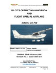
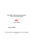
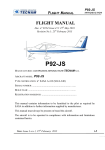
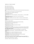
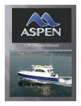
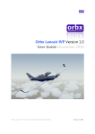
User Manual
Australian Simulation Piper Warrior – Operating Handbook
2
Copyright
Copyright © 2007 Australian Simulation
All rights reserved. No part of this manual may be reproduced, stored or distributed without
the written consent of Australian Simulation.
The information contained in this manual is current as of publication or revision date. Any
part of this manual is subject to change without notice at the discretion of Australian
Simulation.
The current Manual for this aircraft package can be downloaded from the Australian
Simulation web site at www.aussim.com.au/piper/downloads.asp
Published on: Thursday, May 3, 2007
Revision 2
Copyright © 2007-2008 Australian Simulation - All rights reserved.
Australian Simulation Piper Warrior – Operating Handbook
3
Table of Contents
1 - Introduction .......................................................................................... 1.1
About the Piper Warrior ......................................................................... 1.2
Registration Information......................................................................... 1.3
Naming Conventions ............................................................................. 1.3
2 - Specifications....................................................................................... 2.1
Aircraft Overview ................................................................................... 2.2
Performance .......................................................................................... 2.3
3 – Checklists............................................................................................ 3.1
Pre Start................................................................................................. 3.2
After Start............................................................................................... 3.2
Taxi ........................................................................................................ 3.2
Taxi ........................................................................................................ 3.3
Run – Up................................................................................................ 3.3
Pre Take-Off .......................................................................................... 3.3
Pre Take-Off .......................................................................................... 3.4
Take Off ................................................................................................. 3.4
Before Landing ...................................................................................... 3.4
Before Landing ...................................................................................... 3.5
After Landing ......................................................................................... 3.5
Shut Down ............................................................................................. 3.5
4 – Aircraft Information.............................................................................. 4.1
General Information ............................................................................... 4.2
5 – Warrior II Cockpit ................................................................................ 5.1
Panel Layout.......................................................................................... 5.2
Instruments and Controls....................................................................... 5.3
Copyright © 2007-2008 Australian Simulation - All rights reserved.
Australian Simulation Piper Warrior – Operating Handbook
4
Aircraft Control Panel........................................................................... 5.12
VC Yoke Switching .............................................................................. 5.13
FS-X Cameras ..................................................................................... 5.14
6 – Warrior III cockpit ................................................................................ 6.1
Panel Layout.......................................................................................... 6.2
Instruments and Controls....................................................................... 6.3
Aircraft Control Panel........................................................................... 6.24
VC Yoke Switching .............................................................................. 6.25
FS-X Cameras ..................................................................................... 6.26
Copyright © 2007-2008 Australian Simulation - All rights reserved.
1 - Introduction
C
H
A
P
T
E
R
1
Australian Simulation Piper Warrior – Operating Handbook
1.2
About the Piper Warrior
Congratulations on your purchase of the Australian Simulation Piper Warrior Package for
Microsoft™ Flight Simulator.
This aircraft, designed for Microsoft™ Flight Simulator 9 (2004 a Century of Flight) and Flight
Simulator X using the latest 3D design software and programming techniques, offers the best of
the old and new. The result is an excellent representation of what it’s like to fly a real Piper Warrior.
From the accurate flight model, to the just as accurate panels and gauges programmed for each
version of the Warrior.
Whether you’re a student pilot, an experienced aviator or simply a flight simulator enthusiast, you’ll
appreciate the realism that is obtained in this package.
The software designer as well as all of our beta testers has experience flying Piper Warriors, with a
combined total of over 500 hours flying time in this type of aircraft.
This manual contains everything you’ll need to know about the Australian Simulation Piper Warrior.
There are many similarities between this and a real PA28-161 Pilot Operating Handbook, but this
documentation has been written specifically for the Australian Simulation Piper Warrior package.
Supplied checklists are based on real Piper Warrior checklists, but almost every aspect has in one
way or another, been made interactive in this release, thus providing the utmost realism to the
Flight Simulator pilot.
Copyright © 2007-2008 Australian Simulation - All rights reserved.
Australian Simulation Piper Warrior – Operating Handbook
1.3
Registration Information
Please use the area provided to store your registration information for future reference.
Should you ever need to reinstall this package or require assistance from Australian
Simulation support staff, you will need either your serial number or the order number that
was generated at time of purchase.
Registration Information
Order Number: _______________________________
Serial Number: _______________________________
Date of purchase: _____________________________
Purchased from: ______________________________
Naming Conventions
In the process of reading this document you may come across abbreviations for certain
words which may not be immediately obvious to all readers, so the list below identifies
most or all of these abbreviations so everyone is able to understand exactly what we are
talking about.
•
PA28
The aircraft itself. (Piper Warrior II or III)
•
ACP – Aircraft Control Panel
Stand alone software application that ships with this package. Great tool which
allows complete customisation of your aircraft for Flight Simulator.
•
POH – Pilot Operating Handbook
This document.
•
Aussim - Australian Simulation
Developers of this and other Flight Simulation products.
•
VC – Virtual Cockpit
This is the 3D representation of the cockpit, or interior of the aircraft.
Copyright © 2007-2008 Australian Simulation - All rights reserved.
2 - Specifications
C
H
A
P
T
E
R
2
Australian Simulation Piper Warrior – Operating Handbook
Aircraft Overview
See the tables below for detailed information about the Piper Warrior.
Engine
Manufacturer
Model
No. Cylinders
Horsepower
Lycoming
0-320-D3G
4
160 hp
Propeller
No. Propellers
No. Blades
Type
Diameter
1
2
Fixed Pitch
1.85 m
Weights
Max Takeoff Weight
Empty Weight
Useful Load
2,440lbs / 1,107kg
1,536lbs / 697kg
911 lbs / 413 kg
Dimensions
Wing Span
Length
Height
Wing Area
35.0 ft / 10.7 m
23.8 ft / 7.3 m
7.3 ft / 2.2 m
170² ft / 15.8² m
Range
Cruising Range
513 nm / 950 km
45 min fuel reserve @ 55% power @ 10,000 ft best economy mixture.
Copyright © 2007-2008 Australian Simulation - All rights reserved.
2.2
Australian Simulation Piper Warrior – Operating Handbook
Performance
Speeds
Never Exceed (Vne)
Max Speed
Manoeuvring Speed (Va)
Stall Speed Full Flap ( Vso)
Stall Speed No Flap (Vs)
Max Flap ext. Speed (Vfe)
160kts / 297 km/h
117kts / 217 km/h
111kts / 206 km/h
44kts / 81 km/h
50kts / 93 km/h
103kts / 191 km/h
Engine
Max Continuous RPM
Max oil Temp.
Max Oil Pressure
Max Fuel Pressure
2700
473° f / 245° c
100 psi
8 psi
Fuel
Usable Fuel
Approved Type
48 GAL / 182 litres
100 Octane AVGAS
Airframe / Structure
Max Angle of Bank (AoB)
Max Crosswind (Landing)
Approved Manoeuvres
Steep Turns (Entry Speed)
Chandelles (Entry Speed)
Lazy Eights (Entry Speed)
Prohibited Manoeuvres
―
60°
17kts
111kts / 206 km/h
111kts / 206 km/h
111kts / 206 km/h
Spins
Inverted Flight
FLIGHT INTO KNOWN ICING CONDITIONS PROHIBITED
Copyright © 2007-2008 Australian Simulation - All rights reserved.
2.3
3 – Checklists
C
H
A
P
T
E
R
3
Australian Simulation Piper Warrior – Operating Handbook
3.2
Pre Start
Pre – Start Checks
Maintenance Release
Brakes
Circuit Breakers
Fuel Selector
Mixture
Throttle
Primer
Switches
Fuel Pump
Magnetos
Area
Start
Checked and signed
Check Pressure / Set Park brake
SET
ON – Set to tank with least fuel
RICH
CRACKED ~ ½ inch / 1 cm
4-5 Pumps cold start – 1-2 hot start
Master Battery ON - Beacon ON
ON – Check pressure
BOTH
Clear
Start Engine
After Start
After Start Checks
Throttle
Oil Pressure
Fuel Pump
Alternator
Suction
Avionics
Circuit Breakers
ATIS
Set to 1000 RPM
In Green arc within 30 seconds
OFF – Check pressure (Green arc)
ON – Check Charging
CHECK – 2-5 inches
As required
SET
Tune - Check QNH - Set Altimeter
Copyright © 2007-2008 Australian Simulation - All rights reserved.
Australian Simulation Piper Warrior – Operating Handbook
3.3
Taxi
Taxi Checks
Brakes
Turning Left
Turning Right
-
Check pressure and operation
D.G / HSI Turning Left
Magnetic Compass turning left
T.C – Skidding right / Turning left
A.I – Remains erect
D.G / HSI Turning Right
Magnetic Compass turning right
T.C – Skidding left / Turning right
A.I – Remains erect
Run – Up
Engine Run-up Checks
Oil
Power
Left magneto
Right Magneto
Compare
Gauges
Carb. Heat
Idle
Brief
Temp. in green arc
2000 RPM
Switch to: Max drop 175 RPM
Switch to: Max drop 175 RPM
Max differential of 50 RPM L/R Mag.
Check all normal
ON – Check slight drop in RPM
Check – 750 RPM – Reset 1000 RPM
Passenger safety brief
Copyright © 2007-2008 Australian Simulation - All rights reserved.
Australian Simulation Piper Warrior – Operating Handbook
3.4
Pre Take-Off
Before Takeoff Checks
Trim
Mixture
Primer
Fuel
Flaps
Instruments
Switches
Controls
Hatches
Set for Takeoff (Neutral)
RICH
LOCKED
Check pressure – Change Tanks
Check – 3 Stages
Left to Right – Check and Set
BATT ON – ALT ON – MAG BOTH
Check full and free movement
Check Closed – Harnesses ON
Take Off
Takeoff / Line-up Checks
Fuel pump
ON – Check pressure in green arc /
Ensure fullest tank selected
Instruments
Switches
CHECK – D.G. – QNH SET – A.H UP
MAGS BOTH – Strobes ON - Lights
SET to ALT – STBY for Circuits
Transponder
Copyright © 2007-2008 Australian Simulation - All rights reserved.
Australian Simulation Piper Warrior – Operating Handbook
3.5
Before Landing
Pre-Landing Checks
Brakes
Undercarriage
Mixture
Fuel Pump
Oil
Carb Heat
Hatches
Check pressure – Park brake OFF
Down and Locked (N/A for this aircraft)
RICH
ON – Fullest tank selected
CHECK – Pressure & Temp in green
ON
Hatches & harnesses secure
After Landing
After-Landing Checks
Flaps
Fuel Pump
Avionics
Radios
RETRACTED
OFF
Turn off all unnecessary avionics
Set as required
Shut Down
Shutdown Checks
Power
Radios
Magnetos
Shutdown
Keys
Set to 1000 RPM
OFF
Check both for grounding
Close Throttle & Mixture to cut-off
Remove - place on instrument panel
Copyright © 2007-2008 Australian Simulation - All rights reserved.
4 – Aircraft Information
C
H
A
P
T
E
R
4
4.2
Australian Simulation Piper Warrior – Operating Handbook
General Information
Loading
Normal category, Maximum weight 2440 lb, Max baggage 200 lb
+3.8g flaps up, +2g flaps down. No inverted manoeuvres approved.
Utility category, Maximum weight 1950 lb, No baggage
+4.4g and - 1. 76g flaps up, +2g flaps down. No inverted manoeuvres approved
Gliding Range
Engine inoperative, clean and 73kts - 1.73 nm per 1000 ft
Weight – Kilograms (Max Takeoff weight – 1107kg)
Centre of Gravity
1100
(2425lb)
1000
(2205lb)
900
(1984lb)
Normal Category
800
(1764lb)
Utility Category
700
(1543lb)
600
(1323lb)
2100
(83in)
2150
(85in)
2200
(87in)
2250
(88in)
2300
(90in)
2350
(92in)
2400
(94in)
Arm (CoG) – Millimetres aft of datum
Copyright © 2007-2008 Australian Simulation - All rights reserved.
4.3
Australian Simulation Piper Warrior – Operating Handbook
Loading graph
500
Load Weight (Pounds)
400
300
200
100
0
0
10
20
30
40
50
60
Moment / 1000 (pound inches)
Pilot and Front passenger
Aft passengers
Fuel (6lb / GAL)
Baggage
Fuel System
Level Indicator
Left Tank
Right Tank
Fuel Selector
Strainer
To Primer
Fuel Pump
Carburettor
Pressure Indicator
Throttle / Mixture
To Engine
Copyright © 2007-2008 Australian Simulation - All rights reserved.
5 – Warrior II Cockpit
C
H
A
P
T
E
R
5
5.2
Australian Simulation Piper Warrior – Operating Handbook
Panel Layout
10
1
2
3
4
5 6
7
8
9
13
14
11
12
15
16
17
18
19
20
21
22
23
24 25 26 27
1 - Clock
10 - Whiskey Compass
19 - Oil Pressure/Temp.
2 - Airspeed indicator
11 - Turn Coordinator
20 - Tachometer
3 - Directional Gyro
12 - VOR 2
21 - Primer
4 - Attitude indicator
13 - Audio Panel
22 - Throttle/Mixture
5 - Vertical Speed indicator
14 - COM / NAV 1
23 - Carb Heat
6 - Altimeter
15 - Toggle Icons
24 - Ammeter
7 - Annunciators
16 - Autopilot
25 - Switches
8 - VOR 1
17 - E.G.T
26 - Transponder
9 - Avionics Master
18 - Ignition/Magnetos
27 - COM / NAV 2
NOTE: Above is based on main IFR panel only. Instruments and gauges not shown include:
•
Suction Indicator
•
Fuel Selector
•
Circuit Breakers
•
Automatic Direction Finder
•
OAT Indicator
•
Flaps lever & Trim wheels
DME and slaved ADF gauge not shown – this is an addition from version 2
onwards.
Copyright © 2007-2008 Australian Simulation - All rights reserved.
Australian Simulation Piper Warrior – Operating Handbook
5.3
Instruments and Controls
2D Panel Navigation
One of the great features of this release is the intuitive interface. All pop-up windows, and view
options are programmed and displayed in a logical fashion, and therefore little explanation is
required in order for the user to be able to use each feature of the aircrafts panel system.
Having said that, we’ll explain all the main features of the panel navigation system, as well as
instrument / control operation where required.
Switching Views
Possibly the most used switching option is the VFR / IFR view toggle. Upon loading, the
aircraft will display the 2D IFR Panel by default. This is perfect for performing the required
checks, and tuning of instruments. But when it comes time to do the real flying (takeoff and
landing) you’ll want a good view of the outside world. Simply click on the dashboard to swap to
& from IFR or VFR view. A large invisible spot has been created to allow quick and easy
access to this trigger. So when the pressure is on, you wont be looking for a small icon or
trying to manage difficult keystroke combinations.
To switch between IFR / VFR
views, click on the dash area.
Copyright © 2007-2008 Australian Simulation - All rights reserved.
5.4
Australian Simulation Piper Warrior – Operating Handbook
Window Icons
Due to the abundance of features included in this panel, many of the available
instruments and gauges are hidden from initial view. On the main IFR panel you’ll notice
a row of icons directly above the autopilot. These provide quick and easy access to the
various pop-up windows that contain these extra gauges.
When in VFR mode, the only initially visible icon has four small squares on the face.
Clicking this icon will open a small window that fits snugly on the side of the radio stack
with icons for all available pop-up windows.
This saves the user from having to revert back to the IFR screen to perform such
operations.
Main / IFR Panel
Press to Show icons (VFR)
VFR Panel
Large Radio Stack
Show ADF
Show GPS
ATC Window
Show Map
Show Kneeboard
Lighting Window
Elevator Trim
Rudder Trim
Flaps Lever
Circuit Breakers
Close Toggles
Copyright © 2007-2008 Australian Simulation - All rights reserved.
Australian Simulation Piper Warrior – Operating Handbook
5.5
Invisible Hotspots
Some of the available windows do not have a corresponding icon associated with them.
We have used icons only where it was either not possible, or not practical to place an
invisible ‘hotspot’ or click spot.
As with the IFR / VFR switching, we have used these invisible spots wherever possible,
to maximise the level of realism when flying the PA28.
See below for a diagram of invisible ‘hotspots’ and what they control.
IFR / VFR View
OAT Indicator
Yoke
Fuel Selector
= Click Spot
Circuit Breakers
Copyright © 2007-2008 Australian Simulation - All rights reserved.
5.6
Australian Simulation Piper Warrior – Operating Handbook
Avionics
The avionics installed in the Piper Warrior II panel, consists of a couple of old Bendix/
King KX175 COM/NAV Transceivers, KMA 24 Audio Panel, KT76 Transponder and a
KR86 ADF. Operation of all of these instruments is relatively straight forward, and should
present no problems t users. Below is a brief set of instructions of: how to adjust
frequencies, effects of switches and overall operation.
Marker Lights
Audio Controls
Selector Switch (Non Functional)
Audio Panel
COM1 Frequency
COM / NAV 1
NAV1 Frequency
NAV2 Frequency
COM / NAV 2
COM2 Frequency
Transponder Code
Transponder
Mode Selector
Interrogation LED
COM / NAV Radios
Adjusting the NAV / COM Frequencies is achieved either by clicking on the area over the
frequency display, or the adjustment knob to the right.
The area immediately above the selector knob, switches the COM transceiver between
OFF | ON | TEST modes. These perform limited functions, and are mainly for animation
purposes. If the NAV transceiver is in the off position, instruments such as VOR1 or 2 will
not operate relative to the NAV radio.
Fraction Increase
Whole Increase
Decrease Selector
Advance Selector
Whole Decrease
Whole Increase
Fraction Decrease
Fraction Increase
Fraction Decrease
Whole Decrease
Copyright © 2007-2008 Australian Simulation - All rights reserved.
Australian Simulation Piper Warrior – Operating Handbook
5.7
Transponder
Adjusting the Transponder code is done via the knobs below each number. The left side
of each knob decreases its corresponding number, and the right increases the number.
The mode selector knob, located on the left side of the unit, is adjusted in the same way
as most knobs/switches on the panel. Clicking on the left side of the knob will decrease,
or turn counter-clockwise. Whilst clicking on the right will increase or turn clockwise.
Decrease
Increase
Automatic Direction Finder
The Automatic Direction Finder (ADF) installed in the Warrior II, is of the dual
tuner/indicator type. Adjustment is done in exactly the same fashion as the other avionics
equipment in that clicking on the left of a knob, decreases the relative selection, and
clicking on the right increases selection.
The direction indicator will point directly towards a tuned NDB (Non Directional Beacon) if in
range, and there are no electrical or avionics problems with the aircraft.
This instrument includes an adjustable heading card. This can be very useful for
navigation and is adjusted via the knob located on the lower-right of the ADF indicator.
ADF Indicator
Heading Card
Heading Card Adjust
Tip
A useful tip is that each knob, whether it is in Virtual Cockpit mode or
2D panel mode, can be rotated by using your mouse wheel. This is
especially useful for making larger adjustments. For example, when
adjusting the heading bug on the directional gyro, using the mouse
wheel will take a fraction of the time as it would take to click through
your selection.
Copyright © 2007-2008 Australian Simulation - All rights reserved.
Australian Simulation Piper Warrior – Operating Handbook
5.8
Autopilot
The Warrior II includes the ‘Piper Autocontrol IIIB’ autopilot module. This is a very basic
autopilot that performs minimum control functions. It is limited to aileron axis only,
therefore no pitch control must be maintained by the pilot.
There are 3 knobs present on this gauge, and operate as follows;
• Autopilot Master Switch
Clicking on this switch will engage / disengage the autopilot.
• Roll Control
When autopilot is activated, it will maintain current heading. Any aileron input by
the pilot will be ignored.
Turning the roll knob to the right (Clicking on the right side of knob) will initiate a
90% standard turn to the right (starboard) whilst the knob is turned. Releasing the
mouse will return knob to the central position, and new heading will be
maintained.
Similarly, turning the knob to the left will enable the autopilot to perform a 90%
standard turn to the left (port). Again, releasing the mouse button will level wings
and continue on new heading.
*NOTE: Whilst performing roll manoeuvres with the autopilot, take care NOT to
move joystick during the turn, as the aircraft will react to these inputs. This is due
to the limitations within flight simulator, as the roll function has been specially
programmed into the gauge.
• Heading Control
When this function is activated (Right side switch) the autopilot will maintain the
heading set on the Directional Gyro heading bug. Any changes to the heading
bug setting will be reflected in real-time by the autopilot.
Throttle / Mixture Control
The Throttle and Mixture controls for the Warrior II operate as
one would expect. Clicking and dragging the handle of each lever
will ramp up or down the selected lever.
We have also programmed the mouse wheel option into this
gauge to allow minor adjustments (as low as 1% per wheel
notch) This allows extremely accurate control over power and
mixture settings.
Copyright © 2007-2008 Australian Simulation - All rights reserved.
Australian Simulation Piper Warrior – Operating Handbook
5.9
Electrical System
Switches
Directly below the avionics / radio stack, you’ll find the main switch panel. These switches
control (in order) NAV Lights – Master Battery – Master alternator – Fuel Pump – Landing
Light – Strobe Lights – Pitot Heat – Panel/Gauge Lights.
Clicking on any switch will change its state (ON/OFF).
Interior Lighting
Another original feature of this package is the interior
lighting control. Clicking on the light-bulb icon will open
the interior lighting window. The lower part of this window
controls the traditional red panel lighting that we are all
familiar with. *We have added a dimmer function to this light
for simulation purposes, though this has no effect on the 2D or
VC lighting level.
The larger white light is the dome light, similar to that
which would be in your car. Clicking on the adjacent
switch will activate this light.
*NOTE: The effects of this light are not visible in 2D panel
mode.
*NOTE: Also controllable from VC.
Red Cabin Light Control
White Cabin Light Control
Copyright © 2007-2008 Australian Simulation - All rights reserved.
5.10
Australian Simulation Piper Warrior – Operating Handbook
Trim Controls
Pitch Trim
Trimming the aircraft is achieved via the pitch trim
controls in either 2D or Virtual cockpit modes. The
2D pitch trim is controlled by clicking the upper or
lower part of the trim wheel or using the mouse
wheel over any part of the trim wheel in the 2D pitch
trim window.
In Virtual Cockpit mode, you can control trim in the
same way, with the additional feature of being able
to “Click and drag” the wheel in either direction.
*NOTE: Current amount of trim is indicated in the
2D pitch trim window.
2D Pitch trim
Virtual Cockpit Pitch
Rudder Trim
Trimming the rudder is achieved via the rudder trim
controls in either 2D or Virtual Cockpit modes. The
2D rudder trim is controlled by clicking on the left or
right side of the adjustment knob. Virtual Cockpit
rudder trim is controlled in the same way, with the
addition of being able to “Click and drag” the knob.
*NOTE: Trim position indicator is located in the 2D
rudder trim window only.
2D Rudder trim
Virtual Cockpit Rudder trim
*NOTE: The Warrior II is not fitted with Aileron trim
Flaps Control
Extending / retracting flaps is performed via either
the 2D flaps pop-up window, or the Virtual Cockpit
flaps lever.
In 2D mode, click the upper end of the flaps handle
to extend flaps (1 click = 1 stage of flap) and clicking
on the lower end of the lever retracts flaps
incrementally.
In Virtual Cockpit mode, to extend or retract flaps,
click on the lever and drag the mouse up or down.
VC Flaps lever
Tip
2D Flaps lever
You can jump between flaps and pitch trim windows in 2D panel mode by clicking on
either the trim wheel, or flaps lever.
For example, when flaps window is open, clicking on the trim wheel will close flaps
window and open pitch trim window and visa versa.
Copyright © 2007-2008 Australian Simulation - All rights reserved.
Australian Simulation Piper Warrior – Operating Handbook
5.11
Warning Lights
There are three basic warning lights located on the
upper part of the Warrior II panel. These are; VAC –
Vacuum Warning, ALT – Alternator Warning, OIL – Oil
Temperature/Pressure Warning.
On the left of these indicators is a switch labelled “Press
to test”. Clicking this switch will illuminate the three
lights for a period of approximately 3 seconds. This is to
ensure that all lights are in working order prior to
commencement of flight.
Other Instruments
The remaining instruments in the Warrior II require no extended explanation. Even
though each gauge has been programmed from scratch, they still operate as one would
expect. Some features that are noteworthy however are:
• True Airspeed calibration (Airspeed Indicator)
• Pitch bar adjustment +/- (Attitude Indicator / Artificial Horizon)
• QNH Adjustment (Altimeter)
• Magnetic Correction (Directional Gyro)
• Heading bug adjustment (Directional Gyro)
• Engine Primer (Must be pumped > 3 times for cold start)
• Lighting (Using keyboard short-cut for landing lights will not work as expected, this
is due to the use of the landing light tag for the VC gauge backlighting. Taxi light
has been used in place of the landing light.)
• Virtual Cockpit Sun visors – Click on either sun visor in VC mode to raise / lower.
• Virtual Cockpit Cabin Air – Click on the Cabin Air Lever in VC mode for aft seating
air conditioned air (animation only)
• Virtual Cockpit Exit – Clicking on either exit handle in VC mode will open / close the
main exit.
• Virtual Cockpit Storm Window – Clicking on the storm window latch in VC mode,
will open / close this window. (Don’t forget to yell “CLEAR PROP!”)
• Slaved ADF indicator – this is simply a stand alone ADF indicator which displays
exactly the same ADF data as the avionics mounted version, however, it’s placed
within easy sight of the pilot from 2D of 3D viewpoints.
• Analogue DME gauge – we have modelled an accurate analogue DME gauge after
popular request. This gauge is slaved to NAV1 and will read distance in Nautical
miles. When the button is pressed and held, (lower right) DME speed is displayed
on the adjacent scale.
Copyright © 2007-2008 Australian Simulation - All rights reserved.
Australian Simulation Piper Warrior – Operating Handbook
5.12
Aircraft Control Panel
The Australian Simulation Piper Warrior II version 2 and above, has a new addition, the
“ACP” window. This is a small window that represents an in game version of the Aircraft
Control panel Software that ships with this package.
This allows real-time control over the same variables as are available in the Aircraft
Control Panel program. The changes you make during your flight are only saved for that
particular flight. As soon as you reload the aircraft, or load another aircraft, the changes
you made in the “in-game ACP” will be lost.
To make permanent changes to these options, use the Aircraft Control Panel program
instead.
To open the in-game ACP window, you can either select it from your “Views Æ Instrument
panel” menu by selecting the ACP menu item, or you can use the keyboard shortcut
SHIFT+4.
To make a change, simply click the checkbox that is adjacent to any item. Your change will
be made instantly, and the checkbox will display a tick or an X depending on your
selection.
NOTE: This window will always load the changes saved from the Aircraft Control Panel
program.
The in-game ACP window
Copyright © 2007-2008 Australian Simulation - All rights reserved.
Australian Simulation Piper Warrior – Operating Handbook
5.13
VC Yoke Switching
Another new feature in the Australian Simulation Piper Warrior version 2.0 and above, is
the ability to switch visibility of the VC yokes in real-time. You’ll agree that this function
greatly improves the usability of the cockpit in VC mode.
For example, try turning the ignition key when the yokes are visible… it’s a camera
adjusting nightmare!
In the Warrior II cockpit, simply click the panel extensions from which the yoke poles
protrude. Left clicking this area will switch the visibility of the yokes instantly.
You can also use the in-game ACP window, though this method is slightly cumbersome.
Now you see them…
Left-Clicking the areas shown will
switch the visibility state of the
Yokes.
As you pass the mouse cursor over
these areas, the cursor icon will
change to a hand.
NOTE: The in-game ACP window
will display the current status of
yoke visibility in real-time, so if you
change the visibility using the clickspots show here, the ACP window
will update itself automatically.
Now you don’t!
Copyright © 2007-2008 Australian Simulation - All rights reserved.
Australian Simulation Piper Warrior – Operating Handbook
5.14
FS-X Cameras
Flight Simulator-X™ users have a few extra features available to them by using the new
camera system. The Australian Simulation Piper Warrior comes pre-loaded with a whole
host of additional camera views for both the external 3D model and the virtual cockpit.
To cycle through these views, press the “A” key, or “SHIFT+A” key combination to cycle
either forwards or backwards.
NOTE: The above assumes that you haven’t changed the default keystrokes for the
alternate camera view system.
The views available are as follows:
External Views –
• Right Wing Cam
Camera is positioned just behind the right wing, looking towards the cockpit.
•
Left Wing Cam
Camera is positioned just behind the left wing, looking towards the cockpit.
•
Tail Cam
Camera is positioned immediately behind the vertical stabiliser looking forward
across the top of the aircraft.
•
Gear Cam
Camera is positioned immediately behind the right landing gear looking forward.
•
Nose Cam
Camera is positioned immediately behind and above the prop spinner, with a zoom
level of 0.3, giving a wide field of view.
•
Reverse Nose Cam
Camera is positioned in front, and to the right of the nose section, looking back
towards the cockpit.
Copyright © 2007-2008 Australian Simulation - All rights reserved.
Australian Simulation Piper Warrior – Operating Handbook
5.15
Internal / VC views –
• Default view
This is the standard view from the pilots seat.
•
Co-pilot, or passenger view
This is the same as the default view, except you are positioned in the right hand
seat.
•
Engine Controls
This view places the camera directly in front of the throttle and mixture levers. This
view also provides an excellent view of the switch panel, tachometer, DME gauge,
ignition switch, ammeter and fuel/oil instruments, as well as the park brake, carb
heat switch and rudder trim.
•
Centre Console
This places the camera immediately above the flaps and elevator trim console.
•
Avionics
Here we can see a great view of the radio stack, ADF and the VOR 1 & 2 gauges.
•
Main instruments
This view places the camera low on the panel, directly in front of the main
instruments and provides an excellent way of practicing IFR training.
•
2D panel system
The final position in the cycle, displays the standard 2D panel system. We would
recommend doing all your flying from the Virtual Cockpit though, as every function
that is available in 2D mode, is also available in VC mode.
Copyright © 2007-2008 Australian Simulation - All rights reserved.
6 – Warrior III cockpit
C
H
A
P
T
E
R
6
6.2
Australian Simulation Piper Warrior – Operating Handbook
Panel Layout
15
17
16
2
3
4
6
7
8
9
11
12
13
14
1
5
10
21
22
23
24
25
18
19
20
26
27
28
1 - Clock
11 – Oil Temp. / Press
21 – Ignition / Magnetos
2 – Airspeed Indicator
12 – E.G.T.
22 – Elec. Primer
3 – Attitude Indicator
13 – Fuel Quantity
23 – Elec. Trim
4 - Altimeter
14 - Tachometer
24 - Dimmers
5 - Suction
15 – Alternate VAC
25 – Carb. Heat
6 – S30 Autopilot / T.C.
16 – E.L.T.
26 - Switches
7 – H.S.I.
17 – Annunciators
27 – Circuit Breakers
8 – V.S.I.
18 – Avionics
28 – Air Conditioning
9 – VOR 2
19 – Becker 3500 ADF
10 – ADF Indicator
20 – Digital Ammeter
Copyright © 2007-2008 Australian Simulation - All rights reserved.
Australian Simulation Piper Warrior – Operating Handbook
6.3
Instruments and Controls
2D Panel Navigation
As with the Warrior II, the Warrior III interface has been designed to be intuitive. Navigating
through the various views is a simple process, involving only clicking the relevant button.
We felt that the design philosophy we implemented on the Warrior II panel was not entirely
complimentary to the new look Warrior III panel. So we created animated navigation
buttons which remain uniform throughout the various views in this aircraft.
Switching Views
The Warrior III panel consists of four main views, IFR Pilots view (default) IFR Co pilots
view, VFR Pilots view and VFR Co Pilots view. Among these are various pop-up windows
allowing access to the various controls and instruments that don’t fit well onto the active
Scroll through views via arrow buttons
Copyright © 2007-2008 Australian Simulation - All rights reserved.
6.4
Australian Simulation Piper Warrior – Operating Handbook
Window Buttons
For this aircraft, we have created a series of push-buttons for toggling the various pop-up
windows, and views that are available to the pilot. Looking at any of the buttons should
be enough to determine what they do, but the table below explains each one individually.
Map
Fuel Selector
OAT
Kneeboard
Lighting
Flaps
Radio Stack
ATC Window
ADF
Compass
View Change
Avionics
Possibly the most advanced feature of this aircraft package, is the avionics installed in
the Warrior III. Featuring a full suite of Apollo / Garmin Avionics consisting of a GMA340
Audio panel, two SL30 COM / NAV Transceivers, a Garmin 500 GPS, a GTX-327
Transponder and a Becker 3500 ADF Transceiver.
Audio Panel
COM / NAV 1
COM / NAV 2
GPS 500
Transponder
Becker ADF
Copyright © 2007-2008 Australian Simulation - All rights reserved.
6.5
Australian Simulation Piper Warrior – Operating Handbook
Operation
Garmin GMA-340 Audio
The Garmin GMA 340 Audio panel is one of the most advanced of its type. Featuring
Outer, Middle and Inner marker lights as well as audio control for all installed avionics.
Flight Simulator has no facility for every feature available to this instrument, however, all
buttons and LED’s have been programmed to be interactive.
For example, the marker beacon sensitivity is non-functional in Flight Simulator, but the
corresponding button clicks and sensitivity LED’s have still been programmed so as to
appear to be fully functional.
Marker Lights
Non functional buttons
Marker mute
Marker Sensitivity
COM Audio Selectors
(COM3 non functional)
COM to Both
Press to test
Ident Audio Control
Each button on this gauge has been programmed to be interactive, regardless of whether
there is any real function performed. When the mouse is clicked on a button, the button
will animate. The button will appear in for the duration of the mouse click. The associated
LED for each button will also illuminate / extinguish for every mouse click.
Button functions
•
•
•
•
•
MKR|MUTE
When the button LED is illuminated,
you will not hear marker sounds,
however the AOM lights will still work
as normal. To mute, press once, to unmute, press again.
SENS
This button controls the marker
sensitivity LED’s. Each press swaps
between HI / LO.
COM1 / COM1 MIC
These buttons have been programmed
to act as one in terms of their
operation. A mouse click will set audio
to COM1
COM2 / COM2 MIC
Sets Audio to COM2
COM3 / COM3 MIC
Animation only, no Flight Simulator
function.
•
•
•
•
•
•
•
•
•
•
NAV1
Sets audio to NAV1 Ident.
NAV2
Sets Audio to NAV2 Ident.
DME
Sets audio to Tuned DME Ident.
ADF
Sets Audio to ADF Ident.
TEST
Pressing this button tests all LED’s.
COM2 1/2
Sets COM Audio to receive BOTH.
SPKR
Animation and LED only.
PA
Animation and LED only.
PILOT
Animation and LED only.
CREW
Animation and LED only.
Copyright © 2007-2008 Australian Simulation - All rights reserved.
6.6
Australian Simulation Piper Warrior – Operating Handbook
Apollo SL30 NAV/COM
The Apollo SL30 COM/NAV Transceiver(s), produced by Garmin, are extremely versatile.
Despite their size, they boast an excellent range of features, all of which have been
programmed into these gauges in way or another.
It is important that this section of the manual be understood, in order to get the most out
of these advanced avionics.
+/-
Active COM(1/2)
Active Freq.
Flip-Flop
Mode LED’s
Mode Buttons
Standby Freq.
Advanced
Options
Modes overview
The SL30 has two main modes of operation, COM Mode, and NAV Mode. Put simply,
when in COM mode, the Active and standby frequencies displayed are the COM
(Communications) frequencies. Similarly, when in NAV mode, the frequencies displayed
are the NAV (Navigation) frequencies.
The current mode is indicated via the small LED (Light emitting diode) located directly
above the COM, NAV, SYS and OBS buttons.
Following is a brief description of each mode.
• COM MODE
Radio is currently displaying Communication frequency information.
Communications frequency can be adjusted ONLY in this mode.
• NAV MODE
Radio is currently displaying Navigation frequency information.
Navigation frequency can be adjusted ONLY in this mode.
• SYS MODE
This is the System mode. Whilst in this mode, the radio set performs a continuous
loop of self tests, no information is displayed on screen during this time. To exit,
simply select either COM or NAV modes.
• OBS MODE
This mode is only available if it is selected whilst in NAV mode. The radio has
been wired to both the H.S.I (Horizontal Situation Indicator) and VOR2 (Variable
Omni-Range), allowing OBS radial information to be displayed on the extreme
right window of the SL30 radio. If an active VOR is tuned, a graphical CDI bar
(Course Deviation indicator) will be displayed, as well as TO/FROM station
information.
See later in this document for detailed information about OBS mode.
NOTE: Each mode is accessed by pressing the associated mode button.
Copyright © 2007-2008 Australian Simulation - All rights reserved.
6.7
Australian Simulation Piper Warrior – Operating Handbook
Basic Operation COM / NAV mode
By default the Apollo SL30 COM/NAV Transceiver(s) will start in COM mode. This is
indicated by a small LED (Light) above the COM button. The current active frequency is
displayed on the far left, while the standby frequency is displayed to the right. The
standby frequency has a small “s” next to the frequency to indicate standby status.
Adjusting / Setting COM & NAV Frequency
Adjusting and setting the COM or NAV frequency is a
simple task.
*NOTE: The frequency that is adjusted is actually the
STANDBY frequency, once desired frequency is set in the
standby window, simply press the FLIP-FLOP button to set
as active frequency.
Simply click on the areas indicated in the diagram to the
right to adjust frequency. You can make the adjustment
from either the standby frequency window, or the knob
located on the far right of the SL30 gauge.
Once the frequency is adjusted to the desired setting, press
the FLIP-FLOP button to set to active frequency.
+
-
Whole Number adjust
Fraction adjust
+
-
TX Symbol
To save the frequency, simply press the SEL button.
(This is the button immediately to the left of the ENTER
button, and is known as the SELECT button.)
Once you have pressed the button, the standby
frequency is saved to this location… it really is as
simple as that!
*TIP: You can also use the
mouse wheel to adjust the
frequency.
Advanced Operation COM / NAV mode
The SL30 NAV/COM transceiver has many advanced options built into the gauge.
Following is a description of each function, and its method of operation.
COM / NAV Memory Functions
The SL30 NAV/COM transceiver has 10 memory locations for storing frequencies, 5 are
reserved for COM frequencies, and 5 more are reserved for NAV frequencies. These
memory locations all have names associated with them to allow logical saving and
recalling operations, as well as making them relatively easy to remember. The save
location names are as follows:
COM MEMORY
• ATS (ATIS)
• ATC1
• ATC2
• GND (GROUND)
• TWR (TOWER)
NAV MEMORY
• VOR1
• VOR2
• VOR3
• ILS1
• ILS2
Copyright © 2007-2008 Australian Simulation - All rights reserved.
Australian Simulation Piper Warrior – Operating Handbook
6.8
Storing a frequency
Saving a frequency for later use is a relatively simple task; simply follow the instructions
below to store a frequency to a memory location in either COM or NAV mode.
The example we use is to store several COM frequencies for Meigs field airport located in
Chicago, U.S.A. We will then recall some of these frequencies setting one to active, and
readying another in the standby window.
Following this example, will teach you to use the store and recall feature in either COM or
NAV mode easily.
Load up your simulator and go to Meigs field (KCGX), select any variation of the
Australian Simulation piper Warrior III. In either VC or 2D panel mode (we recommend,
2D panel, with the large Radio Stack window opened) focus on COM/NAV1 and ensure the
radio is in COM mode.
First we will save the local ATIS frequency to the ATS memory location.
Set the standby frequency to 127.35 and then press the ENT button. (This is the button on
the extreme right, and is known as the ENTER button)
After pressing this button, you will see the “STORE AS” message appear in the right
window, followed by “ATS”.
Because “ATS” is the first available
memory location, and this is a
logical name for the current
frequency, we’ll save our standby
frequency to this location.
To save the frequency, simply press the SEL button. (This is the button immediately to the
left of the ENTER button, and is known as the SELECT button.)
Once you have pressed the button, the standby frequency is saved to this location… it
really is as simple as that!
But while we are here, we’ll also save the aerodrome’s ground frequency.
Back to the standby frequency, we can now set: 121.80 which is KCGX Ground. If
“STORE AS” is not already displayed, click the ENT button once. We have already used
the “ATS” location, and we don’t want to overwrite it, so we’ll select the “GND” location for
this frequency.
To select the GND save location, we need to scroll through the list of available memory
locations by clicking on the right or left side of the knob (extreme right) or the left/right
side of the memory name label.
Scroll through until you see “GND” displayed on the right side window, and press
ENTER.
*TIP: You can use the mouse wheel to scroll through save names.
Copyright © 2007-2008 Australian Simulation - All rights reserved.
Australian Simulation Piper Warrior – Operating Handbook
6.9
Recalling a frequency
Now we have successfully saved two frequencies, we will now recall them from memory.
Upon recalling the desired stored frequency, the SL30 will enter the recalled frequency
into the standby window.
*Before continuing, please ensure you have exited the SAVE mode. If you see “STORE
AS” in the right window, simply press ENT to exit save mode.
Assuming we are still in COM mode, press the SEL button, you will see “RECALL”,
followed by “ATS”.
To recall the frequency we saved in the ATS location, press ENT. This will enter the
Meigs Field ATIS frequency into the standby window.
Now press the FLIP-FLOP button to set this frequency as active.
While we are still in RECALL mode, we’ll set the frequency we saved in the GND memory
slot as the standby frequency.
Scroll through the RECALL NAME list until the GND slot is displayed. Once you have
done this, simply press the ENT button, and the KCGX Ground frequency will be entered
in the standby window.
Press SEL again to exit RECALL mode.
Now we have saved and recalled two frequencies, these frequencies will remain in their
saved locations until they are overwritten, or you exit flight simulator.
Saving NAV frequencies is done in exactly the same way as above. Any frequency can
be stored to any location; the naming convention used is merely a guide as to what you
intend to save/recall. Just because than save name is called ATS, you don’t have to enter
an ATIS frequency. Just remember what you store and where.
You are probably already imagining the benefits of using this feature, prior to
commencing a cross-country flight, you can store all the COM and NAV frequencies that
you’ll need before you leave the ground, leaving you more time to concentrate on flying
the aircraft.
With the two SL30’s installed in the Warrior III, you have a total of 20 memory locations
available.
Copyright © 2007-2008 Australian Simulation - All rights reserved.
Australian Simulation Piper Warrior – Operating Handbook
6.10
Advanced Options (NAV MODE)
OBS MODE
OBS mode is actually a sub-mode of NAV mode. This means that it is only accessible
from NAV mode. Pressing the OBS button in any other mode will have no effect.
Once in NAV mode (enter NAV mode by pressing the NAV button), tune an active VOR, and
set as active frequency.
In the example below, we have tuned O’Hare International airport (Chicago, U.S.A) VOR
as NAV1 active frequency. We have also set our H.S.I. (Horizontal Situation indicator) to
course 326.
Pressing the OBS button on the SL30 will display the following information:
• Course Setting
• TO / FROM Station data
• Graphical CDI (Course Deviation Indictor)
Course Setting (326) / Display
TO/FROM
CDI Bar
Bear in mind that this example applies specifically to COM/NAV-1. For COM/NAV-2 we
would use the VOR-2 gauge.
As we intercept the 326 radial from the tuned VOR, the CDI bar moves into the centre
just like on the H.S.I.
To exit OBS mode, press the OBS button, or the COM button.
Copyright © 2007-2008 Australian Simulation - All rights reserved.
Australian Simulation Piper Warrior – Operating Handbook
6.11
Advanced Options (T/F MODE)
T/F MODE
T/F mode is also a sub-mode of NAV mode. This means that it is only accessible from
NAV mode. Pressing the T/F button in any other mode will have no effect.
Once in NAV mode (enter NAV mode by pressing the NAV button), tune an active VOR/DME,
and set as active frequency.
Continuing on from the previous example, we have tuned O’Hare International airport
(Chicago, U.S.A) VOR/DME as NAV1 active frequency.
T/F mode has 3 sub-modes, each time the T/F button is pressed the SL30 will display the
following information:
1. Bearing TO VOR station
2. Radial FROM VOR station
3. DME data (Distance Measuring Equipment)
*NOTE: If tuned station is not active, or signal strength is too weak, the display will read
“VOR” followed by “- - -“. The DME data will also show “- - -“where numerals would
normally be displayed.
Signal strength insufficient for
resolving data accurately, or
active frequency not a VOR.
First press T/F button. VOR text
replaced with tuned station IDENT
name, bearing TO station shows
325 degrees.
Second press T/F button. Tuned
station ident name, radial
FROM(FR) tuned station shows
145 degrees.
Third press T/F button. DME data
is displayed. (see below)
DME data can be broken down into three areas. 1) Distance TO/FROM station (displayed
in Nautical Miles) 2) Current speed TO/FROM station (displayed in Knots) 3) Estimated time
of arrival at station (displayed in hours:minutes).
To exit T/F mode, press T/F button a fourth time.
Copyright © 2007-2008 Australian Simulation - All rights reserved.
Australian Simulation Piper Warrior – Operating Handbook
6.12
GTX-327 Transponder
Overview
Not to be topped by the other avionics installed in the Australian Simulation Piper
Warrior III, the Garmin GTX 327 Transponder also features many advanced options.
These include Altitude data, flight time counter, count-up and count-down timers.
Basic Options
Advanced Options
LCD Screen
Reply symbol. This flashes during interrogation from ATC radar.
Basic Operation
Adjusting Squawk Code
The most basic facet of operation of the transponder is adjusting the squawk code. This
is done in much the same way as adjusting the frequency of the COM/NAV radios in that
clicking the upper part of each number will increase that number, while clicking the lower
half of the number will decrease that number. See below.
Basic Functions
The buttons located on the upper-left area of this instrument control the basic functions of
the transponder. Some need no explanation, such as the ON & OFF buttons, but others
require some brief explanation to ensure the user understands what the instrument does.
• IDENT - Displays IDENT on the upper-left corner of the LCD screen.
• VFR - Sets the squawk code to 1200 (use this setting while flying circuits, or not
under ATC control, and set STBY)
•
•
STBY - Used in conjunction with VFR mode, use this mode when not under
ATC control. (STBY is displayed on the left of screen)
ALT - Allows transmition of Altitude data when transponder is interrogated by
ATC radar. (ALT is displayed on left of screen)
Copyright © 2007-2008 Australian Simulation - All rights reserved.
Australian Simulation Piper Warrior – Operating Handbook
6.13
Advanced Operation
Function Modes
The FUNCTION button located to the upper-right corner of the transponder controls
several advanced options. Each time the FUNCTION button is pressed, the transponder
scrolls through the following modes:
• FLIGHT TIME
The GTX327 transponder has a built in flight timer that is activated by
airspeed. This allows the FLIGHT TIME display to only time actual time
in the air. If you land, the flight timer will stop, until you next take-off.
• Pressure Altitude
This is a digital read-out of the current pressure altitude, displayed as
Flight Level. For example, for 10,000 feet, the FL reading is FL100.
• COUNT UP
This is simply a user controlled timer that can be started, stopped and
reset at user’s discretion. See later in this chapter for details.
• COUNT DOWN
Just with the count up timer, this timer can be set to desired starting
number, started, stopped and reset at user’s discretion. (See later in this
chapter for details.)
The FLIGHT TIME display cannot be started or stopped manually, however it can be
reset to zero during flight if need be. When the transponder receives a signal that the
aircraft is in the air, the flight timer starts counting up. If the aircraft is detected to be on
the ground, the timer will pause until next lift off.
Should the timer be required to be reset at any time, press the CLR(CLEAR) button.
Time format used by the transponder is: HH:MM:SS (Hours:Minutes:Seconds)
The PRESSURE ALT screen displays current pressure altitude, displayed as Flight
Level. In the example above, the pressure altitude reading is 4,100 feet.
Copyright © 2007-2008 Australian Simulation - All rights reserved.
6.14
Australian Simulation Piper Warrior – Operating Handbook
The COUNT UP timer is a manually controlled timer. When first selected, the time count
will be at 00:00:00. To start timer, press the START/STOP button, and press again to
pause/stop the timer.
To reset display to zero, press the CLR button.
*NOTE: You may start the timer and continue scrolling through function modes at will.
There is no requirement to be in any particular mode for a function to operate correctly.
START/STOP
CLEAR
The COUNT DOWN timer is also a manually controlled timer. When first selected, the
time count will be at 00:00:00. The difference with this timer is that before you can count
down from a specific number, you must first enter that number into the transponder.
To enter the number, first ensure you are in count-down mode, by pressing the
FUNCTION button until “COUNT DOWN” is displayed on the screen.
CURSOR
Once in COUNT DOWN mode, pressing the CRSR (Cursor) button, located on the
upper-right corner of the transponder, will highlight an individual number location for each
press of this button. For example, to select the fourth number from the left, or 10 minute
number, press the CRSR button three times. The highlighted number is indicated by a
cursor located at the base of the currently selected number.
Copyright © 2007-2008 Australian Simulation - All rights reserved.
Australian Simulation Piper Warrior – Operating Handbook
6.15
Once the appropriate number is selected, press the desired number to enter that number
to the selected location using the number pad along the bottom of the transponder.
In the example below, we have entered 30:00 minutes, by selecting the 10 minutes
location, then pressing the 3 button.
To commence the countdown, simply press the START/STOP button.
The timer can be paused at any time by pressing the START/STOP again.
To reset the timer to zero, press the CLR button.
When the COUNT DOWN timer reaches zero, the transponder will replace the COUNT
DOWN display with “EXPIRED” and commence counting up. Should the user miss the
zero mark, this allows the pilot to calculate how far past their mark they have flown.
Copyright © 2007-2008 Australian Simulation - All rights reserved.
Australian Simulation Piper Warrior – Operating Handbook
6.16
Becker 3500 ADF
Overview
The Becker 3500 ADF transceiver is not the most common ADF available on the market,
but that’s not to say it isn’t the best. There are no overly advanced features in this unit,
except perhaps the fact that it supports standby frequencies, as with the SL30 com/nav
transceivers.
Active Frequency
FLIP-FLOP
Standby Frequency
Adjusting / Setting Frequency
Adjusting the frequency for the Becker 3500 ADF is exactly the same as with the SL30
COM/NAV transceiver(s). Only the STANDBY frequency may be adjusted, and
adjustment is made by clicking on the upper half of each number to increase selection, or
lower half of number to decrease selection. Using the mouse wheel is a quick and easy
way to adjust frequency.
Once adjustment has been made, press the FLIP-FLOP button to set as active
frequency.
Pressing the TEST button will simulate test mode on the ADF, whilst button is pressed,
the LCD screen will replace frequency numbers with a series of 8’s.
Copyright © 2007-2008 Australian Simulation - All rights reserved.
Australian Simulation Piper Warrior – Operating Handbook
6.17
Autopilot
Overview
The Australian Simulation Piper Warrior III is fitted with and “S-TEC” Series Thirty
Autopilot. This fantastic piece of equipment is a combined Autopilot/Turn coordinator.
Wired to the installed “Meggitt Avionics/S-TEC” ST-180 H.S.I and MD-200 CDI (VOR2),
as well as a pitch and aileron servos, this deceivingly simple looking piece of equipment
performs some outstanding functions.
With four main modes, being ST (Stabilizer), HD (Heading Hold), TRK 1 & 2 (Nav1/2 Track)
as well as ALT (Altitude hold, available only in HD or TRK mode), the Series Thirty Autopilot
can control the aircraft as well as the most advanced equipment available today, as well
as provide turn and bank information, all in a small self contained unit.
Controls / Indicators
PUSH / HOLD Mode
Roll Left / Diseng. ALT Hold.
ALT HOLD
Roll Right / Eng. ALT Hold.
A/P READY
TRIM UP
TRIM DOWN
ST MODE
TRK NAV1
HDG HOLD
TRK NAV2
LED’s ONLY
Operation
The single button / knob present on the S-30 autopilot provides access to all available
options. Each press of the “PUSH HOLD” button moves the autopilot to the next mode.
All modes loop in the following order: ST Æ HD Æ TRK1 Æ TRK2 ÆST etc.
Switching the autopilot ON, is done by holding the PUSH HOLD button down for at least
3 seconds. After this time, you will see all 8 LED’s illuminate for a period of 7 seconds, in
which time, the autopilot performs a series of self-tests.
After the 7 second test period has expired, the autopilot is ON, and in ST mode.
To switch OFF autopilot, depress the PUSH HOLD button for a period of at least 3
seconds. You will hear the audio alert that signifies the autopilot disengaging, and all
LED’s except the RDY will extinguish.
Copyright © 2007-2008 Australian Simulation - All rights reserved.
Australian Simulation Piper Warrior – Operating Handbook
6.18
Modes
ST Mode (Stabilizer)
ST or Stabilizer mode is the default mode for this autopilot. After the 7 second test period
has expired upon switching A/P on, ST mode will be active.
ST mode levels the wings to maintain current heading.
*NO ALTITUDE HOLD IS AVAILABLE IN ST MODE
During operations in ST mode, the pilot can use the ROLL function to change heading.
Turning the knob in either direction will initiate approximately 90% of a standard (2 MIN)
turn in the direction of the knob. For example, turning the knob to the right will cause the
aircraft to turn right for as long as the knob is held in place. To cease turning maneuver,
simply release knob (release mouse button) and the aircraft will return to the leveled wings
attitude.
When in ST mode, the LED directly above the ST symbol on the face of the gauge will be
illuminated.
HD or Heading mode allows the autopilot to maintain the current heading set on the H.S.I
heading bug. Any changes in heading bug setting will automatically be reflected by the
autopilot.
When in HD mode, the LED directly above the HD symbol will be illuminated.
TRK (1&2) or Track mode allows the autopilot to track the current course as set on either
the H.S.I or VOR-2. TRK-1 will follow course set on H.S.I, and TRK-2 will follow course
set on VOR-2.
The Series thirty will automatically intercept Radials with a high degree of accuracy.
ALT or Altitude hold mode allows the autopilot to hold the desired altitude. ALT mode is
NOT available in ST mode, however it is available in all other modes.
Setting altitude and activating ALT mode, is done by turning the PUSH HOLD knob to the
right when at the desired altitude.
When activated, the blue LED above the ALT label will illuminate, and the aircraft will
begin to trim (if required) automatically.
Should changes in attitude, power, thrust etc cause an increase/decrease in altitude, the
S30 will use the electric trim to acquire the set altitude.
During this time, the TRIM LED’s will illuminate, indicating what the autopilot is doing. If
UP TRIM is required, the S30 will initiate the trim, and illuminate the TRIM UP LED.
*NOTE when scrolling through modes, ALT hold will be turned off when ST mode is
entered.
When performing ROLL function in ST mode, be careful to not input joystick movements
during the turn.
Copyright © 2007-2008 Australian Simulation - All rights reserved.
Australian Simulation Piper Warrior – Operating Handbook
6.19
Electrical System
Circuit Breakers / Protection
We have attempted to recreate the electrical system in the Warrior III as much as the
parent application allows. Almost every single circuit breaker allows operation of the
corresponding equipment.
To switch OFF/ON circuit breakers, simply click on each switch, clicking again will reset.
*NOTE: Circuit breakers are also available in Virtual Cockpit mode.
2D
Virtual Cockpit
Switches
Directly below the avionics / radio stack, you’ll find the main switch panel. These switches
control (in order) Master Battery – Alternator – Fuel Pump – Navigation Lights – Strobe
Lights – Landing Light – Pitot Heat. Below these are the Avionics Master Switch, and the
NAV/GPS switch. The latter will slave the H.S.I to the GPS course/track.
Clicking on any switch will change its state (ON/OFF).
Interior Lighting
Another original feature of this package is the interior
lighting control. Clicking on the light-bulb icon will open
the interior lighting window. The lower part of this window
controls the traditional red panel lighting that we are all
familiar with. *We have added a dimmer function to this light
for simulation purposes, though this has no effect on the 2D or
VC lighting level.
The larger white light is the dome light, similar to that
which would be in your car. Clicking on the adjacent
switch will activate this light.
*NOTE: The effects of this light are not visible in 2D panel
mode.
*NOTE: Also controllable from VC.
Red Cabin Light Control
White Cabin Light Control
Copyright © 2007-2008 Australian Simulation - All rights reserved.
6.20
Australian Simulation Piper Warrior – Operating Handbook
Trim Controls
Electric Trim
Trimming the aircraft is achieved via the electric trim
controls in either 2D or Virtual cockpit modes. Simply click
on the direction that you wish to trim the aircraft. Click
repeatedly for greater trim movement.
The X axis (L/R) controls rudder trim, and the Y axis (U/D)
controls pitch trim.
The trim position indicator will instantly reflect any changes
in trim tab position.
*NOTE: The mechanical trim controls are also available in
the event of electric trim failure, these are only operable
from Virtual Cockpit mode.
Electric Trim Controls
*NOTE: The Warrior III is not fitted with Aileron trim
Flaps Control
Extending / retracting flaps is performed via either
the 2D flaps pop-up window, or the Virtual Cockpit
flaps lever.
In 2D mode, click the upper end of the flaps handle
to extend flaps (1 click = 1 stage of flap) and clicking
on the lower end of the lever retracts flaps
incrementally.
In Virtual Cockpit mode, to extend or retract flaps,
click on the lever and drag the mouse up or down.
VC Flaps lever
2D Flaps lever
Warning Lights / Annunciators
On the upper part of the panel, directly in front of the pilots’ position, you will find the
warning lights, or Annunciators panel. The main parts of this equipment are:
• DAY/NIGHT Switch – Dimmer, day=bright
• PRESS TO TEST – Test operation of all lights while button is pressed.
• ANNUNCIATORS – Lights/Indicators
There are six individual warning lights, which, in the event of a problem, indicate to the
pilot where something has gone wrong. The six systems wired to this panel are:
1. VOLTS – Warn of low voltage situation (Battery/Alternator problem)
2. VAC – Vacuum System, use Alternate VAC in case of problem.
3. ALT – Alternator charging malfunction.
4. START – Starter Engaged, should extinguish when magnetos set to BOTH.
5. OIL – Oil pressure/temperature warning.
6. PITOT – Pitot heat ON
Copyright © 2007-2008 Australian Simulation - All rights reserved.
Australian Simulation Piper Warrior – Operating Handbook
6.21
Other Instruments
The remaining instruments in the Warrior III require no extended explanation with the
exception of a few. Even though each gauge has been programmed from scratch, they
still operate as one would expect. Some features that are noteworthy however are:
• True Airspeed calibration (Airspeed Indicator)
• Pitch bar adjustment +/- (Attitude Indicator / Artificial Horizon)
• QNH Adjustment (Altimeter – displayed in inHg. And kilopascals)
• Horizontal Situation indicator (See below)
• Engine Primer (Electric Primer on Warrior III)
• Lighting (Using keyboard short-cut for landing lights will not work as expected, this
is due to the use of the landing light tag for the VC gauge backlighting. Taxi light
has been used in place of the landing light.)
• Lighting Dimmers (See below)
• Virtual Cockpit Sun visors – Click on either sun visor in VC mode to raise / lower.
• Virtual Cockpit Cabin Air – Click on the Cabin Air Lever in VC mode for aft seating
air conditioned air (animation only)
• Virtual Cockpit Exit – Clicking on either exit handle in VC mode will open / close the
main exit.
• Virtual Cockpit Storm Window – Clicking on the storm window latch in VC mode,
will open / close this window. (Don’t forget to yell “CLEAR PROP!”)
Panel Lighting
Much effort has been put into creating a realistic as well as esthetically pleasing panel
lighting system that is both functional, and indicative of the real Piper Warrior III. Upon
switching on the “INSTRUMENT LIGHTS” switch on the main switch panel, will illuminate
the pedestal type lighting, as well as switch and avionics backlighting. The brightness or
intensity of this lighting is controlled by the 3 dimmer knobs located on the lower half of
the panel in front of the pilot.
The 3 dimmers control (in order) the switch backlighting, pedestal
lighting, and avionics backlighting, and have 3 levels of intensity.
Clicking on the right or left side of each knob will increase and
decrease respectively the intensity of the lighting controlled by
that knob. These operate in both 2D and VC modes and can also
be controlled by the mouse wheel.
Copyright © 2007-2008 Australian Simulation - All rights reserved.
Australian Simulation Piper Warrior – Operating Handbook
6.22
Horizontal Situation Indicator (H.S.I.)
The “Meggitt Avionics/S-TEC” model ST-180 H.S.I that is included with the Australian
Simulation piper Warrior III is operated much as one would expect. For those users not
familiar with these types of instruments, some explanation will be beneficial.
Heading Bug
Glide Slope Needle
Glide Slope Flag
NAV Flag
TO/FROM flags
CDI Bar
Heading Bug Adj.
Course Adj.
Lubber Line
NAV Mode LED
Heading Flag
Course Pointer
Aircraft Symbol
Reciprocal Course Pointer
GPS Mode LED
AOM (Automatic Energy Mode)
Indicators and Controls
Automatic Energy Mode LED
Indicates that the compass card is being driven by flux sensor information without gyro
stabilization.
Compass Card
The rotating compass card displays gyro stabilized magnetic compass information behind
the lubber line.
Course Pointer
Indicates the selected navigation course.
Course Select Knob
Positions the course and reciprocal course pointer relative to the compass card.
Glideslope pointer
Represents the actual aircraft deviation from the glideslope path.
Glideslope Flag
When glideslope not active, or G/S information unusable this flag is in view.
GPS LED
Illuminates when GPS navigation information is displayed on the CDI bar.
Heading Selector knob
Positions the heading bug relative to the compass card.
Copyright © 2007-2008 Australian Simulation - All rights reserved.
Australian Simulation Piper Warrior – Operating Handbook
6.23
Heading bug
This is used as a heading reference, or as a heading command sent to the autopilot in
HD mode.
Heading Flag
In view when compass system not operating correctly.
CDI Bar
Course Deviation indicator Bar, displays VOR, LOC or GPS deviation. When referenced
against the Aircraft symbol, the position of the bar is the aircraft deviation in relation to
the desired course.
Lubber Line
Aircraft magnetic heading is read under this line.
Reciprocal Course pointer
Indicates the reciprocal of the selected course.
Aircraft Symbol
Indicates the relationship of the aircraft relative to the display.
To/From indicator
Indicates the position To or from the VOR station or GPS waypoint.
Operation / Procedures
Heading bug
Rotate the heading bug in the desired direction by way of the heading bug adjustment
knob.
Navigation VOR/GPS
Tune the navigation receiver and select desired course with the course select knob.
Confirm the NAV flag is not in view, and proceed to fly the CDI needle as normal. If flying
GPS course, confirm GPS LED is illuminated.
Navigation LOC/GS
Tune the navigation receiver to the localizer or ILS frequency. When the aircraft is
positioned to receive the LOC and GS signals ensure NAV and GS flag are not in view.
*NOTE: Each increment of the lateral scale below the CDI bar indicates 2 degree
variation.
When Glide Slope is active, GS flag is NOT in view, and GS needle will slide in
conjunction with relative position from ILS glide slope. When GS flag is not in view, GS
needle information can be trusted.
ELT Switch
The ELT Switch (Emergency Locator Transmitter) is included
for simulation purposes only. Use as part of your real PWIII
checklist.
Copyright © 2007-2008 Australian Simulation - All rights reserved.
Australian Simulation Piper Warrior – Operating Handbook
6.24
Aircraft Control Panel
The Australian Simulation Piper Warrior III version 2 and above, has a new addition, the
“ACP” window. This is a small window that represents an in game version of the Aircraft
Control panel Software that ships with this package.
This allows real-time control over the same variables as are available in the Aircraft
Control Panel program. The changes you make during your flight are only saved for that
particular flight. As soon as you reload the aircraft, or load another aircraft, the changes
you made in the “in-game ACP” will be lost.
To make permanent changes to these options, use the Aircraft Control Panel program
instead.
To open the in-game ACP window, you can either select it from your “Views Æ Instrument
panel” menu by selecting the ACP menu item, or you can use the keyboard shortcut
SHIFT+4.
To make a change, simply click the checkbox that is adjacent to any item. Your change will
be made instantly, and the checkbox will display a tick or an X depending on your
selection.
NOTE: This window will always load the changes saved from the Aircraft Control Panel
program.
The in-game ACP window
Copyright © 2007-2008 Australian Simulation - All rights reserved.
Australian Simulation Piper Warrior – Operating Handbook
6.25
VC Yoke Switching
Another new feature in the Australian Simulation Piper Warrior version 2.0 and above, is
the ability to switch visibility of the VC yokes in real-time. You’ll agree that this function
greatly improves the usability of the cockpit in VC mode.
In the Warrior III cockpit, simply click the yoke poles (obviously only when they’re visible),
or the panel combing (black area along the top of the panel). Left clicking these areas will
switch the visibility of the yokes instantly.
You can also use the in-game ACP window, though this method is slightly cumbersome.
Now you see them…
Left-Clicking the areas shown will
switch the visibility state of the
Yokes.
As you pass the mouse cursor over
these areas, the cursor icon will
change to a hand.
NOTE: The in-game ACP window
will display the current status of
yoke visibility in real-time, so if you
change the visibility using the clickspots show here, the ACP window
will update itself automatically.
Now you don’t!
Copyright © 2007-2008 Australian Simulation - All rights reserved.
Australian Simulation Piper Warrior – Operating Handbook
6.26
FS-X Cameras
Flight Simulator-X™ users have a few extra features available to them by using the new
camera system. The Australian Simulation Piper Warrior comes pre-loaded with a whole
host of additional camera views for both the external 3D model and the virtual cockpit.
To cycle through these views, press the “A” key, or “SHIFT+A” key combination to cycle
either forwards or backwards.
NOTE: The above assumes that you haven’t changed the default keystrokes for the
alternate camera view system.
The views available are as follows:
External Views –
•
Right Wing Cam
Camera is positioned just behind the right wing, looking towards the cockpit.
•
Left Wing Cam
Camera is positioned just behind the left wing, looking towards the cockpit.
•
Tail Cam
Camera is positioned immediately behind the vertical stabiliser looking forward
across the top of the aircraft.
•
Gear Cam
Camera is positioned immediately behind the right landing gear looking forward.
•
Nose Cam
Camera is positioned immediately behind and above the prop spinner, with a zoom
level of 0.3, giving a wide field of view.
•
Reverse Nose Cam
Camera is positioned in front, and to the right of the nose section, looking back
towards the cockpit.
Copyright © 2007-2008 Australian Simulation - All rights reserved.
Australian Simulation Piper Warrior – Operating Handbook
6.27
Internal / VC views –
•
Default view
This is the standard view from the pilots seat.
•
Co-pilot, or passenger view
This is the same as the default view, except you are positioned in the right hand
seat.
•
Engine Controls
This view places the camera directly in front of the throttle and mixture levers. This
view also provides an excellent view of the switch panel and engine instruments, as
well as the park brake, carb heat switch and rudder trim.
•
Centre Console
This places the camera immediately above the flaps and elevator trim console.
•
Avionics
Here we can see a great view of the radio stack, ADF and the VOR 2 gauge.
•
Main instruments
This view places the camera low on the panel, directly in front of the main
instruments and provides an excellent way of practicing IFR training.
•
2D panel system
The final position in the cycle, displays the standard 2D panel system. We would
recommend doing all your flying from the Virtual Cockpit though, as every function
that is available in 2D mode, is also available in VC mode.
Copyright © 2007-2008 Australian Simulation - All rights reserved.