1
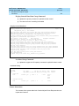
What’s New in DEFINITY®
Enterprise Communications Server
Release 8.2
Job Aid
555-233-754
Comcode 108678806
Issue 1
April 2000
Copyright 2000, Lucent Technologies
All Rights Reserved
Printed in U.S.A.
Notice
Every effort was made to ensure that the information in this book was
complete and accurate at the time of printing. However, information is
subject to change.
Your Responsibility for Your System’s Security
Toll fraud is the unauthorized use of your telecommunications system
by an unauthorized party, for example, persons other than your company’s employees, agents, subcontractors, or persons working on your
company’s behalf. Note that there may be a risk of toll fraud associated
with your telecommunications system and, if toll fraud occurs, it can
result in substantial additional charges for your telecommunications
services.
You and your system manager are responsible for the security of your
system, such as programming and configuring your equipment to prevent unauthorized use. The system manager is also responsible for
reading all installation, instruction, and system administration documents provided with this product in order to fully understand the features that can introduce risk of toll fraud and the steps that can be taken
to reduce that risk. Lucent Technologies does not warrant that this
product is immune from or will prevent unauthorized use of common-carrier telecommunication services or facilities accessed through
or connected to it. Lucent Technologies will not be responsible for any
charges that result from such unauthorized use.
Lucent Technologies Fraud Intervention
If you suspect that you are being victimized by toll fraud and you need
technical support or assistance, call Technical Service Center Toll
Fraud Intervention Hotline at 1 800 643-2353.
Federal Communications Commission Statement
Part 15: Class A Statement. This equipment has been tested and
found to comply with the limits for a Class A digital device, pursuant to
Part 15 of the FCC Rules. These limits are designed to provide reasonable protection against harmful interference when the equipment is
operated in a commercial environment. This equipment generates,
uses, and can radiate radio-frequency energy and, if not installed and
used in accordance with the instructions, may cause harmful interference to radio communications. Operation of this equipment in a residential area is likely to cause harmful interference, in which case the
user will be required to correct the interference at his own expense.
Part 68: Network Registration Number. This equipment is registered
with the FCC in accordance with Part 68 of the FCC Rules. It is identified by FCC registration number AS593M-13283-MF-E.
Part 68: Answer-Supervision Signaling. Allowing this equipment to
be operated in a manner that does not provide proper answer-supervision signaling is in violation of Part 68 Rules. This equipment returns
answer-supervision signals to the public switched network when:
• Answered by the called station
• Answered by the attendant
• Routed to a recorded announcement that can be administered by
the CPE user
This equipment returns answer-supervision signals on all DID calls
forwarded back to the public switched telephone network. Permissible
exceptions are:
• A call is unanswered
• A busy tone is received
• A reorder tone is received
Canadian Department of Communications (DOC)
Interference Information
This digital apparatus does not exceed the Class A limits for radio
noise emissions set out in the radio interference regulations of the
Canadian Department of Communications.
Le Présent Appareil Nomérique n’émet pas de bruits radioélectriques
dépassant les limites applicables aux appareils numériques de la class
A préscrites dans le reglement sur le brouillage radioélectrique édicté
par le ministére des Communications du Canada.
Trademarks
See the preface of this document.
Ordering Information
Call:
Lucent Technologies BCS Publications Center
Voice 1 800 457-1235 International Voice 317 322-6416
Fax 1 800 457-1764
International Fax 317 322-6699
Write:
Lucent Technologies BCS Publications Center
2855 N. Franklin Road
Indianapolis, IN 46219
Order:
Document No. 555-233-754
Comcode 108678806
Issue 1, April 2000
You can be placed on a standing order list for this and other documents
you may need. Standing order will enable you to automatically receive
updated versions of individual documents or document sets, billed to
account information that you provide. For more information on standing orders, or to be put on a list to receive future issues of this document, contact the Lucent Technologies Publications Center.
European Union Declaration of Conformity
The “CE” mark affixed to the DEFINITY® equipment described in
this book indicates that the equipment conforms to the following European Union (EU) Directives:
• Electromagnetic Compatibility (89/336/EEC)
• Low Voltage (73/23/EEC)
• Telecommunications Terminal Equipment (TTE) i-CTR3 BRI
and i-CTR4 PRI
For more information on standards compliance, contact your local distributor.
Comments
To comment on this document, return the comment card at the front of
the document.
Acknowledgment
This document was prepared by Product Documentation Development,
Lucent Technologies, Denver, CO.
Issue 1
April 2000
What’s New in DEFINITY ECS
Release 8.2 Job Aid 555-233-754
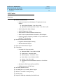
Contents
iii
Contents
Contents
iii
New Switch and Adjunct Support
1
About this Document
1
■
■
■
■
Overview
2
DEFINITY® Enterprise Communications Server
Release 8
2
Release 8.1 Feature List
3
Release 8.2 Feature List
5
Platform - Enhancements/Renewal
7
DADMIN LOGIN
7
Optical Drive (TN2211)
8
U.S. Analog Trunk & Line Circuit Pack TN797
14
TN2313 DS1 Interface (US (24-Channel) or
International (32-Channel))
14
24 Port Analog Line with Caller ID: TN793B
& TN2793B
15
General Telephony Enhancements - Global
16
Coverage of Calls Redirected Off-Net (CCRON)
16
13-Digit Authorization Codes
22
Auto Exclusion
25
64 Bridged Call Appearances
27
Circular Station Hunting
27
Group Call Pick-up
28
Long Hold Recall – Warning
28
Reset Shift Call
28
Station Self Display
28
Special Dial Tone [China]
28
6200 Analog Native Support
29
6400 Tip/Ring (Data Module Features)
34
Abort Transfer
43
Attendant Vectoring
45
Trouble Isolation: List Trace Command
55
NewHospitality-Related Features
62
Auto Selection Direct Inward Dial (DID) Numbers
62
Crisis Alert to Pager
65
Issue 1
April 2000
What’s New in DEFINITY ECS
Release 8.2 Job Aid 555-233-754
Contents
iv
Check In via the Hunt-To Feature
■
■
New Mobility-Related Features
73
X-Station Mobility (DECT)
73
XStation Mobility (MWL)
77
Telephony Applications - International
Reset Shift Call
■
70
Call Center
91
91
96
Overview
96
Call Center Release Control
98
Call Center - ASAI Trunk Group Identification
99
Call Center – ASAI/CTI Pending Work Mode
Changes
100
CALLMASTER V (Call Center 6416D+) Native
Support
101
Call Center - ASAI Capacity Increases for
Multiple Application Support
101
Call Center-Logged in Advocate Agent Counting
104
ATM_CMS
104
CMS High Availability
109
PC Application Software Translation Exchange
(PASTE) Update
111
Networking Enhancements
113
Networking - International
113
■
■
Continuous and Pulsed E&M Signaling (Brazil)
113
China Howler After Busy & Disconnect on No
Answer
118
Time Supervision & Force Release (China)
121
Administrable Loss Plan
125
Networking - ISDN Private
133
QSIG Call Independent Signaling Connection
(CISC) Enhancements
133
QSIG VALU Call Coverage
136
QSIG Integration: Transfer to Audix
141
QSIG CAS & VALU Coverage Interaction Support
144
QSIG CAS Enhancement
146
Centralized Voice Mail Via Mode Code
148
Support for Japan National Private Networking
154
Issue 1
April 2000
What’s New in DEFINITY ECS
Release 8.2 Job Aid 555-233-754
Contents
v
■
■
■
Networking - ISDN Public
155
BellCore Calling Name ID
155
Bellcore National ISDN Calling Name
Supplementary Service for PRI
156
Feature Plus – Non-DID Calling via UDP
160
Multiple Pubnet Calling/Connect Numbers/
System (Italy)
163
Pass Advice of Charge (AOC) to BRI Endpoints
172
Restricted Presentation
179
IP Solutions
186
TCP/IP-Connected Trunks
186
H.323 Trunk Administration
187
DEFINITY Internet Protocol (IP) Softphones
192
Adding a DEFINITY IP Softphone
196
IP Support Hardware
199
Networking - ATM
211
ATM Hardware
213
Administering ATM-CES amd ATM-PNC
214
Additional DEFINITY ECS administration
234
ATM PNC Reliability
244
Interworking with Bandwidth Constricted ATM
Networks
249
T1 401A/E1 402A/E1 403A Synchronization
Splitters
270
What’s New in DEFINITY ECS
Release 8.2 Job Aid 555-233-754
Issue 1
April 2000
Contents
vi
What’s New in DEFINITY ECS
Release 8.2 Job Aid 555-233-754
1
Issue 1
April 2000
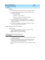
New Switch and Adjunct Support
1
New Switch and Adjunct Support
1
About this Document
This document introduces new and enhanced features and capabilities of
DEFINITY Enterprise Communications Server (ECS) Release 8. It does not
contain comprehensive instructions for switch administration or complete feature
descriptions, nor does it contain information about how to install, maintain, repair,
or troubleshoot the switch.
It is intended for DEFINITY system administrators and managers, users interested
in information about specific features, and Lucent Technologies personnel
responsible for planning, designing, configuring, selling, and supporting the
system.
This document assumes that you are familiar with DEFINITY ECS in a recent
release of DEFINITY ECS software.
What’s New in DEFINITY ECS
Release 8.2 Job Aid 555-233-754
1
Issue 1
April 2000
New Switch and Adjunct Support
Overview
Overview
DEFINITY® Enterprise Communications Server
Release 8
DEFINITY® ECS Release 8 is the next step in the evolution of the
DEFINITY® ECS.
■
It is a multi-purpose platform developed to support a number of offers.
■
It builds upon existing capabilities of the DEFINITY® ECS standard and
special development releases to implement cost reductions for Lucent
Technologies, and a new set of advanced capabilities for the global
communications marketplace.
■
Release 8 introduces these major features:
■
— Completion of C-LAN
— QSIG CAS enhancements
— ATM enhancements
— ASAI enhancements
— Call center enhancements
— IP Solutions
— Centralized Voice Mail via Mode Code
— Attendant Vectoring
Upgrades
Paths
R8 is an upgrade path for existing DEFINITY® system customers.
■
From pre-R5 to R8
■
From R5, R6, and R7 to R8 (through R5.5 for si customers with critical
reliability configurations)
■
Between specific R8 models
NOTE:
There are no upgrade paths for:
■
Non-csi models to csi models
■
Vs models to R8
2
What’s New in DEFINITY ECS
Release 8.2 Job Aid 555-233-754
1
New Switch and Adjunct Support
Overview
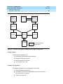
Release 8.1 Feature List
CCRON Renewal
De-admin Login
Abort Xfer
13 Digit Auth Codes
X-station Mobility
DECT Support
Message Waiting Enhancement
6400 Tip/Ring Data Module
QSIG CISC Enhancements
■
Status Signaling Group
QSIG VALU Enhancements
■
Call Coverage
■
Distinctive Alerting
■
Call Coverage and CAS
Feature + non DID via UDP
BCS/Guestworks Enhancement
■
Auto digit rotation for DID
■
Crisis Alert to Pager
■
Suite Check in Via Hunt To Feature
ISDN Bellcore call-ID
E&M Signaling Enhancements
■
Brazil Contin. E&M Signal
■
Brazil Pulsed E&M Signal
■
Hungary Signal
ATM Network Duplication
6200 Analog Native Support
GTS Restricted Presentation
Australian CIN Board Support
Italy Multi Pub Net Calling – Connect Number/System
Pass AOC to BRI Endpoints
China Special Dial Tone
Issue 1
April 2000
3
What’s New in DEFINITY ECS
Release 8.2 Job Aid 555-233-754
1
New Switch and Adjunct Support
Overview
China Outgoing Call No Answer
China Time Super. and Force Release
Auto Exclusion by COS
INS l500-AOC
Fast Analog Modem Support Testing
Enhanced Terminal Parameters
G3R EMC Compliance
TN746B Buffer FW Changes
Advocate Enhancements
■
Logged-in Agent Counting
■
Standard Reports
ASAI/CTI Enhancements
■
CTI Regression Testing
■
Pending Work Mode Changes
■
Switch SW Version Query
■
Trunk Group ID in Event Reports
■
Cap Increase - Active Route Requirements
■
Cap Increase - Split Skill Dom Ctrl
■
UUI>32byte
Interworking Bandconstr (ATM)
ACD/ATM Capacity Increases
■
Hunt Group Members
■
Hunt Groups
■
Measure VDNs
■
QueueS1ots
■
Vectors
■
1000 Announcements
CMS ATM Trk Measurements
Site Stats Remote EPN
Call Master V Native Support
CMS High Avail. Support
Call Center Release Control
TN802B (Medpro)
Issue 1
April 2000
4
What’s New in DEFINITY ECS
Release 8.2 Job Aid 555-233-754
1
New Switch and Adjunct Support
Overview
TN799B
■
Variable Length Pin
■
TraceRoute
■
Packet Error History
■
SNMP Re-arch
■
Host Route Admin Chan Cs
TN2211 Optical Drive
■
UN332C MSSNET
Release 8.2 Feature List
IP Solutions
■
IP SoftPhones
■
H.323 Trunks
ATM PNC Reliability
QSIG Integration: Transfer to Audix
Attendant Vectoring (formerly CAS)
QSIG CAS & VALU Coverage Interaction Support
QSIG CAS Enhancement
■
Attendant Display of COR
■
Attendant Return of Call
■
Display Enhancements
■
Priority Queue
■
RLT Emulation via PRI
Support for Japan National Private Networking
■
2MB Trunk — Ph 2: Codeset 5 TCMs
■
2MB Trunk — Ph 2: Connect Ack
■
2MB Trunk — Ph 2: Different Protocol Discriminator
■
D Channel — Private ISDN Networks — Q.931.a, Q.932.a
■
D Channel — Private ISDN Networks — 951.a
Administrable Loss Plan
24 Port Analog Line with Caller ID (TN793/TN2793B)
U.S. Analog Trunk & Line Board (TN797) without Busy Tone Detection
Issue 1
April 2000
5
What’s New in DEFINITY ECS
Release 8.2 Job Aid 555-233-754
1
New Switch and Adjunct Support
Overview
Centralized Voice Mail via Interswitch Mode Code
Trouble Isolation: List Trace Command
TN2313
T1 401A Sync Splitter
E1 402A Sync Splitter
E1 403A Sync Spllitter
Issue 1
April 2000
6
Issue 1
April 2000
What’s New in DEFINITY ECS
Release 8.2 Job Aid 555-233-754
1
New Switch and Adjunct Support
Platform - Enhancements/Renewal
7
Platform - Enhancements/Renewal
DADMIN LOGIN
■
Administration of the dadmin login uses the standard DEFINITY® login and
permission form interfaces.
■
Dadmin Login replaces Inads Login for Distributors.
■
The dadmin login ID, restricts access to commands that are limited to
Lucent Services.
■
The dadmin login service level is located between the inads and craft
logins service levels in the system administration/maintenance login
permission hierarchy.
Restart Strategy for Dadmin Login
■
Login administration parameters are retained for the dadmin login on
recovery level 1 (warm) and recovery level 2 (cold) restarts and require
retrieval from a translation storage device for all other restart levels.
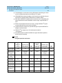
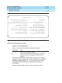
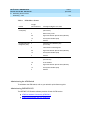
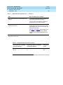
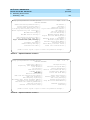
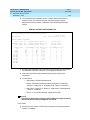
Number of Logins
Platform
Maximum Number of
Login Distribution
Logins *
R8(vs/si/csi)
R8(r)
16
25
■
4 Lucent Services Logins
■
1 Dadmin Login
■
11 Customer Logins
■
4 Lucent Services Logins
■
1 Dadmin Login
■
20 Customer Logins
*The maximum number of logins does not include the “mis” login which is used
internally by the system to establish connections to call management systems,
CMS.
What’s New in DEFINITY ECS
Release 8.2 Job Aid 555-233-754
1
Issue 1
April 2000
New Switch and Adjunct Support
Platform - Enhancements/Renewal
8
Feature to Feature Interactions
Access Security Gateway (ASG)
■
ASG authentication not required by default for the dadmin login.
■
ASG field on the dadmin login form defaults to n(o) and all fields that
appear on the Access Security Gateway page of the login form are
unassigned or set to system defaults.
■
Secret Key field is not defaulted for the dadmin login.
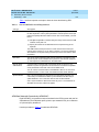
Constraints and Limitations
■
The number of logins supported for various system configurations is
increased by one to accommodate the addition of the “dadmin” login.
Customer Options
■
Administration of Version and Location fields remain under “init” control on
the System Parameters Customer Options forms.
Offer Categorization
■
Administration remains under the control of the init login.
Enable/Disable Login
■
The system supports execution of the enable and disable login commands
for the dadmin login.
■
Permission to execute these commands for the dadmin login is restricted to
the init and dadmin logins, and to the inads login, if it has been
administered to have “Administer Permissions” permissions.
■
It is possible for the dadmin login to disable itself by executing the disable
login dadmin command.
■
Execution of the command will not terminate the current login session,
however, subsequent attempts to log in to the system using the dadmin
login will be denied.
■
Re-enabling the dadmin login must be performed by the init login or the
inads login, if it has been administered to have “Administer Permissions”.
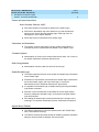
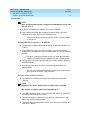
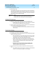
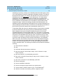
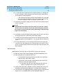
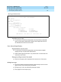
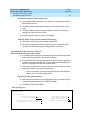
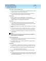
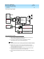
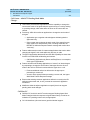
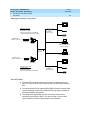
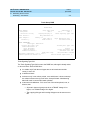
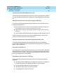
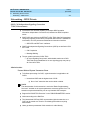
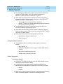
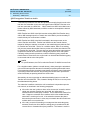
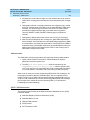
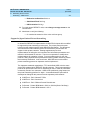
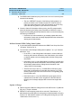
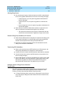
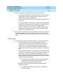
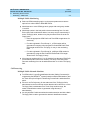
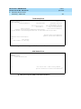
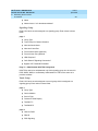
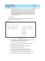
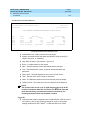
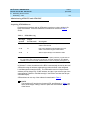
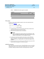
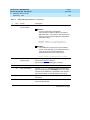
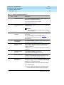
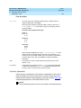
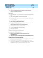
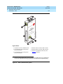
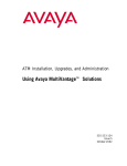
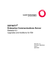
Optical Drive (TN2211)
■
The TN2211 Optical Drive is a direct replacement for the TN1656 Tape
Drive, and offers the following:
■
The TN2211 provides removable storage for software upgrades, translation
backups, announcement file backups, and core dumps
What’s New in DEFINITY ECS
Release 8.2 Job Aid 555-233-754
1
Issue 1
April 2000
New Switch and Adjunct Support
Platform - Enhancements/Renewal
■
The TN2211 Optical Drive resolves several problems related to the tape
drive such as availability, cost, performance, reliability, and storage
capacity.
■
The TN2211 is designed to be less expensive and more reliable than the
TN1656.
■
Installation and Upgrade procedures for the TN2211 optical drive are
nearly the same as for the TN1656 tape drive.
■
The tape commands are replaced by removable-media commands.
— test tape becomes test removable-media, or test rem for the
shorthand version.
■
An optical drive is faster than a tape drive, but it is not related to call flow.
— A full backup to an optical disk cartridge takes approximately 20
minutes, compared to about 95 minutes for a tape.
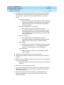
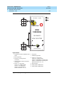
Figure 1.
Optical Drive (TN2211)
9
What’s New in DEFINITY ECS
Release 8.2 Job Aid 555-233-754
1
Issue 1
April 2000
New Switch and Adjunct Support
Platform - Enhancements/Renewal
10
Configuration
■
The configuration is a G3r switch (simplex or duplex) with a TN2211 Optical
Drive and a UN332C MSSNET OR a TN1656 Tape Drive and a UN332B
MSSNET.
■
All commands using tape are replaced by removable-media.
■
Commands such as test tape, busy tape, release tape, etc. are replaced by
removable-media.
— The commands are test removable-media, busy removable-media,
etc. removable-media can be shortened to rem (test rem, busy rem).
■
If a user enters tape instead of removable-media, the error/help message
“tape is no longer valid; use removable-media” is displayed on the SAT.
■
All instances of tape on output displays are replaced with removable-media
or R-MEDIA as appropriate.
■
Both the tape drive and optical drive are supported by R8 software.
■
G3r switches running R8 software are shipped with the TN2211 Optical
Drive and the UN332C MSSNET
— New switches are shipped with the TN1656 Tape Drive and
hardware
■
The UN332C MSSNET must be used with the TN2211 Optical Drive.
NOTE:
UN332C MSSNET is backward-compatible with the UN332B. UN332C
will work with a tape drive.
Serviceability
■
A (remote) maintenance user can identify between the two drive types by
using the list config command to determine the TN code.
■
The tape commands are replaced with removable-media commands (rem
for short).
■
A user can verify the correct suffix of the UN332C by reading the circuit
pack label or reading the output from the list configuration control
command.
■
Typically, a defective tape drive will be replaced with another tape drive for
existing systems.
■
Customers are not required to upgrade the tape drive to an optical drive for
bugfix.
■
For “purchased” upgrades to R8, the customer will are required to upgrade
to the TN2211 optical drive and UN332C MSSNET.
Upgrades
What’s New in DEFINITY ECS
Release 8.2 Job Aid 555-233-754
1
Issue 1
April 2000
New Switch and Adjunct Support
Platform - Enhancements/Renewal
■
The procedure to both upgrade from pre-R8 to R8 and to change from a
TN1656 to a TN2211 at the same time is not supported.
■
Services must upgrade the hardware first (TN1656 to a TN2211 and a
UN332B to a UN332C), then upgrade to the R8 software.
11
— The hardware must be upgraded prior to the software.
■
■
This will take advantage of the faster optical drive technology
for some of the upgrade steps.
■
This does not require that the new software be shipped on
two different media forms (tape and optical disk cartridge).
Replacement of the tape drive with the optical drive does not impact the
call preserving nature of the upgrade.
Issue 1
April 2000
What’s New in DEFINITY ECS
Release 8.2 Job Aid 555-233-754
1
New Switch and Adjunct Support
Platform - Enhancements/Renewal
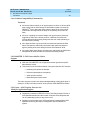
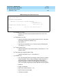
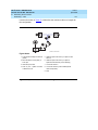
12
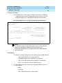
Optical Drive Cartridge
What’s New in DEFINITY ECS
Release 8.2 Job Aid 555-233-754
1
Issue 1
April 2000
New Switch and Adjunct Support
Platform - Enhancements/Renewal
13
Maintenance
NOTE:
Refer to Definity ECS Release 8.2 Upgrades and Additions for R8r, 555233-115, Issue 1.
■
A TN2211 is maintained in software as if it were a TN1656.
■
After inserting an optical disk cartridge, the access lamp of the drive
should be on for a few seconds, then should turn off.
— Access lamp blinking afterwards typically means a cartridge should
be reinserted.
Maintenance Object appears as “R-MEDIA”
■
The Maintenance Object appears as R-MEDIA for either the TN1656 or the
TN2211.
■
This Maintenance Object is used in the output of commands such as
display alarms, display errors, test removable-media, etc., and functions as
follows:
— If an error or alarm log contains an entry for TAPE, the description
changes to R-MEDIA after the software has been upgraded to R8.
■
The list config command output describes the TN1656 and the TN2211 as
R-MEDIA DRIVE.
■
Both the tape and optical drives are now generically described as RMEDIA DRIVE.
— The only way to differentiate between the two drives in R8 is to look
at the TN code via the list config command.
No limit on the number of accesses
■
The software is not limited the number of accesses of an optical disk
cartridge.
NOTE:
Important! The TN2211 Optical Drive does NOT require cleaning.
Any attempt to clean the optical drive will damage it.
■
The LMM will display TAPE on boot-up on the SAT, even if an optical drive
and optical disk cartridge are present.
■
In duplicated systems, either carrier may have an optical drive or a tape
drive, since software supports both.
■
The drives can be mixed between carriers (one carrier has a TN1656, the
other has a TN2211).
What’s New in DEFINITY ECS
Release 8.2 Job Aid 555-233-754
1
Issue 1
April 2000
New Switch and Adjunct Support
Platform - Enhancements/Renewal
14
U.S. Analog Trunk & Line Circuit Pack TN797
Description
This circuit pack is the combination 8-port Analog Trunk and Line Circuit Pack,
TN797, for the US, Canada, and like countries. This provides the user with the
capability to administer any of the 8 ports of this analog circuit pack as a:
■
Central Office trunk, either loop start or ground start,
■
CAMA E911 trunk,
■
Direct Inward Dialing trunk, either wink start or immediate start; or
■
An analog line, on or off-premises, with or without LED message waiting
indication.
One way of visualizing the capabilities of this circuit pack is to think that when a
port is administered as a CO trunk, its capabilities will be similar to those of a port
of the analog CO trunk TN747B (or the TN429D used for CAMA/E911); if the port
is administered as a DID trunk, its capabilities will be similar to those of the DID
trunk TN753B, and if administered as a line circuit, its capabilities will be similar
to those of the analog line TN746B.
Note that the TN797 circuit pack does not support ICLID on the analog trunk to
the CO, nor Caller ID on the line side to a terminal. Additional capabilities,
including additional international features, are being planned for a future release
of this circuit pack.
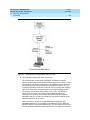
One interesting application of this circuit pack is to provide Emergency Transfer
capabilities to a system which has only DS1 connectivity to the central office, or
to one that has only digital terminals. This circuit pack will permit analog
connectivity to the central office from analog terminals using only one port slot.
There are no changes required in Call Processing for this circuit pack.
The TN797 circuit pack supports all analog terminals supported by the similar
analog circuit packs mentioned above. However, neon lamp message waiting
indication is not supported by this circuit pack.
TN2313 DS1 Interface (US (24-Channel) or
International (32-Channel))
The TN2313 DS1 port board interfaces a DS1 trunk to the switch backplane via
port slots that are standard for DEFINITY products. The TN2313 is compatible
with previous DS1 circuit packs, including the TN464F (V19 and below), the
TN2464 (V19 and below), and the TN767E DS1, except that it does not provide
for packet adjunct capabilities. The TN2313 supports a variety of applications,
including networking of DEFINITY switches, international trunk types, video
teleconferencing, and wideband data transmission.
Issue 1
April 2000
What’s New in DEFINITY ECS
Release 8.2 Job Aid 555-233-754
1
New Switch and Adjunct Support
Platform - Enhancements/Renewal
15
The TN2313 DS1 interface can be configured for domestic (24-channel, 1.544
Mbps) or international (32-channel, 2.048 Mbps) use. The TN2313 can supply two
8-Khz reference signals to the switch backplane for optional use by the tone/clock
board in synchronizing the system clock to the received line clock.
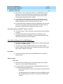
24 Port Analog Line with Caller ID: TN793B
& TN2793B
The TN793/TN793B is a dual coded, analog line 24-port, that performs all the functions of
the TN746B, 16-port analog line circuit pack. Each port supports 1 voice terminal, such as
500 (rotary dial) and 2500 terminals (DTMF dial).
The TN793/TN793B supports on-premises (in-building) wiring with either touch-tone or
rotary dialing and with or without the LED and neon Message Waiting Indicators. The
TN793/TN793B supports off-premises wiring (out-of-building only with certified protection
equipment) with either DTMF or rotary dialing, but LED or neon message waiting indicators
are not supported off -premises.
The TN793/TN793B, along with a TN755B neon power unit per carrier or per single-carrier
cabinet, supports voice terminals equipped with neon message waiting indicators (onpremises use only). The TN793/TN793B supports 3 ringer loads, only 1 voice terminal can
have an LED or neon message waiting indicator. The TN793/TN793B allows a maximum of
12 simultaneous ports ringing.
The TN793/TN793B supports A-Law and µ-law companding and administrable timers. The
TN793 supports queue warning level lights associated with the DDC and UCD features,
recorded announcements associated with the Intercept Treatment feature, and PagePac
paging system for the Loudspeaker Paging feature. Additional support is provided for
external alerting devices associated with the TAAS feature, neon message waiting
indicators, and modems The TN793/TN793B also supports secondary lightning protection.
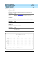
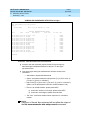
The TN793B is compatible with the terminal configurations shown in the table below.
Table 1.
Terminals and wiring configurations supported by the TN793
Terminal
Wire Size
Maximum Range
500-Type
24 AWG (0.2 mm2/0.5 mm)
20,000 ft (6,096 m)
2500-Type
24 AWG (0.2 mm2/0.5 mm)
20,000 ft (6,096 m)
6200-Type
2/0.5
mm)
12,000 ft. (3,657m)
2/0.5
24 AWG (0.2 mm
7100-Series
24 AWG (0.2 mm
mm)
20,000 ft. (6,096 m)
8100-Series
24 AWG (0.2 mm2/0.5 mm)
12,000 ft. (3,657m)
9100-Series
2/0.5
24 AWG (0.2 mm
mm)
12,000 ft. (3,657m)
What’s New in DEFINITY ECS
Release 8.2 Job Aid 555-233-754
1
Issue 1
April 2000
New Switch and Adjunct Support
General Telephony Enhancements - Global
16
General Telephony Enhancements Global
Coverage of Calls Redirected Off-Net (CCRON)
Release 8 Enhancements
■
Remote SAC Activation/Deactivation Call Processing
■
Threshold Activated CF Timer Call Processing
■
Coverage After Forward (per station) Call Processing
■
ISDN Renewal(long term)
■
Maintain SBA at Principal Call Processing
Remote Send All Calls(SAC) Activation/
Deactivation
■
The Remote Send All Calls Activation/Deactivation feature allows a remote
user to activate or deactivate send all calls.
Remote SAC Activation/Deactivation
■
New Feature Access Codes
■
Added to the Feature Access Codes (FAC) form.
— These new feature access codes, followed by the user’s extension,
“#,” associated Station Security Code (SSC) and “#,” are used to
activate/deactivate Send All Calls (SAC) for the specified extension
from any on-site extension or remotely (offnet).
— Activating/Deactivating SAC Via The Remote SAC Feature Access
Code Or Existing Method Activating or deactivating SAC via either
the Remote SAC feature access codes or existing SAC button or
feature access codes have the same effect.
— SAC may be activated by using a local SAC FAC, SAC feature
button, or by activating Remote SAC.
— SAC may be inactivated by using a local SAC FAC, SAC feature
button, or by activating Remote SAC.
Issue 1
April 2000
What’s New in DEFINITY ECS
Release 8.2 Job Aid 555-233-754
1
New Switch and Adjunct Support
General Telephony Enhancements - Global
17
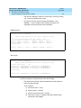
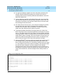
Remote SAC Activation/Deactivation Form
■
Added New “Remote Send All Calls Activation:” and “Deactivation:” Fields
on the FEATURE ACCESS CODE (FAC) Form
— FACs allow a remote user to activate or deactivate the Send All Calls
feature.
— Feature access codes may be 1 to 4 digits; * and # may be used as
the first digit only. The defaults are blank.
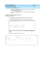
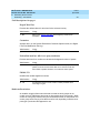
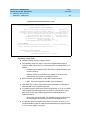
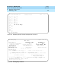
Feature Access Code (FAC) Form (page 3 of x)
change feature-access-codes
Page 3 of X
FEATURE ACCESS CODE (FAC)
Program Access Code:
Refresh Terminal Parameters Access Code:
Remote Send All Calls Activation:
Send All Calls Activation:
Station Security Code Change Access Code:
Terminal Dial-up Test Access Code:
Terminal Translation Initialization Merge Code:
Transfer to AUDIX Access Code:
Trunk Answer Any Station Access Code:
User Control Restrict Activation:
Voice Coverage Message Retrieval Access Code:
Voice Principal Message Retrieval Access Code:
Whisper Page Activation Access Code:
____
____
____
Deactivation:
____
Deactivation:
____
____
____ Separation Code:
____
____
____
Deactivation:
____
____
____
____
____
____
____
‘#’ as Abbreviation for Extension of Currently
Active Appearance
■
For either of the new feature access codes, a ‘#’ dialed directly after the
feature access code will signify that the extension of the appearance being
dialed from is the extension being administered, and the extension need
not be dialed; i.e., the initial ‘#’ is followed by the Station Security Code, ‘#’.
Remote User
■
Access this feature by dialing the telecommuting access extension
telephone number directly or by being transferred to it.
— Alternatively, the remote user can dial the remote access extension.
■
On receipt of system dial tone the user would enter the appropriate FAC
(either activate or deactivate SAC).
What’s New in DEFINITY ECS
Release 8.2 Job Aid 555-233-754
1
Issue 1
April 2000
New Switch and Adjunct Support
General Telephony Enhancements - Global
18
■
The user then dials the station extension number, followed by a “#” and
station security code (SSC), followed by a “#.”
■
The Remote SAC Activation/Deactivation feature can also be activated by
a local user from any local extension.
■
The local user would access this feature on receipt of dial tone by entering
the appropriate FAC (either activate or deactivate SAC) and receive recall
dial tone.
■
The user then dials the station extension number, followed by a “#” and
station security code, followed by a “#.”
■
If the user is dialing from the extension which is to be administered, the
user may enter just the ‘#’ followed by the SSC, followed by “#,” this will
signify to the system that the extension number of the appearance being
dialed from is the extension number being administered.
■
Then either confirmation or intercept tone is returned if any of the following
conditions exist:
Local User
— The extension number entered is invalid (logged as an invalid
attempt).
— The extension number is not accessible from the user’s partition.
— The SSC is invalid for the extension entered (logged as an invalid
attempt).
— Interdigit time out has occurred.
■
If activation/deactivation is successful, then confirmation tone is returned
and SAC is either activated or deactivated at this point.
ISDN Renewal (Interworking Assumption)
When CCRON calls are extended over ISDN facilities, two scenarios are possible.
1. ISDN end-to-end facilities are established
Or
2. ISDN end-to-end facilities are not available; a portion of the connection is
not ISDN and ISDN facilities interworking is required for some link between
endpoints.
■
ISDN end-to-end was assumed for a period of time, after which
interworking was assumed unless a positive indication from the ISDN
network signaled otherwise.
Issue 1
April 2000
What’s New in DEFINITY ECS
Release 8.2 Job Aid 555-233-754
1
New Switch and Adjunct Support
General Telephony Enhancements - Global
19
Off-Net Coverage Points
■
Any point in a principal’s coverage path can be administered as an off-net
destination.
NOTE:
Time-of-Day Coverage feature increases the number of coverage
points from 3 to 6.
Increase Number of Remote Coverage Points
■
Number of Remote Coverage Points available (on all platforms) increased
from 225 to 999.
Increase Number of Coverage Paths
■
Number of coverage paths increased from 600 to 999 on the small mips
and from to 7500 to 9999 on the large mips.
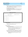
New System Parameters--Call Coverage / Call Forwarding Form, Page 1
change system-parameters coverage-forwarding
Page 1 of 2
SYSTEM PARAMETERS -- CALL COVERAGE / CALL FORWARDING
CALL COVERAGE/FORWARDING PARAMETERS
Local Cvg Subsequent Redirection/CFWD No Ans Interval (rings):
Off-Net Cvg Subsequent Redirection/CFWD No Ans Interval (rings):
Coverage - Caller Response Interval (seconds):
Threshold for Blocking Off-Net Redirection of Incoming Trunks Calls:
_
_
_
1
COVERAGE
Keep Held SBA at Coverage Point?
External Coverage Treatment for Transferred Incoming Calls?
Immediate Redirection on Receipt of PROGRESS Inband Information?
Maintain SBA At Principal?
QSIG VALU Coverage Overrides QSIG Diversion with Rerouting?
Station Hunt Before Coverage?
_
_
_
_
_
n
FORWARDING
Call Forward Override? _
Coverage After Forwarding? _
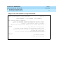
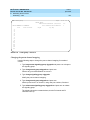
New System Parameters--Call Coverage / Call Forwarding Form, Page 2 CCRON
Enabled
change system-parameters coverage-forwarding
SYSTEM PARAMETERS -- CALL COVERAGE / CALL FORWARDING
Page 2 of 2
COVERAGE OF CALLS REDIRECTED OFF-NET (CCRON)
Coverage Of Calls Redirected Off-Net Enabled?
Activate Answer Detection (Preserves SBA) On Final CCRON Cvg Point?
Ignore Network Answer Supervision?
Disable call classifier for CCRON over ISDN trunks?
y
y
y
n
Issue 1
April 2000
What’s New in DEFINITY ECS
Release 8.2 Job Aid 555-233-754
1
New Switch and Adjunct Support
General Telephony Enhancements - Global
20
New System Parameters--Call Coverage / Call Forwarding Form, Page 2 CCRON
Disabled
change system-parameters coverage-forwarding
SYSTEM PARAMETERS -- CALL COVERAGE / CALL FORWARDING
Page 2 of 2
COVERAGE OF CALLS REDIRECTED OFF-NET (CCRON)
Coverage Of Calls Redirected Off-Net Enabled? N
Threshold Activated Call Forward Timer
■
Activates “Threshold for Blocking Off-Net Redirection of Incoming Trunk
Calls” field for Release 8.
■
Field has a range of 1-7 and “n”.
— “n” will mean that call processing never activates the Call Forward
timer
■
An infinite number of calls to a principal may be redirected
off-net.
— The default is 1, which provides the current operation.
— When a customer is upgraded from a release prior to R8, this field is
set to 1.
■
All incoming trunk calls to a particular station are blocked from redirecting
offnet during the call forward timer interval.
■
The R8.1 user can change this value.
Coverage After Forward (Station Option)
■
Adds a new field entitled “Coverage After Forwarding (station specific)?” to
page 2 of the Station form for all stations.
■
The field may contain any of three different values:
— y - indicates, that for this station, coverage treatment should be
applied after forwarding, regardless of the value of the “Coverage
After Forwarding?” field on the SYSTEM PARAMETERS - CALL
COVERAGE / CALL FORWARDING form
— n - indicates, that for this station, coverage treatment should not be
applied after forwarding., regardless of the value of the “Coverage
After Forwarding?” field on the SYSTEM PARAMETERS - CALL
COVERAGE / CALL FORWARDING form.
— default - indicates, that for this station, use the value of the
“Coverage After Forwarding?” field on the SYSTEM PARAMETERS
- CALL COVERAGE / CALL FORWARDING form.
Issue 1
April 2000
What’s New in DEFINITY ECS
Release 8.2 Job Aid 555-233-754
1
New Switch and Adjunct Support
General Telephony Enhancements - Global
21
NOTE:
Application of coverage treatment does not guarantee that the call will
definitely redirect to a coverage point, since the coverage criteria as
applied at the forwarded-to destination may not be satisfied.
■
When a DEFINITY® system with CCRON activated is upgraded to R8, the
value “s” (for ‘system’) set in the “Coverage After Forwarding ?” field on the
Station form for all stations
■
When a customer is upgraded from a release prior to R8, this field is set to
“s” for all stations, indicating that call processing uses the value on the
Coverage After Forwarding field on the SYSTEM PARAMETERS--CALL
COVERAGE / CALL FORWARDING form.
■
To override the system-wide parameter for a given station, the system
administrator must set the field on the Station form.
Station Form (Page 2 of X)
add station 1014
Page 2 of X
STATION
FEATURE OPTIONS
LWC Reception?
LWC Activation?
LWC Log External Calls?
CDR Privacy?
Redirect Notification?
Per Button Ring Control?
Bridged Call Alerting?
Active Station Ringing:
msa-spe
y
n
n
y
n
n
single
Auto Select Any Idle Appearance?
Coverage Msg Retrieval?
Auto Answer:
Data Restriction?
Idle Appearance Preference?
n
y
none
n
n
Restrict Last Appearance? y
H.320 Conversion? n
MWI Served User Type: ______
AUDIX Name:
Messaging Server Name: ______
Recall Rotary Digit? n
Per Station CPN - Send Calling Number?
Special Character for Restricted Number?
Display Client Redirection?
Select Last Used Appearance?
Coverage After Forwarding?
Multimedia Early Answer?
_
n
n
n
_
n
Maintain SBA at Principal
■
Allows customers to prevent the appropriation of a call appearance button
on the principal’s phone by the simulated bridge appearance by a coverage
call.
— The ability to take phone calls may be more important than the
capability of the principal to retrieve calls that have already
redirected to coverage.
What’s New in DEFINITY ECS
Release 8.2 Job Aid 555-233-754
1
Issue 1
April 2000
New Switch and Adjunct Support
General Telephony Enhancements - Global
22
Option to Dispense with Call Classifier On
Coverage Call
■
Established a new field, “Maintain SBA At Principal?”
■
This is a y/n field.
■
The default is y, which maintains current operation.
■
When a customer is upgraded from a release prior to R8, this field is set to
y.
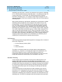
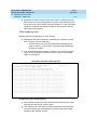
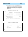
13-Digit Authorization Codes
■
The system now supports authorization codes from a minimum of 4 digits
to a maximum of 13 digits in length.
— The number of authorization codes allowed (90,000 in a G3r, 5,000
in a G3i) (not changed).
■
The user may have to dial up to 13 digits to enter an authorization code.
■
The use of the authorization code information for ARS, AAR, incoming
trunk authorization, remote access, or any other feature that may require
the collection of an authorization code has not changed.
■
If a standard CDR format is used and there are more than 7 digits in an
authorization code, the authorization code is truncated to the high 7 digits
to fit the format.
■
The customized format supports 13-digit authorization codes, and is
encouraged for those with larger authorization codes.
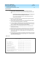
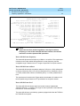
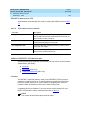
Feature Administration
■
Feature Administration allows the length of the authorization code assigned
on the system - parameters features form to be from 4 to 13 digits.
■
The security violations status form has changed to allow 13-digit
authorization codes.
■
The Authorization Code form shows 4 columns of 16 authorization codes
instead of 6 columns.
Issue 1
April 2000
What’s New in DEFINITY ECS
Release 8.2 Job Aid 555-233-754
1
New Switch and Adjunct Support
General Telephony Enhancements - Global
23
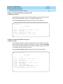
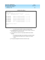
OLD SCREEN
monitor security-violations authorization-code
SECURITY VIOLATIONS STATUS
Date: 17:51 MON SEP 28 1999
AUTHORIZATION CODE VIOLATIONS
Date Time Originator Auth-Cd
09/28 17:19 Trunk 9639632 1 1
09/28 17:10 Trunk 8998989 1 1
TG No
Mbr Bar-Cd
Ext
CLI/ANI
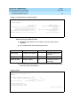
NEW SCREEN
SECURITY VIOLATIONS STATUS
Date: 17:51 MON SEP 28 1999
AUTHORIZATION CODE VIOLATIONS
Date Time Originator Auth-Cd TG/Mbr Bar-Cd
09/28 17:19 Trunk 9639632123456 1/ 1
09/28 17:10 Trunk 8998989123456 1/ 1
Ext
CLI/ANI
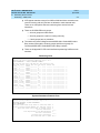
list authorization-code
LIST AUTHORIZATION CODES REPORT
Authorization
0000000000000
1111111111111
2222222222222
3333333333333
Code Class of Restriction(COR)
0
1
2
3
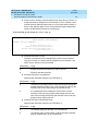
Call Detail Recording (CDR) Formatting
NOTE:
CDR formats are “standards” therefore no attempt was made to modify
them to fit larger authorization codes.
A customized CDR format handles 13-digit authorization codes and
allows any format to be created.
■
The form for translating authorization codes has changed to fit the new
maximum length.
Issue 1
April 2000
What’s New in DEFINITY ECS
Release 8.2 Job Aid 555-233-754
1
New Switch and Adjunct Support
General Telephony Enhancements - Global
24
— The new form displays a maximum of 48 codes (3 columns), leaving
only 1 column for adding more codes.
— To enter more codes, execute change authorization - code
9999999.... to show a blank screen, allowing 64 codes to be
submitted at one time rather than the original 96.
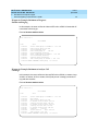
Original screen
change authorization-code 1111111 Page 1 of 1
Authorization Code - COR Mapping
NOTE: 96 codes administered. Use ’list’ to display all codes
AC COR
AC COR AC COR AC COR
AC
COR AC
COR
1111111 1 2222222 2 3333333 3 4444444 4 5555555 5 6666666 6
1111112 1 2222223 2 3333334 3
4444445 4 5555556 5 6666667 6
1111113 1 2222224 2 3333335 3
4444446 4 5555557 5 6666668 6
. (12 more rows)
.
.
1111125 1 2222236 2 3333347 3 4444458 4 5555569 5 6666680 6
New screen
change authorization-code 1111111111111 Page 1 of 1
Authorization Code - COR Mapping
NOTE: 64 codes administered. Use ’list’ to display all codes
AC COR AC COR AC COR AC
COR
1111111111111 1 2222222222222 2
1111111111112 1 2222222222223 2
1111111111113 1 2222222222224 2
(12 more rows)
.
.
1111111111125 1 2222222222236 2
■
3333333333333 3 4444444444444 4
3333333333334 3 4444444444445 4
3333333333335 3 4444444444446 4
3333333333347 3 4444444444458 4
If using both authorization codes and account codes, be aware that there is
a problem with phone calls that involve more than 36 digits.
— The length of the account code and authorization code should not
have more than 36 digits.
As an example:
■
ars access code = 1 digit
■
phone number = 15 digits
■
account code access code = 3 digits
■
This leaves a total of 17 digits for the total of authorization
and account code lengths.
Issue 1
April 2000
What’s New in DEFINITY ECS
Release 8.2 Job Aid 555-233-754
1
New Switch and Adjunct Support
General Telephony Enhancements - Global
25
Auto Exclusion
■
When Privacy - Manual Exclusion is activated, all other users with
appearances of an extension are prevented from bridging onto the active
call.
— If the Exclusion button is pressed while other users are bridged onto
the call, the other users are dropped from the call.
— The only way to activate Exclusion is by pressing the Exclusion
button on a per-call basis.
■
Exclusion is deactivated when the Exclusion button is pressed a second
time, or when the call is terminated.
■
Under R8 with Automatic Exclusion active, the Manual Exclusion feature
can now be automatically activated on a COS basis.
■
If a user is assigned a COS which has the Automatic Exclusion option set
to y, then Exclusion will automatically be activated when the user goes off
hook on a station which has an Exclusion button assigned.
■
Manual Exclusion can be activated while active on a call and it can be
activated before dialing.
■
Manual Exclusion still cannot be activated while the user is idle (onhook).
■
Under R8 with Automatic Exclusion active, a held exclusion call can be
unheld by any station with a bridged appearance of the appearance that
put the call on hold.
■
Automatic Exclusion will NOT be automatically activated when the principal
(or a bridged appearance of the principal) bridges onto a call that has been
answered by a coverage point.
COS screen
change cos
Page 1 of 1
CLASS OF SERVICE
0 1 2 3 4 5 6 7 8 9 10 11 12 13 14 15
Auto Callback
Call Fwd-All Calls
Data Privacy
Priority Calling
Console Permissions
Off-hook Alert
Client Room
Restrict Call Fwd-Off Net
Call Forward Busy/DA
Personal Station Access
Extended Forwarding All
Extended Forwarding B/DA
Trk-to-Trk Restriction Override
QSIG Call Offer Originations
Automatic Exclusion
n
n
n
n
n
n
n
n
n
n
n
n
n
n
n
y
y
y
y
n
n
n
y
n
n
n
n
n
n
n
y
n
n
n
n
n
n
y
n
n
n
n
n
n
n
n
y
n
n
n
n
n
y
n
n
n
n
n
n
n
y
y
n
n
n
n
n
y
n
n
n
n
n
n
n
n
n
y
n
n
n
n
y
n
n
n
n
n
n
n
y
n
y
n
n
n
n
y
n
n
n
n
n
n
n
n
y
y
n
n
n
n
y
n
n
n
n
n
n
n
y
y
y
n
n
n
n
y
n
n
n
n
n
n
n
n
n
n
y
n
n
n
y
n
n
n
n
n
n
n
y
n
n
y
n
n
n
y
n
n
n
n
n
n
n
n
y
n
y
n
n
n
y
n
n
n
n
n
n
n
y
y
n
y
n
n
n
y
n
n
n
n
n
n
n
n
n
y
y
n
n
n
y
n
n
n
n
n
n
n
y
n
y
y
n
n
n
y
n
n
n
n
n
n
n
n
y
y
y
n
n
n
y
n
n
n
n
n
n
n
Issue 1
April 2000
What’s New in DEFINITY ECS
Release 8.2 Job Aid 555-233-754
1
New Switch and Adjunct Support
General Telephony Enhancements - Global
■
26
Allows a user to activate automatically Exclusion when they go off hook on
a station that has an assigned EXCLUSION button. If set to n, allows a user
manual exclusion when they press the EXCLUSION button before dialing or
during a call. Appears when, on the Feature-Related System Parameters
screen, the Automatic Exclusion by COS field is y.
Feature-Related System Parameters screen - Page 10
change system-parameters features
FEATURE-RELATED SYSTEM PARAMETERS
Page 10 of 10
AUTOMATIC EXCLUSION PARAMETERS
Automatic Exclusion by COS?
Automatic Exclusion Coverage/Hold?
Automatic Exclusion with Whisper Page?
Recall Rotary Digit:
■
y
y
y
2
Automatic Exclusion by COS
Activates automatic exclusion automatically by class of service when a
user goes off hook on a station with an assigned EXCLUSION button. This
works only for stations on the local switch.
Valid entries
Usage
y
Enables automatic exclusion by a class of service.
n
Exclusion operates normally.
■
Automatic Exclusion Coverage/Hold
Appears when Automatic Exclusion by COS field is y.
Valid entries
Usage
y
The principal can bridge onto the call by pressing the appropriate
bridged appearance button. And, if the coverage point places the
exclusion call on hold, the principal can retrieve the call.
n
If a coverage point has answered a call and there is active
exclusion on the call, the principal cannot bridge onto the call.
And, if the coverage point places the exclusion call on hold, the
principal cannot retrieve the call.
■
Automatic Exclusion with Whisper Page
Appears when Automatic Exclusion by COS field is y.
Valid entries
Usage
y
The whisper page goes through to an excluded call.
n
The whisper page is denied when a station attempts to whisper
page to a station that is on an excluded call.
What’s New in DEFINITY ECS
Release 8.2 Job Aid 555-233-754
1
Issue 1
April 2000
New Switch and Adjunct Support
General Telephony Enhancements - Global
■
27
Recall Rotary Digit
This establishes the digit to use for rotary phones to receive recall dial tone.
Dialing this digit simulates switch hook flash so that users of rotary phones
can use features such as conference and transfer. The phone must also be
administered to use the recall rotary digit.
Valid entries
Usage
0–9
Enter the digit users can dial to generate recall dial tone. Use a
number that is not the first digit in normal dialing patterns.
64 Bridged Call Appearances
■
DEFINITY® system bridged appearance limit of 26 expanded to 64.
— Bridged appearance feature button for a given extension increased
to 63, reserving one appearance for the primary set.
■
There are limits on the number of sets per system that can be administered
for more than 26 bridged appearances per set.
— R8 csi and si can have up to 50 such sets, while R8r can have up to
250 such sets.
Circular Station Hunting
■
Provides a new method of administering a hunt group.
■
A new group type, circ (for circular)added to the list of available group types
entered on the Hunt Group form.
— When administering a circular station hunt group, the order in which
the extensions for those stations participating in the hunt group are
administered is the order in which calls will be directed.
— System must keep track of the last extension in the hunt group, to
which a call was connected, such that when the next incoming call
arrives, the system can determine the next idle extension in the
circular hunt group.
— Extensions in the hunt group that are busy are skipped in the
algorithm, and the next idle extension within the hunt group is
selected regardless of past call history.
■
The caller hears a busy tone when all extensions in the hunt group are
busy.
— The capability exists to have a call go to coverage or to the attendant
if there are no idle stations available in the hunt group.
What’s New in DEFINITY ECS
Release 8.2 Job Aid 555-233-754
1
Issue 1
April 2000
New Switch and Adjunct Support
General Telephony Enhancements - Global
28
Group Call Pick-up
■
Work groups in Japan use this feature.
■
Allows users to dial a FAC and then a pickup group number, in order to
answer a call pickup call from a different call pickup group.
Long Hold Recall – Warning
■
When a call stays on hold past an administered time, this feature will give
visual or audible warnings to the set that put the call on hold, similar to the
warning given to attendants when calls stay in queue too long.
Reset Shift Call
■
When a call is made to a busy station, special dial tone is heard (called
second dial tone by Japanese PBX manufacturers).
■
After special dial tone, a single digit may be entered which replaces the last
digit of the originally dialed extension, and the call is offered to the new
station.
■
If call coverage is supplied for the dialed extension, the call goes to
coverage as normal.
■
If the coverage extension is busy, the special dial tone is heard and a single
digit may be entered.
■
Active for station to station calls, but not for incoming calls nor outgoing
calls.
■
Operation for transfer and conference is similar: if the third party is busy,
special dial tone is heard and an opportunity is provided for a last digit reentry as on a normal call.
Station Self Display
■
When a station user goes offhook, the station set will display the extension
number of the set itself.
■
Once the user starts to dial, the dialed number is displayed.
■
People in small work groups in Japan use this feature as they move from
desk to desk while working.
Special Dial Tone [China]
■
Adds the ability to play a special dial tone whenever an analog set would
normally receive dial tone, but there is a feature or condition active at the
set that the user needs to be notified.
What’s New in DEFINITY ECS
Release 8.2 Job Aid 555-233-754
1
Issue 1
April 2000
New Switch and Adjunct Support
General Telephony Enhancements - Global
■
29
Examples of such features or conditions include:
— Features that can be activated and deactivated via a FAC from the
station, and cause some re-routing of calls to that station
— Features that can be activated and deactivated via a FAC from the
station and invoke some restriction of calls from the station
■
The special dial tone of 450 Hz, on 400ms, off 50ms, repeating, at -10 +/- 3
dBm0.
■
Tone is administered via the country code, and via the current tone
administration.
6200 Analog Native Support
Description
■
The 6200 Analog Native Support feature provides the user with the
capability to administer the 6200 family of analog terminals directly in
DEFINITY® ECS rather than aliasing them as some other existing terminal.
■
The terminal type, CallrID, added to permit the aliasing of various terminals
and adjuncts for Caller ID purposes.
■
When CallrID (one word limited to seven characters) is designated, this
permits the aliasing of analog terminals with Caller ID capabilities, or
analog terminals with Caller ID boxes, or adjuncts, capable of displaying
calling party information via Bellcore (US, Bahrain V.23) or NTT (Japan)
standards.
■
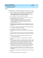
Analog terminals are 6210, 6218, and 6220.
■
To function with the Caller ID feature, TN793B or TN2793B is required with
terminals administered or aliased as CallrID.
Upgrades
Administration
Screen for 6200 Terminals
■
The administration screen shows the Page 1 of the STATION
administration form where, as an example, station 1000 has been
administered as a 6210 terminal.
— This screen shows the default values that will appear when 6210,
6218 or 6220 value is entered as a terminal type.
Issue 1
April 2000
What’s New in DEFINITY ECS
Release 8.2 Job Aid 555-233-754
1
New Switch and Adjunct Support
General Telephony Enhancements - Global
30
Station Form
add station next
STATION
Page 1 of 3
Extension: 1000
Type: 6210
Port:
Name:
Lock Messages? n
Security Code:
Coverage Path 1:
Coverage Path 2:
Hunt-to Station:
STATION OPTIONS
Off Premises Station? n
■
TN:
COR:
COS:
Tests?
1
1
1
y
Message Waiting Indicator: led
Message Lamp Ext: 1000
HELP values for the “Type” field will include 6210, 6218 and 6220.
Caller ID Terminals
■
A Caller ID terminal is required, in addition to the TN793B or TN2793B
circuit pack and Software Release 8 (or later), to implement the Caller ID
feature.
■
Provides an expedient manner for administering non-Lucent Caller ID
terminals when a customer requires the Caller ID feature.
■
New fields on the STATION form:
— Display Caller ID?
— Caller ID Message Waiting Indication?
STATION Form
add station next
Page 1 of 3
STATION
Extension: 1000
Type: CallrID
Port:
Name:
STATION OPTIONS
Off Premises Station? n
Lock Messages? n
Security Code:
Coverage Path 1:
Coverage Path 2:
Hunt-to Station:
TN:
COR:
COS:
Tests?
1
1
1
y
Message Waiting Indicator:
Display Caller ID? y
Caller ID Message Waiting Indication? n
What’s New in DEFINITY ECS
Release 8.2 Job Aid 555-233-754
1
Issue 1
April 2000
New Switch and Adjunct Support
General Telephony Enhancements - Global
■
31
HELP values for the Type field include CallrID.
NOTE:
CallrID is one word, limited to seven characters by Type field
constraints.
■
The fields Display Caller ID? y and Caller ID Message Waiting Indication? n
appear in this form only when CallrID is chosen as the terminal Type.
■
When Display Caller ID field is set to y (yes), calling party information is
transmitted to the Caller ID terminal via Bellcore (US, Bahrain V.23) or NTT
(Japan) protocol.
— When not desired, field should be set to n.
■
Caller ID Message Waiting Indication? n: When set to n (no), FSK
message waiting indication is not transmitted to the Caller ID terminal.
— If FSK message waiting indication is transmitted to a Caller ID
terminal, this field should be set to y.
— Sending FSK message waiting indication to a Caller ID terminal is
independent of the administration of the Message Waiting Indicator
field.
■
The choices for these two fields should be selected according
to the capabilities of the Caller ID terminal used.
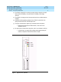
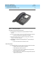
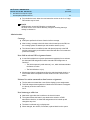
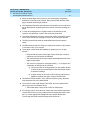
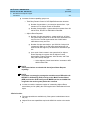
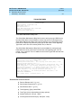
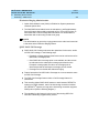
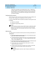
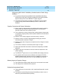
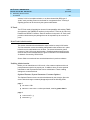
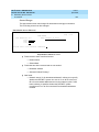
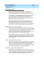
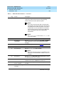
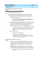
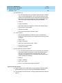
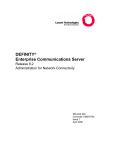
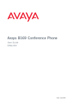
Description of the terminals
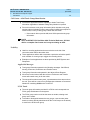
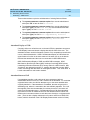
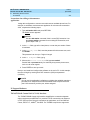
6210
■
6210 is a Lucent set with handset volume control, ringer volume control,
timed switch-hook disconnect, tone dialing (only), Flash, Set Redial, Set
Hold, Data Jack (same T&R pair), and DEFINITY® system LED MWI.
6218
■
6218 is a Lucent set that is the same as the 6220, but without
Speakerphone and without Mute.
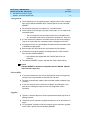
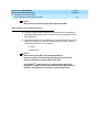
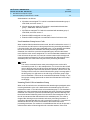
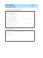
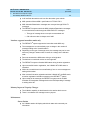
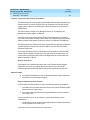
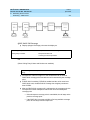
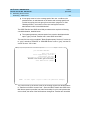
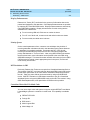
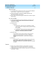
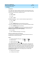
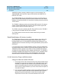
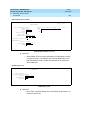
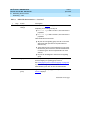
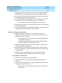
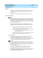
6220
■
6220 is a Lucent set with 6210 features plus Speakerphone, Mute,
Repertory Dialing, Repertory Keylock, Set Personalized Ring, System Hold
CallrID, and Caller ID analog terminals (analog terminals with Caller ID
boxes, or adjuncts) that support Caller ID according to Bellcore, Bellcore
V.23, or NTT standards.
■
MWI is supported via FSK (Bellcore standard). MWI is also optionally
supported via DEFINITY® system LED voltage method or via neon lamp.
■
TeleMatrix and Teledex Caller ID terminals use a neon lamp MWI in
hospitality environments.
What’s New in DEFINITY ECS
Release 8.2 Job Aid 555-233-754
1
Issue 1
April 2000
New Switch and Adjunct Support
General Telephony Enhancements - Global
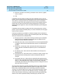
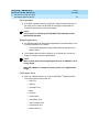
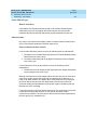
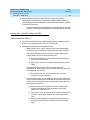
NOTE:
Caller ID feature requires the TN793B or TN2793B circuit pack.
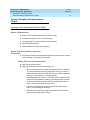
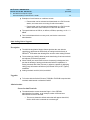
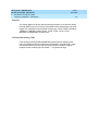
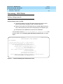
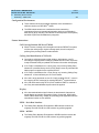
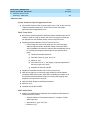
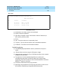
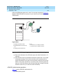
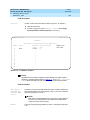
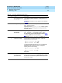
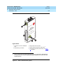
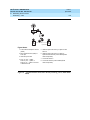
Figure 2.
6210 Analog Telephone
32
What’s New in DEFINITY ECS
Release 8.2 Job Aid 555-233-754
1
Issue 1
April 2000
New Switch and Adjunct Support
General Telephony Enhancements - Global
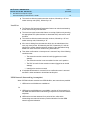
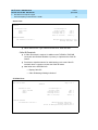
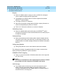
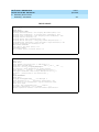
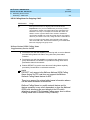
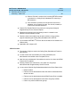
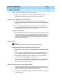
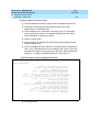
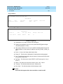
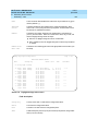
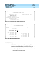
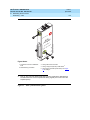
Figure 3.
33
6220 Analog Telephone
Description of the terminals(continued)
■
■
The 6200 family of analog terminals requires DEFINITY® ECS R8
software.
If R8.1 is used as a bugfix, access to the CallrID terminal type is blocked.
— Access is not blocked for the 6200 family of terminals.
■
■
6200 Analog Native Support is available and supported in both Offer
Category A and Offer Category B.
6200 family is compatible with existing DEFINITY® system analog line
circuit packs.
— Can be used where the 8110 terminal is used.
Caller ID terminals
■
TN793B/TN2793B circuit pack supports the following Caller ID terminals:
— TeleMatrix 2802 CID Guest Room Telephone
— Teledex Millennium 2505C and 2510C
— Commercial sets with Caller ID capabilities that comply with the
protocols supported by the Caller ID
— Caller ID display boxes, or adjuncts, that comply with the protocols
supported by the Caller ID
What’s New in DEFINITY ECS
Release 8.2 Job Aid 555-233-754
1
Issue 1
April 2000
New Switch and Adjunct Support
General Telephony Enhancements - Global
34
NOTE:
Many Caller ID protocols specify FSK signaling for MWI.
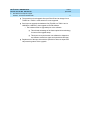
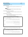
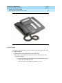
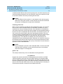
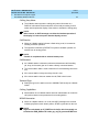
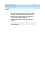
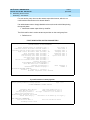
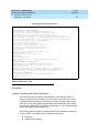
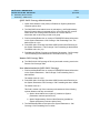
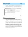
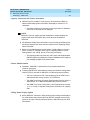
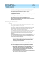
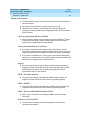
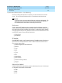
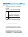
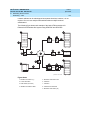
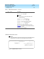
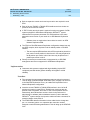
6400 Tip/Ring (Data Module Features)
■
The 6400 Tip/Ring feature supports the operation of an analog adjunct
operating independently on an I2 channel with its own extension for 64xx
DCP telephones.
■
Allows the operation of an analog adjunct to be independent of the digital
telephone’s extension for the use of fax machines or modems without
compromising the user’s voice extension.
— 6416D+
— 6424D+ DCP
NOTE:
When set for I2 operation, the module transmits an
S2-channel button press message for button 01h of group 00h
whenever it detects an analog switch hook flash.
The DEFINITY® system ignores any of these button depression
messages. This does not cause any trouble report. While set for I2
operation, the button press message cannot be suppressed.
What’s New in DEFINITY ECS
Release 8.2 Job Aid 555-233-754
1
New Switch and Adjunct Support
General Telephony Enhancements - Global
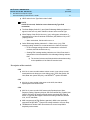
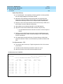
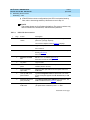
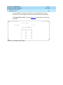
Figure 4.
6416D+ DCP Terminal
Issue 1
April 2000
35
What’s New in DEFINITY ECS
Release 8.2 Job Aid 555-233-754
1
Issue 1
April 2000
New Switch and Adjunct Support
General Telephony Enhancements - Global
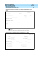
Figure 5.
36
6424D+ DCP Terminal
Administration
The 6416D+ and the 6424D+ terminals are administered with a data option field
for an analog adjunct.
■
Administer as a data module field on add station form.
■
An option on the add station form allows users to administer their own
particular extension.
— Previously, what is now the data option field, was the data module
field for all of the 6400 terminals.
— User can choose from analog, data module, or none.
Issue 1
April 2000
What’s New in DEFINITY ECS
Release 8.2 Job Aid 555-233-754
1
New Switch and Adjunct Support
General Telephony Enhancements - Global
37
Station Form page 1 used for 6416D+ and 6424D+ terminals only
Page1 of X
STATION
Extension: 1003
Type: 6424D+
Port:_______
Name: ________________________
Hunt-to-Station: _______
Lock Messages?
Security Code:
Coverage Path 1:
Coverage Path 2:
n
____
____
____
BCC:
TN:
COR:
COS:
0
1_
1_
1_
STATION OPTIONS
Loss Group:
Data Option: analog
Speakerphone: 2-way
Display Language: english
■
Personalized Ringing Pattern:
Message Lamp Ext:
Mute Button Enabled?
Expansion Module?
MM Complex Data Ext:
1
1000
y
n
n
DEFINITY® system 8.1 provides the following form only if the set is a
6416D+ or 6424D+ and Expansion Module = y on Page 1.
Station form used only with 6416d+ or 6424d+ equipped with XM24 expansion module
Page X of X
STATION
EXPANSION MODULE BUTTON ASSIGNMENT
1: ______________________ 13: ____________________
2: ______________________ 14: ____________________
3: ______________________ 15: ____________________
4: ______________________ 16: ____________________
5: ______________________ 17: ____________________
6: ______________________ 18: ____________________
7: ______________________ 19: ____________________
8: ______________________ 20: ____________________
9: ______________________ 21: ____________________
10: ______________________ 22: ____________________
11: ______________________ 23: ____________________
12: ______________________ 24: ____________________
■
DEFINITY® system 8.1 provides the following form if the set is a 6416D+ or
6424D+ and data option is equal to analog
Issue 1
April 2000
What’s New in DEFINITY ECS
Release 8.2 Job Aid 555-233-754
1
New Switch and Adjunct Support
General Telephony Enhancements - Global
38
Station Form used only with the 6416D+ or the 6424D+ when Data Option equal to
analog
Page 6of 6
STATION
Analog Adjunct
Data Extension: 1003
Name:
COS: 1
COR: 1
TN: 1
ITC: restricted
BCC: 0
ABBREVIATED DIALING
List1:
SPECIAL DIALING OPTION:
ASSIGNED MEMBER (Station with a data extension button for this analog
adjunct)
Ext Name
1:
NOTE:
DSA is impacted when implementing these new features.
Station Form Page 3 Used For All 6400 Voice Terminals Except the 6402/D
Page 3 of X
STATION
SITE DATA
Room:
Jack:
Cable:
Floor:
Building:
______________
____________
___________
______________
______________
ABBREVIATED DIALING
List 1: ________
BUTTON
1:
2:
3:
4:
ASSIGNMENTS
_____________
_____________
_____________
_____________
Headset?
Speaker?
Mounting:
Cord Length:
Set Color:
List 2: ________
5:
6:
7:
8:
n
y
d
0
__________
List 3: ________
_____________
_____________
_____________
_____________
Issue 1
April 2000
What’s New in DEFINITY ECS
Release 8.2 Job Aid 555-233-754
1
New Switch and Adjunct Support
General Telephony Enhancements - Global
39
Station Form Page 3 Used For 6402/D Voice Terminals Only
Page 3 of X
STATION
SITE DATA
Room:
Jack:
Cable:
Floor:
Building:
______________
____________
___________
______________
______________
ABBREVIATED DIALING
List 1: ________
Headset?
Speaker?
Mounting:
Cord Length:
Set Color:
List 2: ________
n
y
d
0
__________
List 3: ________
BUTTON ASSIGNMENTS
1: call-appr________
2: call-appr________
Station Form Page 4 Used For 6402/D Voice Terminals Only
Page 4 of X
STATION
FEATURE BUTTON ASSIGNMENTS
1: _____________________
2: _____________________
3: _____________________
4: _____________________
5: _____________________
6: _____________________
7: _____________________
8: _____________________
9: _____________________
*: _____________________
0: _____________________
#: _____________________
Issue 1
April 2000
What’s New in DEFINITY ECS
Release 8.2 Job Aid 555-233-754
1
New Switch and Adjunct Support
General Telephony Enhancements - Global
40
Station Form Page 4 Used For 6416D+ Only
Page 4 of X
STATION
FEATURE BUTTON ASSIGNMENTS
1: _____________________
2: _____________________
3: _____________________
4: _____________________
5: _____________________
6: _____________________
7: _____________________
8: _____________________
Station Form Page 4 Used For 6424D+ Only
Page 4 of X
STATION
FEATURE BUTTON ASSIGNMENTS
1: ______________________ 9:
2: ______________________ 10:
3: ______________________ 11:
4: ______________________ 12:
5: ______________________ 13:
6: ______________________ 14:
7: ______________________ 15:
8: ______________________ 16:
____________________
____________________
____________________
____________________
____________________
____________________
____________________
____________________
Issue 1
April 2000
What’s New in DEFINITY ECS
Release 8.2 Job Aid 555-233-754
1
New Switch and Adjunct Support
General Telephony Enhancements - Global
41
Station Form Page 5 Used for all 6400 Display Sets Other Than the 6402D
Page 5 of X
STATION
SOFTKEY BUTTON ASSIGNMENTS
1: ______________________
2: ______________________
3: ______________________
4: ______________________
5: ______________________
6: ______________________
7: ______________________
8: ______________________
9: ______________________
10: ______________________
11: ______________________
12: ______________________
Station Form used Only With 6416D+ or 6424D+ Equipped With XM24 Expansion
Module
Page X of X
STATION
EXPANSION MODULE BUTTON ASSIGNMENT
1: ______________________ 13: ____________________
2: ______________________ 14: ____________________
3: ______________________ 15: ____________________
4: ______________________ 16: ____________________
5: ______________________ 17: ____________________
6: ______________________ 18: ____________________
7: ______________________ 19: ____________________
8: ______________________ 20: ____________________
9: ______________________ 21: ____________________
10: ______________________ 22: ____________________
11: ______________________ 23: ____________________
12: ______________________ 24: ____________________
Issue 1
April 2000
What’s New in DEFINITY ECS
Release 8.2 Job Aid 555-233-754
1
New Switch and Adjunct Support
General Telephony Enhancements - Global
42
6400 Terminal Parameters Form
Page X of X
STATION
6400-TYPE TERMINAL PARAMETERS
Default Parameter Set: 1
Customize Parameters? y
OPTIONS
Display Mode:
Volume:
PRIMARY LEVELS
Voice Transmit (dB):
Voice Receive (dB):
Touch Tone Transmit (dB):
Handset Expander Enabled?
Voice Sidetone (dB):
Touch Tone SideTone (dB):
2-WAY BUILT-IN SPEAKER LEVELS:
Voice Transmit (dB):
Touch Tone Transmit (dB):
1-WAY BUILT-IN SPEAKER LEVELS
Voice Receive (dB):
Voice Receive (dB):
Touch Tone SideTone (dB):
Tip Fields
Fields, field placements, and valid keywords
6400
8400/ 9400
Differences
6402/D
8403B
6402 has 1 less call appearance.
6408
8410B
6408 has 2 less call appearances and no 2 wayspeaker-phone.
6408+
8405B
6408+ has 3 more call appearances
6408D
8405D
6408D has 3 more call appearances and no 2way speaker-phone.
6408D+
8405D+
6408D+ has 3 more call appearances.
6416D+
8434D
6416D+ has 18 less call appearances and 3 less
soft-keys
(12 v 15). The 8434 has a 2 x 40 display instead
of a 2 x 24 display
6424D+
8434D
6416D+ has 18 less call appearances and 3 less
soft-keys
(12 v 15). The 8434 has a 2 x 40 display instead
of a 2 X 24 display
What’s New in DEFINITY ECS
Release 8.2 Job Aid 555-233-754
1
Issue 1
April 2000
New Switch and Adjunct Support
General Telephony Enhancements - Global
43
Support for 24-button expansion modules
The XM24 expansion module is fully functional when administered together
with the 6416D+ and 6424D+ voice terminals.
■
Abort Transfer
■
The Abort Transfer provides the user with the optional capability to abort a
transfer attempt when pressing a non-idle line appearance or going onhook, putting the previously soft-held call on hard hold.
■
In a Pre Release 8.1 operation, the user might have received an urgent call
that they needed to pick up and then later transfer the urgent call to yet
another party.
— The user forgets that the first call is still on soft-hold awaiting
transfer and the user instead presses the transfer button to transfer
the urgent call to a third party.
— As soon as the user presses the transfer button, the first and second
calls are transferred together which is not what the user intended.
— If the user of a DCP, Hybrid, Wireless, or ISDN-BRI terminal presses
a non-idle call appearance (or goes on-hook) in the middle of
performing a Transfer operation, the Transfer operation is not
aborted but is left in an active state.
■
Abort Transfer allows abort the transfer operation whenever he/she
presses a non-idle call appearance in the middle of the transfer operation
or when the user hangs-up (assuming that the Transfer Upon Hang-Up
feature is not enabled).
■
The original call that was on soft-hold in the transfer-pending mode will be
changed to be on hard-hold so that the original call is not lost.
■
When the user then presses the transfer button, the user will be initiating a
new transfer for the call appearance he/she is currently on.
Abort Conference
■
The Abort Conference enhancement provides the user with the optional
capability to abort a conference attempt when going on-hook, putting the
previously soft-held call on hard hold.
■
This allows the user of a DCP, Hybrid, Wireless, or ISDN-BRI terminal to
abort the conference operation whenever they hang-up.
NOTE:
The original call that was on soft-hold in the conference-pending mode
will be changed to be on hard-hold so that the original call is not lost.
■
When the user later presses the conference button, the user will be
initiating a new conference for the call appearance they are currently on.
Issue 1
April 2000
What’s New in DEFINITY ECS
Release 8.2 Job Aid 555-233-754
1
New Switch and Adjunct Support
General Telephony Enhancements - Global
44
NOTE:
The Abort Transfer / Abort Conference features are not applicable to
Attendant Consoles.
Administration
Enable Abort Transfer Operation and Enable Abort Conference
Operation
■
Enabled/disabled on a per-system basis by the use of 2 new fields on the
system-parameters features form.
■
Automatically disabled on upgrades.
New on the system-parameters features form
■
“Abort Transfer?” and “Abort Conference Upon Hang-Up?” are added to
Page 5 of the form as shown
change system-parameters features
FEATURE-RELATED SYSTEM PARAMETERS
Page 5 of 10
Public Network Trunks on Conference Call: 5
Auto Start? n
Conference Parties with Public Network Trunks: 6
Auto Hold? n
Conference Parties without Public Network Trunks: 6
Attendant Tone? y
Night Service Disconnect Timer (seconds): 180
Bridging Tone? n
Short Interdigit Timer (seconds): 3
Conference Tone? n
Unanswered DID Call Timer (seconds): ____
Intrusion Tone? n
Line Intercept Tone Timer (seconds): 30
Special Dial Tone? n
Long Hold Recall Timer (seconds): 160
Reset Shift Timer (seconds): 0
Station Call Transfer Recall Timer (seconds): 0
DID Busy Treatment: tone
Allow AAR/ARS Access from DID/DIOD? _
Allow ANI Restriction on AAR/ARS? _ Transfer Upon Hang-Up? n
Abort Conference Upon Hang-Up? n
Abort Transfer? n
7405ND Numeric Terminal Display? n
7434ND? n
DISTINCTIVE AUDIBLE ALERTING
Internal: 1
External: 2
Priority: 3
Attendant originated Calls:_ ________
DTMF Tone Feedback Signal to VRU - Connection: _
Disconnection: _
■
Abort Transfer? Fixed field identifying whether the Abort Transfer feature is
enabled or disabled.
— Help: n(o), y(es)
— Default: n
— Error: invalid entry, press help.
■
Abort Conference Upon Hang-Up? Fixed field identifying whether the Abort
Conference feature is enabled or disabled.
— Help: n(o), y(es)
What’s New in DEFINITY ECS
Release 8.2 Job Aid 555-233-754
1
Issue 1
April 2000
New Switch and Adjunct Support
General Telephony Enhancements - Global
45
— Default: n
— Error: invalid entry, press help.
Attendant Vectoring
Attendant Call Vectoring is a stand alone feature that is supported on a single
switch environment with or without CAS. Attendant Call Vectoring permits unique
treatment for each of the attendant-seeking calls according to a number of factors,
as defined by the Vector Directory Numbers for each functionality, so as to provide
a highly flexible approach for managing incoming calls to an attendant on a
DEFINITY switch.
Terminology and Acronyms
Table 2.
Terms and Acronyms
Term
Meaning
BSR
Best Service Routing
CAS
Centralized Attendant Service
IAS
Inter-PBX Attendant Service
RLT
Release Link Trunk
TAAS
Trunk Answer Any Station
TN
Tenant Number. Tenant numbers are assigned to all endpoints in the system
and indicates which tenant partition the endpoint belongs to. If tenant
partitioning is not administered the system has only one “universal” tenant
partition and all endpoint TN numbers are defaulted to 1.
VDN
Vector Directory Number
What’s New in DEFINITY ECS
Release 8.2 Job Aid 555-233-754
1
Issue 1
April 2000
New Switch and Adjunct Support
General Telephony Enhancements - Global
46
Attendant Group Calls
Attendant group calls are calls directed to an attendant group; calls to an
individual attendant (via the assigned extension) are not considered attendant
group calls. Calls begin as or become attendant group under the following
conditions:1
■
Call to Listed Directory Number (LDN)
■
Attendant group in coverage path
■
Attendant control of trunk group access
■
Attendant return calls
■
Attendant serial calls
■
Calls forwarded to attendant group
■
Controlled Restriction
■
Dialed attendant access code
■
Emergency access (dialed FAC or off hook timeout)
■
VIP Wakeup
■
DID/Tie/ISDN intercept treatment
■
DID time-out due to Unanswered DID Call Timer expiry
■
DID busy treatment
■
Call Park time-out
■
Call Transfer time-out
■
Security Violation Notification (SVN)
■
Multifrequency signaling with attendant group as terminating destination
■
CDR buffer full with attendant group as Call Record Handling Option
■
Trunk incoming destination is attendant group
■
Trunk group night service destination is attendant group
■
Hunt group night service destination is attendant group
■
Automatic Circuit Assurance (ACA) referral calls
■
VDN routes to the attendant access code
Attendant group calls terminate to the attendant group associated with a particular
party’s tenant number (TN). When tenant partitioning is not administered, the
system can have only one “universal” tenant partition and attendant group in
which attendants can be members. Any attempt to assign an attendant to an
1.
Multimedia data calls can also be sent to an attendant group, but only voice is being
supported for R8 attendant vectoring. Data calls were not originally supported for basic
vectoring and support is still incomplete. Since there is no need to provide this
functionality, MMCH calls will be blocked from attendant vectoring.
What’s New in DEFINITY ECS
Release 8.2 Job Aid 555-233-754
1
Issue 1
April 2000
New Switch and Adjunct Support
General Telephony Enhancements - Global
47
attendant group other than 1 is denied. All endpoints in the system are defaulted
to TN 1 which by default belongs to attendant group 1. Any attempt to assign TN
numbers other than 1 is also denied. So, attendant group calls will always
terminate to attendant group 1. For example, station 2000 is assigned TN 1 so
when the attendant access code is dialed from station 2000, the call terminates to
attendant group 1.
When tenant partitioning is administered, attendants can be assigned to multiple
attendant groups and endpoints can be assigned TN numbers for any of the
tenant partitions. The TN is associated with an attendant group via the tenant
form. So, tenant partitions 1 and 2 can be associated with separate attendant
groups or the same attendant group. Attendant group calls still terminate to the
attendant group assigned to a party’s TN. For example, station 2000 is assigned
TN 1 which is associated with attendant group 1. Station 3000 is assigned TN 2
which is associated with attendant group 2. When the attendant access code is
dialed from station 2000, the call terminates to attendant group 1 and when dialed
from station 3000, terminates to attendant group 2. This is a flexible method of
assigning multiple tenant partitions to be controlled by one attendant group or
assigning each tenant partition a separate attendant group.
Call Vectoring
Call vectoring provides a highly flexible approach to managing calls. It consists of
three basic components:
1. A Vector Directory Number (VDN)
2. Vectors
3. Vector commands
The VDN is an extension which can be directly dialed or administered as a
destination (e.g., last point in a coverage path, night service destination, etc.).
Each VDN is assigned a vector in which call handling procedures are
programmed using vector commands. Once the call goes to a vector, the call’s
routing and treatment are determined by the commands in the vector.
Attendant Vectoring
A new customer option for attendant vectoring will be added and will not be
available if RLT CAS is turned on. So, this feature will be available in nondistributed attendant environments and distributed attendant environments for IAS
and QSIG CAS. When the new option is on, attendant vectoring will be available
for customers to program how they want their attendant group calls processed.
This feature will be based upon and use existing call vectoring and attendant
administration.
Just as TN assignment currently determines which attendant group calls are
terminated to, the TN assignment will also determine which VDN the calls are
redirected to (i.e., a VDN field will be added for each tenant partition). If a VDN is
administered, attendant group calls will be redirected to the VDN rather than the
attendant group. If a VDN is not assigned calls will terminated to the associated
What’s New in DEFINITY ECS
Release 8.2 Job Aid 555-233-754
1
Issue 1
April 2000
New Switch and Adjunct Support
General Telephony Enhancements - Global
48
attendant group as they currently do. How Definity determines which party’s TN to
use in call scenarios will remain unchanged by attendant vectoring. The VDN for
the selected TN will apply. For example, the selected TN for calls covered to an
attendant group, is the called user’s, not the calling user’s, TN. When tenant
partitioning is not administered, the system can have only one partition and
attendant group. All attendant group calls are directed to attendant group 1. The
form to administer TN associations is not accessible so system-wide console
assignments apply. To follow the existing principals of this administration, the
attendant vectoring VDN assignment will appear on the Console Parameters form
when partitioning is turned off. When it is turned on, the field will be removed from
the console form and the contents will be automatically copied to TN 1.
To associate VDNs and vectors for attendant vectoring, a new field will be added
to both the VDN and the call vectoring forms to indicate attendant vectoring.
When attendant vectoring is indicated for VDNs and vectors, all call center
associated fields will be removed (Skills, BSR, etc.). There will be no restrictions
applied to attendant and non-attendant vectoring. For example, an attendant VDN
can point to a non-attendant vector and vice versa. The same is true for vector
commands. For example, an attendant VDN which points to an attendant vector
can have a vector step which routes to another VDN which is a non-attendant
VDN. In this case, the call will be removed from queue and treated as though it
had just entering vector processing rather than a continuation from one VDN to
another. The reverse will also be true if non-attendant VDNs get subsequently
routed to attendant VDNs. The following commands will be provided for attendant
vectoring:
1.
■
Announcement <extension>
■
busy
■
disconnect after announcement <extension>
■
goto step <step #> if time-of-day is <day> <hour>:<minute> to <day>
<hour>:<minute>
■
goto step <step #> if <unconditionally, queue-fail>
■
goto vector <vector #> if time-of-day is <day> <hour>:<minute> to <day>
<hour>:<minute>
■
goto vector <vector #> if <unconditionally, queue-fail>
■
queue-to attd-group
■
queue-to attendant <extension>
■
queue-to hunt-group <group number> pri <priority level>
■
route-to number <number> with cov <y|n> if <unconditionally>1
■
wait-time <seconds> secs hearing <silence, ringback, music>
In this case, unconditional is not a choice, it is the only option
What’s New in DEFINITY ECS
Release 8.2 Job Aid 555-233-754
1
Issue 1
April 2000
New Switch and Adjunct Support
General Telephony Enhancements - Global
■
wait-time <seconds> secs hearing <extension> then <silence, ringback,
music, continue>
■
stop
49
If attendant vectoring results in putting a call in the attendant queue, it will be
placed in queue with the priority as administered on the console parameter form.
There will be no changes made to the attendant priority queue for attendant
vectoring. Note that even when partitioning is turned on and multiple attendant
groups exist, all queues have the same priority assignments. Priority queue
administration also applies for calls to an individual attendant (via the assigned
extension).
If attendant vectoring results in putting a call in the hunt group queue, it will be
placed in queue with the indicated priority. To use this command, the hunt group
must be vector controlled.
Until some mechanism is provided for customers to apply vector commands or
specialized administration to specific types of attendant group calls, the following
will not be redirected to the attendant VDN:
■
Emergency Access - these calls will still be sent directly to the attendant
group. However, an attendant vectoring VDN can be assigned as the
emergency access redirection extension.
■
Attendant return calls - these calls will still be sent to the original attendant
if available or placed into the attendant group queue if no attendants are
available.
■
Serial calls - as with return calls, serial calls will still be returned to the
original attendant if available and placed in queue if no attendants are
available.
■
VIP Wakeup calls - these reminder calls will still be sent directly to the
attendant group.
■
Call Park time-out - these calls result in a conference (caller, principal, and
attendant) and call vectoring does not allow conferenced calls to be
vectored.
■
Call Transfer time-out - these calls are controlled by the attendant return
call timer and are processed as though they had been attendant extended
calls (i.e., actual attendant return calls). It is unclear when or why this
functionality was introduced, but the design will not be changed in order to
allow the calls to be vectored.
One of the main reasons for providing attendant vectoring is to allow attendant
group calls to be routed anywhere when the system is in night service. For R8,
there will be no additional night service functionality provided for attendant
vectoring. The desired night service routing can be provided using the existing
night station service in conjunction with attendant vectoring. All existing night
service rules will remain in place (e.g., night console service supersedes night
station service which supersedes TAAS). Attendant group calls will not be
What’s New in DEFINITY ECS
Release 8.2 Job Aid 555-233-754
1
Issue 1
April 2000
New Switch and Adjunct Support
General Telephony Enhancements - Global
50
redirected to attendant vectoring when the system is in night service unless a
night console is available. Otherwise, they will continue to be redirected to the
applicable night service processing. In order to achieve attendant vectoring for
calls when the system is in night service without a night console, the night station
service extensions must be attendant vectoring VDN extensions.
Attendant VDN
The fact that VDN extensions can be dialed directly or calls can be transferred to
VDN extensions will remain unchanged for attendant VDNs.
Currently, VDN extensions can be assigned to:
■
Hunt Group night destination - An attendant vectoring VDN can be
assigned as a hunt group’s night destination. Calls to that hunt group when
it is in night service will be redirected to the VDN and attendant vectoring
will apply. Note that hunt group night service does not apply if the hunt
group is vector controlled. When vector? is y, the night service destination
field is removed from the form. In order for a hunt group to be available in
vectoring for the queue-to hunt-group command, the hunt group must be
vector controlled. So, the hunt group in the route-to command could be in
night service and the call would then terminate to the indicated night
service destination.
■
LDN and trunk night destination - One or all trunk groups can be placed
into night service and an attendant vectoring VDN can be assigned as the
group’s night service destination. If a night destination is assigned for LDN
calls, it will over-ride (for LDN calls) the trunk group’s night destination.
Either of these destinations can be an attendant vectoring VDN. However, if
tenant partitioning is administered and the trunk group night service
destination is the attendant group, the call will be redirected to the VDN
associated with the trunk group’s TN. If, instead, the night service
destination is explicitly assigned to a particular attendant vectoring VDN, it
may or may not be the VDN that would have resulted had the night
destination been the attendant group.
■
Tenant night destination - For tenant partitioning, each partition can be
assigned a night destination. When tenant partitioning is turned off, local
attendant group calls are sent to the LDN night destination. When
partitioning is turned on, local attendant seeking calls are sent to the
partition’s night destination.
■
Trunk group incoming destination - The incoming destination can be an
attendant vectoring VDN except for RLT trunk groups. As in trunk group
night service, an assigned incoming destination to an attendant vector
could result in the call being sent to a different VDN than if the destination
had been assigned to the attendant group.
■
Last coverage point in a coverage path - Attendant VDNs can be assigned
as a coverage point.
■
Abbreviated dialing lists - Attendant VDNs can be assigned to abbreviated
dialing lists.
Issue 1
April 2000
What’s New in DEFINITY ECS
Release 8.2 Job Aid 555-233-754
1
New Switch and Adjunct Support
General Telephony Enhancements - Global
51
■
Emergency access redirection - An attendant VDN can be assigned to
emergency access redirection. When the attendant’s emergency queue
over-flows or when the attendant group is in night service, all emergency
calls will be redirected to this VDN. Careful thought should be given to
routing these calls off-switch.
■
QSIG CAS number for attendant group calls - An attendant VDN can be
assigned to this number which determines where attendant group calls at a
QSIG Branch are processed. This will allow local vectoring at a Branch
prior to routing the calls to the Main or elsewhere.
■
Auxiliary data for the following button assignments - In keeping with
existing procedures, attendant VDNs will not be denied as auxiliary button
data for:
■
Facility busy indication - visual indication of busy or idle status for
the associated extension
■
Manual message waiting indication - light a message waiting lamp
on the station associated with the button
■
Manual signaling - rings the station associated with the button
■
Remote message waiting indicator - message waiting status lamp
automatically lights when a LWC message has been stored in the
system for the associated extension
Attendant Routing Examples
The following examples outline how the Attendant Vectoring commands can be
used to route calls in an attendant environment. For these examples, consider the
following vectors and vector administration.
Assume the following attendant vectors (tenant partitioning is turned on):
Table 3.
Attendant Vectoring Vectors
VDN 1999
vector 1
VDN 2999
vector 2
1. goto step 6 if time-of-day is
all 12:00 to 13:00
2. queue-to attd-group
3. goto step 7 if queue-fail
4. wait 999 secs hearing music
5. busy
6. route-to number 4000 with
cov y if unconditionally
7. route-to number
93035381000 with cov y if
unconditionally
1. queue-to attd-group
2. goto step 6 if queue-fail
3. announcement 9000
4. wait 999 seconds hearing music
5. disconnect after announcement
9001
6. queue-to hunt-group 1
7. goto step10 if queue-fail
8.wait 999 secs hearing ringback
9. busy
10. route-to number 93035381000
with cov y if unconditionally
VDN 3999
vector 3
1. goto step 7 if time-of-day is all
12:00 to 13:00
2. queue-to attd-group
3. goto step 7 if queue-fail
4. announcement 9000
5. wait 15 seconds hearing music
6. goto step 4 if unconditionally
7. queue-to attendant 6000
8. goto step 10 if queue-fail
9. wait 999 secs hearing ringback
10. route-to number 93035381000
with cov y if unconditionally
What’s New in DEFINITY ECS
Release 8.2 Job Aid 555-233-754
1
Issue 1
April 2000
New Switch and Adjunct Support
General Telephony Enhancements - Global
52
Administration is as follows:
a. All stations are assigned TN 1 which is associated with attendant group 1,
VDN 1999, and music source 1
b. All trunk groups are assigned TN 2 which is associated with attendant
group 1, VDN 2999, and music source 2
c. All VDNs are assigned TN 3 which is associated with attendant group 2,
VDN 3999, and music source 3
d. Extension 4000 is assigned to a hunt group 1
e. Extension 6000 is assigned to an attendant console for direct access
Local Attendant Group Access Code
When a station dials the attendant access code, the call is redirected to vector 1. If
it is lunch time, the call is sent to a hunt group and vector processing terminates. If
it is not lunch time, the call is sent to attendant group 1. If an attendant is available,
the call is terminated to the attendant and vector processing terminates.
Otherwise, the call will be queued to the attendant group and the caller hears
music from the music source assigned to TN 1 until an attendant answers the call.
If the call cannot be queued, it is routed to a remote location with coverage and
vector processing terminates. If the call is unanswered after 999 seconds in the
attendant queue, the caller hears busy and vector processing terminates.
NOTE:
The route-to command leaves vector processing as soon as the call is
successfully routed. So, in the example above, if it is lunch time the call will
route to the hunt group and all hunt group processing will then apply. If the
group is assigned a queue and the call can be queued, it will be. If not, and
coverage criteria is met, the call will follow the hunt group’s coverage path. If
the hunt group is in night service, the call will go to the hunt group’s night
service destination. If the route-to command had indicated coverage “n”, the
hunt groups coverage path would not have been followed and vector step 7
would apply.
Incoming Trunk Calls to Attendant Group
When a call is received on a trunk which has the attendant group assigned as the
incoming destination or the call is addressed to the attendant group, the call is
redirected to vector 2. The call is then sent to attendant group 1. If an attendant is
available, the call is terminated to the attendant and vector processing terminates.
Otherwise, the call will be queued to the attendant group and the caller will hear
the announcement followed by music from the music source assigned to TN 2. If
the call is unanswered after 999 seconds in the attendant queue, the caller is
dropped after hearing an announcement and vector processing terminates. If
queueing to the attendant fails, the call is queued to hunt group 1. If a member is
available to take the call, it will be terminated to the member and vector
processing terminates. If a member is not available and the call can be queued, it
will be and the caller will hear ringback until a member answers. If the call is
Issue 1
April 2000
What’s New in DEFINITY ECS
Release 8.2 Job Aid 555-233-754
1
New Switch and Adjunct Support
General Telephony Enhancements - Global
53
unanswered after 999 seconds in the hunt group queue, the caller hears busy and
vector processing terminates. If the call cannot be queued, the call will be routed
to the remote location and vector processing will terminate.
NOTE:
The main difference from scenario 1 is queueing the call to the hunt group
rather than routing the call there. In this scenario, the call will not follow the
hunt group’s coverage path or night service destination.
Incoming LDN Calls
When a call is received for an LDN, the call is redirected to vector 3. If it is lunch
time, the call is sent to attendant 6000. If the attendant is available, the call is
answered and vector processing terminates. If the attendant is not available the
call is placed into queue and the caller hears ringback until the attendant answers
the call. If the call is unanswered after 999 seconds in the attendant’s queue, the
call is sent to the remote location and vector processing terminates. If the call
cannot be placed in attendant 6000’s queue, the call is routed to a remote location
and vector processing terminates. If it is not lunch time, the call is sent to
attendant group 2. If an attendant is available, the call is terminated to the
attendant and vector processing terminates. Otherwise, the call will be queued to
the attendant group and the caller will hear an announcement followed by music
(from the music source assigned to TN 3) every 15 seconds. If the call cannot be
queued, it is sent to attendant 6000.
NOTE:
Vector 3 attempts to queue the call to attendant 6000. A route-to command
could have been used also, but care should be taken since an attendant
cannot be assigned a coverage path.
QSIG CAS
This example shows how you can use Attendant Vectoring with CAS.
CAS BRANCH
Suppose the customer would like to always play an announcement at a QSIG
CAS branch before routing the call to the QSIG CAS main. An attendant VDN
(assume 1000) would need to be administered in the QSIG CAS Number field at
the branch instead of the number to the QSIG CAS main’s attendant access code
(assume 303-538-0 with AAR access code 9). The following vector would play an
announcement and then route the call to the QSIG CAS main.
Issue 1
April 2000
What’s New in DEFINITY ECS
Release 8.2 Job Aid 555-233-754
1
New Switch and Adjunct Support
General Telephony Enhancements - Global
Table 4.
54
QSIG CAS Vector
VDN 1000
vector 1
1. announcement 9000
2. route-to number 93035380 with
cov y if unconditionally
CAS MAIN
Calls from a QSIG branch are sent to the main with the main’s attendant access
code as the destination address so these calls are automatically attendant group
calls. The VDN to which these calls get redirected will depend on the TN of the
incoming trunk.
Night Station Service
This example shows how you can make use of the Attendant Vectoring features
for night service.
Administration is as follows:
Table 5.
Night Station Service Vectors
VDN 4999
vector 4
VDN 5999
vector 5
1. route-to number 93035381000 with cov y if
unconditionally
1. route to number 6000 with cov n if unconditionally
2. route-to number 93035381000 with cov y if
unconditionally
a. Trunk group 1 is assigned TN 2 which is associated with attendant group 1,
and night destination 4999
b. Trunk group 2 is assigned TN 1 which is associated with attendant group 2,
and night destination 5999
c. Extension 6000 is assigned to a station
d. System night service is on
When a non-DID call comes in on trunk group 1, the call is redirected to VDN
4999 which routes it to a remote location.
When a non-DID call comes in on trunk group 2, the call is redirected to VDN
5999 which routes it to station 6000. If station 6000 is unavailable, the call will not
What’s New in DEFINITY ECS
Release 8.2 Job Aid 555-233-754
1
Issue 1
April 2000
New Switch and Adjunct Support
General Telephony Enhancements - Global
55
cover on station 6000’s coverage path. Vector processing will continue and route
the call to a remote location.
NOTE:
When station night service is active, calls are processed according to the
administered night destination for the trunk group, not the night destination
for the associated TN (i.e., these are not attendant group calls). If the night
destination had been assigned as attd or left unassigned, the calls would
have become attendant group calls and would be processed according to
the partitions night destination.
Trouble Isolation: List Trace Command
Two new options for the list trace command allow customers and Tier 1
technicians to troubleshoot misdirected calls, trunking/routing problems, and call
denials.
■
list trace station nnnnn (where nnnnn is the number of the station you
want to troubleshoot)
■
list trace tac xxxx (where xxxx is the identifier of the trunk you want to
troubleshoot)
Execute the list trace command with the relevant option word.
■
To see all the list trace options, execute list trace at the command line.
■
To redisplay the most-recently done trace, execute list trace previous at
the command line.
■
To cancel a trace in progress, press F7 .
!
WARNING:
DEFINITY release 8.2 does not record all denial events. Always
check translations before you escalate a problem.
For example, COR to COR restrictions are not recorded in the event
log. If the event log does not have entries for the calling/called
parties, check the COR translations.
Diagnostic Procedure
1. Execute list trace station nnnnn or list trace tac xxxx from the command
line.
For tone traces (denial events) convert the call ID (cid) from decimal to
hexidecimal, and continue with the following steps.
Issue 1
April 2000
What’s New in DEFINITY ECS
Release 8.2 Job Aid 555-233-754
1
New Switch and Adjunct Support
General Telephony Enhancements - Global
56
2. Execute the display events command from the command line. Search for
CATEGORYCATEGORY denial.
3. Search the EVENTS REPORT for the hexidecimal cid to troubleshoot the
problem.
Diagnostic Example: list trace to Diagnose
Intercept Tone (Denial)
In this example, the customer heard an intercept tone (denial of service).
Execute list trace station nnnnn and make the test call from that station:
list trace station 51001
LIST TRACE
time
data
11:58:57
active station
51001 cid 528
11:59:02
dial 9538
11:59:02
denial station
51001 cid 528
11:59:02 TRACE COMPLETE station 51001 cid 528
Convert 528 to hexidecimal (0x210) and execute display events CATEGORY
denial.
Search for event data 2 for hexidecimal cid 210:
EVENTS REPORT
Event Event
Type Description
Event Event First
Data 1 Data 2 Occur
1343 Need higher FRL to route 6
210
Last
Occur
Evnt
Cnt
02/11/11:59 02/11/11:59 1
Issue 1
April 2000
What’s New in DEFINITY ECS
Release 8.2 Job Aid 555-233-754
1
New Switch and Adjunct Support
General Telephony Enhancements - Global
57
Diagnostic Example: list trace to Diagnose Fast
Busy (Reorder Tone)
In this example, no trunks were available in trunk group 1.
Execute list trace station nnnnn and make the test call from that station:
list trace station 51001
LIST TRACE
time
data
12:04:30
active station
51001 cid 531
12:04:32
dial 56001
12:04:32
reorder trunk-group 1
cid 531
12:04:032 TRACE COMPLETE station 51001 cid 531
Convert 531 to hexidecimal (0x213) and execute display events CATEGORY
denial.
Search for event data 2 for hexidecimal cid 213:
EVENTS REPORT
Event Event
Type Description
Event Event First
Data 1 Data 2 Occur
1012 Destination Unavailable
6
213
Last
Occur
Evnt
Cnt
02/11/12:04 02/11/12:04 1
Issue 1
April 2000
What’s New in DEFINITY ECS
Release 8.2 Job Aid 555-233-754
1
New Switch and Adjunct Support
General Telephony Enhancements - Global
58
Diagnostic Example: list trace to Diagnose DID
not Ringing Correctly
In this example, the trace verifies the inbound digits from the network and traces
DID trunk to VDN 52099, to vector 1, terminated to agent 51001.
Execute list trace tac xxxx and place the test call from the network:
list trace tac 7
LIST TRACE
time
data
11:38:30
active trunk-group 79 member 1 cid 516
11:38:33
dial 52099
11:38:33
ring vector 1
cid 516
11:38:41
active station
51001 cid 516
11:38:41 TRACE COMPLETE station 51001 cid 516
Diagnostic Example: list trace to Diagnose
Outpulsing Error
In this example, the trace verifies the outpulsing of incorrect digits to the central
office (area code 303 is required). Trunk-group 81 member 1 outpulsed 5381788.
The network rejected the call because it required a 10-digit number. The call did
not complete, and the caller went on-hook.
Execute list trace station nnnnn and place the test call from the station:
list trace station 51001
LIST TRACE
time
data
11:17:17
active station
51001 cid 522
11:17:20
dial 9538
11:17:20
term trunk-group 81
cid 522
11:17:21
dial 953817
11:17:21
seize trunk-group 81 member 1 cid 522
11:17:24
dial 95381788
11:17:24
outpulse done 5381788
11:17:32
active trunk-group 81 member 1 cid 522
11:17:34
idle station
51001 cid 522
11:17:34 TRACE COMPLETE station 51001 cid 522
Issue 1
April 2000
What’s New in DEFINITY ECS
Release 8.2 Job Aid 555-233-754
1
New Switch and Adjunct Support
General Telephony Enhancements - Global
59
Diagnostic Example: list trace to Diagnose
Station not Ringing
In this example, the trace verifies the inbound DID call to x52001 is forwarded offnet and the trunk hung up.
Execute list trace station nnnnn:
list trace tac 7
LIST TRACE
time
data
10:42:15
active trunk-group 79 member 1 cid 504
10:42:18
term station 52001 cid 504
10:42:18
call-forwarding 9538
10:42:18
term trunk-group 81
cid 504
10:42:18
call-forwarding 95381788
10:42:18
seize trunk-group 81 member 1 cid 504
10:42:21
call-forwarding 95381788
10:42:21
outpulse done 3035381788
10:42:30
idle trunk-group 81 member 1 cid 504
10:42:30 TRACE COMPLETE trunk-group 79 cid 504
Diagnostic Example: list trace to Analyze Call
Coverage
In this example, the trace verifies the inbound DID call to x52002, no answer; rings
x51002, no answer; 2010 no answer, 2010 (final point of coverage) continues to
ring and then answers.
Execute list trace station nnnnn:
list trace tac 7
LIST TRACE
time
data
10:21:03
active trunk-group 79 member 1 cid
10:21:06
dial 52002
10:21:06
ring station 52002 cid 512
10:21:16
no answer station 52002 cid 512
10:21:16
coverage station 51002 cid 512
10:21:32
no answer station 51002 cid 512
10:21:32
coverage station 2010 cid 512
10:21:47
no answer station 2010 cid 512
10:21:47
coverage
cid 512
10:21:55
active station
2010 cid 512
10:21:57
idle station cid 512
10:21:57 TRACE COMPLETE trunk-group 79 cid 512
512
What’s New in DEFINITY ECS
Release 8.2 Job Aid 555-233-754
1
Issue 1
April 2000
New Switch and Adjunct Support
General Telephony Enhancements - Global
60
Diagnostic Example: list trace to Analyze Trunk
Signaling Failure
In this example, the trunk wink was not received from the network.
Notice there is no trunk seizure message and digits are not outpulsed. Check the
hardware error log for trunk group 2 errors indicating seizure failure.
list trace station 51001
time
data
10:35:13
active station
51001 cid 1347
10:35:18
dial 9255
10:35:18
term trunk-group 2
cid 1347
10:35:23
dial 92556001
10:35:23
term trunk-group 2
cid 1347
10:35:38
idle station
51001 cid 1347
10:35:38 TRACE COMPLETE station 51001 cid 1347
Diagnostic Example: list trace to Analyze ISDN
Call Rejection
In this example, the outbound ISDN call has been rejected by the network or
far-end.
Note the ISDN SETUP message has been sent prior to the trunk seizure indicated
by the CALL PROCEEDING message. However there is no CALL ALERTING
message, indicating that the call was denied by the far-end and the trunk was
dropped by the far-end.
list trace station 51001
time
data
11:00:37
active station
51001 cid 1518
11:00:41
dial *06255
11:00:41
term trunk-group 11
cid 1518
11:00:44
dial *062556999
11:00:44
seize trunk-group 11 member 2 cid 1518
11:00:44
proceed trunk-group 11 member 2 cid 1518
11:00:44
idle trunk-group 11 member 2 cid 1518
11:00:46
idle station
51001 cid 1518
11:00:46 TRACE COMPLETE station 51001 cid 1518
9454
What’s New in DEFINITY ECS
Release 8.2 Job Aid 555-233-754
1
Issue 1
April 2000
New Switch and Adjunct Support
General Telephony Enhancements - Global
Diagnostic Example: list trace to Display ISDN
Call Completion
In this example, the outbound ISDN call is completed.
Note the ISDN ALERTING message was received followed by an active trunk
message indicating the called party answered.
list trace station 51001
time
data
10:30:02
active station
51001 cid 1305
10:30:07
dial 9255
10:30:07
term trunk-group 11
cid 1305
10:30:09
dial 92556001
10:30:09
seize trunk-group 11 member 4 cid 1305
10:30:09
proceed trunk-group 11 member 4 cid 1305
10:30:09
alert trunk-group 11 member 4 cid 1305
10:30:18
active trunk-group 11 member 4 cid 1305
10:30:20
idle trunk-group 11 member 4 cid 1305
10:30:20 TRACE COMPLETE station 51001 cid 1305
61
What’s New in DEFINITY ECS
Release 8.2 Job Aid 555-233-754
1
Issue 1
April 2000
New Switch and Adjunct Support
NewHospitality-Related Features
62
NewHospitality-Related Features
Auto Selection Direct Inward Dial (DID)
Numbers
■
Provides the capability to have the system automatically choose a number
among a list of available DID numbers to be assigned to a guest’s room
upon check-in.
■
Useful for any hotel wishing to have direct dialing to rooms without
attendant intervention. It is unlikely to get a central office to assign DID
numbers directly associated with a hotel’s room numbering plan.
■
Useful for hotels that wish to give guests a phone number that is not related
to the room number.
■
Invoked when a check-in is done from the switch (via a button on the
console) or remotely via a PMS system.
■
The switch assigns a DID number to the checked-in room from a list that is
administered as DID stations at the switch.
■
All calls made to the DID number are directed to the room’s extension as if
the room was called directly.
■
The Auto Digit Rotation for Direct Inward Dial feature uses x-ports to create
the XDIDs; thus, the effective station capacity of the system is reduced by
the number of DIDs administered.
NOTE:
xdid assignments also count against the port count for the “port sensitive
pricing.”
■
The Auto Digit Rotation for Direct Inward Dial feature increases hotel
guests’ security as they can publish their “phone number” without giving
away their room number.
Process
Example
When guests check in, they receive the 7- or 10-digit number associated with their
DID number assignment.
■
Hotel personnel know the area code and office code to precede the DID
number to create the 7- or 10-digit public network number.
■
All outside calls to the guest use the 7- or 10-digit number associated with
that DID number.
■
The guests phone will ring and cover as if the room was dialed directly.
What’s New in DEFINITY ECS
Release 8.2 Job Aid 555-233-754
1
Issue 1
April 2000
New Switch and Adjunct Support
NewHospitality-Related Features
63
From inside the hotel, either the room/extension number or the 2- to 5-digit
DID number may be used.
■
NOTE:
XDIDs that are unused will follow the coverage path.
All xdids cover to voice mail so that they can get a recording that says
nobody is checked in.
Administration
Coverage
■
XDID ports perform the Hunt-to function before coverage.
■
After hunting, coverage criteria for these calls is based upon the DID, but
the coverage points are based upon the hunted-to station (room).
■
The Hunt-to feature is modified so that calls placed properly to the DID
number route properly to the mailbox associated with the room’s extension
(hunted-to number).
New field to activate DID assignment feature
■
A new field is added to the system-parameters hospitality form to activate
the Automatic DID assignment feature Automatic DID Assignment on
Check-in?
— The field accepts only valid values of y or n, which indicates whether
the feature is active.
— The field defaults to n (no).
■
Whether the feature is administered from the switch-activated check-in or
from a PMS check-in depends on which check-in mode is active on the
switch.
Enhance list station command to show hunt-to assignments
■
The list station command has a new field to display hunt-to assignments.
■
This field always shows regardless of whether the DID feature is assigned.
It is directly under the name field on
line 2.
New button type xdid-view
■
New button type xdid-view is similar to the check-in button.
■
The system allows this button’s use whether the switch or a PMS
administers check-ins, to allow DID assignments to be looked up and
changed at any time.
■
The button is allowed only on display sets.
■
When changed, the old DID, if it existed, is placed back into the queue.
Issue 1
April 2000
What’s New in DEFINITY ECS
Release 8.2 Job Aid 555-233-754
1
New Switch and Adjunct Support
NewHospitality-Related Features
64
■
Use will only be allowed on a station with console permissions.
■
The DID can continue to be changed as long as y is pressed.
New Screens
add station 1014
Page 1 of X
STATION
Extension:
Type:
Port:
Name:
1014
6048D+
_____
__________________________
STATION OPTIONS
Loss Group:
Data Module?
Speakerphone:
Display Language?
_
n
2-way
English
Lock Messages?
Security Code:
Coverage Path 1:
Coverage Path 2:
Hunt-to-Station:
n
______
___
___
____
BCC:
TN:
COR:
COS:
0
1
1
1
Personalized Ringing Pattern: 1
Message Lamp Ext: 1014
Mute button enabled? y
Page
2 of
HOSPITALITY
Dual Wakeup? y Daily Wakeup? y VIP Wakeup?
VIP Wakeup Per 5 Minutes:
Room Activated Wakeup With Tones?
Time of Scheduled Wakeup Activity Report:
Time of Scheduled Wakeup Summary Report:
Time of Scheduled Emergency Access Summary Report:
Announcement Type:
Length of Time To Remain Connected To Announcement:
Extension To Receive Failed Wakeup LWC Messages:
Routing Extension On Unavailable Voice Synthesis:
Display Room Information in Call Display?
Automatic DID Assignment on Check-in?
Number of Digits from PMS:
PMS Sends Prefix?
Number of Digits in PMS Coverage Path:
Digit to Insert/Delete:
3
y
______
______
______
______
30____
______
______
n
n
1
y
3
Call Detail Recording (CDR)
■
With Call Detail Recording (CDR), incoming calls to the DID port are
recorded as coming to the DID rather than the room’s extension number.
■
Outgoing calls are recorded as coming from the room’s extension number.
What’s New in DEFINITY ECS
Release 8.2 Job Aid 555-233-754
1
Issue 1
April 2000
New Switch and Adjunct Support
NewHospitality-Related Features
65
Call Processing
■
PMS can request a DID assignment from the switch in the check-in
message.
■
When the Automatic DID assignment feature is active and check-ins are
done from the PMS, the system assigns all check-ins received from the
PMS a DID number from the list of XDID numbers.
— The number is chosen from the list in a FIFO manner.
— The DID chosen is always the oldest number.
— This number is sent back to the PMS in a new check-in message.
■
The new message is always sent if the DID feature is active, regardless of
whether the PMS requested a DID assignment.
■
The XDID port has the Hunt-to field filled in with the room extension.
■
Checkouts clear the Hunt-to field and return xdid, if there is one, to the free
list.
Switch check-in allows optional DID assignment
■
When the check is normally complete, then the number is displayed on the
set that is doing the check-in.
■
The display is changed to “CHECK-IN COMPLETE, DID=ddddd” where
ddddd is the DID assignment.
■
The XDID port has the Hunt-to field filled in with the room extension.
■
When the DID feature is active, hunt-to stations are treated as the called
station.
■
When the DID station number is called, the call hunts before coverage and
the hunted-to station is treated as though it was dialed directly.
■
Coverage applies as if from the hunted-to station.
■
Incoming calls use the COS and COR of the DID.
■
Outgoing calls use the room extension’s COS and COR.
Crisis Alert to Pager
The primary use of this feature is in addition to the Crisis Alert to an Attendant or
Digital station.
■
It is not recommended to notify only a pager of the Crisis Alert due the
possibility of the paging message not getting immediate response.
What’s New in DEFINITY ECS
Release 8.2 Job Aid 555-233-754
1
Issue 1
April 2000
New Switch and Adjunct Support
NewHospitality-Related Features
66
If a crisis alert call is originated in an emergency situation, a message will
be sent to a pager to notify the page of the extension and location where
the emergency call was originated.
■
— The message begins with a customer administrable crisis code, then
the room number or extension and then the location, which can be
the main telephone number or any type of location code.
Depending on the type of paging service, the Crisis Alert message may be
from 7 to 22 digits.
■
NOTE:
Important! Be aware that a crisis alert call will use from 2 to 4 trunks.
This is because one trunk is used for the actual emergency call and 1
to 3 trunks are used to notify the pager(s) depending on the how many
pagers are administered.
■
Not limited to a particular digital numeric pager and service but must adjust
the length of the main number field to fit the pager display.
■
The feature should already be administered in the ARS digit analysis table,
if not a digit pattern must be selected, i.e. 911, and the call type must be set
to “alrt”.
■
If a Crisis Alert situation occurs the pager will be alerted and display the
crisis alert code, the extension/room number and the main number, if one is
entered, so that the pagee will know the location where the emergency call
was originated.
Administration
Administration of the Crisis Alert to Pager feature consists of the following:
■
Adds new fields on the Feature-Related SYSTEM PARAMETERS form.
■
New fields added to the CRISIS ALERT form.
— An administrable originating extension field that is the originating
extension for the alert call to a pager.
— A Crisis Alert Code field that is administrable by the customer for
identifying a crisis alert pager message.
■
Code is the first part of the alert message that is sent to a
pager, for example in the U.S. the code may be 911.
■
When the alrt digit pattern is dialed a visual and audible alert is sent to all
attendants and digital stations that have a crss-alert button assigned.
■
The Crisis Alert to a Digital Pager feature must be turned on using the Alert
Pager field on the CRISIS ALERT SYSTEM PARAMETERS form.
What’s New in DEFINITY ECS
Release 8.2 Job Aid 555-233-754
1
Issue 1
April 2000
New Switch and Adjunct Support
NewHospitality-Related Features
67
■
When the Alert Pager field is turned on new fields appear, Originating
Extension, Crisis Alert Code, Retries, Retry Interval, Main Number, three
pager numbers and three pin numbers.
■
The Originating Extension field requires a valid extension to be entered for
use as the extension originating the call to send a crisis alert message to a
pager.
■
A crisis alert message sent to a pager needs to be identified, so the
customer can administer a code in the Crisis Alert Code field.
■
The Retries field allows the user to choose the number of times the system
tries to send out the alert message in case of an unsuccessful attempt.
■
The Retry Interval field allows an administrable time period between
retries.
■
The Main Number field is for entering a main phone number to the location
or a location code, up to 15 digits.
■
Three pager number fields are available for inputting up to a 15-digit
number.
— Required that one of the three pager number fields has a number
entered or the form cannot be submitted.
— The last three fields are for a pin number associated with each of the
pager number fields.
— The user has 15 spaces for entering the letter p, *, #, or digits in any
combination or the field can be left blank.
■
The p is for pause for timing purposes, so the system will wait
to send out the pin number and then wait after the pin number
to send the message.
■
A pager number or the main number may be entered using
dashes to separate the digits, such as 123-456-7890.
■
Two fields for DTMF duration, Tone (msec) and Pause (msec), allow the
tone and pause time to be administered.
■
The tone time is the actual length of the DTMF tone out pulsed and the
pause time is the time between tones.
— These fields have a range of 20 to 2550 in milliseconds.
■
For CO type trunks, on the trunk form either the trunk Answer Supervision
Timeout field be set to 0 (zero) and the Receive Answer Supervision field
set to y or make appropriate adjustment to the Answer Supervision
Timeout with the Receive Answer Supervision field set to n.
Issue 1
April 2000
What’s New in DEFINITY ECS
Release 8.2 Job Aid 555-233-754
1
New Switch and Adjunct Support
NewHospitality-Related Features
68
FEATURE-RELATED SYSTEM PARAMETERS
FEATURE-RELATED SYSTEM PARAMETERS
SYSTEM PRINTER PARAMETERS
System Printer Extension:
EIA Device Bit Rate: 9600
Lines Per Page: 60
SYSTEM-WIDE PARAMETERS
Switch Name:
MALICIOUS CALL TRACE PARAMETERS
Apply MCT Warning Tone? n
MCT Voice Recorder Trunk Group:
SEND ALL CALLS OPTIONS
Send All Calls Applies to: station
Auto Inspect on Send All Calls? n
UNIVERSAL CALL ID
Create Universal Call ID (UCID)? N
CRISIS ALERT:Every User Responds? n
Alert Pager field turned off
change system-parameters crisis-alert
CRISIS ALERT SYSTEM PARAMETERS
ALERT STATION
Every User Responds? n
ALERT PAGER
Alert Pager? Y
UCID Network Node ID:
Issue 1
April 2000
What’s New in DEFINITY ECS
Release 8.2 Job Aid 555-233-754
1
New Switch and Adjunct Support
NewHospitality-Related Features
69
Alert Pager field turned on
change system-parameters crisis-alert
CRISIS ALERT SYSTEM PARAMETERS
ALERT STATION
Every User Responds? n
ALERT PAGER
Alert Pager?
Originating Extension:
Crisis Alert Code:
Retries:
Retry Interval (sec):
Main Number:
y
7768
911
5
30
303-555-0800
Pager Number
1: 3035559001
2: 123456789012345
3: 123456789012345
Pin Number
1: 7614567890
2: ppp1234567890pp
3: ppp1234567890pp
DTMF Duration - Tone (msec): 100
Pause (msec): 100
Attendant receives alert
■
To receive the Crisis Alert message there must be at least one attendant
with a crss-alrt button administered. With the Alert Pager field turned on,
the attendant will receive the correct alert.
Crisis Alert to Digital Station
Digital Station(s) receives alert
■
To receive the Crisis Alert message there must be at least one digital
display set with a crss-alrt button administered.
■
With the Alert Pager field turned on, any station with a crss-alrt button will
receive the correct alert.
Emergency call goes out on Cama trunk
■
When an emergency call is originated it will connect over a Cama trunk.
Multiple messages
■
If there are multiple crisis alert messages, each message is sent out to the
pager service in the order that they are initiated.
■
Emergency 911 call is not affected by message to pager.
■
Entry logged on the emergency log.
What’s New in DEFINITY ECS
Release 8.2 Job Aid 555-233-754
1
Issue 1
April 2000
New Switch and Adjunct Support
NewHospitality-Related Features
■
70
Result of attempt to pager sent to journal printer.
— The journal printer prints out the result, successful or unsuccessful,
of the final attempt of sending a message to the pager.
— Each pager number has status sent to the journal printer.
Hardware
■
Digital Numeric Pager
■
TN2182 - Tone Board/Call Classifier or TN744B, C.
■
Applies to all DEFINITY® platforms.
Check In via the Hunt-To Feature
■
Check In via the Hunt-To Feature provides the user with the capability to
have the system automatically check in several related extensions with one
check-in command. The check-in command can come from the user’s
PMS, or can be an on-switch check-in from the attendant.
■
This feature allows hotels that offer suite rooms with several phones to
check in all the phones associated with that suite at once.
■
When a guest checks into a room, the PMS sends a check-in message to
the DEFINITY® system.
Process
■
The DEFINITY® system turns on the phone in the room by removing
controlled outward restriction, adds the guest’s name to the station record,
sets the coverage path, removes any LWC messages, and marks the room
as occupied.
■
With the suite check-in feature active, when a room phone is checked in,
the system will look if there is a hunt-to extension associated with that
station. If so, the system will also check in the station found in the hunt-to
field.
■
The system will continue checking in stations until it encounters a station in
the chain with a blank hunt-to field.
Administration
■
System optionThe Station Hunt Before Coverage option allows the
customer to choose that a call to a busy station will perform station hunting
before going to coverage. This feature allows customers to have calls hunt
to the other stations associated with their room (suite) before going to
coverage, if the primary number called is busy.
■
To activate the Suite Check-in feature, the Suite Check-in? field on the
system-parameter hospitality form must be set to y.
Issue 1
April 2000
What’s New in DEFINITY ECS
Release 8.2 Job Aid 555-233-754
1
New Switch and Adjunct Support
NewHospitality-Related Features
71
■
For a group of stations to appear as a suite, the primary extension (the
extension that the PMS will be passing to the switch in the check-in
message) must have the secondary extension administered in its hunt-to
field on the station form.
■
To have additional extensions associated with this suite, the user should
enter the next extension into the secondary extension’s hunt-to field. The
final station in the hunt-to chain will have a blank entry in its hunt-to field,
thus denoting the end of this suite.
■
If the Suite Check-in field is set to y, and a check-in message is received,
the extension sent in the check-in message will be checked in. If the
extension to be checked in has an extension in it’s hunt-to field on the
station form, that extension will be checked in as well.
■
To activate the Station Hunt Before Coverage feature, the “tation Hunt
Before Coverage? field on the system-parameters coverage form must be
set to y. The system will check to see if there is a hunt-to station assigned
to the busy station. If there is, the system will try to terminate to the hunt-to
station before going to coverage. If the hunt-to station is busy as well, the
system will continue hunting down the hunt-to chain. If all stations in the
hunt-to chain are busy, the call will go to the principal's coverage.
■
When the DEFINITY® receives a check-out message, the extension sent in
the message as well as any associated extensions (those found in the
hunt-to chain) will be checked out. If the primary extension sent on a checkin, or any stations on the hunt-to chain are already in the checked in state,
the room will not be checked in, and the message “Room already
Occupied” will be given. If the primary extension sent on a check-out, or
any stations on the hunt-to chain are already in the checked-out state, the
rooms will be checked out, and the message “Room already Vacant” is
given.
Changes to the hospitality form
change system-parameters hospitality page
HOSPITALITY
ROOM STATES:
Definition for Rooms in State 1: Rooms in
Definition for Rooms in State 2: Rooms in
Definition for Rooms in State 3: Rooms in
Definition for Rooms in State 4: Rooms in
Definition for Rooms in State 5: Rooms in
Definition for Rooms in State 6: Rooms in
HOSPITALITY FEATURES
Suite Check-in ? n
3 of 3
State
State
State
State
State
State
1
2
3
4
5
6
Issue 1
April 2000
What’s New in DEFINITY ECS
Release 8.2 Job Aid 555-233-754
1
New Switch and Adjunct Support
NewHospitality-Related Features
72
Changes to the system-parameters coverage-forward form
change system-parameters coverage-forwarding
page 1 of 2
SYSTEM PARAMETERS -- CALL COVERAGE / CALL FORWARDING
CALL COVERAGE/FORWARDING PARAMETERS
Local Cvg Subsequent Redirection/CFWD No Ans Interval (rings):
Off-Net Cvg Subsequent Redirection/CFWD No Ans Interval (rings):
Coverage - Caller Response Interval (seconds):
Threshold for Blocking Off-Net Redirection of Incoming Trunks Calls:
_
_
_
1
COVERAGE
Keep Held SBA at Coverage Point?
External Coverage Treatment for Transferred Incoming Calls?
Immediate Redirection on Receipt of PROGRESS Inband Information?
Maintain SBA At Principal?
QSIG VALU Coverage Overrides QSIG Diversion with Rerouting?
Station Hunt Before Coverage?
_
_
_
_
_
n
FORWARDING
Call Forward Override? _
Coverage After Forwarding? _
What’s New in DEFINITY ECS
Release 8.2 Job Aid 555-233-754
1
Issue 1
April 2000
New Switch and Adjunct Support
New Mobility-Related Features
73
New Mobility-Related Features
X-Station Mobility (DECT)
■
X-Station Mobility Feature allows phones remoted over a trunk interface to
be controlled by DEFINITY® as if they were directly connected to it.
■
Accomplished by administering a station record for each station to be so
controlled as of type X-mobile.
■
X-mobile stations have additional administration information further
describing the capabilities of the remote station.
■
Each X-mobile station has a Trunk Group associated with it.
■
■
If the call or other signal needs to be sent to it, DEFINITY® uses the
associated D-Channel to communicate with the remote terminal.
When a call arrives over a D-Channel that carries X-mobile traffic, that call
is analyzed to check if an X-mobile remote station originated it.
— If it did, then the call is associated in call processing as an internally
originated call from the local X-mobile station.
— Allows a large number of DEFINITY® system features to work for
the remotely controlled station, including bridging.
■
■
Used to provide DEFINITY® system feature integration with wireless
handsets.
DEFINITY® Wireless DECT Release 2.0 uses this capability to field a
competitive wireless offering.
Administration
Enabling X-Station Mobility
■
New field Maximum XMOBILE Stations is created on the Customer
Options form and defaults to 0.
■
When this field is set to 0, the feature is disabled.
■
It is only possible to set the field to N > 0 if the system is administered as
R8 or later.
■
This customer option is disabled by default for new R8 systems and for
older systems that upgrade to R8.
Issue 1
April 2000
What’s New in DEFINITY ECS
Release 8.2 Job Aid 555-233-754
1
New Switch and Adjunct Support
New Mobility-Related Features
74
Change system-parameters customer-options
change system-parameters customer-options
Page
1 of
5
OPTIONAL FEATURES
G3 Version:
Location:
Abbreviated Dialing Enhanced List?
Access Security Gateway (ASG)?
Analog Trunk Incoming Call ID?
A/D Grp/Sys List Dialing Start at 01?
Answer Supervision by Call Classifier?
V8
1
N
n
n
n
N
Maximum Ports:
Maximum XMOBILE Stations:
CAS Branch?
CAS Main?
Cvg Of Calls Redirected Off-net?
DCS (Basic)? n
DCS Call Coverage?
0
0
n
n
n
N
Administering X-mobile Stations
■
The station administration form changes to allow the station type of
XMOBILE.
■
An X-mobile station has the following new fields:
Field
Range
Default
Description
Trunk Group
1 to Max Trunk Groups
1
The trunk group to be
signaled
MW Type
NONE, DISP[LAY]
NONE
Update X-mobiles
Display for MWI
Length of Display
1, 2
1 Number of lines in
the display
■
If the station type is changed to be non-xmobile, then all other fields are the
same as for 2500 series stations.
Change station
change station 3000 Page 1 of 3
STATION
Extension: 3000 Lock Messages? n BCC:0
Type: XMOBILE Security Code: _______
TN: 1
Coverage Path 1: ___ COR: 1
Name: Jeff’s Mobile
Coverage Path 2: ___ COS: 1
Mobility Trunk Group: 1
Message Lamp Ext: 3000
Message Waiting Type: NONE
Length of Display: 1
Issue 1
April 2000
What’s New in DEFINITY ECS
Release 8.2 Job Aid 555-233-754
1
New Switch and Adjunct Support
New Mobility-Related Features
75
Terminal Type
■
Setting the type in the station screen to XMOBILE will identify an X-mobile
station.
Signaling Group administration
■
New field X-Mobility/Wireless Type is added to the signaling group form to
indicate the type of X-mobile endpoints allowed for it (DECT or NONE).
■
The default for the field is NONE.
Add signaling-group
add signaling-group 1 Page 1 of 5
SIGNALING GROUP
Group Number: 1
Associated Signaling? y Max number of NCA TSC: 0
Primary D-Channel: 01b1216 Max number of CA TSC: 0
Trunk Group for NCA TSC:
Trunk Group for Channel Selection: 1
Supplementary Service Protocol: a
■
X-Mobility/Wireless Type: DECT
The X-Station capability is turned off unless specifically enabled in the
special applications form.
Signaling
■
ISDN PRI is modified to allow INFO messages with Display Information
Elements to be sent at any time.
■
ISDN PRI is also modified to allow INFO messages with Keypad Facility
Information Elements to generate DTMF when the special application is
enabled.
■
The X-mobile station is treated as an analog station in terms of feature
interactions except as noted in previous requirements.
■
When a call comes into a station administered to be X-mobile, the software
checks for a trunk group associated to the station.
Description
— It then signals the call to that station using that trunk group.
■
Very similar to how incoming calls are handled for BRI stations.
What’s New in DEFINITY ECS
Release 8.2 Job Aid 555-233-754
1
Issue 1
April 2000
New Switch and Adjunct Support
New Mobility-Related Features
■
76
When a call comes in from a trunk group marked as having X-mobile
endpoints, the SETUP message is checked for a CALLING PARTY
NUMBER Information Element.
— If present, and if it matches the extension of a station marked as Xmobile, that call is re-stimulated as an internal call originating from
the X-mobile station.
Calling Capabilities
■
Administration of an X-mobile station allows an administrator to customize
call options, based on the parameters for an analog station.
Call Detail Recording
■
A Call origination from an X-mobile WT is present in the CDR as a call
origination from the X-mobile station.
■
A Call Termination to an X-mobile WT presents as a call termination to the
X-mobile station in the CDR.
Xmobile to Trunk mapping
■
No limit to the number of X-mobile stations that can be supported per Trunk
Group.
Call Coverage
■
The X-mobile station is allowed to cover calls not answered by the Xmobile, either Ring No Answer or Subscriber Absent, when coverage is
administered for the X-mobile station.
NOTE:
If remote coverage is administered for an X-mobile station, it then
must be the last point of coverage.
Capacity Constraints and Feature Limitations
■
■
The X-Station Mobility works only when stations are remoted over ISDN
trunks.
An X-mobile station counts as wired DEFINITY® station in terms of station
limits and configuration consideration.
Memory Impact of Capacity Changes
■
The X-mobile capability is administered on the station admin screen
■
It is implemented in such a way as to not increase the memory required on
a per station basis.
What’s New in DEFINITY ECS
Release 8.2 Job Aid 555-233-754
1
Issue 1
April 2000
New Switch and Adjunct Support
New Mobility-Related Features
77
Scenarios
■
All feature operations are intended to work exactly as if the X-mobile
station were directly connected to the DEFINITY® System.
■
Analog type feature operation were chosen, since most wireless terminals
support only flash operations and are not multi-appearance or context
sensitive.
■
In almost all cases, the operation expected for an X-mobile station is
identical to a similarly administered analog station.
XStation Mobility (MWL)
■
Allows the DEFINITY® system to control and manage handsets not directly
connected to the DEFINITY® system as if they were directly connected
wired stations.
■
The handset may have bridged appearances on wired terminals and thus
be able to use DEFINITY® system features like call forwarding and call
pickup.
■
Icon-based message waiting update is also supported.
■
Achieved by using the DEFINITY® system’s Administration Without
Hardware (AWOH) capability and extending it to actual signal remote
points.
Description
■
When a call comes into a station administered to be X-Mobile, the software
checks for a trunk group associated to the station.
■
It then signals the call to that station using that trunk group.
— Similar to how incoming calls are handled for BRI stations.
■
MWI Activation and Deactivation messages are exchanged between the
DEFINITY® system and the DAS to update MW status on the X-Mobile
WTs.
■
Upon successful location registration of an X-Mobile WT, the DAS sends a
location registration indication message to the DEFINITY® system.
— Sends back an MWI Activation or Deactivation message back to the
DAS to refresh the X-Mobile WT’s MW status.
■
Depending on the level of support on the X-Mobile WT, a detach indication
may be sent to the DEFINITY® system indicating that the WT has left the
system.
— The DEFINITY® system ignores this indication until further definition
of this capability is available.
What’s New in DEFINITY ECS
Release 8.2 Job Aid 555-233-754
1
Issue 1
April 2000
New Switch and Adjunct Support
New Mobility-Related Features
78
NOTE:
If the X-Mobile trunk does not return alerting, and instead returns a
disconnect or release, the DEFINITY® system software advances to the
next coverage point, if administered.
If the next coverage point is not administered, DEFINITY® system
software disconnects ringback tone and present busy tone.
On an ISDN interface, after XX seconds of busy tone, a disconnect with
cause SUBSCRIBER ABSENT (17) is passed if the originator was ISDN.
■
Allows phones remote over a trunk interface to be controlled by the
DEFINITY® system as if they were directly connected to it.
■
Accomplished by administering a station record for each station to be
controlled as type X-Mobile.
■
These X-Mobile stations have additional administration information further
describing the capabilities of the remote station.
■
Each X-Mobile station has an associated Trunk Group.
■
■
If the call or other signal needs to be sent to it, the DEFINITY® system uses
the associated D-Channel to communicate with the remote terminal.
When a call arrives over a D-Channel which carries X-Mobile traffic, that
call is analyzed to check if an X-Mobile remote station originated it.
— If it was, then the call is re-associated in call processing as an
internally originated call from the local X-Mobile station.
— Allows a large number of DEFINITY® system features to work for
the remotely controlled station, including bridging.
■
Icon-based message waiting enables X-Mobile WT users to check for
messages while idle instead of the display-based message waiting feature
that only informs status while on a call.
— When message is waiting at an idle X-Mobile WT, its switch-hook
icon flashes.
■
Both types of message waiting indication can co-exist in a system.
Administration
Enabling X-Station Mobility
■
New field Maximum XMOBILE Stations is created on the Customer
Options form and defaults to 0.
■
When this field is set to 0, the feature is disabled.
■
It is only possible to set the field to N > 0 if the system is administered as
R8 or later.
Issue 1
April 2000
What’s New in DEFINITY ECS
Release 8.2 Job Aid 555-233-754
1
New Switch and Adjunct Support
New Mobility-Related Features
■
79
This customer option is disabled by default for new R8 systems and for
older systems that upgrade to R8.
Change system-parameters customer-options
change system-parameters customer-options
Page
1 of
5
OPTIONAL FEATURES
G3 Version:
Location:
Abbreviated Dialing Enhanced List?
Access Security Gateway (ASG)?
Analog Trunk Incoming Call ID?
A/D Grp/Sys List Dialing Start at 01?
Answer Supervision by Call Classifier?
V8
1
N
n
n
n
N
Maximum Ports:
Maximum XMOBILE Stations:
CAS Branch?
CAS Main?
Cvg Of Calls Redirected Off-net?
DCS (Basic)? n
DCS Call Coverage?
0
0
n
n
n
N
■
The station administration form is changed to allow the station type of
XMOBILE.
■
An X-Mobile station has the following new fields:
Field
Range
Default
Description
Trunk Group
1 to Max Trunk Groups
1
The trunk group to
be signaled
Message Waiting Type
NONE, DISP[LAY],
ICON
ICON
Update X-Mobile
Display for MWI
Length of Display
1, 2
1
Number of lines in
the display
■
All other fields are the same as for 2500 series stations.
Change station
change station 3000
Page 1 of 3
STATION
Extension: 3000
Type: XMOBILE
Name: Vorry’s Mobile
Mobility Trunk Group: 1
Message Lamp Ext: 3000
Message Waiting Type: ICON
Length of Display: 1
Lock Messages?
Security Code:
Coverage Path 1:
Coverage Path 2:
n
_______
___
___
BCC:
TN:
COR:
COS:
0
1
1
1
Issue 1
April 2000
What’s New in DEFINITY ECS
Release 8.2 Job Aid 555-233-754
1
New Switch and Adjunct Support
New Mobility-Related Features
80
Station form indicates MWI update type
■
The Message Waiting Type field on the station form indicates the mode of
MWI update to the WT.
■
The MWI activation/deactivation message is used when the field is set to
ICON.
■
The MW is attached to the end of the display line during an incoming or
outgoing call if the field is set to DISP.
■
No MWI update is sent if the field is set to NONE.
Mobility Trunk Group field on station form changes
■
This Mobility Trunk Group field is updated dynamically.
■
If the field is changed through the change command instead of the add
command, the following warning message appears on the SAT:
Overriding this field may cause failure in
delivering incoming calls to this station.
■
In a multiple DAS configuration, the Mobility Trunk Group field may change
without user intervention after the last form submittal.
■
As an X-Mobile WT roams among the DASs, it sends a location registration
indication message to the DEFINITY® system through the signalling link of
the trunk group associated with the particular DAS.
■
This informs the DEFINITY® system to deliver incoming calls to the station
through the updated trunk group’s signalling link.
— If this is overridden, incoming calls may be sent to a DAS that the XMobile WT is not currently registered to.
Signaling Group administration
■
New field has been added to the signaling group form to indicate the type
of X-Mobile endpoints allowed for it (DECT or NONE).
■
The default for the field is NONE.
add signaling-group
add signaling-group 1
SIGNALING GROUP
Group Number: 1
Associated Signaling? y
Primary D-Channel: 01b1216
Trunk Group for Channel Selection: 1
Supplementary Service Protocol: a
Page 1 of 5
Max number of NCA TSC: 0
Max number of CA TSC: 0
Trunk Group for NCA TSC:
X-Mobility/Wireless Type: DECT
What’s New in DEFINITY ECS
Release 8.2 Job Aid 555-233-754
1
Issue 1
April 2000
New Switch and Adjunct Support
New Mobility-Related Features
81
■
If the administered software version is V5 or earlier this feature cannot be
enabled.
■
The only form that includes new fields is the signaling group form. The new
field is defaulted to none on upgrades.
■
The feature must be enabled from the customer options screen. If number
of X-Mobile Stations is set to N > 0, then X-Station Mobility is enabled for
this system.
■
X-Mobility functionality requires that ISDN PRI is also enabled.
Capacity Constraints and Feature Limitations
The X-Station Mobility only works when stations are remote over ISDN
trunks.
■
An X-Mobile station counts as a wired DEFINITY® system station in terms
of station limits and configuration consideration.
■
Call Processing
Basic Call Termination
■
A call for an X-Mobile station looks up the current trunk group associated
with the X-Mobile station.
■
It then extends the call over the trunk group to the remote station.
NOTE:
For PRI trunks, this involves sending a setup message with a calling
party number and a called party number indicating the extension
number of the X-Mobile WT.
Basic Call Origination
■
■
A call from an X-Mobile station appears to DEFINITY® system Call
Processing to have been locally originated by that station.
DEFINITY® associates call origination to X-Mobile stations by analyzing
the CALLING PARTY NUMBER Information Element in the SETUP
message received over an ISDN trunk marked as having X-Mobile
endpoints and matching the number with the extension of an X-Mobile
station.
NOTE:
The X-Mobile station is modeled as an analog station as far as a
DEFINITY® system’s internal call structures are concerned. The calling
party number is the X-Mobile station’s extension number. Digit
modification is not required.
What’s New in DEFINITY ECS
Release 8.2 Job Aid 555-233-754
1
Issue 1
April 2000
New Switch and Adjunct Support
New Mobility-Related Features
82
Flash Operation
■
If an INFO message containing a KeyPad Facility Information Element of
the value 0x15 or values 0x1B, 0x48, the message is interpreted as a
Flash-hook operation from the remote station.
NOTE:
These values are defined by the ETSI DECT GAP standard and the
RCR-28 PHS standard.
Bridged Appearances
■
An X-Mobile station can have bridged appearances on wired stations, or be
a bridged appearance of a station.
— Those bridge appearance status LEDs reflect the status of the XMobile station.
■
The X-Mobile station is able to bridge on or off calls at will, just like any
bridge of a directly connected wired station.
NOTE:
When a wired phone has a bridged appearance of an X-Mobile, it is an
analog bridge.
When the X-Mobile is a bridge of another phone, it is a digital button
bridge.
Call Progress Tones
■
When an X-Mobile station is on a call, the DEFINITY® system provides
local call progress tones for that call
— Dial Tone
— Alerting
— Coverage Tone
— Busy
— Re-order
— Custom Alert
— Call Waiting Tone
— Call Prompting Tone
— Confirmation Tone
— Stutter Dial Tone
What’s New in DEFINITY ECS
Release 8.2 Job Aid 555-233-754
1
Issue 1
April 2000
New Switch and Adjunct Support
New Mobility-Related Features
83
Display
■
When an X-Mobile station is ringing or active, an ISDN Info message is
used to update its display whenever appropriate.
■
The display for an X-Mobile station is limited compared with standard
DEFINITY® system displays.
■
The length is limited to 15 characters.
■
Other than the optional message waiting indication, display information is
limited to calling/called party names or numbers.
■
There are no redirection indications nor conference displays.
Called Party Name
■
When an X-Mobile station calls another party, the DEFINITY® system
provides to the X-Mobile WT the name administered for the called party via
an ISDN info message.
Connected Party
■
When call processing would normally update a station’s display with text
information (such as the connected party), it sends that information to the
X-Mobile station in an INFO message contained in a DISPLAY Information
Element.
Calling Party Number
■
Calling Party Number is sent to the X-Mobile station when available.
The calling party number is not displayed when the number is restricted from
display as defined by DEFINITY® system translation.
X-Mobile to Trunk mapping
■
There is no limit to the number of X-Mobile stations that can be supported
per Trunk Group.
NOTE:
The number of simultaneous calls supported by the interface is limited
to the number of trunks assigned to an X-Mobile trunk group.
Call Coverage
■
The X-Mobile station is allowed to cover calls not answered by the XMobile, either Ring No Answer (RNA) or Subscriber Absent, when
coverage is administered for the X-Mobile station. An X-Mobile station is
also allowed to be a coverage point.
What’s New in DEFINITY ECS
Release 8.2 Job Aid 555-233-754
1
Issue 1
April 2000
New Switch and Adjunct Support
New Mobility-Related Features
84
Calling Party Name
■
The X-Mobile station sends the calling party name information in a
DISPLAY Information Element whenever normal call processing for that
station would update the display of the station to indicate the calling party.
NOTE:
After connect, an INFO message overrides the handset operation of
the display in order to keep the handset display current.
Call Transfer
■
■
When an X-Mobile station indicates a flash during a call, it is treated as
initiating a transfer operation.
The operation is defined by DEFINITY® system’s standard operation for
transfer from an analog phone.
NOTE:
Transfer is completed with an onhook button press.
Call Forward
■
An X-Mobile station is allowed to activate and deactivate call forwarding
(all, busy, don’t answer) just as if it were a directly connected station.
■
The remote station state is used to determine if call-forwarding criteria are
met.
■
If the remote station is busy, then busy criteria is met.
■
If the remote station does not answer the call, RNA criteria is met.
Terminal Type
■
Setting the type in the station screen to XMOBILE will identify an X-Mobile
station.
Calling Capabilities
■
Administration of an X-Mobile station allows an administrator to customize
call options, based on the parameters for an analog station.
DTMF Generation
■
When an X-Mobile station is on a call, and INFO messages are received
indicating KeyPad numeric button pushes, DTMF is generated on the call.
NOTE:
Digits are stimulated as CP_DIGITS to the Callp, which eventually are
translated to ESIG_EXDs and invoke gm_esig to generate DTMF tone.
What’s New in DEFINITY ECS
Release 8.2 Job Aid 555-233-754
1
Issue 1
April 2000
New Switch and Adjunct Support
New Mobility-Related Features
85
Call Progress Tones to Remote Party
■
■
When a party dials to an X-Mobile station, the DEFINITY® system provides
ring-back, busy, or re-order tone as appropriate.
If the remote party is put on hold by the X-Mobile station, hold tone or
music on hold is provided as administered for the system.
Call Waiting
■
When a call arrives for an X-Mobile station, and Call Waiting is
administered, Call Waiting Tone is applied, as defined by the DEFINITY®
system’s operation for call waiting for analog phones.
Conference
■
If an X-Mobile station has initiated a second call by a previous flash
operation and the third party has answered the second call, then a flash
operation will conference all three parties.
■
Another flash operation by the X-Mobile station will DROP the last added
party.
■
A Disconnect indication from the X-Mobile station while on a conference
will leave the remaining parties connected and idle the X-Mobile station.
■
The operation is defined by DEFINITY®’s treatment for conference by an
analog station.
NOTE:
Applies only to second (inquiry) calls originated by the X-Mobile, it
does not apply to call waiting calls.
Call Park/Answer Back
■
An X-Mobile station is able to park its current call after a flash operation in
the normal method by feature access code.
■
An X-Mobile station is able to answer a parked call by using the Answer
Back feature access code.
Call Shuttle
■
If administered, an X-Mobile station is alerted via call waiting tone when
another incoming call arrives for it while the X-Mobile station is on a call.
■
The X-Mobile station can accept the second call via a flash operation.
— This will put the first party on soft hold.
■
Subsequent flash operations will shuttle between the second and first
parties.
■
A disconnect operation in this case, where a party is being soft held, results
in clearing the current call, and recalling the X-Mobile station to attempt to
reconnect the soft held party.
What’s New in DEFINITY ECS
Release 8.2 Job Aid 555-233-754
1
Issue 1
April 2000
New Switch and Adjunct Support
New Mobility-Related Features
86
Display-based Message Waiting Indication
■
All text information sent to an X-Mobile station contains information
indicating a message is waiting for it, if the station is marked as having a
message waiting.
■
Noted by an MW at the end of the display line.
■
Content of the string is administerable.
NOTE:
The display IE is used to indicate message waiting indication and is
sent anytime the display updates.
Distinctive Ringing
■
All calls presented to the X-Mobile station as internal calls use a numbering
plan code of 0x30 (network specific) in the calling party IE.
■
For external calls, the numbering plan code is one of the standard public
numbering plan values.
■
As an example, 0x21 is national ISDN.
Send All Calls
■
Able to activate send all calls for itself by feature access code.
Terminating Extension Groups
■
Allowed to be a member of a terminating extension group.
Hunt Group
■
An X-Mobile station is allowed to be a member of a hunt group.
Coverage Answer Group
■
An X-Mobile station is allowed to be a member of a coverage answer
group.
Abbreviated Dial
■
An X-Mobile station is allowed to use its station abbreviated dial lists and
system abbreviated dial lists.
Call Pickup
■
An X-Mobile station is allowed to be in a Call Pickup Group.
What’s New in DEFINITY ECS
Release 8.2 Job Aid 555-233-754
1
Issue 1
April 2000
New Switch and Adjunct Support
New Mobility-Related Features
87
Process
Idle X-Mobile WT’s switch-hook icon flashes when message is waiting
■
When a message is left for an X-Mobile Station either through a messaging
adjunct (for example, INTUITY™ AUDIX®) or one of the DEFINITY®
system-based features (for example, Leave Word Calling), the X-Mobile
WT’s message status indication is updated immediately.
■
If the X-Mobile WT is idle, the switch-hook icon flashes.
■
If the X-Mobile WT is offhook on a call, then the switch-hook icon starts
flashing immediately after it goes onhook.
■
The DEFINITY® system sends an MWI Activation message to the
corresponding DAS whenever there is a change in the number of
messages waiting at the X-mobile station resulting in one or more
messages waiting for the user.
■
Depending on the type of message server, the message may not be sent
with every change in status unless it results in a change in the indicator to
an on-state.
■
The number of messages field in the MWI activation message is always set
to 1 regardless of the number of messages.
■
The MW status is stored locally on the X-Mobile WT.
■
It starts flashing the switch-hook icon immediately after the station goes
onhook.
■
The MWI Activation message is sent to the control link that the DEFINITY®
system received the last location registration indication from the X-Mobile
WT.
■
This should handle the configuration where more than one DAS are
connected to the DEFINITY®.
■
Idle X-Mobile WT’s switch-hook icon remains off when no message is
waiting.
■
When a message is deleted from an X-Mobile Station resulting in no more
message waiting for the station, the flashing switch-hook icon on the idle XMobile WT is turned off immediately. If the X-Mobile WT is offhook on a
call, the switch-hook icon will not flash after the station goes onhook.
■
DEFINITY® sends an MWI Deactivation message to the corresponding
DAS whenever there is a change in the number of messages waiting at the
X-mobile station resulting in no more messages waiting for the user.
■
Depending on the type of message server, the message may not be sent
with every change in status unless it results in a change in the indicator to
an off-state.
■
The number of messages field in the MWI Deactivation message is always
set to 0.
■
The MW status is stored locally on the X-Mobile WT.
What’s New in DEFINITY ECS
Release 8.2 Job Aid 555-233-754
1
Issue 1
April 2000
New Switch and Adjunct Support
New Mobility-Related Features
■
It will not flash the switch-hook icon after the station goes onhook.
■
MWI operation follows ASN.1 specification in ETS 300 745-1.
■
MWI Activation/Deactivation messages are conveyed through FACILITY
messages.
■
88
The DEFINITY® system sends the MWI Activation/Deactivation messages
in a connectionless mode through the ISDN FACILITY messages.
— This type of message does not require an associated call.
— Call reference value is always set to 0x00.
Interface supports immediate mode only
■
The DEFINITY® system supports the immediate mode MWI only.
■
The messages are sent immediately upon a change in the number of
message waiting at the X-mobile station.
■
Depending on the type of message server, the message may not be sent
with every change in status unless it results in a change in the indicator
state.
■
Does not retransmit the MWI status during a call origination.
■
The deferred or combined modes are not supported.
■
The DEFINITY® system refreshes MWI status during location registration.
■
Upon successful location registration, the X-Mobile WT’s MW status is
refreshed.
■
While idle, its switch-hook icon starts flashing if one or more messages are
waiting at the station.
■
After successful location registration with the X-Mobile WT, the DAS sends
a location registration indication message to the DEFINITY® system.
■
Upon receipt of the message, the DEFINITY® system sends an MWI
Activation or Deactivation message back to the DAS depending if message
is waiting at the WT.
Memory Impact of Capacity Changes
■
The X-Mobile capability is administered on the station admin screen.
■
There is a moderate user manager memory impact.
Maintenance
Status Station
■
An X-Mobile station will display switch-hook state and connected port
information.
What’s New in DEFINITY ECS
Release 8.2 Job Aid 555-233-754
1
Issue 1
April 2000
New Switch and Adjunct Support
New Mobility-Related Features
89
■
The display is the same as a standard analog station with one exception.
■
When the station is onhook, the port field is blank.
■
When the station is offhook the port field contains the identity of the
connected ISDN trunk port.
DEFINITY® refreshes MWI hourly
■
The DEFINITY® system runs an hourly MWI refresh (also known as audit)
on a time available basis.
■
It limits the refresh rate to no more than 6 MWI messages per second.
■
The foreground traffic is assumed to be negligible as the refresh is run at a
time available basis.
■
At this rate, the DEFINITY® system does not overload the DAS’s worst
case MWI message handling capacity of 6 MWI messages per second.
Signaling
■
ISDN PRI is modified to allow INFO messages with Display Information
Elements to be sent at any time.
■
ISDN PRI is also modified to allow INFO messages with Keypad Facility
Information Elements to generate DTMF when the feature is enabled.
■
The X-Mobile station is treated as an analog station in terms of feature
interactions except as noted in previous requirements.
Call Detail Recording
■
A Call origination from an X-Mobile WT appears in the CDR as a call
origination from the X-Mobile station.
■
A Call Termination to an X-Mobile WT appears as a call termination to the
X-Mobile
Performance Impact
■
There is a minimum impact on performance (similar to a BRI call).
■
When a new call is originated from a trunk group marked as allowing Xmobility, it is analyzed to check if the origination is from an X-Mobile station.
— If it is, the origination is treated as a local station origination.
— The check yields the UID of the X-Mobile station if successful, the
additional processing is minimal.
What’s New in DEFINITY ECS
Release 8.2 Job Aid 555-233-754
1
Issue 1
April 2000
New Switch and Adjunct Support
New Mobility-Related Features
90
Scenarios
■
All feature operations are intended to work exactly as if the X-Mobile
station were directly connected to the DEFINITY® system.
■
Analog-type feature operation was chosen, since most wireless terminals
support only flash operations and are not multiappearance or context
sensitive.
■
In almost all cases, the operation expected for an X-Mobile station is
identical to a similarly administered analog station.
■
All flash (recall) operations behave identically to an analog station
administered for flash answer back, including those that result in reorigination.
■
In case of far-end (forward) disconnect, an X-Mobile station is forced
onhook; therefore, there is no possibility of re-origination or hearing of tone
(busy or intercept) after a far-end drop, as happens when a wired analog
station remains offhook.
What’s New in DEFINITY ECS
Release 8.2 Job Aid 555-233-754
1
Issue 1
April 2000
New Switch and Adjunct Support
Telephony Applications - International
91
Telephony Applications - International
Reset Shift Call
When a station call is made to a busy station, reset shift dial tone, called second
dial tone by the Japanese PBX manufacturers, is heard. During reset shift dial
tone, a single digit may be entered, which replaces the last digit of the originally
dialed extension, and the call is offered to the new station.
The length of the reset shift dial tone is administrable on a system basis and
should have a range of 0-255. It is normally set to 10 seconds. Japanese PBXs
can give this tone for up to 1 or 2 minutes before reverting to busy tone. If call
coverage is supplied for the incoming number, the call goes to coverage as
normal. If the coverage path is busy, the reset shift dial tone is heard and a single
digit may be entered as described above. This feature is only active for station to
station calls, not for incoming or outgoing calls. More specifically, the originator
and destination of the call must both be stations connected to the DEFINITY®
system. In DCS or QSIG environments, both stations need not be connected to
the same DEFINITY® system, but must be on the same DCS or QSIG networks.
Operation for transfer and conference is similar. If, while one is setting up a
conference or transfer, the dialed party is busy, reset shift dial tone is heard and
an opportunity is provided for a last digit reentry as on a normal call.
NOTE:
Multi-function analog terminal (MFAT) sets do not receive reset shift
dial tone.
Performance Impact
This feature uses a port on a tone detector the entire time that a station is offhook
and listening to reset shift dial tone. This means that whenever this feature is
assigned, additional tone detector circuit packs may be needed. The number of
additional tone detector circuit packs will vary depending on the following things:
■
The percentage of calls that encounter busy.
■
The average length of time that station set users will wait, listening to reset
shift dial tone, before they dial a digit.
■
The administered maximum duration of reset shift dial tone.
Requirements
■
TN2182 tone/clock circuit pack, any suffix or vintage, or
■
TN780 tone/clock circuit pack, vintage 2 or later.
What’s New in DEFINITY ECS
Release 8.2 Job Aid 555-233-754
1
Issue 1
April 2000
New Switch and Adjunct Support
Telephony Applications - International
92
This feature applies to all hardware platforms.
NOTE:
Since Japan does not have regulations on the characteristics for reset
shift dial tone, users require training to properly identify the tone that
DEFINITY® ECS uses for this feature. If the PBX is being used by
people with limited dexterity, the timer associated with this feature is
set to a large value, to give such users enough time to press the extra
digit.
Call Processing
Reset shift feature operation
Play reset shift dial tone on busy calls if:
■
A station or attendant originates a call, and
■
The dialed endpoint is in the dial plan and is one of the following types:
1. Station extension (extension)
2. Prefixed extension (pextension)
3. AAR (aar)
■
The destination uses out-of-band signaling — either CCMS or ISDN trunk
signaling — to signal “busy” back to the caller, then the calling set will
receive reset shift dial tone.
Out of band signaling operation
Play reset shift dial tone on busy calls for non-ISDN trunks that use out of band
busy signaling. This includes DCS trunks using out of band signaling such as X.25
or TCP/IP. Subsequent reset shift dial attempts if a user receives reset shift dial
tone, enters a single digit, and the resulting destination is busy, the calling set will
receive reset shift dial tone again and restart the reset shift timer.
Turn off special dial
The PBX turns off reset shift dial tone when it receives a dialed digit from the
station user. If a station user is listening to reset shift dial tone and the Reset Shift
Timer expires, the station user receives busy tone.
NOTE:
The reset shift timer can be set to 0, in which case busy tone is sent
instead of reset shift dial tone.
Maintain previous operation
When Reset Shift Timer field on systems parameter form is set to 0, operation will
revert as if the Reset Shift Call Feature was not implemented.
What’s New in DEFINITY ECS
Release 8.2 Job Aid 555-233-754
1
Issue 1
April 2000
New Switch and Adjunct Support
Telephony Applications - International
93
Administration
Initial Administration
To administer the reset shift call feature on a DEFINITY® system where it was not
previously used, the following procedure should be utilized:
1. In order to fully use the reset shift call feature, station extensions should be
assigned with contiguous numbers for groups of users. Thus, users with
similar job functions should have extensions that differ by only the last digit.
2. Set the Reset Shift Timer (seconds): field on the system parameters form
to a value other than 0. The value entered in the Reset Shift Timer
(seconds): field is the number of seconds that reset shift dial tone will be
audible before busy tone is heard.
Removing Administration
To disable the reset shift call feature on a DEFINITY® system where it is active,
set the Reset Shift Timer (seconds): field in the system parameters form to 0.
Timer administration
The system parameters features form has a new field for setting the reset shift call
timer. The new field is called Reset Shift Timer (seconds). The timer will have a
range between 0-255.
On an upgrade from a previous release to R8, the Reset Shift Timer field defaults
to 0, disabling the feature.
The Reset Shift Timer (seconds): field is on the feature related system parameters
form. It specifies the number of seconds that a station user can listen to reset shift
dial tone and have the opportunity to launch a new call by pressing a single digit.
What’s New in DEFINITY ECS
Release 8.2 Job Aid 555-233-754
1
Issue 1
April 2000
New Switch and Adjunct Support
Telephony Applications - International
change system-parameters features
FEATURE-RELATED SYSTEM PARAMETERS
94
Page 5 of 10
Public Network Trunks on Conference Call: 5
Auto Start? n
Conference Parties with Public Network Trunks: 6
Auto Hold? n
Conference Parties without Public Network Trunks: 6
Attendant Tone? y
Night Service Disconnect Timer (seconds): 180
Bridging Tone? n
Short Interdigit Timer (seconds): 3
Conference Tone? n
Unanswered DID Call Timer (seconds): ____
Intrusion Tone? n
Line Intercept Tone Timer (seconds): 30
Special Dial Tone? n
Long Hold Recall Timer (seconds): 160
Reset Shift Timer (seconds): 0
Station Call Transfer Recall Timer (seconds): 0
DID Busy Treatment: tone
Allow AAR/ARS Access from DID/DIOD? _
Allow ANI Restriction on AAR/ARS? _ Transfer Upon Hang-Up? n
Abort Conference Upon Hang-Up? n
Abort Transfer? n
7405ND Numeric Terminal Display? n
7434ND? n
DISTINCTIVE AUDIBLE ALERTING
Internal: 1
External: 2
Priority: 3
Attendant originated Calls:_ ________
DTMF Tone Feedback Signal to VRU - Connection: _
Disconnection: _
NOTE:
Japan does not have national regulations covering the cadence,
frequency, or level of the reset shift dial tone. However, the de-facto
standard is to mimic Japanese PBX operations.
Reset shift dial tone frequency
The reset shift dial tone has a frequency of 400 Hz ± ±± ±20 Hz. This requirement
is based on the Fujitsu switch documentation for center frequency, and the
acceptable range is based on the NTT ranges 3 specified for the public network.
Reset shift dial tone cadence
The reset shift dial tone has a repetitive cadence of 100 (± ±± ± 20%) milliseconds
of silence, followed by 150 (± ±± ± 20%) milliseconds of tone, followed by 100 (±
±± ± 20%) milliseconds of silence, followed by 650 (± ±± ± 20%) milliseconds of
tone.
This requirement is based on the Fujitsu switch documentation for cadence, and
the acceptable range is based on NTT specification for the public network.
Reset shift dial tone level
The reset shift dial tone has the same level as the currently implemented
Japanese dial tone ± ±± ±2dBm. The range for this requirement is also obtained
from the NTT Tone board support.
The reset shift dial tone is provided by systems equipped with either the TN780 or
the TN2182B circuit packs.
What’s New in DEFINITY ECS
Release 8.2 Job Aid 555-233-754
1
Issue 1
April 2000
New Switch and Adjunct Support
Telephony Applications - International
95
Terminals
This feature applies to all sets with the following exception: multi-function analog
terminal (MFAT) sets can not receive reset shift dial tone, although they can be the
targets of a reset shift call from another terminal type. 7303S, 7305S, 7303H01A,
7305H01A, 7305H02A, 7309H, 7313H, 7314H, 7315H, 7316H, 7317H,
MDC9000, and MDW9000 are MFAT sets.
Call Detail Recording (CDR)
If the following CDR SYSTEM PARAMETERS fields, Record Outgoing Calls
Only? and Suppress CDR for Ineffective Call Attempts?, are both set to n, each
call attempt made by the reset shift call feature will be recorded in CDR as a
separate record containing the full number — not just the last digit.
What’s New in DEFINITY ECS
Release 8.2 Job Aid 555-233-754
1
Issue 1
April 2000
New Switch and Adjunct Support
Call Center
Call Center
Overview
■
ASAI/CTI Enhancements
— Capacity Increases for ASAI Multiple CTI Application Control
Support
■
Active Route Requests – from 126 to 4,000
■
Split/Skill Third Party Domain Controls – from 300 to 2,000
— ASAI Pending Work Mode Changes
— ASAI/CTI Regression Testing
— ASAI DEFINITY® Switch Software Version Query
— ASAI Trunk Group Identification Information in Event Reports
— CentreVu Computer Telephony on MAPD - NT (co-resident with
DEFINITY® LAN Gateway)
■
Advocate Related Enhancements
— Logged-In Advocate Agent Counting
— Standard Advocate Reports
■
ASCII Agent Administration Support
■
ATM Support
— Increased Call Center capacities
■
Measured VDNs – from 8,000 to 20,000
■
Hunt Groups – from 600 to 999
■
Members/group – from 999 to 1,500
■
Queue Slots – from 15,000 to 25,000
■
Vectors – from 512 to 999
■
Recorded Announcements/Audio sources – from 256 to
1,000
— Site Stats for ATM Connected Remote EPNs
— CMS Measurement of ATM Trunks
■
Call Center Release Control
■
CALLMASTER V (CC 6416D+) Native Support
■
DEFINITY® DoLAN IP Trunking Testing
■
PASTE Update
■
Support for CMS High Availability (Dual CMS Links)
96
What’s New in DEFINITY ECS
Release 8.2 Job Aid 555-233-754
1
Issue 1
April 2000
New Switch and Adjunct Support
Call Center
■
97
CMS High Availability
— Dual CMS systems
— Manual alarm clears
— Historical log
— Non-disruptive cmsadm backups
— Reasonable restores
— Non-disruptive maintenance backups
— External Call History alarms
■
R3V8 CMS not a bug fix for R3V6
■
R3V8 CMS does not support G2.2 or G3V1
■
V8 Visual Vectors not a bug-fix for V1
■
DEFINITY® ACD becomes “general PBX” call preserving
■
Migration from R2 CMS to R3V8 supported
■
ASCII agent admin interface restored in R3V6
■
Windows 98 supported
■
Simplified Chinese translations will be available after other languages
■
Solaris version 2.7 nomenclature becomes “Solaris 7”
■
MAPD hardware for NT Computer Telephony will be TN801C
Call Center - ASAI DEFINITY Software Version
Query
■
Provides ASAI applications with the capability to obtain the DEFINITY
software version running on the system and the administered field version.
■
Applications previously had no way of obtaining this information.
NOTE:
There is no new administration required. For R8, Administered Field
Version and DEFINITY Software Version will always be present.
CallVisor
■
CallVisor PC API supports the switch version query so that the G3PD can
access it.
CentreVu
■
CentreVu Telephony Server API supports the software version query and
the G3PD uses it to obtain the software version.
Issue 1
April 2000
What’s New in DEFINITY ECS
Release 8.2 Job Aid 555-233-754
1
New Switch and Adjunct Support
Call Center
98
Call Center Design Graphic
• High Availability (dual
CMS
CentreVu
CMS R3V8
links, etc.)
• ATM Support
• Advocate
Enhancements Support
• Database Corruption
Mitigation
• Workforce
Management Support
• ASCII Agent Admin
DECS
DEFINITY ECS R8.1
CMS-PBX
X.25
SPI
ODBC
JDBC
CORBA
CVS Msgs.
Visual Vectors
(Administration)
Server
• Vectors
• VDN Assignments
(Sun - upgrade
to Solaris 7)
CMS/PBX
TCP/IP
CLAN
• ASAI/CTI Enhancements
• Advocate Enhancements &
SLR
• ATM Support
• CallMaster V Support
• IP Trunking
• Support for CMS High
Availability
• Call Center Release Control
M
AT
Intuity
Conversant
/IP
Multiple
Sites
AT
M
EPN
ASAI
TCP/IP
TCP/IP
LAN/WAN
Intuity
Conversant
Reporting Packages
(no change for
Centaurus)
…...
CentreVu Visual Vectors R8
• Support Centaurus Enhancements
CentreVu
CTI
CentreVu Supervisor V8
• Support Centaurus Enhancements
• Standardize Advocate Custom reports
Call Center Release Control
■
■
This is a field provided on the Customer Options form to set the Call
Center release purchased by the customer.
The release is indicated in this field using DEFINITY® release
nomenclature down to the dot release setting (R8.1).
NOTE:
The field can not be set to a release greater than the software installed.
■
Release field is used by new call center enhancements and feature
software (except ASAI) to control whether the enhancement/feature is to
be made available to the customer.
■
The requirements for the enhancement/feature specifies which release
settings the enhancement/feature will be available with.
■
Some enhancements/features also require a Customer Option field to be
active.
What’s New in DEFINITY ECS
Release 8.2 Job Aid 555-233-754
1
Issue 1
April 2000
New Switch and Adjunct Support
Call Center
99
Call Center - ASAI Trunk Group Identification
■
Provides the application with the capability to obtain Trunk Group
information regardless of whether Calling Party Number is reported.
■
Prior to this release, trunk group information (which includes trunk group
number and trunk member number) was provided in ASAI event reports for
inbound calls, but only if calling party number was not known.
— If the network did not provide ANI, then ASAI reported trunk group
information.
NOTE:
Refer to DEFINITY ECS CallVisor ASAI Technical Reference, 555-230220 for a complete list of terms and acronyms relating to ASAI.
Usability
■
Useful to recording applications that record at the trunk side of the
connection rather than at the station side.
■
These applications will be able to associate a particular call with a specific
trunk member of a trunk group to trigger the recording device.
■
Examples of such applications are those provided by NICE Systems and
Dictaphone.
Applicable Messages
■
Trunk group information passed in the following messages: Call Offered,
Alerting, Connected, Conference and Transfer events.
■
Trunk group information also passed in the Adjunct Route Request.
■
If there are trunks involved with the call, then Conference and Transfer
events will contain trunk_ids for the trunks.
■
The events will contain as many trunk_id parameters as there are trunks on
the call. There will be a one-to-one correspondence between a Connected
Number IE containing ##### and a Trunk ID IE.
PCOL Trunk
■
The trunk group information provided for a PCOL trunk corresponds to a
PCOL group administered on the system.
■
The PCOL group number could be the same as another, existing trunk
group on the model.
■
To be able to distinguish between the two groups, a new number (other
than the numbers already administered for the Trunk Groups on the switch)
is used for the PCOL trunk group.
What’s New in DEFINITY ECS
Release 8.2 Job Aid 555-233-754
1
Issue 1
April 2000
New Switch and Adjunct Support
Call Center
100
Call Center – ASAI/CTI Pending Work Mode
Changes
■
This feature provides ASAI applications with the capability to change the
current work mode of an agent while the agent is busy on a call by making
it a pending change, which takes effect as soon as all current calls are
cleared.
■
Previously, ASAI did not allow an application to change the work mode of
an agent.
— Applications got a negative acknowledgment indicating that the
agent was busy.
— If the request was to change the work mode of the agent from any
other mode into a different work mode, including AI and MI, the
DEFINITY® NAKs the Request Feature message with cause value
“user busy”.
■
Feature addresses the needs of customers/applications that need to allow
changing the agents” work mode while they are busy on calls.
■
The type of applications that benefit from this ASAI capability are those that
function in an ICM-OCM call blending environment.
— Call Blending Applications by Davox and EasyPhone, are examples
of this type of applications.
■
Feature will allow call blending applications to “reserve” an inbound agent
by requesting to change the work mode of that agent from the AI work
mode to the AUX or ACW work modes while the agent is on a call.
— Prevents additional calls to be delivered to the agent upon
processing a current call.
— As soon as the agent finishes processing a current call, the Agent
Work Mode Feature Request message
■
Ensures that existing customer applications will work correctly in the R8
software environment and, in turn, protects the customer’s application
investment.
■
Modified to allow the adjunct application to specify that it can support
pending work mode changes.
CallVisor PC
■
CallVisor PC, both Unix and NT versions support Pending Agent Work
Mode Changes within the response to Agent Status Query, as well as an
indication of a pending reason code, as appropriate.
■
CV LAN interfaces (client and server) provide identical support.
What’s New in DEFINITY ECS
Release 8.2 Job Aid 555-233-754
1
Issue 1
April 2000
New Switch and Adjunct Support
Call Center
101
Cross-Product Compatibility/Commonality
Terminals
■
If there are feature buttons on an agent’s phone for AUX, AI, MI and ACW
work modes and an ASAI Change of Work Mode request is received by
DEFINITY® for an agent with active calls, the lamp for the current work
mode button will stay lit while the lamp for the pending work mode will
flash.
■
If there is a pending work mode change at an agent’s phone previously
triggered by ASAI, then a button press for a different work mode will
override that particular pending change and the work mode pertaining to
the button will be pending.
■
If the agent decides to go to the AUX work mode and presses the AUX
button, and then the switch will process the button press and have the
agent’s pending work mode change become AUX instead of ACW.
■
Any Agent Status Value Query received by the switch after the AUX button
was pushed will show the AUX work mode as a pending change.
CALLMASTER V (Call Center 6416D+) Native
Support
■
Adds the CALLMASTER V as a supported terminal type with a specific
administration screen.
■
This terminal is the Call Center edition of the global 6416D+ DCP terminal
— Headset jacks replace the handset
— Removes speakerphone microphone
— Adds recorder interface
— Meets European requirements.
The native support includes voice path enabling/disabling (muting while agent is
waiting for a call) in the same manner as the previous CALLMASTER terminals.
Call Center - ASAI Capacity Increases for
Multiple Application Support
■
■
Capacities increased in DEFINITY® R8 for Third Party Domain Control of
ACD Split/Skill domains and the number of Adjunct Route Requests that
can be outstanding (active) at any point in time.
Capacity increases allow more ASAI applications to better perform ACD
Split/Skill monitoring and adjunct routing tasks with the DEFINITY®
system.
Issue 1
April 2000
What’s New in DEFINITY ECS
Release 8.2 Job Aid 555-233-754
1
New Switch and Adjunct Support
Call Center
102
Increases for these capability groups are:
■
— Third Party Domain Control of ACD Split/Skill extension domains
■
Number of associations - per extension domain from: 1 per
domain in R7 to 4/8 per domain in R8csi/R8r
■
Number of associations - system-wide limit increase from: 99/
600 in R7csi, R7si/R7r to 300/2000 in R8csi/R8r
— Adjunct Route Requests
■
Number of active associations - system-wide limit: In R8csi,
the system-wide limit will be set to 500 active associations at
any one time. The R8r system-wide limit of 4000 active
associations at any one time.
■
Number of active associations - per ASAI link: limit per link
increases for R8csi up to 500 active associations per link
while the R8r will support up to 4000 active associations per
link.
■
As a result of the increase in the system limit for Adjunct
Route Requests, the system limit for Adjunct Control
Associations (Feature Requests, Value Queries, and Third
Party Call Control) changes.
— Active Adjunct Control Associations increases to 600/
6000 in R8csi/ R8r.
NOTE:
These associations are shared with the Adjunct Route Request
capability.
NOTE:
Customers are strongly encouraged to transition out of BRI and/or the
DEFINITY LAN Gateway (DLG) running on the Multi Function Board
(MFB) and into the DLG running on the MAPD board to avoid ASAI link
congestion due to the system packet bus overflow.
■
In order to reach the maximum number of outstanding Adjunct Route
associations per link (4000); the CRV length must be administered for two
bytes.
Administration
■
The new capacities are available only if the system is administered as an
R8 (V8).
■
Adjunct Route new capabilities require the ASAI link version to be version
4.
Issue 1
April 2000
What’s New in DEFINITY ECS
Release 8.2 Job Aid 555-233-754
New Switch and Adjunct Support
Call Center
1
103
Display Internal Data Hunt Group Command
■
Updated for capacity increases for split/skill domain control.
■
The User Ids for the controlling links added
Display internal-data hunt
display internal-data hunt-group 1
Page 1 of 3
HNT_GRP hnt_tbl[ 1] for 00820001
grp_typ:ucd-mia num_memb:0 mbr_min:1000 mbr_max:0 annc1:00000000 delay1:-1
annc2:00000000 delay2:-1 max_q_leng:1 ncalls_qwarn:-1 uid_ncalls:00000000
cid_ncalls:00000000 uid_time:00000000 cid_time:00000000 ns_ext:0
ns_uid[0]:00000000 ns_uid[1]:00000000 ns_uid[2]:00000000 noans_uid[0]:00000000
time_qwarn:-1 inthresh:999 supv:00000000
asai_linkst:n meas_by:none
mch_type:none
changed:n eanswer:n
data_group:n sls_option:n sls_state:0 isdn_dis:null
free_h:-1 free_t:-1 used_h:-1 used_t:-1 mbr_h:-1 mbr_t:-1
ctrl_uid_asai:00000000 adj_link:0 adj_idx:00 dom_asai_uid[0]:00000001
dom_asai_uid[1]:00000000 dom_asai_uid[2]:00000000 dom_asai_uid[3]:00000000
dom_asai_uid[4]:00000000 dom_asai_uid[5]:00000000 dom_asai_uid[6]:00000000
dom_asai_uid[7]:00000000
notf_asai_uid[0]:00000000 notf_asai_uid[1]:00000000 notf_asai_uid[2]:00000000
notf_asai_uid[3]:00000000 notf_asai_uid[4]:00000000 notf_asai_uid[5]:00000000
wat[low]:737280 wat[med]:737280 wat[high]:737280 wat[top]:737280
watinit:180 ewt_flags:00
asa:0 wrk_agnts:0 noans_intvl:0 noans_dest:00000000
rona_agent:00000000
cf_dest: srvc_lvl:0 tacw:0 sls_1_thresh:0 sls_2_thresh:0
List Hunt Group Command
■
Updated to support the R8 capacity increases for split/skill domain control.
List Hunt Group
list hunt-group
Grp Grp
No. Name/
Ext
1
Sales New
1500
2
Grp ACD/
Que No. Cov Notif/ Dom
Type MEAS Vec MCH Siz Mem Path Ctg Adj Ctrl
ucd-mia y/N
Customer Service
1501
ucd-mia y/N
y
none 1
0
C 1011
1000 n
1001
1002
1003
y none 1
0
n
1004 n
Message
Center
Feature Interactions
The increase of the system-wide limit of active Adjunct Route Requests does not
impact other features
What’s New in DEFINITY ECS
Release 8.2 Job Aid 555-233-754
1
Issue 1
April 2000
New Switch and Adjunct Support
Call Center
104
Call Center-Logged in Advocate Agent Counting
■
Modified in the CentreVu Advocate R 8.1 DEFINITY.
■
The “Logged-In Advocate Agents” customer option that was added in
DEFINITY R7.1 modified to only count agents towards the Advocate agent
limit if:
— Percentage Allocation or a Reserved Skill is assigned to the agent’s
Login ID
Or
— One of the agent’s skills is assigned LOA or Service Level
Supervisor. Checking whether the agent login ID is assigned as
AAS (Auto Available Skill/Split) or AUDIX does not need to be done.
Feature Interactions
■
Interactions with the Add and Remove Skill features.
— If a skill is added or removed using the Add and Remove Skill
features, and this change causes a CentreVu Advocate agent to no
longer be a CentreVu Advocate agent, or vice versa, the count of
Logged-In CentreVu Advocate agents is adjusted accordingly.
■
CentreVu Advocate and Best Service Routing Reports have no Feature
interactions.
■
Requires the installer to set logged in Advocate Agent limit field to the value
that the client has purchased.
■
The CentreVu Advocate and Best Service Routing Reports of this feature
do not impose any special requirements upon the CentreVu CMS or
CentreVu Supervisor for installation.
■
The new and modified reports are included in the installation software CD.
■
ATM trunks support the emulation of T1/E1 ISDN-PRI.
Installation
ATM_CMS
Background
— Can be used as access, tandem or tie trunks
— Cannot be used to interface with the public network
■
ATM trunking uses the ATM Trunk Interface which is supported by the
TN2305 multi-mode fiber pack and the TN2306 single mode fiber pack.
Issue 1
April 2000
What’s New in DEFINITY ECS
Release 8.2 Job Aid 555-233-754
1
New Switch and Adjunct Support
Call Center
105
■
The advantage to a call center of using ATM trunks is that this type of trunk
can be a cheaper alternative to the existing T1/E1 option.
■
ATM WAN PNC provides the ability to interconnect port networks using an
Asynchronous Transfer Mode (ATM) wide-area network (WAN).
■
■
■
■
■
Each distinct DEFINITY® ACD can be converted to one or more EPNs and
interconnected across the ATM WAN to make a single, large DEFINITY®
ACD.
EPNs can be dispersed across the country. A single DEFINITY® system
can span different time zones and/or dial plans.
Locations/location numbers are provided through an optional DEFINITY®
Multiple Locations feature.
DEFINITY® can support up to 44 locations/port networks
(1 through 44).
No enhancements are added to BCMS to support the added capacities
and site specific reporting.
NOTE:
Changed capacities are bolded.
DEFINITY®
R7.1r
Category A
(ECS &
ProLogix)
DEFINITY® R7.1r
Category B (BCS
& GuestWorks)
Total Assignable
VDNs on Switch
20,000
CMS Measured
VDNs (external
or both)
R3V6
CMS
DEFINITY®
R8.1r
Category A (ECS
& ProLogix)
DEFINITY® R8.1r
Category B (BCS
& GuestWorks)
R3V8
CMS
20
NA
20,000
20
NA
8,000
Not Applicable
(CMS not
available)
8,000
20,000
Not Applicable
(CMS not
available)
20,000
Announcements
(extensions)
256
256
256
1000
1000
NA
Hunt Groups
(splits/skills)
600
600
1000
999
999
1000
Max. Members
per Hunt Group
999
999
NA
1,500
1,500
NA
Hunt Group
Queue Slots
15,000
15,000
NA
25,000
25,000
NA
Max. Queue
Slots for a Hunt
Group
999
999
NA
999
999
NA
Vectors
512
20
4,096
999
20
7,992
What’s New in DEFINITY ECS
Release 8.2 Job Aid 555-233-754
1
Issue 1
April 2000
New Switch and Adjunct Support
Call Center
■
The changes to support ATM Trunk Measurements make R3V8 CMS
incompatible with G2.2 and G3V1.
■
R3V8 CMS is backward compatible with G3V2 onward.
■
R3V8 can not be a bug-fix load for R3V6 due to the Solaris Operating
System upgrade.
106
CMS measurement of ATM trunks
■
■
Prior to R8, ATM trunks could not be measured externally by CMS due to
ATM trunks’ use of an expanded equipment location format ( circuit number
increased to 3 digits from 2 to support up to 256 circuits).
DEFINITY® system
— When an ATM trunk group is externally measured, the DEFINITY®
system passes to CMS the expanded equipment location (pnn or
cabinet, carrier, slot, circuit) for each ATM trunk in that group.
— Felds that make up the equipment location number in XTRUNK6
and ARTRUNK6 messages between the DEFINITY® system and
CMS change to support measurement of ATM trunks:
■
■
The circuit field expand to 9 bits to support circuit numbers of
up to 256
■
The module field is removed
■
The cabinet field expand to 7 bits for future use
■
The location ID field is added
®
CentreVu CMS
— ATM trunks use a revised equipment location format that was not
previously supported by CMS.
— R3V8 CentreVu® CMS converts all trunk equipment locations to an
8 character format.
— Supports sending the revised trunk equipment location format in the
Call Data Unit.
— CentreVu® Explorer
— Supports the revised trunk equipment location format in the call
record.
What’s New in DEFINITY ECS
Release 8.2 Job Aid 555-233-754
1
Issue 1
April 2000
New Switch and Adjunct Support
Call Center
■
107
ATM trunks are supported through new circuit packs that use a different
equipment location format than trunks currently supported by CMS
— ATM trunks require a circuit number of 3 digits to be supported (up
from 2 digits).
— CMS supports a revised trunk equipment location number with the
expanded circuit number.
■
■
This includes messaging, reporting and storing in the call
record.
The capability to measure ATM trunks on CMS is not controlled by the
DEFINITY® Call Center Release field.
— Available when R8.1 is used as a bug-fix for R7.1 (DEFINITY®
version field set to V7) and CMS is upgraded to a R3V8.
ATM Trunking and ATM WAN Port Network
Connectivity (PNC)
■
■
■
ATM trunking provides call centers with an alternative to T1/E1 facilities for
various private networking configurations.
ATM WAN PNC enables merging together into a single DEFINITY® ACD
what are separate, geographically-dispersed DEFINITY® ACDs.
Interconnecting port networks over an ATM WAN merges together
separate, geographically-dispersed DEFINITY® ACDs.
NOTE:
Traffic handling related capacities (maximum number of agents, trunks
or BHCC capacity) are not enhanced. Permissions continue to be
deactivated when more than 2,000 VDNs are measured.
CentreVu® CMS
■
Capacity increases provided at one site do not require other ACDs
connected to the same CMS to be upgraded to the same release.
■
Supports the ability to measure 999 vectors for a single ACD and the
expanded vector range for the goto vector … commands.
■
Permissions checking is supported for the increase in vectors.
— CMS can support up to 8 ACDs.
— The total multi-ACD capacity for vectors is 7,992.
— The per CMS limit on measured hunt groups not increased.
Dictionary
■
CentreVu® CMS provides dictionary support for the capacity increase.
What’s New in DEFINITY ECS
Release 8.2 Job Aid 555-233-754
1
Issue 1
April 2000
New Switch and Adjunct Support
Call Center
108
CentreVu® Visual Vectors
■
Provides support for 20,000 VDNs
■
Provides support for 999 vectors
■
Supports the changes to the vector commands affected by the increase in
members per hunt group
■
Supports the changes to the vector commands affected by the increase in
hunt groups
CentreVu® Supervisor
■
■
CentreVu® Supervisor supports capacity increases for VDNs, vectors and
hunt groups.
Dictionary support for the capacity increases is provided.
Agent Site Tracking
■
■
This enables a customer who uses the Multiple Locations feature to
associate each agent with a particular location ID upon login to the ACD
and to be able to run reports that provide data on agent activity at a
particular location.
Support for Agent Site Tracking begins with DEFINITY® system.
— The smaller DEFINITY® platforms, R8si and R8csi, only send
location ID 0 to CMS.
— Beginning in R8, the DEFINITY® system passes to CMS, for each
agent that logs in to the ACD, the location ID associated with the
equipment location of the agent’s voice terminal.
— With DEFINITY® Multiple Locations option enabled, the value of the
location ID passed to CMS ranges between 1 and 44.
— The sending of the location ID is supported for both EAS and nonEAS environments.
— DEFINITY® passes to CMS the location ID associated with an agent
when any of the following occurs:
■
■
Upon agent login to the ACD
■
At pump-up for each agent already logged in to the ACD
The location ID of a agent can be changed at any time without the agent
having to log out of the ACD.
— This is done through the use of the change cabinet x form where x is
the cabinet that contains the port network(s) to which the agent’s
voice terminal belongs.
What’s New in DEFINITY ECS
Release 8.2 Job Aid 555-233-754
1
Issue 1
April 2000
New Switch and Adjunct Support
Call Center
109
CMS High Availability
CMS High Availability applies to all standard R3V8 CMS platforms (SPARC 5,
SPARC 20, Ultra 5, Ultra Enterprise 3000, and Ultra Enterprise 3500), and
provides for the following:
■
Non-disruptive cmsadm backup.
— Ability to perform a cmsadm backup with data collection turned on
during the entire cmsadm backup process.
■
Non-disruptive maintenance backup.
— Ability to perform any of the maintenance backups with data
collection turned on during the entire maintenance backup process.
— Exists today, but the maintenance backups are slightly modified to
support backing up data from one CMS server and restoring the
data on another CMS server.
■
Non-disruptive maintenance restores.
— Ability to perform any of the maintenance restores with data
collection turned on during the entire maintenance restore process.
■
Non-disruptive R3 migration.
— Ability to perform any of the R3 migrations with data collection
turned on during the entire migration process.
— R3 migration is critical to synchronizing data during the upgrade
process (either R3V6 to R3V8 or R3V8.1 to R3V8.2 when database
schema changes are required).
■
Capability to turn ECH on and off.
— The capability to turn ECH on and off allows the ability to minimize
the amount of ECH data loss.
— ECH can be authorized and installed on both CMS servers. ECH
data can be turned on only one CMS server. If that CMS server fails,
then ECH can be turned off on the failed CMS server and ECH can
be turned on the other CMS server.
■
Manual alarm clears.
— Enhancement to the Alarm Origination Manager.
— Manual alarm clears is the ability to list the current active alarms and
to change the alarm status to resolved.
■
New call history alarms.
— Allows alarms to be sent to a remote system used by either the
Technical Service Center (TSC) or the Centers of Excellence (COE).
— The ECH alarms are sent when the call record data is nearing or
exceeding the ECH buffer capacity.
Issue 1
April 2000
What’s New in DEFINITY ECS
Release 8.2 Job Aid 555-233-754
1
New Switch and Adjunct Support
Call Center
110
CMS High Availability Configuration
Terminal
CMS server (primary)
CentreVu CMS
Supplemental Services
CentreVu Visual Vectors (if purchased)
CentreVu Internet Solutions (if purchased)
NTS
(dedicated to
primary CMS)
Printer
Modem
DEFINITY R8.1
10baseT connection
Hub
(subnet A)
R3V8 CMS
(primary)
CentreVu Supervisor
CentreVu Visual Vectors
CentreVu Explorer
Hub
(subnet C)
CentreVu Explorer Server
DEFINITY R8.1
10baseT connection
Hub
(subnet B)
R3V8 CMS
(secondary)
Terminal
CMS server (secondary)
CentreVu CMS
Supplemental Services
CentreVu Visual Vectors (if purchased)
NTS
(dedicated to
secondary CMS)
Printer
Modem
Dual ACD links
■
The dual ACD links feature allows the customer to eliminate data loss
during an ACD link failure when combined with the CMS High Availability
offer.
■
The enhancements for the standard R3V8 CMS includes increasing CMS
system availability and providing additional alarming support required for
the High Availability configuration.
■
The configuration significantly reduces the amount of data loss by
eliminating single points of failure. This relies heavily on manual data
synchronization and manual administration synchronization.
What’s New in DEFINITY ECS
Release 8.2 Job Aid 555-233-754
1
Issue 1
April 2000
New Switch and Adjunct Support
Call Center
111
Reliability
■
The CMS data collection process is improved by duplicating the ACD links.
■
The customer only loses ACD data associated with an ACD link failure
under these circumstances:
— ACD software failure
— Simultaneous C-LAN card failures
— Simultaneous network failures across both ACD links
— Combinations of failures on both ACD links.
■
If one C-LAN card fails or a network failure occurs on one ACD link, then
the customer would be vulnerable to data loss as only one CMS server
would be receiving data.
■
The CMSs are not operating in a high availability mode but no data loss
occurs as the second CMS still collects data.
Capacity Constraints and Feature Limitations
Dual ACD Links
■
■
The dual ACD links feature does not support X.25 communications
between the DEFINITY® system and CMS.
DEFINITY® R8.1 only supports two ACD links.
PC Application Software Translation Exchange
(PASTE) Update
■
This adds new button types and other new feature data implemented in R8
to the PASTE application.
■
The PC Application Software Translation Exchange feature allows some
system and terminal administration parameters to be passed to a PC
application attached to a DCP display terminal.
■
This development was required to provide continued support for CentreVu
Agent.
What’s New in DEFINITY ECS
Release 8.2 Job Aid 555-233-754
1
New Switch and Adjunct Support
Call Center
Issue 1
April 2000
112
What’s New in DEFINITY ECS
Release 8.2 Job Aid 555-233-754
2
Issue 1
April 2000
Networking Enhancements
Networking - International
Networking Enhancements
113
2 2
Networking - International
Continuous and Pulsed E&M Signaling (Brazil)
This feature provides the user with the capability to make and receive calls over
Brazil pulsed or continuous E&M signaling trunks and to administer the signaling
bit on all CAS DS1 trunk types.
Also addressed is Hungarian pulsed E&M. Hungarian Discontinuous signaling
differs from Brazil Pulsed E&M only by the signaling bit and inversion used. This
can be accomplished by administering a country code of 23 and the trunk
signaling type to discont.
Capacity Constraints and Feature Limitations
■
These signaling protocols do not support Brazil’s BCC (Blocked Collect
Call) feature.
■
These signaling protocols are not available on Personal Central Office
(PCOL) trunks.
■
These signaling protocols are not available on TN767 boards. Although the
TN767E vintage 19-board firmware can support the protocols, the
administration software on the switch, which supports the TN767, can not
handle the protocols. We understand that this is not a problem because the
TN767 is not currently used in either Brazil or Hungary.
This feature requires the TN464F vintage 19, or TN2464 vintage 19, or a later
suffix or vintage.
What’s New in DEFINITY ECS
Release 8.2 Job Aid 555-233-754
2
Issue 1
April 2000
Networking Enhancements
Networking - International
114
Feature Administration
To administer this feature for use in Brazil, one administers the forms for DS1
Circuit pack and Trunk Group. In particular, the fields shown in bold print in those
sections should have one of the values listed.
This feature provides only trunk line signaling; and in Brazil the COs that use
these protocols expect R2-MFC line signaling. In order to use the feature in Brazil,
R2-MFC register signaling must also be administered for these trunks. In every
case, the outgoing dial type and the incoming dial type must be set to tone or MF
Firmware on the DEFINITY® ECS digital circuit packs will not allow these
protocols to be used with rotary signaling.
The Pulsed E&M signaling protocol has been tried at one site in Brazil, and at that
site the following trunk parameter values were found to work. We recommend
using these values in Brazil, although it is possible that slightly different values
would also work:
■
Incoming Disconnect(msec): 600
■
Outgoing End of Dial(sec): 40
■
Outgoing Disconnect(msec): 600
■
Outgoing Seizure Response(sec): 255
To administer this feature for use in Hungary, set the Trunk Signaling Type field to
discont.
Brazil Block Collect Call
In both continuous and pulsed E&M signaling, the Brazil’s BCC (Blocked Collect
Call) feature will not be included.
Personal Central Office Line (PCOL)
Personal Central Office Line (PCOL) trunks can not use continuous nor pulsed nor
discontinuous E&M signaling.
When the Trunk Signaling Type field on the CO, FX, WATS, DID, and DIOD forms
is administered to either cont-E&M or pulsed-E&M, that will cause Receive
Release Ack, Send Release Ack and Send Answer Supervision fields to appear
too.
Administer E&M signaling per trunk group
The line signaling protocols cont (for Brazil continuous E&M), pulsed (for Brazil
pulsed E&M), discont (for Hungary discontinuous E&M), and blank (for standard
R2) will be administrable per trunk group 4 for public network trunk groups. This
requirement applies to trunk group type DIOD.
Issue 1
April 2000
What’s New in DEFINITY ECS
Release 8.2 Job Aid 555-233-754
2
Networking Enhancements
Networking - International
115
Seize when maintenance busy per network trunk group
This requirement is administrable per public network trunk group, and applies to
trunk group type DIOD. The administration is via the existing field called Seize
When Maintenance Busy being ported from the tie trunk screen to the above trunk
group type screen.
Administration steps
1. Administer the basic system.
2. Administer trunks with the trunk group field values Trunk Group.
3. Administer R2-MFC signaling.
4. Administer the DS1 form as DS1 Circuit packs.
The following forms have to be administered when Brazil continuous E&M, Brazil
pulsed E&M, or Hungary discontinuous E&M is necessary.
DS1 Circuit pack
add ds1 xxxxxx
Page 1 of 2
DS1 CIRCUIT PACK
Location: ______
Bit Rate: ______
Name: ____________
Line Coding: ____
Signaling Mode: CAS_______
Interconnect: CO__
Country Protocol: ____23_
Interface Companding: ____
Idle Code: ____
Received Digital Metering Pulse Minimum (ms):
Received Digital Metering Pulse Maximum (ms):
Received Digital Metering Pulse Value:
Slip Detection: __
Near-end CSU Type: ______
Issue 1
April 2000
What’s New in DEFINITY ECS
Release 8.2 Job Aid 555-233-754
2
Networking Enhancements
Networking - International
116
Trunk Group DIOD
Page
1 of 10
TRUNK GROUP
Group Number:
Group Name:
Direction: two-way
Dial Access? n
Queue Length: 0
Prefix-1? y
TRUNK PARAMETERS
Trunk Type:
Outgoing Dial Type:
Trunk Termination:
Digit Treatment:
Expected Digits:
Terminal Balanced?
Group Type: diod
COR: 1
Outgoing Display? n
Busy Threshold: 99
Country: 16
Auth Code? n
Trunk Flash? n
immed-start
tone
rc
n
CDR Reports: y
TN: 1
TAC:
Trunk Signaling Type: cont
Digit Absorption List:
Toll Restricted? y
Incoming Dial Type: tone
Digits:
Sig Bit Inversion: none
RA Trunk Loss: 0db
Drop Treatment: silence
Trunk Gain: high
Disconnect Supervision - In? y Out? n
Answer Supervision Timeout: 10
Receive Answer Supervision? n
Trunk Signaling Type field
The Trunk Signaling Type field is new to the DIOD form, although it already exists
on tie trunk forms. On the DIOD form:
■
It is visible only if both the trunk types are set to immed-start and the
country is set to 23.
■
It defaults to blank.
■
It takes on only 3 new values: pulsed, cont, and discont. It does not accept
the values it takes on the tie trunk forms, except for blank. Administering
blank will result in current DS1 board operation.
■
It has new end validations: if it is set to one of the values pulsed, cont, or
discont, then:
— All ports in the trunk group must be on a TN464F vintage 19 or
higher, or a TN2464 vintage 19 or higher.
— The outgoing dial type and incoming dial type must be set to tone.or
MF
Issue 1
April 2000
What’s New in DEFINITY ECS
Release 8.2 Job Aid 555-233-754
2
Networking Enhancements
Networking - International
117
TRUNK FEATURES
Page 2 of X
TRUNK FEATURES
ACA Assignment? n Measured: none
Maintenance tests? y
Data Restriction? n
Seize When Maintenance Busy: both-ends
Suppress # Outpulsing? n
Incoming Tone (DTMF) ANI? y
Seize When Maintenance Busy field
The Seize When Maintenance Busy field is new to trunk group type DIOD, but is
the same field with the same definition, values, help and error messages as the
Seize When Maintenance Busy field currently shown for tie trunk groups. On the
DIOD form it displays only when the group type is diod and the Trunk Signaling
Type field is set to one of the values pulsed, cont, or discont.
The Seize When Maintenance Busy field is now available for trunk group type
DIOD when the country field is set to 23 and the trunk signaling type is one of
pulsed, cont, or discont. This is in addition to the tie trunk types that used this field
in earlier releases.
Page 3 of X
ADMINISTRABLE TIMERS
Outgoing Dial Guard (msec) : 1600
Incoming Glare Guard (msec) : 1500 Outgoing Glare Guard (msec) : 1500
Outgoing Seizure Response (sec) : 5
Programmed Dial Pause (msec) : 1500 Disconnect Signal Errors (sec) : 240
Flash Length(msec) : 540 Incoming Incomplete Dial Alarm (sec) : 255
Outgoing Last Digit(sec) : 10 Normal Outgoing Seize Send (msec) : 150
Release Ack Send(msec) : 600 Seize Ack Delay (msec) : 100
Answer Send(msec) : 150 Outgoing Disconnect Send (msec) : 600
Seize Ack Send(msec) : 150 Incoming Disconnect Send (msec) : 600
OUTPULSING INFORMATION
PPS: 10 Make (msec) : 40 Break (msec) : 60
Recommend values for Brazil
■
Receive Release Ack? Y (y or n).
■
Send Answer Supervision? Y (y or n).
■
Send Release Ack? Y (y or n).
■
Trunk Signaling Type: pulsed-E&M.
■
Trunk Type (in/out): discont/discont (many options).
■
Answer Send (ms): 150 (10 - 2550).
■
Incoming Disconnect Send (ms): 600 (500 - 1200).
What’s New in DEFINITY ECS
Release 8.2 Job Aid 555-233-754
2
Issue 1
April 2000
Networking Enhancements
Networking - International
■
Normal Outgoing Seize send (ms): 150 (10 - 990).
■
Outgoing Disconnect Send (ms): 600 (100 - 9900).
■
Outgoing Last Digit (sec): 40 (10 - 40).
■
Outgoing Seizure Response (sec): 255 (1 - 255).
■
Release Ack Send (ms): 600 (500 - 1200).
■
Seize Ack Delay (ms): 120 (40 - 120).
■
Seize Ack send (ms): 150 (10 - 990).
118
China Howler After Busy & Disconnect on No
Answer
Disconnect on No Answer feature drops outgoing trunk calls that users leave
unanswered too long.
Howler after Busy feature plays howler tone when users leave their set off hook
too long.
When an outgoing trunk call or call attempt is not answered, the PBX will
disconnect the trunk and play busy tone to the caller, next play howler tone, then
go to high-and-dry state. Whether this feature applies to any particular call at all,
and the amount of time each of these states last, depends on switch
administration and the call type: local, toll, or international.
When any of the following timers expire during an outgoing call attempt, the PBX
will apply busy tone for 40 seconds followed by howler tone for 60 seconds.
■
Pre-dialing timer
■
Inter-digit timer
■
Outgoing seizure acknowledge timer
■
60-, 90-, and 120-second no answer disconnect timers, based on ARS call
type
■
120-second timer used for calls without a call type, such as TAC calls
The tones will last for the duration set by these timers:
■
Busy tone timer: 40 seconds
■
Howler tone timer: 60 seconds
What’s New in DEFINITY ECS
Release 8.2 Job Aid 555-233-754
2
Issue 1
April 2000
Networking Enhancements
Networking - International
119
Capacity Constraints and Feature Limitations
This feature does not cover outgoing calls that are automatically generated by the
switch and have no human involved in the call. Examples of such calls include
outgoing alarm calls from the INADS port, and transmission test calls from the
ATMS feature.
This feature does not apply to an attendant console, or an Outgoing Call
Management (OCM) agent, or a BRI set.
The Disconnect on No Answer portion of this feature applies only to outgoing
trunk calls, not to station-to-station calls. There is an exception to this rule for any
station-to-station calls that are carried over a trunk, for example, CCRON calls.
This feature requires a TN2182 tone clock. If the howler tone feature is enabled on
a system without a TN2182 tone clock, the station set users will hear silence
instead of howler tone.
The Howler After Busy portion of this feature is most useful for customers who
have a high percentage of analog sets. The main purpose of howler tone is to
remind users to place sets back onhook, but digital sets can receive calls even
while the handset is offhook.
Howler After Busy
If the Station Tone Forward Disconnect field on the Feature Related System
Parameters form is set to anything other than busy, the user receives the
treatment specified by that field instead of busy tone followed by howler tone.
Administration
■
The system administrator is able to administer whether Howler after Busy
and Disconnect on No Answer applies.
Steps to administer these features
For the Howler after Busy feature to work, the following must be administered:
1. The Station Tone Forward Disconnect field on the Feature Related System
Parameters form is set to busy.
2. The Howler after Busy field on the System Parameters Country Options
form is set to yes.
For the Disconnect on No Answer feature to work, the following must be
administered:
1. The Disconnect on No Answer by Call Type field on the System Parameters
Country Options form is set to yes.
Loop start trunks do not provide answer supervision.
Issue 1
April 2000
What’s New in DEFINITY ECS
Release 8.2 Job Aid 555-233-754
2
Networking Enhancements
Networking - International
120
For such trunks, many sites use the answer supervision timeout, which is not
useful with the Disconnect on No Answer feature.
If an administrator were to simply disable the timeout, then the call will drop during
the speech phase.
1. Administer answer supervision by classifier.
The field used for that is receive answer supervision on the trunk group form
1. Defaults to no.
FEATURE-RELATED SYSTEM PARAMETERS
change system-parameters features
FEATURE-RELATED SYSTEM PARAMETERS
Public Network Trunks on Conference Call:
Conference Parties with Public Network Trunks:
Conference Parties without Public Network Trunks:
Night Service Disconnect Timer (seconds):
Short Interdigit Timer (seconds):
Unanswered DID Call Timer (seconds):
Line Intercept Tone Timer (seconds):
Long Hold Recall Timer (seconds):
Reset Shift Timer (seconds):
Station Call Transfer Recall Timer (seconds):
DID Busy Treatment:
Allow AAR/ARS Access from DID/DIOD?
Allow ANI Restriction on AAR/ARS?
Transfer Upon Hang-Up?
7405ND Numeric Terminal Display?
DISTINCTIVE AUDIBLE ALERTING
Internal: 1
External: 2
Priority:
Attendant Originated Calls:
5
6
6
180
3
30
0
0
0
tone
n
n
n
n
Page
5 of
Auto Start?
Auto Hold?
Attendant Tone?
Bridging Tone?
Conference Tone?
Intrusion Tone?
Special Dial Tone?
System Parameters Country Options
Page 1 of 7
SYSTEM PARAMETERS COUNTRY-OPTIONS
Companding Mode: Mu-Law
Base Tone Generation Set: 1
440Hz PBX-dial Tone? n
440Hz Secondary-dial Tone? n
Analog Ringing Cadence: 1 Set Layer 1 timer T1 to 30 seconds? n
Analog Line Transmission: 1
64/84xx Display Character Set? Roman
Howler After Busy: y
Disconnect on No Answer by Call Type: y
TONE DETECTION PARAMETERS
Tone Detection Mode: 5
Interdigit Pause: short
n
n
y
n
n
n
n
Abort Transfer? n
7434ND? n
3
external
change system-parameters country-options
10
Dial Tone Validation Timer:
What’s New in DEFINITY ECS
Release 8.2 Job Aid 555-233-754
2
Issue 1
April 2000
Networking Enhancements
Networking - International
121
Time Supervision & Force Release (China)
Time Supervision & Force Release (China) provides three no-answer limits based
on call type only for calls in which digits are analyzed by ARS. Outgoing trunk calls
that are not analyzed by digit analysis have a fixed no-answer time limit of 120
seconds. Outgoing trunk calls that are analyzed by AAR digit analysis do not have
a no-answer time limit.
When any of the following timers expire during an outgoing call attempt, the PBX
will apply busy tone for 40 seconds followed by howler tone for 60 seconds.
■
pre-dialing timer
■
inter-digit timer
■
outgoing seizure acknowledge timer
■
60-, 90-, and 120-second no answer disconnect timers, based on ARS call
type
■
120-second timer, used for calls without a call type, such as TAC calls
The tones will last for the duration set by these timers:
■
busy tone timer: 40 seconds
■
howler tone timer: 60 seconds
Capacity Constraints and Feature Limitations
This feature does not cover outgoing calls that are automatically generated by the
switch and have no human involved in the call. Examples of such calls include
outgoing alarm calls from the INADS port and transmission test calls from the
ATMS feature. This feature does not apply to an attendant console, or an
Outgoing Call Management (OCM) agent, or a BRI set.
The Disconnect on No Answer portion of this feature applies only to outgoing
trunk calls, not to station-to-station calls. There is an exception to this rule for any
station-to-station calls that are carried over a trunk, for example CCRON calls.
This feature requires a TN2182 tone clock. If the howler tone feature is enabled on
a system without a TN2182 tone clock, the station set users hear silence instead
of howler tone.
Call Processing
Alternate treatment for seizure failure
If the switch is administered and the Outgoing Seizure Response timer expires,
the switch will drop the trunk and treat the calling set. The Outgoing Seizure
Response timer will typically be set to 2 seconds in China.
What’s New in DEFINITY ECS
Release 8.2 Job Aid 555-233-754
2
Issue 1
April 2000
Networking Enhancements
Networking - International
122
Alternate treatment for offhook after a call
If the switch is administered and any station set is the last party remaining offhook
on a call, the switch will play tones to offhook sets if the calling set is not an analog
set.
Alternate treatment for unanswered outgoing ARS calls
If the switch is administered and an outgoing ARS call from any station set has
remained unanswered for:
■
60 seconds on local or service calls, for example, calls with call type: alrt,
emer, hnpa, locl, lpvt, op, pubu, svcl, svfl, svct, and svft
■
90 seconds on toll calls, for example, calls with call type: fnpa, natl, npvt,
and nsvc
■
120 seconds on international calls, for example, calls with call type: intl, iop
Timers for the above amounts of time start immediately after the last digit was
sent or the TTR was removed on an outgoing call,.
Alternate treatment for unanswered outgoing non-ARS calls
If the switch is administered and an outgoing trunk call from any station set
remains unanswered for 120 seconds, the switch will drop the trunk. This does not
apply to ARS, or AAR calls.
Play tones to offhook sets
If the calling set is not an analog set and when any of the timers expire, the switch
will play busy tone to the set for 40 seconds. After that, the switch will play howler
tone to the set for 60 seconds. After that, the line appearance LED will turn off or
the set will be placed in line lockout state.
Disconnect on No Answer by Call Type
A call is considered unanswered as long as none of the following events have
happened:
■
The network tells the PBX that the call has been answered, for example via
an answer supervision line signal or an ISDN connect message.
■
The call classifier classifies the call as answered.
■
The Answer Supervision Timeout timer expires.
■
The Outgoing End of Dial Timer expires.
What’s New in DEFINITY ECS
Release 8.2 Job Aid 555-233-754
2
Issue 1
April 2000
Networking Enhancements
Networking - International
123
Other ARS call types
Howler After Busy
If the Station Tone Forward Disconnect field on the Feature Related System
Parameters form is set to anything other than busy, the user receives the
treatment specified by that field instead of busy tone followed by howler tone.
Administration
Any entry in the version field is always usable no matter what the version field is
set to on the system parameters customer options form.
Steps to administer these features
For the Howler After Busy feature to work, the following must be administered:
1. The Station Tone Forward Disconnect field on the Feature Related System
Parameters form is set to busy.
2. The Howler After Busy field on the System Parameters Country Options
form is set to yes.
For the Disconnect on No Answer feature to work, the following must be
administered:
1. The Disconnect on No Answer by Call Type field on the System Parameters
Country Options form is set to yes.
Although the Disconnect on No Answer feature will work when set as a non-zero
value to the answer supervision timeout or the outgoing end of dial timer, it is
better to set these timers to 0 to disable them. If the timers are set to more than
the China values, then the trunk will always drop before the timers time out.
Someone reading the administration screens later could be mislead by the fact
that they are set to something.
Loop start trunks do not provide answer supervision. For such trunks, many sites
use the answer supervision timeout, but it is best to administer answer
supervision by classifier. The field used for that is receive answer supervision on
the trunk group form. It defaults to no.
Issue 1
April 2000
What’s New in DEFINITY ECS
Release 8.2 Job Aid 555-233-754
2
Networking Enhancements
Networking - International
124
TRUNK GROUP
Page Y of X
TRUNK GROUP
ADMINISTRABLE TIMERS
Incoming Disconnect(msec): 500 Outgoing Disconnect(msec): 500
Incoming Dial Guard(msec): 70 Outgoing Dial Guard(msec): 1600
Incoming Glare Guard(msec): 1500 Outgoing Glare Guard(msec): 1500
Incoming Partial Dial(sec): 18
Outgoing Rotary Dial Interdigit(msec): 800_
Outgoing End of Dial(sec): 0 Outgoing Seizure Response(sec): 5
Programmed Dial Pause(msec): 1500 Disconnect Signal Error(sec): 240
Incoming Incomplete Dial Alarm(sec): 255
END TO END SIGNALING
Tone (msec): 350 Pause (msec): 150
OUTPULSING TIMING
PPS: 10 Make (msec): 40 Break (msec): 60
Page 1 of X
TRUNK GROUP
Group Number: xxx Group Type: co CDR Reports: y
Group Name: OUTSIDE_CALL_______________ COR: 1_ TN: 1__ TAC: ____
Direction: two-way_ Outgoing Display? n
Dial Access? n Busy Threshold: 99_ Night Service: _____
Queue Length: 0__ Country: 1_ Incoming Destination: _____
Comm Type: rbavd Auth Code? n Digit Absorption List: _
Prefix-1? y Trunk Flash? n Toll Restricted? y
BCC: _
TRUNK PARAMETERS
Trunk Type: ____________
Outgoing Dial Type: tone_____ Cut-Through? n
Trunk Termination: rc____ Disconnect Timing(msec): 500_
Auto Guard? n Call Still Held? n Sig Bit Inversion: none
Trunk Gain: high
Bit Rate: 1200 Synchronization: _____ Duplex: ____
Disconnect Supervision - In? y Out? n
Answer Supervision Timeout: 0 Receive Answer Supervision? Y
What’s New in DEFINITY ECS
Release 8.2 Job Aid 555-233-754
2
Networking Enhancements
Networking - International
Issue 1
April 2000
125
Feature Related System Parameters
Page 7 of 9
FEATURE-RELATED SYSTEM PARAMETERS
Pull Transfer: n Update Transferred Ring Pattern? n
Outpulse Without Tone? y Wait Answer Supervision Timer? n
Misoperation Alerting? n Repetitive Call Waiting Tone? n
Allow Conference via Flash? y Repetitive Call Waiting Interval (sec): _
Vector Disconnect Timer (min): __ Network Feedback During Tone Detection? y
Hear Zip Tone Following VOA ? y System Updates Time On Station Displays? n
Intercept Treatment On Failed Trunk Transfers? n
Station Tone Forward Disconnect: busy
Level Of Tone Detection: precise
Charge Display Update Frequency (seconds): 30
Date Format on 6400/8400 Terminals: mm/dd/yy
On-hook Dialing on 6400/8400 Terminals? n
RECALL TIMING
Flashhook Interval? y Upper Bound (msec): 1000
Lower Bound (msec): 200
Forward Disconnect Timer (msec): 600
ITALIAN DCS
Italian DCS Enabled? n
Apply Intercept Locally? _ Enforce PNT-to-PNT Restrictions? _
Page 1 of 21
SYSTEM PARAMETERS COUNTRY-OPTIONS
Companding Mode: A-Law Base Tone Generation Set: 18
440Hz PBX-dial Tone? n 440Hz Secondary-dial Tone? n
Digital Loss Plan: 18
Analog Ringing Cadence: 18 Set Layer 1 timer T1 to 30 seconds? n
Analog Line Transmission: 18 Enhanced 84xx Display Character Set?
Howler After Busy: y Disconnect on No Answer by Call Type: y
TONE DETECTION PARAMETERS
Tone Detection Mode: 4 Dial Tone Validation Timer: 600
Interdigit Pause: long
Administrable Loss Plan
Description
Capacity Constraints and Feature Limitations
This feature provides for dynamic administration of loss levels per station. If
singing connections are the problem, use the feature to add more loss. If users
complain about being unable to hear each other clearly, use the feature to add
more gain. At any time, system administrators can reset the PBX to the default
loss values by changing the "Customize?" fields back to "n", and resubmitting the
system-parameters country-options form.
The following types of endpoints, although they do have extension numbers, are
not true stations. This feature does not assign loss per these:
■
Hunt group
■
Listed Directory Number
What’s New in DEFINITY ECS
Release 8.2 Job Aid 555-233-754
2
Networking Enhancements
Networking - International
■
Terminating Extension Group
■
Expert Agent Login ID
■
Vector Directory Number
■
Multimedia Applications Server Interface
■
Attendant Common Shared Call Park Extension
■
MASI stations
■
Xmobile stations
■
XDID stations
Issue 1
April 2000
126
This feature does not administer loss between other types of endpoints and the
following:
■
Recorded announcement ports
■
Attendant consoles
■
Data modules
■
MASI trunks
■
Access endpoints
■
Wideband access endpoints
■
PRI endpoints
Configuration/Environment, Software Version,
Configuration, Customer Option, Offer Category
The Administrable Loss Plan feature requires R8 software, and is available on all
offer categories and all hardware platforms. But, it is available only if the new
Digital Loss Plan Modifications? field on the system parameterscustomer options form is set to y. This screen (shown below) allows access to
features purchased by customers. An authorized Lucent Technologies
representative sets these parameters for you.
Issue 1
April 2000
What’s New in DEFINITY ECS
Release 8.2 Job Aid 555-233-754
2
Networking Enhancements
Networking - International
127
Page
Page 2 1 of
of 6 5
OPTIONAL FEATURES
OPTIONAL FEATURES
Abbreviated Dialing
G3 Version:
Enhanced
V6 List?
Access Security Gateway (ASG)?
Analog Trunk
Incoming
Call
ID?
Abbreviated
Dialing
Enhanced
List?
A/D Grp/Sys List
Dialing
Start
at 01?
Access
Security
Gateway?
Answer Supervision
Call Classifier?
Analog TrunkbyIncoming
Call ID?
A/D Grp/Sys List Dialing Start at ARS?
01?
Answer SupervisionARS/AAR
by CallPartitioning?
Classifier?
ARS/AAR Shortcut Dialing?
ARS?
Interface?
ARS/AARASAI
Partitioning?
ASAI ProprietaryASAI
Adjunct
Links?
Interface?
Async.
Transfer Mode
(ATM)
PNC?
ASAI
Proprietary
Adjunct
Links?
Aync.
Transfer
Mode Mode
(ATM)(ATM)
Trunking?
Async.
Transfer
PNC?
ATMS?
Async. Transfer Mode (ATM) Trunking?
Attendant Vectoring?
ATMS?
Audible Message
Message Waiting?
Waiting?
Audible
Authorization Codes?
Codes?
Authorization
CAS Branch?
Figure 6.
n
Maximum Ports: 300
CAS Branch? n
n
CAS Main? n
Change COR by CAS
FAC?Main?
n
nn
n
CvgOfOfCalls
CallsRedirected
RedirectedOff-net?
Off-net?n n
nn Cvg
DCS (Basic)?
n
nn
DCS (Basic)?
n
DCS Call
n
ny
DCS Coverage?
Call Coverage?
n
DCS with Rerouting?
n
ny
DCS with Rerouting?
n
DEFINITY
yn
DEFINITY Network
Network Admin?
Admin? nn
Digital Loss Plan Modification?
n
yn
DS1 MSP? n
DS1 MSP? n
nn
Emergency Access
Access to
to Attendant?
Attendant? yy
nn
Emergency
Extended Cvg/Fwd
Cvg/Fwd Admin?
Admin? nn
nn
Extended
External Device
Device Alarm
Alarm Admin?
Admin? nn
nn
External
Flexible Billing?
Billing? nn
nn
Flexible
Forced Entry
Entry of
of Account
Account Codes?
Codes? nn
nn
Forced
Global Call
Call Classification?
Classification? nn
nn
Global
n
Hospitality (Basic)? y
System-Parameters Customer-Options
Relevant Field description for page 2
Digital Loss Plan Modification
Allows you to customize the digital loss and digital tone plans.
Valid entries
Usage
y
Allows you to make specific changes.
n
Uses the default country code for the loss plan, tone plan, and
conference loss plan. No modifications to the loss plan are
permitted.
The screens below illustrate a sample 2-Party Loss Plan and a Tone and
Conference Loss Plan, respectively. They are administered on the systemparameters country-options form. This form implements parameters
associated with certain international (including North American) call
characteristics.
Refer to the following table for country codes used in these screens.
What’s New in DEFINITY ECS
Release 8.2 Job Aid 555-233-754
2
Networking Enhancements
Networking - International
Issue 1
April 2000
128
Country code table
Code
Country
1
United States, Canada
2
Australia
3
Japan
4
Italy
5
Netherlands
6
Singapore
7
Mexico
8
Belgium, Luxembourg
9
Saudi Arabia
10
United Kingdom
11
Spain
12
France
13
Germany
14
Czech Republic, Slovakia
15
Russia (CIS)
16
Argentina
17
Greece
18
China
19
Hong Kong
20
Thailand
21
Macedonia
22
Poland
23
Brazil
24
Nordic
25
South Africa
What’s New in DEFINITY ECS
Release 8.2 Job Aid 555-233-754
2
Issue 1
April 2000
Networking Enhancements
Networking - International
display system-parameters country-otpions
OPTIONAL FEATURES
2 PARTY LOSS PLAN
G3 Version:
Digital Loss
Plan: 1 V6
129
Page Page
1 of
2 of 57
MaximumCustomize?
Ports: 300
n
TO
Abbreviated
List?
CAS 16
Main?
1
2 Dialing
3
4 Enhanced
5
6
7
8 n 9 10 11 12 13 14 15
17 n
Security
Of
Off-net?
1: -1
0Access
0
0
3
0Gateway?
0
0 n Cvg
0
3 Calls
0
6Redirected
6
6
0
3
3n
Incoming
2: Analog
0
0 Trunk
0
0
0
3Call3 ID?2 n 2
3
0
6
6
6DCS 2(Basic)?
3
3 n
A/D 3:
Grp/Sys
List
DCS
Call
0
0
0Dialing
0
0Start
3 at3 01?3 n 2
3
0
6
6
6
0Coverage?
3
3 n
Answer
DCS
with
n0
4: Supervision
15
0
0 by 0Call6 Classifier?
0
0
0 n 0
3
0
6Rerouting?
6
6
3
3
Network
Admin?
5:
0 -3 -3
0
0 -3 -3ARS?
-3 y -3
0 -3 DEFINITY
3
0
0 -3
3
3 n
ARS/AAR
Partitioning?
6:
0
3
3
0
0
6
8
6 y 5
5
5
9
9
9DS1 5MSP?3 n 3
F
7:
0
3
3
0 ASAI
0 Interface?
8
8
6 n 5
5
5
9
9
9
5
3
3
to
R
8: ASAI
0 Proprietary
3
3
0 Adjunct
0
6 Links?
6
6 n 3 Emergency
5
3
9Access
6
6 Attendant?
3
3
3 y
O
9: Async.
0
2Transfer
2
0 Mode
0 (ATM)
5
5PNC?3 n 0
0
2 Extended
3
3 Cvg/Fwd
3
9 Admin?
3
3 n
Transfer
Trunking?
M Async.
10:
3
3
3Mode3 (ATM)
3
5
5
5 n 0
0External
3
3 Device
3
3Alarm
3 Admin?
3
3 n
ATMS?
Flexible
11:
0
0
0
0
0
5
5
3 n 2
3
0
6
6
3
0Billing?
3
3 n
of
12:
0
0Audible
0
0Message
0
3Waiting?
3
3 n -3 Forced
-3
0 Entry
0
0 Account
0
0 Codes?
3
3 n
13:
0
0
0Authorization
0
0
3 Codes?
3
3 n -3 -3 Global
0
0Call0 Classification?
0
0
3
3 n
y3
14:
0
0
0
0
0 CAS3 Branch?
3
3 n -3 -3 -3 Hospitality
0
0
0 (Basic)?
0
3
15:
0
2
0
0
0
5
5
3
0
3
0
6
6
6
0
3
3
16:
3
3
3
3
3
3
3
3
3
3
3
3
3
3
3
3
3
17:
3
3
3
3
3
3
3
3
3
3
3
3
3
3
3
3
3
Figure 7.
System Parameters Country-Options
Issue 1
April 2000
What’s New in DEFINITY ECS
Release 8.2 Job Aid 555-233-754
2
Networking Enhancements
Networking - International
130
Field descriptions for page 2
Digital Loss Plan
Provides the default values for digital loss plan and n-party conference loss.
Valid entries
Usage
1 - 25
Refer to the Country code table at the beginning of this screen
description.
Customize
Appears when the Digital Loss Plan Modification field is enabled on the SystemParameters Customer-Options screen.
Valid entries
Usage
y/n
Enables customization on the 2-party loss table.
FROM / TO
Identifies the variable digital loss values.
Valid entries
Usage
-3 - 15
An unsigned number is a loss, while a number preceded with a
minus sign is a gain.
display system-parameters country-otpions
OPTIONAL FEATURES
TONE & CONFERENCE LOSS PLANS
G3 Version:
Digital Tone
Plan: 1 V6
Page Page
1 of
3 of 57
MaximumCustomize?
Ports: 300
n
TO
Abbreviated1 Dialing
2
3 Enhanced
4
5 List?
6
7n 8
9 10 11 12 13 CAS
14 Main?
15 16n 17
Access
Gateway?
Redirected
n0
Dial:
0
3 Security
3
0
0
6
6n Cvg
6 Of5 Calls
0
6
5
5 Off-net?
5
5
0
Analog 0Trunk
Call
DCS
(Basic)?
Confirm:
0 Incoming
0
0
0
0ID? 0n 0
0
0
0
0
0
0
0
0n 0
A/DReorder:
Grp/Sys List
Dialing
Start
Coverage?
0
0
0
0
0 at 001? 0n 0
0
0
0 DCS
0 Call
0
0
0
0 n 0
Answer Busy:
Supervision
Rerouting?
0
0by Call
0
0Classifier?
0
0
0n 0 DCS
0 with
0
0
0
0 n0
0
0
0
ARS?
Ringing:
0
0
0
0
0
0
0y 0
0
0 DEFINITY
0
0 Network
0
0 Admin?
0
0 n 0
DS1
MSP?
Spec Ring:
0 ARS/AAR
0
0 Partitioning?
0
0
0
0y 0
0
0
0
0
0
0
0n 0
0
Intercept:
0
0
0ASAI0 Interface?
0
0
0n 0
0
0
0
0
0
0
0
0
0
ASAI Proprietary
Access
Waiting:
0
0
0 Adjunct
0
0 Links?
0
0n 0 Emergency
0
0
0
0 to0 Attendant?
0
0
0y 0
Async. Transfer
PNC?
Verify:
0
0
0Mode0 (ATM)
0
0
0n 0
0
0Extended
0
0 Cvg/Fwd
0
0 Admin?
0
0n 0
Async.
Transfer
Mode
External
Alarm
Intrude:
0
0
0(ATM)
0 Trunking?
0
0
0n 0
0
0
0Device
0
0
0 Admin?
0
0n 0
Billing?
Zip:
3
3
3 -3 -3 ATMS?
-3 -3n -3 -3 -3 -3 Flexible
-3 -3 -3
-3
0n 0
Audible
Message
Waiting?
Music:
0
3
3
0
0
6
6n 6 Forced
3
0Entry
6 of3 Account
3
3 Codes?
3
0n 0
Authorization Codes? n
Global Call Classification? n
CAS Branch? n
Hospitality (Basic)? y
End-to-End total loss (dB) in a n-party conference:
3:____
4:____
5:____
6:____
Figure 8.
System Parameters Country-Options
What’s New in DEFINITY ECS
Release 8.2 Job Aid 555-233-754
2
Issue 1
April 2000
Networking Enhancements
Networking - International
131
Field descriptions for page 3
Digital Tone Plan
Provides the default values for tone loss for the selected country.
Valid entries
Usage
1 - 25
Refer to the Country code table at the beginning of this screen
description.
Customize
Appears when, on the System-Parameters Customer-Options screen, the Digital
Loss Plan Modification field is y.
Valid entries
Usage
y/n
Enables customization on the 2-party loss table.
End-to-End total loss (dB) in a n-party conference
Provides total loss for a conference call with the designated number of parties.
Valid entries
Usage
0 - 99
The higher the number listed for a call with a fixed display number of
parties, the more loss the switch adds into a conference call with
that number of parties; therefore, the conference call is quieter.
FROM / TO
Identifies the variable digital tone values.
Valid entries
Usage
-3 - 15
An unsigned number is a loss, while a number preceded with a
minus sign is a gain.
Hardware Restrictions
An installer using this feature should make sure that tie trunk groups do not
contain a mix of TN439 ports and ports on other analog trunk circuit packs. While
such a tie trunk group could be used, the transmission levels on calls placed over
such a group would vary by a few dB from call to call, depending on which circuit
pack type a particular call happened to use.
Issue 1
April 2000
What’s New in DEFINITY ECS
Release 8.2 Job Aid 555-233-754
2
Networking Enhancements
Networking - International
132
Other Gain/Loss Factors
The following table shows existing fields that also affect loss through a switch:
Form
Field
Loss or gain is applied:
system-parameters
multifrequency-signaling
Received Signal Gain
(-Loss) (dB)
Between the tone receiver and the trunk port
during MFC tone reception.
system-parameters
multifrequency-signaling
Transmitted Signal Gain (Loss) (dB)
Between the tone receiver and the trunk port
during MFC tone generation.
system parameters ocm
call classification
Global Classifier Adjustment
(dB)
Between the tone receiver and the trunk port
during call classification.
What’s New in DEFINITY ECS
Release 8.2 Job Aid 555-233-754
2
Issue 1
April 2000
Networking Enhancements
Networking - ISDN Private
133
Networking - ISDN Private
QSIG Call Independent Signaling Connection
(CISC) Enhancements
■
Provides the user with the capability to transport QSIG operation
information independent of an active call, between two QSIG compliant
nodes.
■
QSIG CISCs are similar to the DEFINITY NCA TSCs (Non Call Associated
Temporary Signaling Connections) except that QSIG CISCs is established
on demand, not via a permanent administered connection interface.
— QSIG PRI and BRI Trunk interfaces.
QSIG Call Independent Signaling Connections (CISCs) are defined in ISO/
IEC 11582
■
— Call Completion
— Message Waiting
The per system maximum of NCA TSCs.
■
— On a per Signaling Group basis, administrable maximum of NCA
TSCs that can be established so no one signaling group may use up
all of the NCA TSCs.
Administration
Feature-Related System Parameters Form
■
To facilitate processing of a CISC, a global extension is applicable to all
CISCs.
— Unrestricted COR and the highest level of COS
■
Not a "real" extension that can be called or dialed.
NOTE:
The administration for this extension is not tied to "Basic Supplementary
Services?" enabled on the system-parameters customer-options form. The
extension may be administered, prior to any intended CISC transport.
■
Support field "QSIG TSC Extension:" in the "ISDN PARAMETERS" section.
■
Values according to the Dial Plan.
■
The Unrestricted COR and COS are associated with the extension so a
CISC can be routed at a Transit or Terminating PBX without requiring
authorization.
■
Users get Intercept treatment if this extension is called directly.
What’s New in DEFINITY ECS
Release 8.2 Job Aid 555-233-754
2
Issue 1
April 2000
Networking Enhancements
Networking - ISDN Private
134
Feature-Related System Parameters form
change system-parameters features Page 5 of 8
FEATURE-RELATED SYSTEM PARAMETERS
Public Network Trunks on Conference Call: 5
Auto Start?
Conference Parties with Public Network Trunks: 6
Auto Hold?
Conference Parties without Public Network Trunks: 6 Attendant Tone?
Night Service Disconnect Timer (seconds): 180_ Bridging Tone?
Short Interdigit Timer (seconds): 3
Conference Tone?
Unanswered DID Call Timer (seconds): ____ Intrusion Tone?
Line Intercept Tone Timer (seconds): 30
DID Busy Treatment: tone_____
Allow AAR/ARS Access from DID/DIOD? n
n
y
y
n
n
n
ISDN PARAMETERS
Send Non-ISDN Trunk Group Name as Connected Name? n QSIG TSC Extension: _____
Display Connected Name/Number for ISDN DCS Calls? n
DISTINCTIVE AUDIBLE ALERTING
Internal: 1 External: 2 Priority: 3
Attendant Originated Calls: external
Signaling Group Form
■
All existing fields on page 1 apply to CISCs.
■
The signaling group form page 1 has a field "Supplementary Service
Protocol:" which may be set to "a" (national protocol, including AT&T) or "b"
(QSIG).
— Field determines whether AT&T NCA TSCs or QSIG CISCs are sent
over the interface.
— Because CISCs are on demand only, pages 2-5 of the form for
administered connections do not apply to CISCs.
■
BRI Trunk CISC administration via the BRI Trunk Board form.
— AT&T TSCs not supported over BRI Trunk D-Channels.
■
"Max NCA TSC" column controls the maximum number of CISCs that a
particular BRI Trunk D-channel may carry.
■
If a signaling group's SS Protocol field is changed from "a" to "b", the ISDN
TSC Gateway Channel Assignment form must be checked first to make
sure no NCA TSC on the signaling group form is administered as a
Gateway Channel.
— Users must remove the NCA TSC Gateway assignment first before
the signaling group's SS Protocol field may be changed to "b".
■
If a signaling group's "Supplementary Service Protocol:" is set to "b", it is
an implementation option to either block administration for pages 2 through
5 or to not show pages 2 through 5.
Issue 1
April 2000
What’s New in DEFINITY ECS
Release 8.2 Job Aid 555-233-754
2
Networking Enhancements
Networking - ISDN Private
135
■
If pages 2 through 5 are administered and the "Supplementary Service
Protocol:" is changed from "a" to "b", there is a warning message that those
pages are blanked when the form is submitted.
■
If a signaling group’s "Supplementary Service Protocol:" is set to "b", the
ISDN TSC Gateway form is checked.
■
If the Gateway form uses an existing NCA TSC that would be removed by
setting "Supplementary Service Protocol:" to "b", the signaling group
change is blocked
Signaling Group form (page 1
add signaling-group next Page 1 of 1
SIGNALING GROUP
Group Number: 1 Associated Signaling?
Primary D-Channel:
Secondary D-Channel:
Trunk Group for Channel Selection:
Supplementary Service Protocol:
n
Max number of NCA TSC: 0__
_______
Max number of CA TSC: 0__
_______ Trunk Group for NCA TSC: ___
___
b
Trunk Brd Interface ID Trunk Brd Interface ID
1: _____ __ 11: _____ __
2: _____ __ 12: _____ __
3: _____ __ 13: _____ __
4: _____ __ 14: _____ __
5: _____ __ 15: _____ __
6: _____ __ 16: _____ __
7: _____ __ 17: _____ __
8: _____ __ 18: _____ __
9: _____ __ 19: _____ __
10: _____ __20: _____ __
Route Pattern Form
■
Existing "TSC" field is consulted to find a preference that can route a
tandemed CISC (the field must be set to "y").
Trunk Group Form
■
"NCA-TSC Signaling Group:" field points to the Signaling Group over which
a tandem NCA TSC is routed on.
— BRI Trunks are not administered with Signaling Groups, this field is
changed to accommodate both PRI and BRI CISC routing.
— There must be at least one member in the Trunk Group in order to
use it to route tandem NCA TSC.
■
The Trunk Group Form field "NCA-TSC Signaling Group" is changed to
"NCA-TSC Trunk Member" so that the signaling interface associated with
the administered Trunk Member is used to route a tandem NCA TSC.
— DEFINITY verifies that this field is administered to a valid trunk
group member.
Issue 1
April 2000
What’s New in DEFINITY ECS
Release 8.2 Job Aid 555-233-754
2
Networking Enhancements
Networking - ISDN Private
136
Trunk Group form
change trunk-group 1 Page 2 of 12
TRUNK FEATURES
ACA Assignment? n Measured: none____ Wideband Support? n
Maintenance Tests? y
Data Restriction? n
NCA-TSC Trunk Member: 7__
Send Name: y Send Calling Number: y
Used for DCS? n Send Connected Number: y
Suppress # Outpulsing? n Numbering Format: public_
Charge Conversion: 1____
Decimal Point: none__
Currency Symbol: ___
Charge Type: units__
System Capacity Form
■
The title Fixed TSCs on page 6 of the System Capacity form is changed to
Administered TSCs.
System Capacity form (page 6)
display capacity Page 6 of 7
SYSTEM CAPACITY
System
Used Available Limit
----------------------Recorded Announcement Analog Queue Slots: * * 150
TEMPORARY SIGNALING CONNECTIONS (TSC)
Administered TSCs: * * 128
NCA-TSC Calls: * * 256
TRUNKS
DS1 Circuit Packs: * * 30
ICHT For ISDN PRI Trunks: * * 288
ISDN CBC Service Selection Trunks: * * 10
Trunk Groups: * * 99
Trunk Ports: 25 375 400
QSIG VALU Call Coverage
■
QSIG-VALU is a term that describes DCS features that are ported to work
in a QSIG network consisting of DEFINITY® ECS systems.
— The messaging needed to implement the feature transparency is
sent using the Manufacturer Specific Information (MSI) encoding
provided by the QSIG standards.
What’s New in DEFINITY ECS
Release 8.2 Job Aid 555-233-754
2
Issue 1
April 2000
Networking Enhancements
Networking - ISDN Private
■
■
137
The encoding allows QSIG-VALU features to work between DEFINITY®
systems in a QSIG network, even if the connection between the
DEFINITY® systems includes non-DEFINITY® systems.
QSIG-VALU Call Coverage feature extends the Call Coverage feature
transparency when a coverage point is located on a remote DEFINITY®
system connected via a QSIG network.
— The Principal and coverage point users, located on
DEFINITY®systems, see similar operational and display behavior for
this feature as DCS Call Coverage.
■
The signaling for this feature is built on top of the existing QSIG Call
Diversion/Forwarding supplementary service.
■
QSIG-VALU Distinctive Ringing feature extends the Distinctive Ringing
feature transparency when a call is routed to a remote DEFINITY® system
connected via a QSIG network.
■
QSIG-VALU features require the administration of two fields:
— QSIG-VALU on Customer Options form.
— Trunk Group form.
Configuration/Environment
■
To enable QSIG-VALU, the following customer options must also be
enabled:
— Offer Category “A”
— ISDN-PRI or ISDN-BRI Trunks or Asynch. Transfer Mode (ATM)
Trunking
— QSIG Basic Supplementary Services
— Software Version must be R8 or later.
Feature Description
Distinctive Ringing
■
■
In DEFINITY® ECS R8 calls that are routed over QSIG network have the
capability to provide distinctive ringing.
It provides two kinds of ringing pattern to the terminal based on the
administration and origination of the call before routed over the network.
— Internal
— External
■
When there are gateway switches between the originating and terminating
PBXs, functionality depends on the trunks connecting the PBXs.
What’s New in DEFINITY ECS
Release 8.2 Job Aid 555-233-754
2
Issue 1
April 2000
Networking Enhancements
Networking - ISDN Private
138
Distinctive Ringing Administration
1. Option Value-Added Lucent (VALU) is Enabled on System-parameters
customer-options form
2. The field QSIG Value-Added Lucent is selected as y and Supplementary
Service Protocol Option shall be selected as B on a Trunk Group form to
send QSIG-VALU Call Coverage MSI information to a remote switch in
association with a call routing on that trunk group.
NOTE:
The administration to govern the ringing pattern at the called user’s terminal
is the same as the Distinctive Ringing feature.
QSIG-VALU Call Coverage
■
QSIG-VALU Call Coverage enhances the operations for the users, similar
to DCS Call Coverage, in the following ways:
— Principal's coverage path and criteria are used to re-direct the call to
QSIG-VALU coverage points.
— If the QSIG-VALU coverage point is not available, and the call can
be redirected to the subsequent coverage point based on the
Principal's coverage path, the call to the coverage point is
disconnected and the subsequent coverage point is alerted.
— Coverage Point is alerted with distinctive ringing.
■
Feature interactions for QSIG-VALU Coverage are in most cases the same
as DCS Call Coverage.
■
The DCS Call Coverage feature refers to Call Coverage feature for
interactions.
■
■
This encoding allows QSIG-VALU features to work between DEFINITY®
systems in a QSIG network, even if the intervening connection includes
non-DEFINITY® systems, as long as the intervening connection supports
QSIG protocol (See the following diagram.).
The signaling for this feature is built on top of the existing QSIG Call
Diversion/ Forwarding supplementary service.
Issue 1
April 2000
What’s New in DEFINITY ECS
Release 8.2 Job Aid 555-233-754
2
Networking Enhancements
Networking - ISDN Private
139
QSIG-VALU Call Coverage
■
Display equipped Coverage point sees the display as:
a= <Calling Party’s Name OR >
Calling Party’s Number
<to>
<Principal’s Name OR >
<flag>
Principal’s Number OR
Incoming Trunk Group’s Name
OR
(When Calling Party’s Name and Number not available)
a= <Incoming Trunk Group’s Name>
<flag>
■
Principal user is able to bridge on to the call while the call is routed to
QSIG-VALU coverage points and after the call is answered by the coverage
point.
■
If QSIG-VALU is enabled, CCRON is enabled and the call is routed over
QSIG-VALU trunk, the QSIG-VALU Coverage has a higher precedence
than CCRON.
■
After the QSIG-VALU coverage call is redirected to the coverage point, the
Principal user's switch attempts to redirect the call to the subsequent
coverage point.
— If the subsequent coverage point is unavailable, the call stays at the
previous coverage point.
— If the QSIG-VALU coverage call fails to find any available coverage
point, the call stays at the Principal user.
What’s New in DEFINITY ECS
Release 8.2 Job Aid 555-233-754
2
Issue 1
April 2000
Networking Enhancements
Networking - ISDN Private
140
QSIG-VALU Coverage Administration
1. Option Value-Added Lucent (VALU) is Enabled on System-parameters
customer-options form
2. The field QSIG Value-Added Lucent is selected as y and Supplementary
Service Protocol Option is selected as B on a Trunk Group form to send
QSIG-VALU Call Coverage MSI information to a remote switch in
association with a call routing on that trunk group.
3. Field Immediate Redirection on receipt of PROGRESS inband information
on the System Parameters -Call Coverage / Call Forwarding Form. The
default value is n (no).
4. Field QSIG VALU Coverage Overrides QSIG Diversion with Rerouting on
the System Parameters - Call Coverage / Call Forwarding is administered.
The default value is n (no).
5. Field Maintain SBA at Principal on the System Parameters - Call Coverage
/ Call Forwarding formis administered. The default value is y (yes).
Remote Call Coverage Table
■
The QSIG-VALU Call Coverage in R8 only works with covering users in the
Remote Call Coverage Table.
New Administration for QSIG-VALU Coverage
1. Field Immediate Redirection on receipt of PROGRESS inband information
on the System Parameters - Call Coverage / Call Forwarding form is
administered.
The default value is n (no).
2. Field QSIG VALU Coverage Overrides QSIG Diversion with Rerouting on
the System Parameters -Call Coverage / Call Forwarding has been added.
The default value is n.
This field is visible only if the customer purchased both of the following
optional features and they are enabled:
a. Option Value-Added Lucent (VALU)” (enabled on Systemparameters customer-options form).
b. Option Supplementary Services With Rerouting (enabled on
System-parameters customer-options form).
3. The field Maintain SBA at Principal on the System Parameters - Call
Coverage / Call Forwarding form is visible.
What’s New in DEFINITY ECS
Release 8.2 Job Aid 555-233-754
2
Networking Enhancements
Networking - ISDN Private
Issue 1
April 2000
141
QSIG Integration: Transfer to Audix
This feature provides the user with the capability to transfer directly into the voice
mail box of a subscriber on the voice mail system when DEFINITY and the voice
mail are connected via a QSIG link. QSIG Transfer Into QSIG Voice Mail is not a
feature defined by QSIG standards, so MSI is needed to accomplish the desired
functionality.
QSIG Transfer Into QSIG Voice Mail uses the existing QSIG Call Transfer along
with an MSI message specific to Transfer Into Voice Mail to provide the ability to
transfer directly into a subscriber’s mailbox.
QSIG Transfer Into QSIG Voice Mail is activated in the same manner as the
current Transfer Into AUDIX. Transfer Into AUDIX uses the Transfer feature.
Instead of dialing an extension to transfer to, the transferring party dials the FAC
for Transfer Into Voice Mail. That is, for a multiline station, while on an existing
call, the user presses the transfer button to put the call on hold, then dials the FAC
for Transfer Into Voice Mail. The user then may press the transfer button again to
complete the transfer and connect the calling party with the voice mail system.
Following existing transfer procedures, until the transferring party presses the
transfer button a second time, the original call is on hold and the transferring party
is connected with the voice mail system.
NOTE:
For pre-R8 releases, the FAC is called the Transfer To AUDIX Access Code.
For a singleline station (without a transfer button), either pressing the switchhook
or the recall button provides the same functionality as pressing the transfer button.
For an attendant console, pressing the start button provides the same functionality
as pressing transfer the first time, and pressing the release button provides the
same functionality as pressing transfer the second time.
Alternatively, the user may assign an abbreviated dialing button to contain the
Transfer Into Voice Mail FAC. Then, instead of dialing the FAC, the user can press
the abbreviated dialing button.
The subscriber’s mailbox to which the call is transferred is dependent upon the
call scenario, as described in the following paragraphs.
■
If the call to the user is either a direct call or the result of a transfer, and the
called user activates Transfer Into Voice Mail, the calling party is
transferred into the called party’s mailbox. This is useful in the cases of fax
calls. Suppose a subscriber has a mailbox which is fax enabled and the
subscriber is receiving a fax call. If the subscriber answers the phone
because they do not know it is a fax, they can transfer the call into their own
mailbox which can record the fax.
■
If the call is a result of forwarding or coverage and the terminating party
activates Transfer Into Voice Mail, the calling party is transferred into the
covered-from or forwarded-from party’s mailbox. This feature is useful in
What’s New in DEFINITY ECS
Release 8.2 Job Aid 555-233-754
2
Issue 1
April 2000
Networking Enhancements
Networking - ISDN Private
142
cases where a secretary is a coverage point for a boss. Suppose the
secretary answers a call which has covered from the boss. If the calling
party would like to leave a message for the boss, then the secretary can
activate Transfer Into Voice Mail and the calling party will be transferred
into the boss’s mailbox.
Configuration/Environment
QSIG Transfer Into QSIG Voice Mail requires Definity R8 or higher software, and
belongs to Offer Category B on the platforms G3r, G3si, and G3csi.
In order to enable QSIG Transfer Into QSIG Voice Mail, the following options must
be enabled:
■
ISDN-PRI or ISDN-BRI
■
QSIG Basic Supplementary Services
NOTE:
There is nothing to prevent turning on QSIG Transfer Into QSIG Voice Mail
when the voice mail system is non-Lucent, but this is not recommended
because a non-Lucent voice mail system should not be able to recognize
our MSI operation.
Administration
The QSIG Transfer Into QSIG Voice Mail requires the following administration of
existing fields:
■
The system-parameters customer-option form must be administered with
option “V8” or later for field “G3 version”.
■
The system-parameters customer-option form must be administered with
option “y(es)” for field “ISDN PRI” , or it must be administered with option
“y(es)” for field “ISDN-BRI trunks”.
■
The system-parameters customer-options form must be administered with
option “y(es)” for field “Basic Supplementary Service?”
■
The trunk group form must be administered with option “b” for field
“Supplementary Service Protocol”.
■
A Feature Access Code must be assigned in the “Transfer to Voice Mail
Access Code” field of the Feature Access Code (FAC) form.
NOTE:
In pre-R8 systems, this field is called “Transfer to AUDIX Access
Code”.
Issue 1
April 2000
What’s New in DEFINITY ECS
Release 8.2 Job Aid 555-233-754
2
Networking Enhancements
Networking - ISDN Private
■
143
A hunt group must be in the coverage path of the user ‘s mailbox to be
transferred into, as administered on the station and coverage path forms.
For this hunt group, the hunt group form must have “qsig-mwi” for field
“Message Center:” and number of the voice mail system must be
administered in field “Voice Mail Number”.
The QSIG Transfer Into QSIG Voice Mail procedures also require the following
new administration, detailed below:
■
The system-parameter customer-option form must be administered with
option “y(es)” for field “Transfer Into Lucent QSIG Voice Mail?”
The new field can only be enabled if “Basic Supplementary Services?” is also set
to “y(es)”, and either “ISDN PRI” or “ISDN-BRI trunks” is set to “y(es)”, and the G3
version is set to “V8” or later.
change system-parameters customer-options
Page
4 of
4
QSIG OPTIONAL FEATURES
Basic Call Setup?
Basic Supplementary Services?
Interworking with DCS?
Supplementary Services with Rerouting?
Transfer Into Lucent QSIG Voice Mail?
Value Added Lucent (VALU)?
(NOTE:
n
n
n
n
n
n
You must logoff & login to effect the permission changes.)
The current name of the access code for the existing Transfer Into AUDIX feature
is “Transfer Into AUDIX Access Code”. Since the QSIG Transfer Into QSIG Voice
Mail feature opens up transfer into Audix functionality for voice mail systems that
are not Audix, the name of the field has been changed to “Transfer Into Voice Mail
What’s New in DEFINITY ECS
Release 8.2 Job Aid 555-233-754
2
Issue 1
April 2000
Networking Enhancements
Networking - ISDN Private
144
Access Code”. There will be no changes to the existing use of the field and no
additional admin checking will be done. The only change is to the name of the
field.
change feature-access-codes
Page
3 of
5
FEATURE ACCESS CODE (FAC)
Station Security Code Change Access Code: ___
Terminal Dial-Up Test Access Code: ___
Terminal Translation Initialization Merge Code: ___ Separation Code:___
Transfer to Voice Mail Access Code: ___
Trunk Answer Any Station Access Code: ___
User Control Restrict Activation: ___
Deactivation: ___
Voice Coverage Message Retrieval Access Code: ___
Voice Principal Message Retrieval Access Code: ___
Whisper Page Activation Access Code: ___
QSIG CAS & VALU Coverage Interaction
Support
QSIG-VALU is a general term that describes those DCS features that will be
"ported" to work in a QSIG network consisting of DEFINITY ECS systems. The
messaging needed to implement the DCS-like feature transparency will be sent
using the Manufacturer Specific Information (MSI) encoding provided by the QSIG
standards. This encoding should allow QSIG-VALU features to work between
DEFINITY systems in a QSIG network, even if the intervening connection includes
non-DEFINITY systems and as long as the intervening connection supports QSIG
protocol.
The QSIG-VALU Call Coverage feature will extend the Call Coverage feature
transparency when a coverage point is located on a remote DEFINITY system
connected via a QSIG network. The calling party, principal and coverage point
users, located on DEFINITY, will see the same operational and display behavior
for this feature as DCS Call Coverage. The signaling for this feature will be built on
top of the existing QSIG Call Diversion/Forwarding supplementary service. The
following figures describes the basic scenario:
Issue 1
April 2000
What’s New in DEFINITY ECS
Release 8.2 Job Aid 555-233-754
2
Networking Enhancements
Networking - ISDN Private
DEFINITY
DEFINITY
PBX A
Calling Party
Figure 9.
145
QSIG
PBX B
TRANSIT
QSIG-VALU
DEFINITY
TRANSIT
QSIG
QSIG-VALU
Principal
(Called Party)
PBX C
Coverage Point
(Redirected-to Party
Basic QSIG-VALU Call Coverage Scenario
QSIG-VALU Call Coverage will enhance the operations for the users, similar to
DCS Call Coverage, in the following ways:
1. Principal’s coverage path and criteria will be used to re-direct the call to
QSIG-VALU coverage points.
2. If the QSIG-VALU coverage point is not available, and the call can be
redirected to the subsequent coverage point based on the Principal’s
coverage path, the call to the coverage point is disconnected and the
subsequent coverage point is alerted.
3. Coverage Point will be alerted with distinctive ringing.
4. Display equipped Coverage point will see the display as:
a= <Calling Party’s Name OR >
Calling Party’s Number
<to>
<Principal’s Name OR >
Principal’s Number OR
Incoming Trunk Group’s Name
<flag>
or, when Calling Party’s name and number are not available,
a= <Incoming Trunk Group’s Name>
<flag>
NOTE:
<flag> values are: “b” (for Busy/Active), “c” (for Cover all), “d” (for Don’t
answer), and “s” (for Send All Calls).
What’s New in DEFINITY ECS
Release 8.2 Job Aid 555-233-754
2
Issue 1
April 2000
Networking Enhancements
Networking - ISDN Private
146
5. Principal user will be able to bridge on to the call while the call is routed to
QSIG-VALU coverage points and after the call is answered by the coverage
point.
6. Calling party will hear a coverage redirection tone before the call is routed
to the 1st coverage point if the caller is on the same DEFINITY PBX as the
Principal, or if the incoming call received over a DCS or QSIG network
provides an indication that the caller is provided with a ring pattern
“internal” (DALERT or MSI_DALERT indicating type of originator as
internal).
7. Calling party’s display will see the reason code “Cover” (for Coverage).
8. After the call is answered by the covering user, QSIG Path Replacement
will be initiated, if the Principal user’s Simulated Bridge Appearance (SBA)
is not maintained, to provide path optimization. If the Principal use’s SBA is
maintained, then a partial path replacement is possible between either the
Calling user’s PBX and the Principal user’s PBX, or the Covering user’s
PBX and the Principal user’s PBX.
Administration
The QSIG-VALU Call Coverage feature will require the following administration:
1. Option “Value-Added Lucent (VALU)” shall be Enabled on Systemparameters customer-options form
2. The field QSIG Value-Added Lucent shall be selected as y and
Supplementary Service Protocol Option shall be selected as B
on a Trunk Group form to send QSIG-VALU Call Coverage MSI information
to a remote switch in association with a call routing on that trunk group.
When a call is routed to a remote switch using QSIG-VALU Call Coverage, it will
have higher precedence than the CCRON feature. Also, the signaling for this
feature is built on top of QSIG Call Diversion/Forwarding supplementary service,
so when a call is redirected to a remote switch using QSIG-VALU Call Coverage,
the Principal User’s switch will act as a Rerouting PBX (i.e. Call Diversion/
Forwarding by forward switching).
QSIG CAS Enhancement
The following enhancements to the QSIG Centralized Attendant Service (CAS)
have been added:
■
Attendant Display of Class of Restrictions (COR)
■
Attendant Return of Call
■
Display Enhancements
■
Priority Queue
■
RLT Emulation via PRI
What’s New in DEFINITY ECS
Release 8.2 Job Aid 555-233-754
2
Issue 1
April 2000
Networking Enhancements
Networking - ISDN Private
147
These enhancements require the administration of existing fields as follows:
■
The system-parameters customer-option form must be administered
with option "V8" or later for field "G3 version"
■
The system-parameters customer-option form must be administered
with option "y(es)" for field "ISDN PRI", or it must be administered with
option "y(es)" for field "ISDN-BRI trunks".
■
The system-parameters customer-options form must be administered
with option "y(es)" for field "Basic Supplementary Service?".
■
The system-parameters customer-options form must be administered
with option "y(es)" for field "Supplementary Services with
Rerouting?"
Attendant Display of COR
Currently, while on a call with a user on the main PBX, the attendant can press a
"COR Display" button and obtain a display that tells the COR of the user. The
attendant can then use this information to decide if it is acceptable to transfer this
user to a desired destination. QSIG CAS Attendant Display of COR allows the
same feature to function in the same manner if the other user is on the branch
PBX and the attendant and the user are connected via QSIG ISDN trunks.
QSIG CAS Attendant Display of COR uses QSIG MSI messages. QSIG
Manufacturer Specific Information (MSI) "envelopes" exchange QSIG private
networking Information Elements (IE’s) among nodes of a QSIG network. MSI
"envelopes" are designed to transit (i.e., tandem) through other vendors’ QSIG
nodes, even though the data within is meaningless to them. This adds VALU to
Lucent nodes within a multi-vendor network.
Attendant Return of Call
If an attendant transfers a call and that call goes unanswered after an
administrable amount of time, the call is returned to the attendant. For a call that
originated at the main, the call first attempts to go to the same attendant who
originally handled it. If that attendant is unavailable, then the call goes to the
attendant group, where is it extended to the next available attendant. For a call
that originally came into the attendant from a branch over RLT, the return call
would go to the attendant group. CAS Attendant Return Call allows attendant
return call to function for calls that come into the attendant from a branch over
ISDN trunks in the same manner as calls that come directly to or originate at the
main. (There is also a display enhancement for return calls from a QSIG CAS
branch, which is described in the CAS Display Enhancement section to follow.)
What’s New in DEFINITY ECS
Release 8.2 Job Aid 555-233-754
2
Issue 1
April 2000
Networking Enhancements
Networking - ISDN Private
148
Display Enhancements
Release Link Trunks (RLT) are limited in the amount of information that can be
passed and displayed to the attendant. CAS Display Enhancements are possible
by replacing RLT with QSIG ISDN trunks. Display enhancements are achieved by
using QSIG MSI messages. Display enhancements for calls coming into the
attendant from a branch are:
■
For an incoming LDN call, LDN name or number is shown
■
For a ’0’ out of Audix call, a reason code and called number are shown
■
For return calls, the called name is shown
Priority Queue
On the console-parameters form, customers can administer the priorities of
incoming attendant calls that must wait in the Attendant Priority Queue because
no attendant is immediately available. Previously, with RLT CAS, all calls
incoming to the attendant from a branch over RLT trunks were assigned the
priority administered to "Tie Trunk Calls." Now, using QSIG ISDN trunk between
the branch and main, more information can be passed to the main PBX using
QSIG MSI messages. This extra information enables calls coming in from a QSIG
CAS branch to be placed in their appropriate place in the queue, as if the call
came directly into the main.
RLT Emulation via PRI
Previously, Release Link Trunks were required in a Centralized Attendant Service.
The purpose of the RLT is to route calls from the branch PBX to main PBX, and to
provide trunk optimization in the case that the attendant subsequently transfers
the call. Today, the same effects can be achieved by using only ISDN QSIG
trunks. CAS RLT Emulation via PRI allows customers to set up a Centralized
Attendant Service using solely ISDN QSIG trunks, and no RLT are needed. Using
QSIG Path Replacement, trunk optimization of QSIG trunks is possible.
Centralized Voice Mail Via Mode Code
You can use a single voice mail system to support multiple DEFINITY and Merlin
Legend/Magix systems in a network via mode code. This capability is available
for:
■
DEFINITY ECS R8
■
Prologix R3
■
BCS Issue 6
■
Merlin Legend R6.1
■
Merlin Magix 1.0
What’s New in DEFINITY ECS
Release 8.2 Job Aid 555-233-754
2
Issue 1
April 2000
Networking Enhancements
Networking - ISDN Private
149
NOTE:
DEFINITY One and Guestworks are not supported.
Voice mail systems that support these connections are:
■
Intuity AUDIX R4.4 or higher running on a MAP5, with up to 18 ports
■
Octel 100, with up to 16 ports
Configuration requirements
Centralized voice mail via mode code requires the following:
■
A DEFINITY ECS switch as the hub of the voice mail network, with the
voice mail system directly connected to it.
■
Direct ISDN PRI tandem trunk connections, using DS1 service between
the DEFINITY ECS hub and the switches the voice mail supports. The
system uses the D-channel to transmit mode code signals to light message
waiting lights on remote extensions.
■
A uniform dial plan for all switches in the network, with a 4-digit plan if
Merlin Legend/Magix is part of the network.
■
One and only one mailbox for each extension in the network.
NOTE:
DCS software, X.25 hardware, and CLAN hardware/software are not
required for this type of network. Additionally, you cannot network switches
simultaneously using both mode code and DCS.
Configuration example
Figure 10 shows what a configuration of centralized voice mail via mode might
look like.
In this configuration, DEFINITY system A is the hub. Voice mail system X is the
centralized voice mail system. All other systems in the network are supported by
voice mail system X except Legend system E and DEFINITY system D. These
switches do not have a direct ISDN-PRI connection to the hub.
Issue 1
April 2000
What’s New in DEFINITY ECS
Release 8.2 Job Aid 555-233-754
2
Networking Enhancements
Networking - ISDN Private
Legend
150
Voice Mail
Legend
DEFINITY
Legend
DEFINITY
Voice Mail
Figure 10.
DEFINITY
DEFINITY
=not supported by
voice mail X
Centralized Voice Mail Via Mode Code Example Configuration
Feature Support
Features that are supported are:
■
Calling party name/number sending/retrieval
■
Message waiting light activation
■
Remote coverage to voice mail
■
Fax, as well as voice, mail
Features Not Supported
The following capabilities are not supported via mode code.
■
Most DCS feature transparency.
■
Centralized voice mail for a tandem switch (does not have a direct
connection to the hub switch).
■
Transfer into voice mail
Issue 1
April 2000
What’s New in DEFINITY ECS
Release 8.2 Job Aid 555-233-754
2
Networking Enhancements
Networking - ISDN Private
151
Setting Up Centralized Voice Mail Via Mode
Code
The following step describe how to set up DEFINITY switches to support
centralized voice mail. For information on setting up Merlin Legend/Merlin Magix,
see Merlin Magix Integrated Systems Network Reference, 555-715-114. For
information on setting up INTUITY Messaging Solutions, see INTUITY Messaging
Solutions Integration with System 75, Generic 1 and 3, and R5/6.
1. Enter change system-parameters customer-options on the command
line of your system administration screen.
2. On page 3 (Figure 11), verify fields as follows:
— ISDN-PRI field is y.
— Mode Code for Centralized Voice Mail? field is y.
— Mode Code Interface? field is y.
— UDP field is y.
change system-parameters customer-options
OPTIONAL FEATURES
Hospitality (Basic)?
Hospitality (G3V3 Enhancements)?
H.323 Trunks?
IP Stations?
SDN Feature Plus?
ISDN-BRI Trunks?
Malicious Call Trace?
Page 2 of 4
y
n
n
n
y
y
n
Processor and System MSP?
Private Networking?
Restrict Call Forward Off Net?
Secondary Data Module?
Survivable Remote Processor?
Mode Code for Centralized Voice Mail? y
Tenant Partitioning?
Mode Code Interface? y
Terminal Trans. Init. (TTI)?
Multifrequency Signaling? y
Time of Day Routing?
Multimedia Appl. Server Interface (MASI)? n
Uniform Dialing Plan?
Multimedia Call Handling (Basic)? n Usage Allocation Enhancements?
Multimedia Call Handling (Enhanced)? n
Wideband Switching?
Personal Station Access (PSA)? n
Wireless?
n
n
y
y
n
n
n
n
y
y
(NOTE: You must logoff & login to effect the permission changes.)
n
n
Figure 11.
Modified “change system-parameters customer-option” form
3. On the hub switch, enter add trunk group xxxx on the command line of
your system administration screen, where xxxx is the number of the ISDNPRI trunk group connecting the hub with the remote switch.
4. On page 1, verify fields as follows:
— Group Type field is ISDN.
— Service Type field is TIE.
5. On page 2, verify fields as follows:
What’s New in DEFINITY ECS
Release 8.2 Job Aid 555-233-754
2
Issue 1
April 2000
Networking Enhancements
Networking - ISDN Private
152
— Send Name field is y.
— Send Calling Number field is y.
— Numbering Format field is Private.
— Send Connected Number field is y.
6. On each remote switch, repeat steps 3-5.
7. On each DEFINITY switch in the network, enter change dialplan on the
command line of your system administration screen.
8. Administer the dial plan for each node in the network (see Chapter 4 in this
document for examples). Usually the hub is considered Node 1.
If the network contains Merlin Legend/Magix systems:
— Uniform Dialing Plan field is 4 for each node.
If the network contains only DEFINITY systems:
— Uniform Dialing Plan field is 4 or 5.
9. For each DEFINITY node, enter change feature-access-codes on the
command line.
10. On page 2, verify fields as follows:
— Leave Word Calling Send a Message field is #90.
— Leave Word Calling Cancel a Message field is #91.
NOTE:
All nodes in the system and the Voice Mail system must match this setting
11. For each DEFINITY node, enter add ds1UUCSS on the command line,
where UUCSS is the address of the DS1 circuit pack.
12. On page 1, verify fields as follows:
— Line Code field is B8ZS.
— Framing field is extended superframe.
— Signaling Mode field is ISDN/PRI.
— Connect field is PBX.
— Interface field is network (for the hub) and user (for the remote
switch).
NOTE:
Mode Codes will not work with D4 or SuperFrame
13. For each DEFINITY node, enter change sign next on the command line.
Administer the signaling group (see example in Chapter 4 of this
document).
Issue 1
April 2000
What’s New in DEFINITY ECS
Release 8.2 Job Aid 555-233-754
2
Networking Enhancements
Networking - ISDN Private
153
14. For each DEFINITY node, enter change isdn private-numbering, and
verify fields as follows:
15. Set Network Level field is 0
This setting overrides the signaling on the D channel, allowing the
Message Waiting lamp activation signal to be sent
16. On the DEFINITY node, enter change sys params mode-code on the
command line.
17. On the hub switch, set the VMS Hunt Group Extension field to the voice
mail hunt group extension (Figure 10).
Page
1
MODE CODE RELATED SYSTEM PARAMETERS
MODE CODES (FROM SWITCH TO
Direct Inside Access:
Direct Dial Access - Trunk:
Internal Coverage:
External Coverage:
VMS)
__
__
__
__
Refresh MW Lamp: __
System In Day Service: __
System In Night Service: __
OTHER RELATED PARAMETERS
DTMF Duration On (msec): __ Off (msec): __ Sending Delay (msec):__
VMS Hunt Group Extension : ____
Remote VMS Extensions - First:
Second:
Figure 12.
Mode Code Related System Parameters
18. On the remote switches, repeat Step 15. Enter the voice mail hunt group
extension in the Remote VMS Extension - First field.
19. For each DEFINITY node, enter change aar an on the command line.
20. Verify the following:
— Call Type field is lev0
21. On the hub switch, enter change station extension for each port
extension in the voice mail hunt group.
22. On Page 1, verify the following:
— Type field is vmi.
23. On Page 2 of the Station screen, administer or verify the following:
— LWC Reception field is msa-spe (Message Server Adjunct-System
Processing Element).
— Leave Word Calling field is y.
— Adjunct Supervision field is y.
What’s New in DEFINITY ECS
Release 8.2 Job Aid 555-233-754
2
Issue 1
April 2000
Networking Enhancements
Networking - ISDN Private
154
— Distinctive Audible Alert field is n.
— Switchhook Flash field is y.
— LWC Activation field is y.
24. For each remote DEFINITY node, enter change coverage remote on the
command line.
25. Administer or verify the following:
— 01 contains the extension of the voice mail hunt group.
Support for Japan National Private Networking
In release R8, DEFINITY's implementation of ISDN PRI for Japan will be modified
to support the private networking environment. The private protocol borrows
heavily from the national specific public ISDN PRI specification. The differences
are such that the Public Network protocol is insufficient to provide basic call
support in their private networks. Existing supplementary services
implementations of calling line and connected line information presentation and
restriction will be tested for inclusion. There is no expectation to modify these
implementations for operation in Japan. From a marketing point of view, this
protocol is being implemented to penetrate the existing private networking market
that is already entrenched. In the near future, QSIG will become a dominant
private networking protocol as Japanese vendors implement it.
The Japanese standards organizations, TTC, has defined QSIG to be the same
as the ISO standard which DEFINITY already supports. This private networking
protocol will provide the basic level of networking in order to meet the immediate
connectivity needs of our customers. QSIG will be positioned, going forward, as
the private networking platform for Japan. A new administration option will be
developed to distinguish this protocol from the Japanese public network.
■
2 MB Trunk - Ph2: Codeset 5 TCM's
■
2 MB Trunk - Ph2: Connect Ack
■
2 MB Trunk - Ph2: Different Protocol Discriminator
■
D Channel - Private ISDN Ntwks - Q.931.a, Q.932.a (Basic Call Setup)
■
D Channel - Private ISDN Networks - 951.a
Issue 1
April 2000
What’s New in DEFINITY ECS
Release 8.2 Job Aid 555-233-754
2
Networking Enhancements
Networking - ISDN Public
155
Networking - ISDN Public
BellCore Calling Name ID
Bellcore Format with V.23 FSK
■
The 24-Port Analog Line with CID feature supports the option to send
Bellcore specification messages using V.23 modem protocol.
■
Bellcore Format with V.23 FSK differs from the standard Bellcore format
only in the frequencies used for the FSK signaling in the Physical Layer.
■
Encompasses some Middle East countries such as Bahrain.
It is necessary to set the US NI Calling Name for outgoing Calls? field
to y/n on page 6 of the change system-parameters features form, as shown
below.
change system-parameters features
FEATURE-RELATED SYSTEM PARAMETERS
Page 6 of 10
ISDN PARAMETERS
Send Non-ISDN Trunk Goup Name as Connected Name? _
Display Connected Name/Number for ISDN DCS Calls? _
Send ISDN Trunk Group Name on Tandem Calls? n
CPN Replacement for Restricted Calls: _____
CPN Replacement for Unavailable Calls: _____
QSIG TSC Extension: ___
Path Replacement with Measurements? n
MWI - Number of Digits Per AUDIX Subscriber: _
Feature Plus Ext: ___
National CPN Prefix: _____
International CPN Prefix: _____
Pass Prefixed CPN to ASAI? n
Unknown Numbers Considered Internal for AUDIX ? n Maximum Length: 5
US NI Calling Name for Outgoing Calls? n
Screen 1. Feature-Related System Parameters screen
What’s New in DEFINITY ECS
Release 8.2 Job Aid 555-233-754
2
Issue 1
April 2000
Networking Enhancements
Networking - ISDN Public
156
US NI Calling Name for Outgoing Calls?
Valid entries
Usage
y/n
Enter y to send a name on outgoing calls over NI PRI trunks.
Important: Be sure you have validated that your service provider’s
central office is capable of accepting calling name information from
DEFINITY in this way. For example, if the central office switch is a
5ESS, it must be a generic 5EXX or later. Failure to validate the
central office capability may cause the central office to drop outgoing
calls from your switch. In this case, change the value in this field to n.
Enter n to prevent sending calling name information with outgoing
calls over NI PRI trunks. n is this field overrides a y in the Send Name
field of the outgoing trunk group screen.
Bellcore National ISDN Calling Name
Supplementary Service for PRI
■
Provides the user with the capability on incoming calls, to receive Network
provided Calling Name information, along with name presentation
indication.
■
Provides the user with the capability on outgoing calls, based on trunk
group administration, for DEFINITY to provide the calling name and its
presentation status to the network.
■
Enables DEFINITY to provide users the same Calling Name capability
provided by Central Office to residential customers.
NOTE:
DEFINITY only supports the Bellcore National ISDN Calling
Name feature for PRI, and does not support the Bellcore
National Calling Name feature for BRI.
There is no support for original called name information when a
call has been forwarded or redirected.
Bellcore Calling Name is a public network feature and its
feature operation is very much dependent on how the National
ISDN trunk interfaces are provisioned at the CO switch
(whether to accept CPE originated Calling name, how to deliver
Calling Name with or without Privacy Override).
What’s New in DEFINITY ECS
Release 8.2 Job Aid 555-233-754
2
Issue 1
April 2000
Networking Enhancements
Networking - ISDN Public
157
Capacity Constraints and Feature Limitations
■
DEFINITY will be capable of receiving up to 50 characters of Bellcore
National ISDN Calling Name information but display a maximum of 15
characters.
— Truncation behaviors will truncate names longer than 15 characters
to the first 15 characters to be displayed.
NOTE:
DEFINITY does not support optional capabilities to interpret/display the
original called name information when a call has been forwarded or
redirected.
■
If the Bellcore Calling Name information is received during Call Setup time,
this feature presents the same end user interface when displaying calling
name information.
■
Based on user administration for this feature, if Calling Name is received
later in a FACILITY message, there may be a display update to include
Calling Name in the “calling” part of an incoming call display.
— This display update may erase any Call Center collected/prompted/
CINFO/II digits being displayed on agent CallMaster sets but agents
can redisplay the digits via a feature button.
Feature Administration
■
Available if “ISDN-PRI” is administered on the system-parameters
customer option form.
■
Following theDEFINITY administration scheme, the Bellcore Calling Name
feature for PRI is selected for ISDN PRI or ATM trunk groups as follows:
— The DS-1 interface for PRI or the signaling group for ATM Trunk is
administered with country protocol “1b” for Bellcore.
— The ISDN Trunk Group SS option (Supplementary Service option) is
administered “A” for National Supplementary Service protocol .
— The ISDN Trunk Group “Send Name:” field is administered to either
“y” or “n” in order to originate Calling Name information for outgoing
calls.
Calling Name Display Update
■
Before DEFINITY release 8.1 calling number and/or calling name display to
the called station was provided when the SETUP message was received,
except in the case of Call-by-Call subscription of ANI delivery by the AT&T
PRI network.
What’s New in DEFINITY ECS
Release 8.2 Job Aid 555-233-754
2
Issue 1
April 2000
Networking Enhancements
Networking - ISDN Public
■
158
The 5ESS network database query timer is set to one to six seconds (three
seconds is the default).
— The aim of DEFINITY support of the Bellcore Calling Name is to
present as similar a user interface as the LEC Caller-ID service.
Caller-ID usually delivers the Caller ID information on the 2nd ring
cycle with each ring-silence cycle defined as 6 seconds.
■
Given the Caller-ID information delivery timing, the LEC network switch
should be delivering the Calling name information to DEFINITY within 2
rings as the call is being alerted and therefore there is no need to delay any
call alerting on DEFINITY.
— Customers can select whether to get a display update with name
information if name was not initially displayed when the call was first
alerting at the Called station.
Bellcore National ISDN Calling Name Update
■
A new administration parameter added to the ISDN Trunk Group form if the
“SS option” field is set to “A:
■
The new field “US NI Delayed Calling Name Update? ” is a “y/n” field and
defaults to “n”(o).
— If it is set to “n” and Calling Name information is received after the
incoming call has been delivered to the Called station, there will be
no display update to the terminating station with the Calling name
information.
— If the field is set to “y” and Calling Name information is received after
the incoming call has been delivered to the terminating station, there
will a display update with the Calling Name information in the
“calling” portion of the display.
— This field can only be set to “y” for ISDN PRI or ATM trunk group
types with corresponding trunk interface that selected “1b” as the
Country Protocol (on DS-1 form for PRI trunk or on signaling group
form for ATM trunk).
— If this field is set to “y” for other ISDN trunk group types, at form
submission time the SAT cursor will placed on this field and the
following error message displays “BRI trunks do not support this
value”.
Option A Change
■
With the support of Bellcore Calling Name under SS Protocol “A” (National
SS), the “r” choice is allowed.
■
DEFINITY Call Processing code enforce a check if “Send Name: r” is
administered for an SS Option A trunk group not associated with a Country
Protocol “1b” PRI interface results in no Calling name being sent (as if the
“Send Name:” field is set to “n”).
Issue 1
April 2000
What’s New in DEFINITY ECS
Release 8.2 Job Aid 555-233-754
2
Networking Enhancements
Networking - ISDN Public
159
SS Option A Choices
■
The “Send Name:” field on page 2 of ISDN Trunk Group form allows the
“r”(estricted) choice when the “Supplementary Service Protocol” is set to
“A” (National SS protocol). Standard error and help messages apply.
Trunk Group Page 2 screen with the new field choice and new field.
change trunk-group 1
TRUNK FEATURES
ACA Assignment? n
Page 2 of 10
Measured:
Internal Alert?
Data Restriction?
Send Name:
none
n
n
r
Wideband Support: n
Maintenance Tests? y
NCA-TSC Trunk Member:
Send Calling Number: y
Used for DCS? n
Suppress # Outpulsing? n Numbering Format: public
Outgoing Channel ID Encoding: preferred UUI IE Treatment: service-provider
Replace Restricted Numbers? n
Replace Unavailable Numbers? n
Send Connected Number: y
Send UCID? n
Send Codeset 6/7 LAI IE? y
US NI Delayed Calling Name Update? n
NOTE:
For the Bellcore National ISDN Calling Name feature for PRI, DEFINITY
supports the callingName, NAME, NamePresentationAllowed,
NamePresentationRestricted, NameNotAvailable, NameData, NameSet,
and CharacterSet.
Interworking
■
DEFINITY supports Calling Name for the following types of ISDN networks:
— QSIG private network (multi-vendor networks)
— DCS/DCS+ private network (DEFINITY only networks)
— AT&T Custom PRI private network (DEFINITY only networks)
— AT&T Custom PRI public network (4ESS networks)
■
Calling Name information interworking is supported between any two of
these networks
— QSIG
— DCS/DCS+
— AT&T Custom PRI private or public network.
What’s New in DEFINITY ECS
Release 8.2 Job Aid 555-233-754
2
Issue 1
April 2000
Networking Enhancements
Networking - ISDN Public
■
160
With the addition of Bellcore National ISDN Calling Name feature,
interworking of Calling Name in the Bellcore National ISDN network will
also be fully supported if the Bellcore Calling Name information is available
in the SETUP message.
— There is no interworking of the Bellcore Calling Name with other PRI
networks if the Bellcore Calling Name is not in the SETUP message.
Feature Plus – Non-DID Calling via UDP
ISDN Feature Plus Phase 2
■
Provides users without Direct Inward Dialing (DID) the capability of direct
dialing (via the public network) users on a remote PBX.
■
Available according to the following parameters:
— ISDN Feature Plus is a set of features using non-standard ISDN
signaling to give users feature transparency over public networks.
— A non-blank subaddress entry on the route pattern form causes
routing digits to be sent to the terminating end.
■
When these digits are received, the call will route based on
the received routing digits.
■
Must only be used for route preferences destined for public
LDNs.
— For networks supporting less than the standard 23 octet
Subaddress IE, either calling name or Pseudo DID information can
be transported, but not both.
■
Recommended to turn off calling name since it will be
truncated to only 6 characters.
— For users without DID, remote extensions can only be reached over
public networks by dialing the Listed Directory Number (LDN) of the
remote location and having the remote attendant redirect the call to
the appropriate extension.
■
Using the Feature Plus platform to provide Pseudo DID, a
remote user's extension is transported across a public
network in a Subaddress IE.
■
The remote user is accessed by their assigned extension and
any other routing digits required, such as an AAR access
code.
■
Utilizing existing DEFINITY® system digit manipulation, the
remote user’s extension is converted to the correct public
LDN.
What’s New in DEFINITY ECS
Release 8.2 Job Aid 555-233-754
2
Issue 1
April 2000
Networking Enhancements
Networking - ISDN Public
161
■
When a LDN call is received, the incoming SETUP message
is checked for a Calling Party Subaddress IE containing a
DID extension.
■
If the extension is present, the call will not be sent to the
attendant, as is currently the case. The call will, instead, be
routed to the indicated extension.
■
Feature Plus Pseudo DID will only work over trunk groups assigned
Supplementary Service Protocol Option f.
■
Requires the originating and terminating nodes in a network to be
DEFINITY® ECS release 8 or later.
■
Tandem nodes in the network may be other vendor’s so long as they
support transmitting the Calling Party Subaddress IE in SETUP.
■
■
A pre-release 8 DEFINITY® ECS can also be included in the network as a
tandem node.
Applicable offer category is B.
Administration
■
The number of digits to send in the Calling Party Subaddress IE must be
administered.
■
In order to allow the most flexibility for routing alternatives, the
administration was added to the route pattern form.
■
New field only administered if the software is version 8 or above and ISDN
Feature Plus is enabled.
■
Sending Feature Plus information is only valid on trunk groups
administered with Supplementary Service Protocol.
■
A new numeric field No. Dgts Subaddress added to the Route Pattern form.
— Default is blank.
— Field can not be administered unless the switch is administered as
version 8 or later.
— Field can not be administered unless ISDN Feature Plus is enabled.
— Field can not be administered unless the trunk group is ISDN.
— Field is only valid for ISDN trunk groups.
Issue 1
April 2000
What’s New in DEFINITY ECS
Release 8.2 Job Aid 555-233-754
2
Networking Enhancements
Networking - ISDN Public
162
Route Pattern Form
Page 1 of 3
change route-pattern 1
Pattern Number: 1 0
Grp. FRL NPA Pfx
No.
Mrk
_ ___ _ __ __ __
_ ___ _ __ __ __
_ ___ _ __ __ __
_ ___ _ __ __ __
_ ___ _ __ __ __
_ ___ _ __ __ __
Hop Toll No. Del Inserted
Lmt List Digits Digits
____________________________________
____________________________________
____________________________________
____________________________________
____________________________________
____________________________________
1:
2:
3:
4:
5:
6:
___
___
___
___
___
___
1:
2:
3:
4:
5:
6:
BCC VALUE TSC CA-TSC ITC BCIE Service/Feature BAND No.
Numbering
0 1 2 3 4 W
Request
Dgts Format
Subaddress
y y y y y n y none___both ept outwats-bnd____ __ _ _____
y y y y y n n
rest _______________ _ ________
y y y y y n n
rest _______________ _ ________
y y y y y n n
rest _______________ _ ________
y y y y y n n
rest _______________ _ ________
y y y y y n n
rest _______________ _ ________
IXC
user
user
user
user
user
user
LAR
none
next
rehu
none
none
none
Example
■
Leased line from DEFINITY® system A to DEFINITY® system B.
■
The first routing preference can be assigned to the leased line so User B1
can be dialed directly without sending Pseudo DID subaddress information.
■
If preference 1 is not available, preference 2 can be assigned to the LDN
on DEFINITY® system B, and the dialed Pseudo DID extension can be
sent as the subaddress.
■
The 4000 block of extensions was not purchased from the public network
and extension 4010 in the public network.
■
With Feature Plus, User A can reach User B1 directly by dialing 94010.
Digit manipulation must be administered (AAR digit analysis and route
pattern) to delete the dialed extension (4010) and insert the LDN (303 XXX
XXXX).
■
The LDN is sent in the Called Party IE as the destination address and the
DID extension is sent in the Calling Party Subaddress IE.
■
Using the DID extension received in the Subaddress IE at DEFINITY®
system B, the call terminates to User B1 rather than to the attendant. If
User A wants to reach the attendant, the full ARS number must be dialed
(for example, 8 303 XXX XXXX).
What’s New in DEFINITY ECS
Release 8.2 Job Aid 555-233-754
2
Issue 1
April 2000
Networking Enhancements
Networking - ISDN Public
163
Alerting Ring Pattern
■
If the incoming trunk group, which terminates to the LDN, is administered
as tie, the ring pattern administered on the trunk for incoming calls apply.
— If Internal Alert? is yes, the system ring pattern administered for
internal calls apply.
— If Internal Alert? is no, the system ring pattern for external calls
apply.
— If the trunk group is not tie, the system ring pattern administered for
external calls applies.
■
When calls are received for LDNs and the switch is in night service, the
calls are redirected to the administered night service extension.
— The night service extension are ignored for Pseudo-DID calls and
routed to the received extension regardless of night service status.
Shared Calling Party Subaddress IE Contents
■
When a Pseudo DID extension is assigned in conjunction with calling name
(trunk group Send Name? y), both the calling user's name and the DID
extension are transported in the Calling Party Subaddress IE.
■
By default, for networks supporting less than the standard 23 octet IE,
calling name information is discarded.
Terminating DID Subaddress
■
When a call is received over an SSF interface for an LDN extension, the
Calling Party Subaddress IE is checked for a DID extension.
■
If present, the call is routed to the DID extension rather than the attendant.
■
Once the call has been routed to the DID extension, all procedures for a
direct incoming call apply.
■
Since a DID extension received as a subaddress can be the result of AAR,
ARS or UDP dialing on the originating side, ringing applies based on the
administered ring pattern for external calls unless the trunk group is
administered with Internal Alert? yes (applies only to tie trunks).
Multiple Pubnet Calling/Connect Numbers/
System (Italy)
This feature provides multiple public-network calling/connected numbers per
system. It provides the user with the capability to send out different “main”
numbers for trunks associated with different network providers.
■
In Tenant Partitioning where each tenant is using specific trunks, this can
ensure that proper calling/connected numbers are sent out based on the
trunks used.
What’s New in DEFINITY ECS
Release 8.2 Job Aid 555-233-754
2
Issue 1
April 2000
Networking Enhancements
Networking - ISDN Public
164
■
Public networks may check the accuracy of the Calling Line Identification
number information sent by a CPE.
■
The number is checked to make sure it is within a provisioned range.
■
If the number is not accurate based on the trunk group used, the
DEFINITY®-provided Calling Number would be deleted and a networkprovided “main billing” number would be used instead.
■
This creates a situation in which the caller's extension information is lost,
adversely impacting the caller identification in both emergency and normal
situations.
■
In outbound call management applications for third party companies,
multiple trunks and numbers would be used and accurate Calling Number
information is provided by DEFINITY® system on call originations.
It also passes network Advice of Charge (AOC) information to all protocol WCBRI
endpoints provides the user with the capability to tandem transparently network
provided AOC information to all WCBRI endpoints. The AOC information can be
used by WCBRI stations for local station display purposes. Network AOC
information to be passed include: ETSI, CEPT Italy, and NTT INS-NET 1500
Japan.
Capacity Constraints and Feature Limitations
■
When a switch is administered for the multiple public network numbering
enhancement, the number of administered entries in the ISDN publicunknown number form could increase by n fold with “n” being the number
of distinct main numbers that the switch needs to originate for outgoing
calls.
— The maximum form entries (8 pages of 30 entries each) was
considered sufficient, and therefore not increased.
■
Maximum number of number digits displayed including any national/
international prefix remains at 15 digits.
— Numbers longer than 15 digits will be truncated to the first 15 digits
of number information (this is consistent with the current DEFINITY®
system number/name truncation behaviors.
■
Maximum national or international prefix length is 5 digits.
■
Network provided AOC information is tandemed transparently to WCBRI
endpoints.
■
Display of the AOC information at end user stations is dependent on the
station capability.
■
■
DEFINITY® system does not control WCBRI station display functions.
There is no mapping or conversion of Network side (PRI) AOC protocol to
Line side (WCBRI) AOC protocol.
What’s New in DEFINITY ECS
Release 8.2 Job Aid 555-233-754
2
Issue 1
April 2000
Networking Enhancements
Networking - ISDN Public
165
Configuration/Environment
■
These enhancements are available regardless of the administered
software version on a DEFINITY® switch.
■
The ISDN enhancements are considered as basic networking
requirements for many international countries, and thus are available in
both Offer A (ECS, including a full DEFINITY® with expensive circuit packs)
and Offer B (BCS and GuestWorks®) categories.
Feature Interactions
Call Coverage Remote Off-Net (CCRON)
■
When a remote coverage call is brought back into the DEFINITY® system
to follow the called party’s original coverage path, the call is subject to
prefixing if the prefixing feature is administered.
Calling Line Identification (CLI) Prefix
■
Can apply a prefixing treatment (digit deletion, digit insertion, new PI
encoding) to outgoing tandem calls (an updated CPN IE is sent out) and to
locally terminated calls (an updated CPN number information is displayed).
■
If CLI Prefix is administered on a trunk group, any incoming Calling Party
Number IE is modified first by the CLI Prefix feature, then any International/
National prefix is applied to the modified CPN IE.
■
If CLI Prefix is administered for a Trunk Group, any incoming Calling Party
Number IE is first modified by the CLI Prefix feature.
■
If the call is to be tandemed out, the CLI Prefix modified CPN IE is sent in
the outgoing SETUP message per existing DEFINITY® system behavior.
■
If the call terminates locally, the CLI Prefix modified CPN IE is checked to
see if any International/National prefix should be applied.
Display
■
If the International/national prefix feature is administered, features that
would display any number information (Calling, Connected, QSIG-VALU
Called, QSIG-VALU Busy) display any resulting prefix-appended national/
international number to user stations.
ISDN – Basic Rate Interface
■
The Calling Party Number IE tandemed to BRI interface remains the
originally received CPN IE from PRI, without any prefixing applied.
ISDN – WCBRI
■
The Calling Party Number IE tandemed to WCBRI interface remains the
originally received CPN IE from PRI, without any prefixing applied.
What’s New in DEFINITY ECS
Release 8.2 Job Aid 555-233-754
2
Issue 1
April 2000
Networking Enhancements
Networking - ISDN Public
166
ISDN – DCS over ISDN PRI D-Channel (DCS+)
DCS+ may be administered to display the ISDN Connected number
information, which will be subject to the prefixing enhancement.
■
Adjunct Switch Applications Interface (ASAI)
■
For many customers over the ASAI interface, the received Calling/
Connected Party Number IE will be sent, without any International/National
prefix.
■
In certain CTI applications, there is a need to receive prefixed Calling/
Connected Number information so the correct call-back applications may
be launched using the prefixed number information.
Passing Prefix to ASAI
If the Pass Prefixed CPN to ASAI? field on the system-parameters features
form isdn page is set to y, and if a Calling Number or a Connected Number
received a prefixing treatment, the prefixed Calling/Connected Number
information is used in the CPN IE digit string in Octet 4 and beyond sent
out over any ASAI BRI link.
■
Administration
NOTE:
The AOC enhancement does not require new administration.
Multiple Public Numbering Admin for Trunk Groups
■
Add a new field, Trk Grp(s), for each CPN isdn public-unknown-numbering
form.
■
Field can be set to any valid administered “isdn” type trunk group's number,
or to any range of valid administered “isdn” type trunk group numbers.
■
Field defaults to blank and can have valid values of 1 to the maximum
number of trunk groups supported on the system.
■
If this field is blank, the identification numbers (Calling, Connected, QSIGVALU Called, or QSIG-VALU Busy) originated will not be dependent on
which trunk group the call is carried on.
National and International Prefix Administration
■
The ISDN parameters section of the system-parameters features form
(which only appears if the administered software version is V5 or later) new
administrable number/text fields for the prefixing feature.
■
The fields entitled National CPN Prefix: and International CPN Prefix: have
a field length of 5.
What’s New in DEFINITY ECS
Release 8.2 Job Aid 555-233-754
2
Issue 1
April 2000
Networking Enhancements
Networking - ISDN Public
167
■
The default for these fields are blank, to be interpreted that no national or
international prefix is appended to identification numbers displayed.
■
Valid entries for these fields include any digit 0-9, *, and #.
■
Any digit or * or # may be entered in any position within the prefix and may
be repeated within the prefix.
■
The ISDN parameters section of the system-parameters features form new
field Pass Prefixed CPN to ASAI?.
■
Valid values of n (no) and y (yes) and shall default to n (no).
■
Can be administered regardless if ASAI has been selected on the systemparameters customer-options form.
Numbering Form Administration
Example
■
User extensions range from 300 to 900 and these extensions can make
outgoing calls and receive incoming calls.
■
The customer currently has 5 total entries for these extensions in the isdn
public-unknown numbering form administered to send a single main
number “672987” followed by the extension number.
■
ACD agents extensions range from 2000 to 2999 and these extensions can
receive incoming calls only and are not allowed to make external calls.
■
There are no isdn public-unknown numbering form entries for these
extensions.
■
There are 59 ISDN PRI trunk groups, 24 trunk groups are bidirectional, 29
trunk groups are used for incoming calls only, and 6 trunk groups have no
members and are used for testing only.
— 24 trunk groups for which the switch may send Calling/Connected/
QSIG-VALU Called/QSIG-VALU Busy numbers, and 29 trunk
groups for which the switch may send Connected/QSIG-VALU
Called/QSIG-VALU Busy numbers.
■
29 physical E1 PRI trunk interfaces representing actually 8 different main
numbers.
■
If the customer decides to administer to send different main numbers
based on trunk groups used, and assuming that:
— Stations with 3 digits extensions can send Calling Number when
using a single trunk group numbered 1; stations with 3 digits
extensions can send Connected/QSIG-VALU Called/QSIG-Valu
Busy Numbers when using trunk group 1.
— If one numbering form entry is used for each set of extensions (300900), a total of 7 entries would be entered.
What’s New in DEFINITY ECS
Release 8.2 Job Aid 555-233-754
2
Issue 1
April 2000
Networking Enhancements
Networking - ISDN Public
■
168
Stations 2000 to 2999 can send Calling Number information when using
the 24 bidirectional trunk groupsnumbered 2-25; stations 2000 to 2999 can
send Connected/QSIG-VALU Called/QSIG-VALU Busy Number
information when using the 29 incoming-only trunk groups numbered 2654.
— If one numbering form entry is used for the entire group of 20002999 extensions, a maximum of 53 entries may be entered (if no
trunk group number range is used, but each individual trunk group
number is entered).
■
But if some trunk group ranges are used, the number of
entries could be significantly less.
Pass Prefixed CPN to ASAI? field
■
Default: n
■
Help: n (no) y (yes)
■
Error(s): x is an invalid entry; please press HELP
Administering the CPN Prefix feature
■
Select an ISDN networking option on the system-parameters customeroptions form either ISDN or ISDN-BRI Trunks.
■
If a national prefix is desired, administer the National CPN Prefix field on
the system-parameters features form.
— If an international prefix is desired, administer the International CPN
Prefix field.
— The appropriate prefix is then applied to all incoming ISDN calls with
the corresponding type of national or international Calling Number
encoding.
■
Administer the Pass Prefixed CPN to ASAI? field to y if desiring the nondefault value, then any Calling Number for inbound calls passed to ASAI
will include prefix if the call should get prefix treatment, or any Connected
Number for outbound calls passed to ASAI will include prefix if the call
should get prefix treatment.
Administration Procedures
Step by step
■
Select an ISDN networking option on the system-parameters customeroptions form: either ISDN or ISDN-BRI Trunks.
■
Administer two or more ISDN type trunk group with trunk group number 11
and 22.
What’s New in DEFINITY ECS
Release 8.2 Job Aid 555-233-754
2
Issue 1
April 2000
Networking Enhancements
Networking - ISDN Public
■
169
Administer entries in the isdn public-unknown- numbering form
— For each Ext Len/Ext Code combination desired, one entry may be
entered with 11 as the Trk Grp(s) value, another entry may be
entered with 22 as the Trk Grp(s) value.
— Enter the appropriate CPN Prefix and Total CPN Length values for
each entry.
— For calls originated in Trunk Group 11, a CPN number is generated
for outgoing calls using the Ext Code/CPN Prefix/Total CPN length
values for the Trk Grp(s) 11 entry in the numbering table.
— For calls originated in Trunk Group 22, a different CPN number is
generated by using the Ext Code/CPN Prefix/ Total CPN Length
values for the Trk Grp(s) 22 entry.
■
If trunk groups numbered from 11 to 22 should all use the same CPN Prefix
(for the same public trunk's main number), one entry in the isdn publicunknown numbering form can be administered with 11-22 in the Trk Grp(s)
field.
Call Processing
■
Originating Calling/Connected Number Based on Trunk Group Numbers
— For ISDN calls, if a specific Identification Number (Calling/
Connected) is to be originated by the DEFINITY® system (if the
Trunk Group form Page 2’s Numbering Format field is public),
DEFINITY® use of the ISDN Number-Public/Unknown table to
determine the number sent is enhanced to check the new Trk Grp(s)
field.
— If there is an Ext Code entry for the station in question and if the Trk
Grp(s) field is administered to the Trunk Group number that the call
is carried on, or if the Trk Grp(s) field is administered to a Trunk
Group number range which contains the Trunk Group number that
the call is carried on, the station's Identification number is generated
using this entry's administration.
■
Otherwise, an entry with Ext Code that matches the station
extension and with a blank Trk Grp(s) field is used to
generate the station's Identification number.
— DEFINITY® system implements QSIG-VALU Called and Busy
Number procedures.
■
Any prefixing also applies to these types of identification
numbers received.
What’s New in DEFINITY ECS
Release 8.2 Job Aid 555-233-754
2
Issue 1
April 2000
Networking Enhancements
Networking - ISDN Public
■
170
Originating QSIG-VALU Called/Busy Number based on Trunk Group
Numbers
— For ISDN calls, if a specific QSIG-VALU Number (Called/Busy) is
originated by the DEFINITY® system using the ISDN NumberPublic/Unknown table to determine the number sent is enhanced to
check the Trk Grp(s) field.
— If there is an Ext Code entry for the station in question, and if the Trk
Grp(s) field is administered to the Trunk Group number that the call
is carried on, or if the Trk Grp(s) field is administered to a Trunk
Group number range which contains the Trunk Group number that
the call is carried on, the station's Identification number is generated
using this entry's administration.
■
Otherwise, an entry with Ext Code that matches the station
extension and with a blank Trk Grp(s) field is used to
generate the station's Identification number.
Example
■
■
Any prefixed Calling/Connected/QSIG-VALU Called/QSIG- VALU Busy
number that's longer than 15 digits is truncated from the least significant
digits.
The prefixing feature does not change any DEFINITY® system display
format and any prefixed CPN/Called/Busy numbers continues to be
displayed.
Pass network Advice of Charge (AOC)
information to all protocol WCBRI endpoints
■
Provides the user with the capability to tandem transparently network
provided AOC information to WCBRI endpoints.
■
The AOC may be used by WCBRI endpoints for local station display
purpose.
■
Network AOC information to be passed include: ETSI, CEPT Italy, and NTT
INS-NET 1500 Japan.
Advice of Charge
■
The WCBRI Platform supports these line-side country protocols
— Bellcore National ISDN-1
— Australia
— ETSI
— Japan
— Singapore
What’s New in DEFINITY ECS
Release 8.2 Job Aid 555-233-754
2
Issue 1
April 2000
Networking Enhancements
Networking - ISDN Public
■
171
Network provided AOC is tandemed to WCBRI regardless of the
administered WCBRI country protocol.
NOTE:
If the far end hangs up on a call, AOC may be passed to WCBR.
If the local WCBRI endpoint hangs up first, any AOC received from the
network side will not be passed to the WCBRI endpoint if a WCBRI endpoint
is administered for “1-step clearing” procedures.
Otherwise the network provided AOC will be passed to WCBRI in a
RELEASE message.
Multiple Public Network Numbering
■
The Identification Numbers selected are sent out in outgoing ISDN
messages according to DEFINITY® ISDN signaling procedures.
National or International Prefix
■
The administered national or international prefix is appended for display
purpose mainly.
■
These prefixes are not used when a call is transferred/forwarded/covered
off switch.
■
The original received Calling/Connected/Called/Busy number is sent on as
is in DEFINITY® system behavior without any national/international
prefixing.
■
Display of any prefixed Identification numbers applies to all types of
display-capable terminal equipment
Terminals
— DCP
— BRI
— ATL
— attendant.
■
WCBRI station display is under local station control and is not controlled by
the DEFINITY® system.
MCU Meet-Me Conference
■
The Multi-point Control Unit for videoconference provides the Meet-Me
Conference application.
What’s New in DEFINITY ECS
Release 8.2 Job Aid 555-233-754
2
Issue 1
April 2000
Networking Enhancements
Networking - ISDN Public
■
172
When there is a dial-out Meet-Me Conference, the DEFINITY® system
generates an event report and needs to determine the Calling Number
information for the call by using the isdn public-unknown form without
knowing what trunk group the call is carried.
■
For an individual dial out Meet-Me Conference, there may be several
related calls carried on different trunks and they have the same Calling
Number regardless of the Trunk Groups used for the calls.
■
For switch supporting the Meet-Me Conference application, the isdn publicunknown form is properly administered with blank Trk Grp(s) entries for
generating Calling Numbers for Meet-Me Conference calls.
Voice Mail adjuncts (AUDIX®, Intuity™, Octel®)
■
The CPN to Intuity™ feature continues to pass unprefixed CPN information
to Intuity™.
■
The ISDN Calling Party Number information is not passed to voice
messaging systems such as AUDIX® so the International/National Prefix
feature does not impact voice mail adjuncts.
Pass Advice of Charge (AOC) to BRI Endpoints
■
Provides the capability to tandem transparently the network provided AOC
information to WCBRI endpoints.
■
The AOC may be used by WCBRI endpoints for local station display
purpose. Network AOC information to be passed include the ETSI, CEPT
Italy, and NTT INS-NET 1500 Japan.
■
The AOC information can be used by WCBRI stations for local station
display purpose.
Description
Administration
CPN Prefix
■
Select an ISDN networking option on the system-parameters customeroptions form: either ISDN or ISDN-BRI Trunks.
■
If a national prefix is desired, administer the National CPN Prefix field on
the system-parameters features form.
— If an international prefix is desired, administer the International CPN
Prefix field.
— The appropriate prefix is then applied to all incoming ISDN calls with
the corresponding type of national or international Calling Number
encoding.
What’s New in DEFINITY ECS
Release 8.2 Job Aid 555-233-754
2
Issue 1
April 2000
Networking Enhancements
Networking - ISDN Public
■
173
Administer the Pass Prefixed CPN to ASAI? field to y if desiring the nondefault value, then any Calling Number for inbound calls passed to ASAI
will include prefix if the call should get prefix treatment, or any Connected
Number for outbound calls passed to ASAI will include prefix if the call
should get prefix treatment.
ISDN Numbering Form
Multiple Public Numbering Admin for Trunk Groups
■
ISDN public-unknown-numbering is enhanced by the addition of a new
field, Trk Grp(s), for each CPN entry.
— This field can be set to any valid administered ISDN type trunk
group’s number, or to any range of valid administered ISDN type
trunk group numbers.
■
If an unadministered group number is entered in a Trunk Group number
range, an error message is returned “At least 1 group in the indicated
range is not assigned.”
Isdn public-unknown-numbering form
change isdn public-unknown-numbering
Page 1 of 8
ISDN NUMBERING - PUBLIC/UNKNOWN FORMAT
Ext Ext Trk CPN Total CPN Ext Ext Trk CPN Total CPN
Len Code Grp(s) Prefix Len Len Code Grp(s) Prefix Len
_ _____ _______ _______________ __ _ _____ _______ _______________ __
_ _____ _______ _______________ __ _ _____ _______ _______________ __
_ _____ _______ _______________ __ _ _____ _______ _______________ __
_ _____ _______ _______________ __ _ _____ _______ _______________ __
_ _____ _______ _______________ __ _ _____ _______ _______________ __
_ _____ _______ _______________ __ _ _____ _______ _______________ __
_ _____ _______ _______________ __ _ _____ _______ _______________ __
_ _____ _______ _______________ __ _ _____ _______ _______________ __
_ _____ _______ _______________ __ _ _____ _______ _______________ __
_ _____ _______ _______________ __ _ _____ _______ _______________ __
_ _____ _______ _______________ __ _ _____ _______ _______________ __
_ _____ _______ _______________ __ _ _____ _______ _______________ __
_ _____ _______ _______________ __ _ _____ _______ _______________ __
_ _____ _______ _______________ __ _ _____ _______ _______________ __
_ _____ _______ _______________ __ _ _____ _______ _______________ __
Numbering Form Administration
■
User extensions range from 300 to 900 and these extensions can make
outgoing calls and receive incoming calls.
■
The customer has 5 total entries for these extensions in the isdn publicunknown numbering form administered to send a single main number
followed by the extension number.
Issue 1
April 2000
What’s New in DEFINITY ECS
Release 8.2 Job Aid 555-233-754
2
Networking Enhancements
Networking - ISDN Public
174
■
ACD agents extensions range from 2000 to 2999 and these extensions can
receive incoming calls only and are not allowed to make external calls.
There are no isdn public-unknown numbering form entries for these
extensions.
■
There are 59 ISDN PRI trunk groups.
— 24 trunk groups are bidirectional
— 29 trunk groups are used for incoming calls only
— 6 trunk groups have no members
■
The switch may send Calling/Connected/QSIG-VALU Called/QSIG-VALU
Busy numbers through the 24 trunk groups and 29 trunk groups for
Connected/QSIG-VALU Called/QSIG-VALU Busy numbers.
■
There are 29 physical E1 PRI trunk interfaces representing 8 different main
numbers.
Numbering Form
change isdn public-unknown-numbering Page 1 of 8
ISDN NUMBERING - PUBLIC/UNKNOWN FORMAT
Ext Ext Trk CPN Total CPN Ext Ext Trk CPN Total CPN
Len Code Grp(s) Prefix Len Len Code Grp(s) Prefix Len
3 300__ 1______ 672987_________ 9_ _ _____ _______ _______________
3 400__ 1______ 672987_________ 9_ _ _____ _______ _______________
3 500__ 1______ 672987_________ 9_ _ _____ _______ _______________
3 600__ 1______ 672987_________ 9_ _ _____ _______ _______________
3 700__ 1______ 672987_________ 9_ _ _____ _______ _______________
3 800__ 1______ 672987_________ 9_ _ _____ _______ _______________
3 900__ 1______ 672987_________ 9_ _ _____ _______ _______________
4 2000_ 2______ 123456_________ 10 _ _____ _______ _______________
4 2000_ 3______ 223456_________ 10 _ _____ _______ _______________
4 2000_ 4-10___ 323456_________ 10 _ _____ _______ _______________
4 2000_ 11-25__ 423456_________ 10 _ _____ _______ _______________
4 2000_ 26-30__ 523456_________ 10 _ _____ _______ _______________
4 2000_ 31_____ 623456_________ 10 _ _____ _______ _______________
4 2000_ 32-54__ 723456_________ 10 _ _____ _______ _______________
_ _____ _______ _______________ __ _ _____ _______ _______________
System-Parameters Features Form
change system-parameters features Page 6 of 9
FEATURES-RELATED SYSTEM PARAMETERS
ISDN PARAMETERS
Send Non-ISDN Trunk Group Name as Connected Name?
Display Connected Name/Number for ISDN DCS Calls?
Send ISDN Trunk Group Name on Tandem Calls?
QSIG TSC Extension:
Path Replacement with Measurements?
National CPN Prefix:
International CPN Prefix:
Pass Prefixed CPN to ASAI?
n
n
n
_____
n
_____
_____
n
__
__
__
__
__
__
__
__
__
__
__
__
__
__
__
What’s New in DEFINITY ECS
Release 8.2 Job Aid 555-233-754
2
Networking Enhancements
Networking - ISDN Public
Issue 1
April 2000
175
Multiple Public Numbering
■
Select an ISDN networking option on the system-parameters customeroptions form: either ISDN or ISDN-BRI Trunks.
■
Administer two or more ISDN-type trunk groups with trunk group number
11 and 22.
■
Administer entries in the isdn public-unknown-numbering form: for each
Ext Len/Ext Code combination desired, one entry may be entered with 11
as the Trk Grp(s) value, another entry may be entered with 22 as the Trk
Grp(s) value.
— Enter the appropriate CPN Prefix and Total CPN Length values for
each entry.
— For calls originated in Trunk Group 11, a CPN number will be
generated for outgoing calls using the Ext Code/CPN Prefix/Total
CPN length values for the Trk Grp(s) 11 entry in the numbering
table.
— For calls originated in Trunk Group 22, a different CPN number is
generated by using the Ext Code/CPN Prefix/Total CPN Length
values for the Trk Grp(s) 22 entry.
■
If trunk groups numbered from 11 to 22 should all use the same CPN Prefix
(for the same public trunk’s main number), one entry in the isdn publicunknown numbering form can be administered with 11-22 in the Trk Grp(s)
field.
Call Processing
Multiple Public Network Numbers
■
For ISDN calls, if a specific Identification Number (Calling/ Connected) is
originated by the DEFINITY® system (based on switch administration ) and
the Trunk Group form Page 2’s Numbering Format field is administered to
public.
■
If there is an Ext Code entry for the station and if the Trk Grp(s) field is
administered to the Trunk Group number that the call is carried on, or if the
Trk Grp(s) field is administered to a Trunk Group number range, the
station’s Identification number is generated using this entry’s
administration.
■
An entry with Ext Code that matches the station extension and with a blank
Trk Grp(s) field is used to generate the station’s Identification number.
What’s New in DEFINITY ECS
Release 8.2 Job Aid 555-233-754
2
Issue 1
April 2000
Networking Enhancements
Networking - ISDN Public
176
Originating QSIG-VALU Called/Busy Number based on Trunk Group
Numbers
■
■
Any prefixed Calling/Connected/QSIG-VALU Called/QSIG-VALU Busy
number that’s longer than 15 digits is truncated from the least significant
digits according to the current DEFINITY® system behavior.
The prefixing feature does not change any DEFINITY® system display
format and any prefixed CPN/Called/Busy numbers continues to be
displayed.
Capacity Constraints and Feature Limitations
■
When a switch is administered for the multiple public network numbering
enhancement, the number of administered entries in the isdn public
unknown number form can increase by n-fold.
■
The n could be the number of distinct main numbers that the switch needs
to originate for outgoing calls (number of public network trunks with distinct
main numbers).
■
Maximum form entries (8 pages of 30 entries each) is sufficient.
■
Maximum number of number digits displayed including any national/
international prefix remains at 15 digits.
■
Numbers longer than 15 digits are truncated to the first 15 digits of number
information.
■
The maximum national or international prefix length is 5 digits.
■
Network provided AOC information is tandemed transparently to WCBRI
endpoints.
■
Display of the AOC information at end user stations is dependent on the
station capability.
■
■
The DEFINITY® system does not control WCBRI station display functions.
If the network and line protocols are different (for example, ETSI PRI WCBRI Australia country protocol), there is no mapping or conversion of
Network side (PRI) AOC protocol to Line side (WCBRI) AOC protocol.
Memory Impact of Capacity Changes
■
This enhancement allows multiple attd entries to be entered into the table.
■
This change has a moderate memory impact.
National or International Prefix
■
These prefixes are not used when a call is transferred/forwarded/ covered
off switch.
■
The original received Calling/Connected/ Called/Busy number is sent on
without any national/international prefixing.
What’s New in DEFINITY ECS
Release 8.2 Job Aid 555-233-754
2
Issue 1
April 2000
Networking Enhancements
Networking - ISDN Public
177
Advice of Charge
■
The WCBRI Platform supports the line-side country protocols of Bellcore
National ISDN-1, Australia, ETSI, Japan, and Singapore.
■
Network provided AOC is tandemed to WCBRI regardless of the
administered WCBRI country protocol.
■
Bellcore National ISDN and Singapore networks are not known to support
AOC services.
Pass AOC to WCBRI
■
If network provided Advice of Charge information is received for a call
connected to a WCBRI endpoint, the AOC information is tandemed
transparently to WCBRI.
■
Tandemed AOC’s
— ETSI AOC.
■
■
■
For SS option C (etsi) trunk calls, the DEFINITY® system
passes any FACILITY message containing Codeset 0 Facility
IEs to WCBRI .
The DEFINITY® system passes any Codeset 0 Facility IE
within the first call clearing message (DISCONNECT,
RELEASE, or RELEASE COMPLETE) to WCBRI.
Italy CEPT AOC.
— The DEFINITY® system passes the Shift to Codeset 6 IE and
codeset 6 Charging Information IE received in CONNECT,
INFORMATION, DISCONNECT, and RELEASE messages to
WCBRI.
■
Japan AOC.
— The DEFINITY® system passes the Shift to Codeset 6 IE and the
INS-Net 1500 codeset 6 Advice of Charge IE received in
DISCONNECT, RELEASE, and RELEASE COMPLETE messages
to WCBRI .
Terminals
■
Display of any prefixed Identification numbers applies to all types of
display-capable terminal equipment (DCP, BRI, ATL, and attendant).
■
WCBRI station display is under local station control and is not controlled by
the DEFINITY® system.
What’s New in DEFINITY ECS
Release 8.2 Job Aid 555-233-754
2
Issue 1
April 2000
Networking Enhancements
Networking - ISDN Public
178
Transmission Interface
■
The ISDN enhancements only affect D-channel information signaling and
end-user displays.
■
No impact on the B-Channel connection used for each call.
■
The IEs include Codeset 0 Facility IE (ETSI), Codeset 0 Display IE
(Australia), Codeset 6 (CEPT Italy) Charging Information IE, and Codeset 6
AOC IE (Japan).
Call Coverage Remote Off-Net (CCRON)
■
When a remote coverage call is brought back into the DEFINITY® system
to follow the called party’s original coverage path, the call is subject to
prefixing if the prefixing feature is administered.
Calling Line Identification (CLI) Prefix
■
Can apply a prefixing treatment (digit deletion, digit insertion, new PI
encoding) to outgoing tandem calls (an updated CPN IE is sent out) and to
locally terminated calls (an updated CPN number information is displayed).
■
If CLI Prefix is administered on a trunk group, any incoming Calling Party
Number IE is modified first by the CLI Prefix feature, then any International/
National prefix is applied to the modified CPN IE.
Display
■
If the International/national prefix feature is administered, features that
display any number information (Calling, Connected, QSIG-VALU Called,
QSIG-VALU Busy) display any resulting prefix-appended national/
international number to user stations.
ISDN – Basic Rate Interface
■
The Calling Party Number IE tandemed to BRI interface remains the
originally received CPN IE from PRI, without any prefixing applied.
ISDN – WCBRI
■
The Calling Party Number IE tandemed to WCBRI interface remains the
originally received CPN IE from PRI, without any prefixing applied.
ISDN – DCS over ISDN PRI D-Channel (DCS+)
■
DCS+ may be administered to display the ISDN Connected number
information.
Malicious Call Trace (MCT)
■
The MCT feature displays prefixed Calling Number information for
consistent local displays.
What’s New in DEFINITY ECS
Release 8.2 Job Aid 555-233-754
2
Issue 1
April 2000
Networking Enhancements
Networking - ISDN Public
179
Message Sequence Tracer (MST)
■
The MST records the CPNs and other identification numbers as received
on the link.
■
The MST is enhanced to record new message types and IEs containing
AOC information tandemed over WCBRI signaling links.
Multi-point Control Unit (MCU) Meet-Me Conference
■
■
The Multi-point Control Unit for videoconference provides the Meet-Me
Conference application.
When there is a dial-out Meet-Me Conference, the DEFINITY® system
generates an event report and determines the Calling Number information
for the call by using the isdn public-unknown form.
■
For an individual dial out Meet-Me Conference, there can be several
related calls carried on different trunks and they will have the same Calling
Number regardless of the Trunk Groups used for the calls.
■
The isdn public-unknown form needs to be properly administered with
blank Trk Grp(s) entries for generating Calling Numbers for Meet-Me
Conference calls.
Adjunct Switch Applications Interface (ASAI)
■
For many customers over the ASAI interface, the received Calling/
Connected Party Number IE will be sent, without any International/National
prefix.
■
In certain CTI applications, there could be a need to receive prefixed
Calling/Connected Number information so the correct call-back
applications may be launched using the prefixed number information.
Restricted Presentation
■
Provides new administration options to control whether a “Presentation
Restricted” Calling Party Number is replaced by an administrable display
string or the number will be displayed as received.
■
If a Calling Party Number is received encoded as “Number Not Available
Due to Interworking” or if a Calling Party Number IE is not received, a new
administration option controls whether an administrable display string is
displayed.
■
Can be administered to append a special character to restricted Calling
Numbers passed to ASAI adjuncts (to allow special handling by ASAI
applications).
— Will not pass Restricted numbers to AUDIX, CMS, and PMS
adjuncts.
What’s New in DEFINITY ECS
Release 8.2 Job Aid 555-233-754
2
Issue 1
April 2000
Networking Enhancements
Networking - ISDN Public
■
180
The ISDN Presentation Restriction feature corrects the pre-R8 DEFINITY’s
specification non-conforming behavior of displaying all received Calling
Party Numbers, regardless of the Presentation Indicator encoding as
follows:
— Presentation restricted
■
If the ISDN trunk group is administered to replace Restricted
Numbers, the administered replacement string is displayed in
place of the Calling/Connected, QSIG VALU Called/Busy
number information.
— Number not available due to interworking
■
If the ISDN trunk group is administered to replace
Unavailable Numbers, the administered replacement string
will be displayed in place of any Calling/Connected, QSIG
VALU Called/Busy number information (some number digits
may still be received).
— Number not received
■
If the ISDN trunk group is administered to replace
Unavailable Numbers, the administered replacement string
displayed in the number field of user station’s display.
— ASAI Interface
■
ASAI Station form may be administered to identify restricted
numbers by appending an “*” to the Calling Party Number
string sent to the host adjunct via the ASAI BRI link.
— Adjunct Interfaces
■
Restricted Calling Numbers are not forwarded to AUDIX,
CMS, and PMS.
■
Restricted Calling Numbers continue to be sent to CDR.
■
Number display applies to Calling/Connected, QSIG VALU Called/Busy
Numbers.
■
DEFINITY Number Display procedures comply with FCC rulings and QSIG
CLIP/CLIR specifications.
— Allows Type Approvals and multi-vendor testings to proceed without
exception.
■
Does not affect Name display procedures.
■
Any received QSIG Name information that is not “Presentation allowed” is
treated as if no name is received, and there is no replacement string for
Name display purposes.
■
Allows a per trunk group control on whether to display Restricted (or
Number not available), or to replace the number information with an
administrable string.
What’s New in DEFINITY ECS
Release 8.2 Job Aid 555-233-754
2
Issue 1
April 2000
Networking Enhancements
Networking - ISDN Public
181
■
If no Calling/Connected, QSIG-VALU Called and/or QSIG-VALU Busy
numbered Number IE is received at all, the same trunk group
administration determines whether a replacement string is used as the
number field in a display.
■
Allows a special character to be appended to Restricted Calling numbers
sent over the ASAI link.
■
Recommended that the systems-parameters features form be
administered first, then the ISDN Trunk Group forms, then any ASAI station
form.
Display Enhancement
■
Prior to R8.1, DEFINITY displayed maximum 15 digits for any number
information (Calling/Connected, QSIG VALU Called/Busy), including any
administered national or international prefix digits .
■
Now increases the Calling/Connected, QSIG VALU Called/Busy numbers
display to 20 digits plus a prepended prefix.
■
The maximum 17-digit number display enhancement applies to Calling and
Connected numbers only, there is no requirement to enhance the QSIG
VALU number display to 17 digits.
■
If Calling/Connected numbers plus any applicable prefix results in a
number longer than 17 digits, DEFINITY will follow existing truncation
behavior and will truncate from the rightmost digits and display the 17
leftmost digits.
■
Display formats will be changed to display 17-digit Calling/Connected
numbers only if there are sufficient blank spaces that can be shifted to the
number field.
— Category includes: all direct calls to stations and attendants,
redirected calls to stations via transfer/coverage/forward, and
redirected calls to attendants with one-character Reason Codes.
■
On direct calls to stations or attendants, with 4-character display stations,
the 17-digit Calling/Connected number field is position 19-35, the MISCID
field is position 37-40.
■
On 2x24 display stations, the calling number field is 1-17 on line two.
NOTE:
On redirected calls, the Calling number is displayed only if
there is no Calling name information, otherwise the Calling
Name is displayed in position 3-17.
On redirected calls to stations or attendants with 1-character
Reason Codes, with 4-character display stations, the 17-digit
Calling number field is position 3-19, and the “to” field at
positions 21-22. On 2x24 display stations, the calling number
field is 1-17 on line two.
What’s New in DEFINITY ECS
Release 8.2 Job Aid 555-233-754
2
Issue 1
April 2000
Networking Enhancements
Networking - ISDN Public
182
Administration
System Parameters Special-applications Form
■
If the release version on the Customer Option form is “R8” or later, the field
“ISDN Presentation Restriction?” field is removed from the systemparameters special-applications form.
Trunk Group Form
■
Because the ISDN Presentation Restriction feature available when an R8
release is used as a bug fix release, the new Trunk group form fields are
not dependent on the software release version being R8 or later.
■
Replaced Restricted Number Field on Trunk Group Form
— Field on page two of the trunk group form, for isdn trunk types,
added to indicate whether restricted Calling/ Connected, QSIG
VALU Called/Busy numbers are replaced with administrable strings
for incoming and outgoing calls assigned to the specified trunk
group.
■
“Replace Restricted Numbers?”.
■
Field valid values of “(y)es” and “(n)o”
■
default to “(n)o”.
■
If this field is set to “y”, the display is replaced regardless of
the service type of the trunk.
■
Available for both PRI and BRI.
■
Replaced Unavailable Number Field on Trunk Group Form
■
New field on page two for isdn trunk types added to indicate whether
unavailable Calling/Connected, QSIG VALU Called/Busy numbers are to
be replaced with administrable strings for incoming and outgoing calls
assigned to the specified trunk group.
■
New field titled “Replace Unavailable Numbers?”.
■
default to “(n)o”.
■
Available for both PRI and BRI
ASAI Station Form
■
Station Form ASAI Restricted Number which enables an ASAI station to
identify restricted numbers.
— “Special Character for Restriction Number?” on page 2 of ASAI
station type form.
— Valid values of “(y)es” and “(n)o”
— Default to “(n)o”
Issue 1
April 2000
What’s New in DEFINITY ECS
Release 8.2 Job Aid 555-233-754
2
Networking Enhancements
Networking - ISDN Public
183
System Parameters Features Form
■
Two administrable text fields on page 6 under the ISDN parameters title.
■
Fields titled “CPN Replacement for Restricted Calls” and “CPN
Replacement for Unavailable Calls”.
■
Fields enable the user to administer a text string of up to 15 characters
used to replace the restricted or unavailable Calling/Connected, QSIG
VALU Called/Busy numbers upon display.
■
Default is a blank string.
■
Help message is the standard string translation help as displayed for the
display message fields.
■
An error message returned if either the “CPN Replacement for Restricted
Calls:” or the “CPN Replacement for Unavailable Calls:” field is set to blank,
when there is at least one trunk group form with either “Replace Restricted
Numbers?” or “Replace Unavailable Numbers?” field is set to “y”.
System Parameters Special-applications Form
change system-parameters special-applications
Page 2 of 2
SPECIAL APPLICATIONS
(SA7666) - COS Conference Tone Check?n
(SA7880) - ASAI Internally Measured Data?n
(SA7779) - Enhanced DID Routing?n
(SA7777) - Night Service on DID Trunk Groups?n
(SA7778) - Display UUI Information?n
(SA7776) - Display Incoming Digits for ISDN Trunk Groups?n
(SA7852) - # and * in Vector Collect Step?none
(SA7933) - Busy Tone with SAC and No Available Cvg Points?n
(SA7844) - Station Used as Virtual Extension?n
(SA7963) - Dial By Name?n
(SA7900) - Service Observe Physical Set?n
(SA7991) - Variable Length* Account Code?n
(SA7710) - Enhanced Display for 8434 on Redirected Calls?n
(SA8052) - ISDN Redirecting Number?n
(SA8077) - Russian Power Industry Feature?n
(SA7161) - NORTEL SL1 PRI and DMS Name Display?n
(SA7578) - Integrated Directory Service over DCS?n
(SA7975) - Shortcut to AAR/ARS?n
■
SA7992 removed
Issue 1
April 2000
What’s New in DEFINITY ECS
Release 8.2 Job Aid 555-233-754
2
Networking Enhancements
Networking - ISDN Public
184
Trunk Group Form
change trunk-group 6
TRUNK FEATURES
ACA Assignment?9
Page 2 of 10
Measured:none
Data Restriction?n
Send Name:n
Wideband Support?n
Maintenance Tests?y
NCA-TSC Signaling Group:1
Send Calling Number:y
Send Connected Number:y
Used for DCS?n
Suppress # Outpulsing:n Numbering Format:public
Outgoing Channel ID Encoding:preferred UUI IE Treatment:service-provider
Replace Restricted Numbers?n
Replace Unavailable Numbers?n
Numbers?n Restricted Replace
lace
Send UCID:n
Send Codeset 6/7 LAI IE?y
■
New fields to support ISDN Presentation Restriction
ASAI Station Form
add station 3006
STATION
FEATURE OPTIONS
Event Minimization?
Page 2 of 4
__
Per Station CPN - Send Calling Number? ___
Special Character for Restricted Numbers?n
■
New field to support ISDN Presentation Restriction
What’s New in DEFINITY ECS
Release 8.2 Job Aid 555-233-754
2
Networking Enhancements
Networking - ISDN Public
Issue 1
April 2000
185
System-parameters Feature Form
change system-parameters features
FEATURE-RELATED SYSTEM PARAMETERS
ISDN PARAMETERS
Send Non-ISDN Trunk Group Name as Connected Name?n
Display Connected Name/Number for ISDN DCS Calls?n
Send ISDN Trunk Group Name on Tandem Calls?n
CPN Replacement for Restricted Calls:
CPN Replacement for Unavailable Calls:
QSIG TSC Extension:_______
Path Replacement with Measurements?y
■
New fields to support ISDN Presentation Restriction
Page 6 of 9
Issue 1
April 2000
What’s New in DEFINITY ECS
Release 8.2 Job Aid 555-233-754
2
Networking Enhancements
IP Solutions
186
IP Solutions
DEFINITY ECS IP Solutions provide TCP/IP connectivity for two types of trunks and
three types of IP Softphones. On DEFINITY ECS, IP Solutions use the TN802B IP
Interface assembly, which includes a Windows NT server that resides on the
TN802B circuit pack inside the DEFINITY ECS. The TN802B IP Interface,
introduced in Release 8, operates in either the IP Trunk mode (for ITS-E
connections) or in the MedPro mode (for H.323 trunk connections). The TN802
IP-Interface, introduced in Release 7, operates only in the IP Trunk mode. The
MedPro mode requires the TN802B plus the new TN799B C-LAN circuit pack.
The following table summarizes the IP Solutions configurations and the circuit
packs and software used with each.
Circuit Pack Requirements
IP Solutions
Trunks
IP
Softphones
R7
Software Requirements
R8
IP Trunk
TN802
TN802B in ip trunk mode
with TN799B
–
H.323 Trunk
–
TN802B in medpro mode
with TN799B
–
VOIP IP Softphone –
TN802B in medpro mode
with TN799B
DEFINITY IP Softphone,
Microsoft NetMeetinga
Dual-Connection
IP Softphone
–
TN799B
DEFINITY IP Softphone
CentreVu IP Agent –
TN799B
DEFINITY IP Softphone
a. The IP Softphones should work with other audio applications that are fully H.323 v2-compliant.
DEFINITY IP Solutions was developed and tested with Microsoft NetMeeting.
TCP/IP-Connected Trunks
IP-connected trunks allow trunk groups to be defined as tie lines between
switches over a virtual private network (VPN).
Trunks using IP connectivity provide cost-reduction and simplified management.
Benefits include a reduction in long distance voice and fax expenses, facilitation of
global communications, full-function networks with data and voice convergence,
and network optimization by using the existing network resources.
H.323 Trunk
The TN802B IP Interface in Medpro mode enables H.323 trunk service using IP
connectivity between two DEFINITY ECS systems. H.323 trunk groups can be
configured as DEFINITY-specific tie trunks supporting ISDN trunk features such
as DCS+ and QSIG, or as generic tie trunks permitting interconnection with other
What’s New in DEFINITY ECS
Release 8.2 Job Aid 555-233-754
2
Issue 1
April 2000
Networking Enhancements
IP Solutions
187
vendors’ H.323 v2-compliant switches, or as direct-inward-dial (DID) type of
“public” trunk providing access to the switch for unregistered users. A variety of
signaling options can be chosen by the system administrator.
IP Trunk
The IP Trunk mode will typically be chosen for interoperability with existing TN802
(as opposed to the TN802B) IP Interface circuit packs. IP Trunk can be used only
between two DEFINITY switches. Each IP Interface circuit pack in IP Trunk mode
provides a basic twelve-port package that can be expanded up to a total of 30
ports.
H.323 Trunk Administration
This section describes the administration steps needed to setup H.323 trunks.
The first subsection covers the enabling administration that needs to be in place
before the trunk administration can be done. The second subsection gives a
summary of the H.323 trunk administration. Detailed procedural steps and the
screens used for this administration are given in DEFINITY ECS Administration
for Network Connectivity, 555-233-504.
Screen fields not mentioned here are administered as in previous releases.
Enabling Administration
Before you can administer an H.323 trunk, a few customer options and circuit
pack parameters need to be properly set. In addition, there are some optional
maintenance and IP parameters that can be administered. These enabling
settings are summarized here.
Optional Features (System Parameters Customer Options)
The Optional Features screen must be administered by the init login. Open the
screen with the change command (ch sys cu) and set the following fields:
page 1
■
G3 Version = V8
■
Maximum H.323 Trunks = number purchased; must be greater than 0.
page 3
■
H.323 Trunks? = y
■
ISDN-PRI? = y
Issue 1
April 2000
What’s New in DEFINITY ECS
Release 8.2 Job Aid 555-233-754
2
Networking Enhancements
IP Solutions
188
Circuit Pack
The C-LAN and IP Interface assembly circuit packs must be administered on the
Circuit Pack screen. Open the Circuit Pack screen with the change command (ch
ci) and enter the board codes in available port slots:
■
C-LAN
■
Code = TN799
■
Sfx = B
■
Name = C-LAN
IP Interface assembly — enter in a slot with at least two empty slot before it
■
Code = TN802
■
Sfx = B
■
Name = MAPD Board {entered automatically by system}
The two slots immediately before this slot are automatically populated as follows:
■
Code = DSMAPD {displays automatically}
Change DSMAPD to MEDPRO {the IP Interface board defaults to the IP Trunk
mode, which is specified by the DSMAPD in this field. Changing this field to
MEDPRO changes the board’s mode to MEDPRO}
■
Sfx = {blank}
■
Name = Reserved - IP {displays automatically}
Maintenance-Related System Parameters
Four parameters on the Maintenance-Related System Parameters screen set
threshold values for network performance:
page 4
■
Roundtrip Propagation Delay (sec)
High: 800_
Low: 400_
■
Packet Loss (%)
High: 40__
Low: 15__
■
Ping Test Interval (sec): 20
■
Pings per Measurement Interval: 10
These parameters have no effect unless the bypass function is activated on the
Signaling Group screen. If the bypass function is activated for a signaling group,
ongoing measurements of network activity collected by the system are compared
with these values. If the values of these parameters are exceeded by the current
measurements, the bypass function terminates further use of the network path
associated with the signaling group. The following actions are taken when
thresholds are exceeded:
■
existing calls are maintained
■
incoming calls are allowed
Issue 1
April 2000
What’s New in DEFINITY ECS
Release 8.2 Job Aid 555-233-754
2
Networking Enhancements
IP Solutions
■
189
outgoing calls are blocked on this signaling group; if so administered,
blocked calls are diverted to alternate routes (either IP or circuits) as
determined by the administered routing patterns
You can use the default values set for these parameters, or you can change them
to fit the needs of your network. The Maintenance-Related System Parameters
screen can be administered by the init, inads, or craft logins. Open the screen with
the change command (ch sys ma).
IP Parameters
The IP Parameters screen allows you to specify the type of codec used for voice
compression/decompression. The difference between codecs is in the
compression algorithm: some codecs compress the voice data more than others.
A greater degree of compression results in lower bandwidth requirements on the
network, but may also introduce transmission delays and lower voice quality. The
default codec is set for G711. This can be changed to one of four others if the
G711 does not meet your desired voice-quality/bandwidth tradeoff specification.
Also, if the far-end switch is a not a DEFINTIY ECS, you may need to change the
codec to match one that is supported by that switch.
The order in which the codecs are listed on this screen is the order of preference
of usage. A trunk call between two DEFINITY switches will be set up to use the
first common codec listed on the two IP Parameters screens.
You can also use the Audio IP port number range field to specify a block of port
numbers to be used for audio connections. Then, if your network is equipped with
the appropriate data filtering devices, audio data can be segregated from other
data traffic to improve quality of service.
Open the screen with the change command (ch ip-p) and set the following fields:
■
Codec type = {enter as many of the following types as supported by this
switch, in the preferred order of usage — G711A, G711Mu, G723-6.3k,
G723-5.3k, G.729A}. Refer to the following table of bandwidth
requirements to decide which codecs to administer:
Codec
Bandwidth Requirement
G711 A-law @ 64Kbps
117.6 Kbps
G711 Mu-law @ 64Kbps
117.6 Kbps
G723 @ 6.3Kbps
31.1 Kbps
G723 @ 5.3Kbps
29.6 Kbps
G729 A-law @ 8Kbps
33.6 Kbps
■
Audio IP port number range =
UDP Port Range
Min: 2048
Max: 65535
What’s New in DEFINITY ECS
Release 8.2 Job Aid 555-233-754
2
Issue 1
April 2000
Networking Enhancements
IP Solutions
190
H.323 Trunk Administration — Task Summary
After the enabling administration is complete, you can administer the H.323 IP
trunks. The screens and fields that need to be administered are listed below.
NOTE:
This is only a list of screens and the fields that need to be administered. The
values that need to be entered in these fields are described in DEFINITY
ECS Administration for Network Connectivity, 555-233-504.
Node names
A node name and IP address must be entered on the Node Names screen for
each C-LAN and IP Interface board on the local switch. For each far-end node that
the H.323 trunks on the local switch will connect to, a node name and IP address
must be entered for the far-end gatekeeper, which is a C-LAN board if the far-end
is a DEFINITY switch. Enter values in these fields:
■
Node Name
■
IP Address
IP Interface
Each DEFINITY switch in an IP network has one IP Interfaces screen. One line on
this screen must be administered for each C-LAN and each IP Interface board.
Enter values in these fields:
■
Network regions are interconnected?
■
Enable
■
Type
■
Slot
■
Code
■
Sfx
■
Node Name
■
Subnet Mask
■
Default Gateway Address
■
Region
Ethernet Data Module
A data module screen, type ethernet, must be administered for each C-LAN board
on the switch. Enter values in these fields:
■
Type
■
Port
■
Link
What’s New in DEFINITY ECS
Release 8.2 Job Aid 555-233-754
2
Issue 1
April 2000
Networking Enhancements
IP Solutions
■
Name
■
Network uses 1’s for broadcast address?
191
Signaling Group
Each H.323 trunk must be assigned to a signaling group. Enter values in these
fields:
page 1
■
Group Type
■
Trunk Group for Channel Selection
■
Near-end Node Name
■
Near-end Listen Port
■
Far-end Node Name (Optional)
■
Far-end Listen Port (Optional
■
LRQ Required?
■
Calls Share IP Signaling Connection?
■
Bypass If IP Threshold Exceeded?
Page 2 — Administered NCA TSC Assignment
NCA TSCs need to be administered only if this signaling group is to be used for
DCS, AUDIX, MASI, or as Gateway. Administration of TSCs is the same as in
previous releases.
Trunk Group
Each H.323 trunk must be assigned to a trunk group, which is assigned to a
signaling group. Enter values in these fields:
page 1
■
Group Type
■
Carrier Medium
■
Service Type
■
Codeset to Send Display
■
TestCall ITC
■
TestCall BCC
page 2
■
Used for DCS?
■
PBX ID
■
DCS Signaling
What’s New in DEFINITY ECS
Release 8.2 Job Aid 555-233-754
2
Networking Enhancements
IP Solutions
Issue 1
April 2000
192
page 4—trunk group members assignment
■
Port
■
Code
■
Name
■
Night
■
Sig Grp
Network Regions
The Region field on the IP Interfaces screen allows you to set up segregated
groups of C-LAN and IP Interface (Medpro) resources. This feature can be used in
a variety of ways. For example, you could use regions to allocate specific C-LAN
and IP Interface boards to H.323 trunks and others to stations; or you could use
regions to avoid multimedia traffic over low bandwidth or high-latency network
links.
DEFINITY Internet Protocol (IP) Softphones
DEFINITY IP® Softphone is a collection of computer telephony integration (CTI)
applications that enables you to control telephone calls (both incoming and
outgoing) directly from your personal computer (PC). DEFINITY IP Softphone
enables you to log into your company’s DEFINITY server remotely and make and
receive telephone calls from the telephone extension. These applications run with
Microsoft® Windows® NT Workstation 4.0 or later, Microsoft Windows NT® Server
4.0 or later, Microsoft Windows 98, and Microsoft Windows 95.
DEFINITY IP Softphones extend the level of DEFINITY services. They turn a PC
or a laptop into an advanced telephone. DEFINITY IP Softphones allow you to
send voice and fax from the DEFINITY ECS through an Internet Protocol (IP)
network to other DEFINITY systems that have this feature. You can place calls,
take calls, and handle multiple calls on your PC.
DEFINITY IP Softphones extend DEFINITY multifunction, multiline features
support to IP-connected endpoints (typically user PCs). With certain exceptions,
every feature available for wired-endpoint voice calling is available for IP-based
calling; it supports full internetworking with conventional circuit-switched stations
and trunks.
IP Softphone Configurations
DEFINITY IP Softphone supports the following three configurations:
■
Road-Warrior Configuration (Voice over IP
The road-warrior configuration enables travelers to use the full DEFINITY
ECS feature set from temporary remote locations anywhere in the world
(such as a hotel room). The road-warrior configuration consists of two
What’s New in DEFINITY ECS
Release 8.2 Job Aid 555-233-754
2
Networking Enhancements
IP Solutions
Issue 1
April 2000
193
software applications running on a PC that is connected to DEFINITY ECS
over an IP network. The single network connection between the PC and
the DEFINITY ECS carries two channels, one for the signaling path and
one for the voice path. DEFINITY IP Softphone handles the call signaling
and an H.323 V2-complilant audio application, such as Microsoft
NetMeeting 3.0x, handles the voice communications. You place and
receive calls via DEFINITY IP Softphone and use the H.323 PC audio
application to speak to and hear the other parties on calls via a headset
connected to your PC or a microphone connected to (or integrated with)
your PC. The DEFINITY server routes all of your incoming and outgoing
calls over the connection between your PC and the DEFINITY server.
In the road-warrior configuration, Microsoft NetMeeting has been
configured to run in the background and uses only the audio portion of the
application. The data collaboration feature of NetMeeting can be used as
a stand-alone application, but it is disabled during a DEFINITY IP
Softphone session.
You can use an H.323 application other than Microsoft NetMeeting 3.0x in
the road-warrior configuration. However, if you use an H.323 application
other than Microsoft NetMeeting 3.0x, that H.323 application will not run in
the background like Microsoft NetMeeting.
NOTE:
DEFINITY IP Softphone works with any H.323 Version 2-compliant
application (such as Microsoft NetMeeting 3.0x) that can register
with an E.164 alias.
What’s New in DEFINITY ECS
Release 8.2 Job Aid 555-233-754
2
Networking Enhancements
IP Solutions
Figure 13.
■
Issue 1
April 2000
194
Road-Warrior Configuration (Voice over IP)
Telecommuter Configuration (Dual Connection
The telecommuter configuration of DEFINITY IP Softphone enables
telecommuters to use the full DEFINITY ECS feature set from home. In this
configuration, you use two connections to the DEFINITY server. Over the
first connection (via dial-up networking or a network interface card), you
log into the DEFINITY server and control all of your incoming and outgoing
calls. Over the second connection (which is a separate telephone line),
you speak to and hear the other parties on your calls. The DEFINITY
server routes all of your voice calls to the separate telephone line,
enabling you to speak to and hear the other parties via the telephone
attached to that line. In effect, the telephone acts like the handset on the
DEFINITY telephone in your office.
When you make or answer a call with DEFINITY IP Softphone, your
separate telephone line is controlled by the DEFINITY server. While the
DEFINITY server controls this telephone line, you are unable to place calls
from the telephone attached to this telephone line. Any digits you dial from
What’s New in DEFINITY ECS
Release 8.2 Job Aid 555-233-754
2
Networking Enhancements
IP Solutions
Issue 1
April 2000
195
this telephone will be dialed during the current call. When the DEFINITY
server no longer controls the telephone line, you can place calls from the
telephone attached to the telephone line.
If you receive an incoming call on your separate telephone line while that
line is controlled by the DEFINITY server, that caller will hear either ringing
(if you have call waiting on that line) or a busy signal. If you have call
waiting, you can answer the incoming call as you would answer any other
call waiting call.
For the telecommuter configuration, you must have a separate telephone
line available at your remote location. You do not need an H.323 PC audio
application such as Microsoft NetMeeting 3.0x.
Figure 14.
Telecommuter Configuration (Dual Connection)
What’s New in DEFINITY ECS
Release 8.2 Job Aid 555-233-754
2
Issue 1
April 2000
Networking Enhancements
IP Solutions
■
196
Stand-alone H.323 Configuration (Voice over IP
The stand-alone H.323 configuration enables users to place and receive
calls via an H.323 V2-compliant audio application, such as Microsoft
NetMeeting 3.0x, running on a PC that is connected to DEFINITY ECS over
an IP network. Since this configuration offers limited call-handling
capabilities, the stand-alone H.323 configuration is not recommended.
Adding a DEFINITY IP Softphone
DEFINITY IP Softphones enable the end user to control telephone calls directly
from a personal computer (PC). An end user can log into your company’s
DEFINITY server remotely and make and receive telephone calls from the
telephone extension.
DEFINITY IP Softphone supports the following two configurations:
■
Road-warrior application
You typically use this configuration for laptop users who are travelling. In
this configuration, the PC LAN connection carries both the call control
signaling and the voice path. Because voice calls are routed over the
connection to the PC, you’ll need an H.323 v2 PC audio application such
as Microsoft ® NetMeeting ® as well as a headset connected to the PC to
speak and hear sounds.
■
Telecommuter application or CentreVu IP agent
For the telecommuter or CentreVu IP configuration, you make two separate
connections to the DEFINITY server. The signaling path is carried over an
IP network and the voice path is carried over the standard circuit-switched
telephone network (PSTN). Since you are using a phone for audio, you do
not need an H.323 PC audio application.
The telecommuter configuration uses the DEFINITY IP Softphone interface
(on the user’s PC) and a standard phone. The CentreVu IP agent
configuration uses the CentreVu IP Agent interface (on the agent’s PC)
and a call center phone, such as a CallMaster.
Before you start
Be sure that your system has been enabled to use IP Softphones. Display the
System Parameters Customer-Options screen and verify the following field
settings:
■
Maximum H.323 Stations is greater than 0
■
Maximum IP Softphones is greater than 0
■
IP Stations field is y
Issue 1
April 2000
What’s New in DEFINITY ECS
Release 8.2 Job Aid 555-233-754
2
Networking Enhancements
IP Solutions
197
Once you’re finished administering your DEFINITY system, you need to install the
IP Softphone software on each user’s PC. If you are using the road-warrior
configuration, you also need to install an H.323 v2 compliant audio software
application, such as Microsoft NetMeeting.
Instructions for adding a road-warrior application
You can use the road-warrior application when you have only a single telephone
line available to access the DEFINITY system over the IP network.
Let’s add a road-warrior application at extension 3001. You have to actually
administer two extensions for each road-warrior application, so we will first add an
H.323 extension at 3000.
To assign an H.323 extension, complete the following steps:
1. Type add station 3000 and press RETURN.
The Station screen appears.
add station 3000
Page 1 of 3
STATION
Extension: 3000
Type: H.323
Port: X
Name:
Lock Messages? n
Security Code:
Coverage Path 1:
Coverage Path 2:
Hunt-to Station:
BCC:
TN:
COR:
COS:
Tests?
0
1
1
1
y
STATION OPTIONS
Loss Group: 2
2. In the Type field, enter H.323.
3. In the Port field, enter x.
4. Press ENTER to save your work.
Now, you need to administer the phone (DCP) extension. To do so, complete the
following steps:
1. Type add station 3001 and press RETURN.
The Station screen appears.
Issue 1
April 2000
What’s New in DEFINITY ECS
Release 8.2 Job Aid 555-233-754
2
Networking Enhancements
IP Solutions
198
NOTE:
You choose to change an existing DCP extension by using change
station nnnn in this step, where nnnn is the existing DCP extension.
add station 3001
Page 1 of 4
STATION
Extension: 3001
Type: 6408D
Port: X
Name:
Lock Messages? n
Security Code: *
Coverage Path 1:
Coverage Path 2:
Hunt-to Station:
BCC:
TN:
COR:
COS:
0
1
1
1
STATION OPTIONS
Loss Group: 2
Personalized Ringing Pattern: 1
Data Module? n
Message Lamp Ext: 3000
Speakerphone: 2-way
Mute Button Enabled? y
Display Language: english
Media Complex Ext: 3000
IP SoftPhone? y
2. In the Type field, enter the model of phone you want to use, such as
6408D.
3. In the Port field, type x for virtual phone, or enter the port number if there
is hardware.
4. In the Security Code field, enter the password for this remote user,
such as 1234321.
This password can be up to 7 digits in length.
5. In the Media Complex Ext field, type 3000.
This is the H.323 extension we just administered.
6. In the IP Softphone field, type y.
7. Move to the Service Link Mode field, type as-needed.
Set this field to permanent only for extremely busy remote phone users,
such as call center agents.
8. Press ENTER to save your work.
Now you can install and configure the software on the user’s PC. In this example,
the user will login by entering their DCP extension (3001) and password
(1234321).
What’s New in DEFINITY ECS
Release 8.2 Job Aid 555-233-754
2
Networking Enhancements
IP Solutions
Issue 1
April 2000
199
Instructions for adding a telecommuter
application
Assign this configuration to remote users who have two available phone lines. For
example, to administer a telecommuter application for a home user at extension
3010, complete the following steps:
1. Type add station 3010 and press RETURN.
The Station screen appears.
NOTE:
Use the add station command if this is a new DCP extension. Use
the change station command for an existing DCP extension, and
ignore steps 2 and 3.)
2. In the Port field, type x for virtual phone, or enter the port number if there
is hardware.
3. In the Security Code field, enter the password for this remote user, such
as 1234321.
This password can be up to 7 digits in length.
4. In the IP Softphone field, type y.
5. Move to the Service Link Mode field, type as-needed.
Set this field to permanent only for extremely busy remote phone users,
such as call center agents.
6. Press ENTER to save your work.
Now you can install and configure the software on the user’s PC. In this example,
the user will login by entering their DCP extension (3010) and password
(1234321).
NOTE:
You can use list multimedia ip-softphones to display the available extensions
permitted for IP Softphones and the associated media complex extension
(the H.323 extension), and the port, where assigned.
IP Support Hardware
TN799/TN799B: Control LAN (C-LAN) Interface
The TN799/TN799B Control LAN Interface simplifies the connections between
adjunct equipment and DEFINITY. It provides TCP/IP connectivity over Ethernet
or PPP (Point to Point Protocol) connections to applications, such as CMS Call
Center, INTUITY™, AUDIX®, and DCS. The TN799B is required to support the
What’s New in DEFINITY ECS
Release 8.2 Job Aid 555-233-754
2
Issue 1
April 2000
Networking Enhancements
IP Solutions
200
TN802B IP Interface operating in MedPro mode for H.323 functionality. The
TN799/TN799B is also required to support ATM interfaces and WAN PNC on
DEFINITY R7 or later.
The TN799/TN799B does not support BX.25 connectivity on the R8 or later csi
platform. On the other platforms, TN765 Processor Interface and TN577 Packet
Gateway circuit packs provide BX.25 connectivity for existing customers as well as
TCP/IP service.
The TN799B C-LAN pack provides connectionless UDP sockets for IP solutions
support, variable length PING and Traceroute. The pack will also support 500
remote sockets, while current packs support 220.
The TN799 circuit pack is available with R7r, R7si and R7csi and the TN799B CLAN circuit pack is available with R8r, R8si, and R8csi.
The TN799 supports the traceroute and netstat network testing commands
starting in R8.
TN802/TN802B Medpro: (IP Interface Assembly)
The TN802 Internet Protocol Interface circuit pack supports voice and fax calls
from the DEFINITY ECS across a corporate intranet or the Internet. The IP
trunking software runs on an embedded PC operating under Windows NT. The
TN802B supports IP Solutions including IP Trunking and MedPro (H.323) with IP
SoftPhones.
It is implemented using the TN802/TN802B IP Interface, which is a Windows NT
server that resides on the IP Interface circuit pack inside the DEFINITY ECS. The
TN802B IP Interface operates in two modes: IP Trunk, available with Release 7,
and Media Processor (MedPro/H.323), available with Release 8. The TN802B is
backwards compatible and defaults to IP Trunk mode. To use it in MedPro mode
you activate it through administration to take full advantage of all the R8 IP
Solutions features. You also must install a new TN799B C-LAN circuit pack.
C-LAN Connectivity Changes and Enhancements
Changes to reduce the number of IP routes
1. The change in R8 to make automatic subnet routing always enabled means
that fewer IP routes need to be defined. In R7, if automatic subnet routing
is disabled, an explicit IP route needs to be defined between every pair
nodes on the subnet that you want to inter-communicate. In R8, automatic
subnet routing is always enabled so you never need to define an explicit IP
route within a subnet.
2. In R7, there was no default gateway unless it was explicitly defined in an IP
route using the "default" node name as the Destination. With no default
gateway, any communication with a remote node on another subnet
required two IP routes. One IP route was needed from the C-LAN
Issue 1
April 2000
What’s New in DEFINITY ECS
Release 8.2 Job Aid 555-233-754
2
Networking Enhancements
IP Solutions
201
(identified as the gateway on the IP route screen) to a router (identified as
the destination on the IP route screen). Then the router is identified as the
gateway and the remote node as the destination in another IP route. In R8,
you can specify a default gateway on the IP Interfaces screen for each IP
interface. Then any messages sent to a node on a different subnet will be
automatically sent to this gateway. This eliminates the need to create the
two IP routes needed in R7.
New Screens
A new screen, IP Interfaces, defines the properties of an interface between a
DEFINITY system and an IP network.
IP Interfaces
change ip-interfaces
Page
1 of
2
IP Interfaces
Inter-region IP connectivity
Enable
Eth
Type
Slot Code Sfx
y
C-LAN 01A10 TN799 B
y
MEDPRO 01A13 TN802 B
y
MEDPRO 01A16 TN802 B
y
C-LAN 01A09 TN799 B
y
MEDPRO 01B13 TN802 B
n
n
n
n
n
n
n
n
n
n
allowed?
n
Node Name
clan-a1
med-a1
med-a2
clan-a2
med-a1
Subnet Mask
255.255.255.0
255.255.255.0
255.255.255.0
255.255.255.0
255.255.255.0
255.255.255.0
255.255.255.0
255.255.255.0
255.255.255.0
255.255.255.0
255.255.255.0
255.255.255.0
255.255.255.0
255.255.255.0
255.255.255.0
Gateway Addr
192.168.10 .100
192.168.10 .100
192.168.20 .100
192.168.10 .100
192.168.10 .100
.
.
.
.
.
.
.
.
.
.
.
.
.
.
.
.
.
.
.
.
.
.
.
.
.
.
.
.
.
.
Net
Rgn
1
1
1
2
2
IP Interfaces screen
■
Inter-region IP connectivity allowed?: specifies whether media processor
(TN802B) resources can be shared between regions.
■
Enable Eth: enable/disable this IP Interface
■
Type: type of circuit pack (C-LAN or MedPro) for this IP Interface
■
Slot: slot location of the circuit pack
■
Code: board code for the circuit pack (TN799 or TN802)
■
Sfx: suffix letter for the board code (B)
■
Node Name: moved from the ethernet Data Module screen
■
Subnet Mask: moved from the ethernet Data Module screen
■
Gateway Addr: IP address of the default gateway for this IP Interface
■
Net Rgn: the network region this IP Interface is assigned to
Issue 1
April 2000
What’s New in DEFINITY ECS
Release 8.2 Job Aid 555-233-754
2
Networking Enhancements
IP Solutions
202
Screen Changes
The data module screen has changed for both ethernet and ppp connections.
The IP Routing screen has also changed.
Data Module Screen (Ethernet)
add data-module next
Page 1 of X
DATA MODULE
Data Extension:
Type:
Port:
Link:
2377
ethernet
01c0817_
2
Name: ethernet on link 2
Network uses 1’s for broadcast addresses? y
Data Module (Ethernet) screen
■
Fields moved to the IP Interfaces screen:
— Nodes Names
— Subnet Mask
■
Fields that have been removed and are not needed:
— Broadcast Address
— Automatic Subnet Routing?
■
New fields:
— Network uses all 1's for broadcast addresses?: allows you to specify
whether the DEFINITY system is to use all 1's or all 0's in the host
ID to form broadcast addresses sent on the network by this C-LAN
board; similarly, it specifies whether the DEFINITY system
recognizes all 1's or all 0's in the host ID as broadcast addresses
received.
Issue 1
April 2000
What’s New in DEFINITY ECS
Release 8.2 Job Aid 555-233-754
2
Networking Enhancements
IP Solutions
203
Data Module Screen (PPP)
add data-module 1994
Page 1 of x
DATA MODULE
Data Extension:
Type:
Port:
Link:
Enable Link?
1994
ppp
01c1502
4_
n
Name:
COS:
COR:
TN:
ppp on link 4 to node 4
1
1
1
___
BCC: 2
Node Name: ppp14
___
Subnet Mask: 255.255.255.0
Establish Connection: y
DESTINATION
Digits: 7241991_______
Node Name: ppp41
______
CHAP? n
Data Module (Ethernet) screen
■
New field:
— Subnet Mask: R7 did not allow subnetting of IP addresses of nodes
in a ppp connection. The addition of the Subnet Mask Field on the
ppp Data Module screen, enables the specification of subnets for
these addresses.
IP Routing Screen
add ip-route next
Page
1 of
1
IP ROUTING
Route Number:
Destination Node:
Gateway:
C-LAN Board:
Metric:
2
node-1_
node-4
1c05
0
___
IP Routing screen
■
New field:
— Route Type: specifies whether the route defined on this screen is a
network or host route.
Issue 1
April 2000
What’s New in DEFINITY ECS
Release 8.2 Job Aid 555-233-754
2
Networking Enhancements
IP Solutions
204
When to use IP routes
You need to define host and/or network IP routes only in special cases when
default gateways are not defined or when you want to limit communication
between nodes. This section describes the network configurations that require
explicit IP routes.
There are two type of IP routes — host and network. The following table
summarizes when you would use each type:
When IP Routes are Needed:
Connection
Type
Host IP Routes
Network IP Routes
Ethernet
You want the local host to
communicate with only the
specified host on a remote
subnet — endpoints are on
different subnets and no
default gateway is defined
for the local node.
You want the local host to
communicate with any host
on the specified remote
subnet but not with hosts on
other subnets — endpoints
are on different subnets and
no default gateway is defined
for the local node.
PPP
There are one or more
intermediate nodes between
endpoints.
Network IP routes are not
used with ppp connections.
NOTE:
The endpoint nodes are on the same subnet if the following three conditions
are met:
■
the endpoints are on the same physical subnetwork
■
the Subnet Mask field is assigned the same value on the IP
Interface screens for the two endpoint nodes
■
the network + subnet portions of the IP addresses (as determined
by the subnet mask) are the same
To set up an IP route, enter the node names for the destination and the gateway,
and enter the slot location of the C-LAN on the local switch. Enter host or
network in the Route Type filed. For either type, the destination and gateway
node names and their associated IP addresses must be specified on the Node
Names screen. An IP address for a network has the network ID in the network
portion and 0 in the host portion. For example, 192.168.1.0 is the network address
for the 192.168.1 network.
When a network is subnetted, and you want to set up a network IP route to a
subnetwork, the IP address of the subnetwork is the first address in that
subnetwork, which has all 0’s for the host portion of the address. For example, the
subnet mask formed by using 2 bits of the host portion of a Class C address is
255.255.255.192 (1100000 = 192). For the 192.168.1 network, this subnet mask
What’s New in DEFINITY ECS
Release 8.2 Job Aid 555-233-754
2
Issue 1
April 2000
Networking Enhancements
IP Solutions
205
creates 2 usable subnetworks whose IP addresses are 192.168.1.64 (0100000 =
64) and 192.168.1.128 (1000000 = 128)
.Serviceability Tools for C-LAN
■
■
The C-LAN feature of the DEFINITY® system provides TCP/IP connectivity
over Ethernet or PPP (Point to Point Protocol) to adjuncts such as CMS
Call Center, Intuity™ AUDIX® and for DCS connectivity.
TCP/IP connectivity over the customer’s LAN represents a significant
change from BX.25 protocol employed for connectivity prior to C-LAN.
Commands
■
These commands are accessible through local and remote SAT access.
— Traceroute Command
— Variable Length Ping - Customer option for Packet size (64 or 1.5k
bytes)
— Packet Error History
— list measurements clan
Trace route
■
Provides the ability to trace the route of C-LAN originated packets through
the LAN.
■
Output shows the IP address of each router or host (hop) that the packets
encounter.
■
The time elapsed between each hop is also displayed.
■
If C-LAN has trouble communicating with a far-end device, trace route can
be used to determine how far packets get toward the destination.
Trace Route IP Address
trace-route ip-address 192.11.128.111 board 01C07
TRACE ROUTE RESULTS
Hop
1
2
3
Time(ms)
5
2
10
IP Address
135.60.129.1
135.60.109.4
135.60.119.5
Issue 1
April 2000
What’s New in DEFINITY ECS
Release 8.2 Job Aid 555-233-754
Networking Enhancements
IP Solutions
2
206
Trace-route
trace-route ip-address 106.245.27.205 board 1c11
TRACE ROUTE RESULTS
Hop
Time(ms)
1
2
3
4
10,
15,
23,
23,
12,
15,
26,
25,
IP Address
11
12
26
25
124. 9. 5.103
124. 9. 14. 23
122.245. 15.111
122.245. 27.205
Traceroute screens
■
Authorization: init, inads, customer and craft logins
■
Syntax: traceroute ip-address
■
Help: Enter IP address, ‘board’ ‘board location’ where IP address is (0255), (0-255), (0-255), (0-255)
■
Errors:
■
Hop - The node number as it is sequentially found
■
Time(ms) - The time from the board to each intermediate destination
■
IP Address - This field is the 32-bit network address.
Variable length ping
■
■
The standard ping implementation issues a packet that is 64 bytes in
length.
Ethernet frames can be as large as 1500 bytes in length.
■
Using ping with a packet size of up to 1500 bytes provides a more complete
indication of the link status.
■
The objective of C-LAN troubleshooting efforts is to quickly and
unambiguously determine if the fault lies within the Lucent provided
equipment or if the fault is with the LAN or LAN administration to which the
DEFINITY® system is connected.
■
Provides an enhancement to the ping command.
■
Specifying a longer packet to be sent by ping can show if a router or host
has a problem fragmenting or integrating transferred packets.
Issue 1
April 2000
What’s New in DEFINITY ECS
Release 8.2 Job Aid 555-233-754
2
Networking Enhancements
IP Solutions
207
Ping IP Address
ping ip-address 192.68.9.26 board 1B07
PING RESULTS
End-pt
192.68.9.26
Port
1b0701
Port Type
MED-PT
Result
PASS
Time(ms)
205
Error Code
Variable Length Ping
ping ip-address 192.11.128.111 packet-length 1500
PING RESULTS
End-pt IP
Port
Port Type
Result
Time(ms)
192.11.128.111
01A0917
ETH-PT
PASS
10
Error Code
Variable Length Ping
■
Authorization: init, inads, customer and craft logins
■
Syntax: ping ip-address xxx.xxx.xxx.xxx [board UUCSS] [packet-length
<64-1500>] [repeat <1-100>]
■
Help: ping ip-address xxx.xxx.xxx.xxx [board UUCSS] [packet-length <641500>] [repeat <1-100>] where IP address is (0-255), (0-255), (0-255), (0255)
■
Errors: ‘x’ entry out of range, please press help
■
End-pt IP - This field is the destination IP address that is being pinged.
■
Port - Fixed field giving board and port location for the port that will provide
the interface for the route
■
Port Type - This field can be either PPP-PT for PPP ports (ports 1-16) or
ETH-PT.
■
Result - This field is the outcomes of either ‘pass’, ‘fail’ or ‘abort’
■
Time(ms) - This field describes the time in milliseconds.
■
Error Code - This field describes the failed attempt codes.
NOTE:
The Result will support all the abort and failure codes from R7.
Issue 1
April 2000
What’s New in DEFINITY ECS
Release 8.2 Job Aid 555-233-754
2
Networking Enhancements
IP Solutions
208
Packet Error History
■
In C-LAN Release 7, the capability of checking packet error was provided,
but was simply displayed on the board counters.
■
Now there is the capability of having a historical view of packet errors.
Packet error history provides a 24-hour history of important packet level
statistics that indirectly indicate some LAN performance characteristics.
■
Show the current 15-minute intervals (for the last 24 hours) for CRC errors
and Collision counts for Ethernet connections.
■
High collision counts indicate high traffic on the LAN segment.
■
High CRC errors indicate that the LAN connection may be noisy.
— It could indicate that a wire connection is loose or a wire is frayed or
broken.
■
Checks are for Invalid Frame errors (error count for invalid frame errors)
and Chap Failures (the number of failed attempts for PPP authentication)
for PPP connections.
■
If the data cannot be retrieved for any 15-minute interval, a N/A will be
returned in that field. These error checks will be provided for Ethernet and
PPP.
List Measurements - PPP
■
The counter value can be up to 7 digits long because of its 16-bit counter
on the board.
■
The delta and the total will be provided for each error count.
■
After the occurrence of an N/A, the delta equals the total
List Measurements CLAN PPP
list measurements clan ppp 1a0901
Page
Switch Name:
Date: 3:50 pm
TUE NOV 16, 1999
C-LAN PPP PERFORMANCE MEASUREMENTS DETAILED REPORT
Date
7/03
7/03
7/03
7/03
7/03
7/03
7/03
7/03
7/03
7/03
7/03
7/03
Time
CRC CHECK
Total
Delta
Invalid Frame
Total
Delta
CHAP Failures
Total
Delta
1535
1520
1505
1450
1435
1420
1405
1350
1335
1320
1305
1250
89
89
89
89
89
89
89
89
89
89
89
89
8011
8006
7999
7992
7986
7983
7975
7967
7957
7954
7950
7944
0
0
0
0
0
0
0
0
0
0
0
0
0
0
0
0
0
0
0
0
0
0
0
0
5
7
7
6
3
8
8
10
3
4
6
5
0
0
0
0
0
0
0
0
0
0
0
0
1
Issue 1
April 2000
What’s New in DEFINITY ECS
Release 8.2 Job Aid 555-233-754
2
Networking Enhancements
IP Solutions
209
List Measurements - PPP
list measurements clan ppp screen
■
Authorization: init, inads, customer and craft logins
■
Syntax: list measurements clan ppp [cabinet(1-%d)]; carrier(A-E); slot(00%d); circuit(01-16)
■
Help: Enter [‘number’ ‘x’] [‘to-number’ ‘x’] [‘count’ ‘n’]
■
Date - This field sets the current date that the action was done.
■
Time - This field sets the current 15-minute interval the action was
performed.
■
CRC Check - This field displays the error count for CRC errors.
■
Total - The total value of the counter on the board
■
Delta - The difference between the current and the previous sample
■
Invalid Frame - This is the error count for invalid frame errors.
■
CHAP Failures - This field describes the number of failed attempts for PPP
authentication.
NOTE:
The counter value can be up to 7 digits long because it is a 316-bit
counter on the board. After the occurrence of a N/A, the delta will
equal the total. Busy out /release; board/port; reset board; and
reseating the board would clear firmware counters.
List Measurements - Ethernet
■
Packet error history is a list measurements 24-hour history of error
statistics for Ethernet connections.
■
The data is retrieved for 15-minute intervals for 24 hours for CRC and
Collisions for Ethernet connections.
— If the data cannot be retrieved for the 15-minute interval, a N/A will
be returned in the field.
■
The counter value can be up to 11 digits long because of its 32-bit counter
on the board.
■
The delta and the total are provided for each error count.
■
After the occurrence of a N/A, the delta will equal the total.
Issue 1
April 2000
What’s New in DEFINITY ECS
Release 8.2 Job Aid 555-233-754
2
Networking Enhancements
IP Solutions
210
List Measurement CLAN Ethernet
list measurements clan ethernet 1C1017
Page 1 of x
Switch Name:
Date:02/02/1999
C-LAN ETHERNET PERFORMANCE MEASUREMENT DETAILED REPORT
Date
02/01
02/01
02/01
02/01
02/01
Time
03:08
02:53
02:38
02:23
02:08
CRC Check
total
650
600
N/A
1000000570
1000000550
delta
50
600
N/A
20
10000000550
total
650
400
N/A
10000000570
10000000550
Collision Count
delta
250
400
N/A
20
10000000550
List measurements clan ethernet screen
■
Authorizations: init, inads, customer and craft logins
■
Syntax: list measurements clan ethernet [cabinet(1-%d)]; carrier(A-E);
slot(00-%d); [‘print’ or ‘schedule’]
■
Help: Enter [‘number’ x] [to-number ‘x’] [count ‘n’]
■
Errors: ‘x’ invalid location for clan board
■
Date - This field sets the current date that the action was done.
■
Time - This field sets the current 15-minute interval the action was
performed.
■
CRC Check - This field displays the error count for CRC errors.
■
Total - The total value of the counter on the board
■
Delta - The difference between the current and the previous sample
■
Collision Count - This is the error count for collisions on the Ethernet.
NOTE:
The counter value can be up to 11 digits long because of its 32-bit
counter on the board. After the occurrence of a N/A, the delta will
equal the total. Busy out /release; board/port; reset board; and
reseating the board would clear firmware counters.
Upgrades
■
Customers that decide to upgrade to the C-LAN solutions in R8 for each of
the models (r, and si) may choose to change all, some or none of the
existing interfaces for DCS, AUDIX®, or CMS from BX.25 to TCP/IP.
What’s New in DEFINITY ECS
Release 8.2 Job Aid 555-233-754
2
Issue 1
April 2000
Networking Enhancements
Networking - ATM
211
Networking - ATM
DEFINITY ATM Networking uses open standards to integrate DEFINITY
functionality with ATM transmission and switching. This allows you to use
DEFINITY ECS applications over an ATM infrastructure throughout an enterprise.
This convergence of voice and data networking is made possible by an ATM
Services Card and ATM software that integrate into the DEFINITY ECS. The
hardware and software allow the DEFINITY ECS to interoperate with any
standards-based ATM switch technologies, futher maximizing the value of the
DEFINITY sytem and your network infrastructure.
The DEFINITY ATM (asynchronous transfer mode) combines portions of the
DEFINITY platform with a ATM switch platform that meets specific criteria.
DEFINITY ATM offers both intraswitch and interswitch ATM solutions. The
interswitch solution is called ATM circuit emulation service or ATM-CES, and the
intraswitch solution is called the ATM port network connectivity or ATM-PNC.
ATM-Port Network Connectivity (ATM-PNC)
ATM Port Network Connectivity (ATM-PNC) provides an alternative to either the
direct connect or Center Stage Switch configurations for connecting the Processor
Port Network (PPN) to one or more Expansion Port Networks (EPNs). ATM PNC
replaces the Center Stage Switch in a DEFINITY R8r network with an
Asynchronous Transfer Mode (ATM) switch. ATM PNC is available with all three
DEFINITY ECS reliability options — standard, high, and critical.
ATM PNC integrates delivery of voice, video, and data via ATM over a common
large bandwidth LAN, providing reduced infrastructure cost and improved network
manageability. ATM PNC uses standards-based open interfaces that can be
provisioned with either new or existing DEFINITY ECS systems and is ATM-ready
for future expansion.
ATM-Circuit Emulation Service (ATM-CES)
ATM-CES (Circuit-Emulation Service) lets the DEFINITY ECS emulate an ISDNPRI trunk on an ATM facility. These virtual trunks can serve as integrated access,
tandem, or tie trunks. ATM-CES trunk emulation maximizes port network
capacities by consolidating trunking. For example, the CES interface can define
up to ten virtual circuits for tie-line connectivity, consolidating onto one circuit card
network connectivity that usually requires multiple circuit packs.
ATM Wide Area Network PNC (ATM WAN-PNC)
ATM Wide Area Network (ATM WAN) extends the Port Network Connectivity
(PNC) beyond a single ATM switch. This allows you to utilize either a private ATM
network, public WAN, or a combination of both. Several networked ATM devices
can be used as effectively as a single ATM switch for inter-port network
connectivity. ATM WAN is supported by the "Multiple Location" feature, where port
Issue 1
April 2000
What’s New in DEFINITY ECS
Release 8.2 Job Aid 555-233-754
2
Networking Enhancements
Networking - ATM
212
network cabinets can be administered as separate locations; however, it is not
required. You can use multiple ATM switches without multiple locations
administered.
The following figure shows and example of the basic ATM connections for
Release 8r and Release 8csi system using ATM-PNC and ATM-CES.
1
4
2
2
6
6
7
5
2
2
6
8
3
4
2
9
2
2
6
7
cydaaccs LJK 111099
Figure Notes
1. DEFINITY ECS PPN-1 (r)
5. DEFINITY ECS EPN in SCC
2. Lucent ATM switch
6. ATM-PNC
3. ATM network (the cloud)
7. ATM-CES
4. DEFINITY ECS EPN in MCC
8. ATM-PNC and ATM-CES
9. DEFINITY ECS PPN-2 (csi)
Issue 1
April 2000
What’s New in DEFINITY ECS
Release 8.2 Job Aid 555-233-754
2
Networking Enhancements
Networking - ATM
213
ATM Hardware
Hardware required for ATM-PNC or ATM-CES:
■
TN2305 (multimode) or TN2306 (single mode) ATM interface circuit pack
TN2238
R6.3
R7
R8.2
■
TN2305
TN2306
v
v
v
v
v
v
■
ATM-based equivalent for the TN570 expansion interface circuit
pack or circuit emulation service (CES)
■
OC-3/STM-1 fiber connection at 155 Mbps
■
Built-in transceivers
■
Connections to EPNs
■
Switched virtual circuits (SVCs—ATM-PNC only)
■
8-ms near-end echo cancellation
Synchronization splitter (ATM-PNC only)
■
400A—T1 100-Ω, reduced-range capability (limited availability)
■
401A—T1 100-Ω, full-range capability (includes ICSU)
■
402A—E1 120-Ω (includes ICSU)
■
403A—E1 75-Ω (includes ICSU—available in Release 8.2)
For more detailed information, see “T1 401A/E1 402A/E1 403A
Synchronization Splitters” on page 270.
The following equipment is not supported or required for ATM-PNC:
■
Direct-connected EPNs.
■
Survivable Remote Expansion Port Networks (SREPNs).
■
Switch node carrier.
■
Hybrid operation of CSS and ATM-based port network connectivity.
■
DS1 converter remote port networks.
Issue 1
April 2000
What’s New in DEFINITY ECS
Release 8.2 Job Aid 555-233-754
2
Networking Enhancements
Networking - ATM
214
Administering ATM-CES amd ATM-PNC
Acquiring ATM Addresses
Equipment that interfaces with an ATM switch must have a unique 40-digit (20byte) ATM address. These 40 characters are divided into sectors as Table 1
shows:
Table 1.
ATM addressing
Hex digit
position
Length
(hexadecimal)
1-26
26
Network prefix that identifies a particular ATM
switch in the network.
27-38
12
End system identifier (ESI) identifies each endstation connected through an ATM switch.a
39-40
2
Selector byte is always 0 for DEFINITY ATM
a.
Description
The ESI is usually the IEEE Media Access Control (MAC) address programmed into
the end-station device during its manufacture. The MAC address on the TN2305/
TN2306 is located on the MAC address button on the circuit pack (see Figure 5-1).
In Release 7 or later, the address of the EPN is automatically derived by the local
ATM switch using the address registration procedure defined in the Integrated
Local Management Interface (ILMI ). The ATM switch uses its 13-byte network
address plus the 6-byte ESI, or MAC address, and the 1-byte selector byte of the
corresponding TN2305 or TN2306 board(s) in the EPN to formulate the 20-byte
ATM address(es).
ATM switches can use any of the address formats listed in Table 2.
NOTE:
The beginning AFI and the last 2 sectors (ESI, and Selector) in Table 2 are
all the same length, making it easier to parse the ATM address, regardless
of the format.
Issue 1
April 2000
What’s New in DEFINITY ECS
Release 8.2 Job Aid 555-233-754
2
Networking Enhancements
Networking - ATM
Table 2.
215
ATM address formats
Format
Data Country
Code (DCC)
International Code
Designator (ICD)
ISDN E.164
Length
(hex characters)
Description (high to low order)
2
Address Format Identifier (AFI)
(39 for DCC)
4
Data Country Code
20
High-Order Domain Specific Part (HO-DSP)
12
End System Identifier (ESI)
2
Selector
2
Address Format Identifier (AFI)
(47 for ICD)
4
International Code Designator
20
High-Order Domain Specific Part (HO-DSP)
12
End System Identifier (ESI)
2
Selector
2
Address Format Identifier (AFI)
(45 for E.164)
16
E.164 address
8
High-Order Domain Specific Part (HO-DSP)
12
End System Identifier (ESI)
2
Selector
Continued on next page
Administering the ATM Switch
To administer the ATM switch, refer to your switch’s quick reference guide.
Administering DEFINITY ECS
The DEFINITY ECS switch software provides 2 kinds of ATM service:
■
ATM Port Network Connectivity (ATM-PNC)
■
ATM Circuit Emulation Service (ATM-CES)
What’s New in DEFINITY ECS
Release 8.2 Job Aid 555-233-754
2
Issue 1
April 2000
Networking Enhancements
Networking - ATM
216
Table 3 outlines important concepts to observe when administering ATM.
Table 3.
General DEFINITY ECS ATM parameters
Concept
Description
PNC duplication
If you are installing or upgrading a critical reliability system, you must enable
the PNC duplication on the system-parameters customer-options screen (init
password required) before the feature can be used. If it is enabled, you must
further
■
Add pnc-a or pnc-b to command strings to clarify which carrier the ATM
interface circuit pack is in
■
Specify the location of the ATM interface circuit pack serving as the
duplicate
The ATM interface circuit pack in the A carrier must be in the same port
network as the B carrier. If not, an alarm is issued. You need not administer
ATM interface circuit packs serving as backups to each other with the same
parameters.
Fiber links
You do not need to administer fiber links for ATM-PNC. Information on the
ATM circuit pack screen identifies which packs are used for PNC (endpoint1), and endpoint-2 is administered on the ATM switch.
Remote switch
administration
A remote switch connected with a permanent virtual circuit (PVC). The
DEFINITY system recognizes the remote switch as a node with compatible
circuit parameters at the other end of an emulated circuit.
You can connect a remote switch to the DEFINITY with one or more CESemulated circuits. In such a case, the emulated circuits remain discrete.
Synchronization
PNC—All synchronization is derived from the ATM switch providing port
connectivity. The ATM switch obtains synchronization from either a sync
splitter attached to one or two DS1 cards or from the ATM network.
CES—Synchronization is derived the same way it is in a non-ATM-PNC or
ATM-PNC environment, whichever applies.
Continued on next page
ATM Port Network Connectivity (ATM-PNC)
Each DEFINITY port network must be translated in the PPN’s screen with the full
ATM address (The ATM switch prefix, plus the port network’s ESI, plus a Selector
of 0) that uniquely identifies it.
Use the procedure in Table 4 to administer ATM-PNC:
Issue 1
April 2000
What’s New in DEFINITY ECS
Release 8.2 Job Aid 555-233-754
Networking Enhancements
Networking - ATM
2
Table 4.
√
Step
1.
217
ATM-PNC administration
Action
Command
Log on
DEFINITY ECS
switch
Description
Use the init login to log on to the DEFINITY
switch.
NOTE:
An init login is required to change customer
options and will be challenged by Access
Security Gateway (ASG). Contact your
regional CSA (customer software
administrator) to perform this function.
2.
Turn on ATMPNC
change systemparameters
customer-options
3.
Set the mode
to yes
Set Async.Transfer Mode (ATM) PNC?
field to y.
4.
If duplicated
PNC (critical
reliability), set
PNC
duplication
Set the PNC Duplication? field to y
5.
Log off the
DEFINITY ECS
Log off the DEFINITY system administration
terminal.
6.
Log onto the
DEFINITY ECS
Use the craft login to log on to the DEFINITY
switch (ignore any alarms at this time).
The Customer Options screen (Screen 3)
displays.
NOTE:
The init login is no longer required.
7.
Administer
ATM PNC
8.
Add new PNC
9.
Set location
address
Set the Location: field to the address of the
ATM circuit pack (in 01C01 - cabinet, carrier,
slot format).
Assign network
name
Type a name in the Name: field to assign a
unique, 15-character port network name.
10.
Use the ATM worksheet in Appendix A,
‘‘Baselining the Customer’s Configuration’’ to
record the configuration.
add pnc next
Add the next PNC.
Continued on next page
Issue 1
April 2000
What’s New in DEFINITY ECS
Release 8.2 Job Aid 555-233-754
Networking Enhancements
Networking - ATM
2
Table 4.
√
218
ATM-PNC administration — Continued
Step
Action
11.
Set the MAC
address
(Steps 10-13)
Command
Description
Set Address format to one of the following:
E.164 ATM private, DCC, or ICD
NOTE:
If other ATM applications are installed ask the
ATM system administrator to determine which
address format to use. The system default is
DCC.
12.
Fill in
information
from worksheet
Set HO DSP: xxxxxxxx, fill in information from
the ATM worksheet (Appendix A, ‘‘Baselining
the Customer’s Configuration’’).
13.
Enter the ESI
address
Type in the ESI from the ATM worksheet
(Appendix A, ‘‘Baselining the Customer’s
Configuration’’) (MAC address) of the TN2305/
TN2306 in the EPN.
NOTE:
The first 13 bytes auto set after initial entry.
Just enter the MAC address from each
column for each TN2305/TN2306 circuit
pack.
14.
Set the Sel field
Set the Sel: field to 00.
NOTE:
Steps 11-13 make up the 20-byte ATM
address.
15.
If duplicated
PNC (critical
reliability),
enable PNC
change systemparameters
duplication
16.
Repeat for all
PNs
17.
Check
administration
list atm pnc
Verify that all ATM connections are
administered.
18.
Check links
list sys-link
Types EAL (EPN) and PACL (all PNs) should
display.
19.
Administer the
DEFINITY ECS
synchronization
change
synchronization
Synchronize all signals.
20.
Set primary
timing
reference
Set Enable Operation of SPE Duplication?
field to y
Set Enable Operation of PNC Duplication?
field to y (Screen 5)
Repeat Steps 7-13 until all port networks are
administered.
Set primary: atm-sw.
Continued on next page
Issue 1
April 2000
What’s New in DEFINITY ECS
Release 8.2 Job Aid 555-233-754
Networking Enhancements
Networking - ATM
2
Table 4.
√
219
ATM-PNC administration — Continued
Step
Action
Command
21.
Set secondary
timing
reference
22.
Save
translations
Description
Set secondary: atm-sw. Press Enter to effect
the changes.
save translations
Save translations to system disk.
Continued on next page
ATM Circuit Emulation Service (ATM-CES)
ATM Circuit Emulation Service (ATM-CES):
■
Can be administered
— as an ATM-CES direct connect
— through an ATM network using PVCs
Both procedures are in Table 9, under “ATM-CES administration
procedure” on page 223.
■
Uses ATM emulated circuits instead of physical T1/E1 tie-trunks out to the
ATM network.
■
Uses up to 8 signaling groups per TN2305/TN2306 to create virtual
trunking.
■
Uses bearer (B) and signaling (D) channels, similar to ISDN facilities but
does not support nonfacility associated signaling (NFAS).
■
Uses channels inside each signaling group, which appear as if they were
ports on the TN2305/TN2306 circuit pack. Hereafter, these are referred to
as ports.
■
Uses constant bit-rate (CBR) signalling over permanent virtual connections
(PVCs).
■
Has a transparent DEFINITY feature set to other locations through
narrowband QSIG (N-QSIG) or distributed communications system over
ISDN-PRI (DCS+)
NOTE:
Because ATM trunks always appear as ISDN-emulated trunks, they
do not support DCS, only DCS+.
■
The TN2305/TN2306 ATM Interfaces must be used with ATM CES, with
ATM WAN PNC, and if multiple ATM switches are used.
Table 5 lists the maximum number of TN2305/TN2306 circuit packs allowed in a
DEFINITY ECS.
Issue 1
April 2000
What’s New in DEFINITY ECS
Release 8.2 Job Aid 555-233-754
2
Networking Enhancements
Networking - ATM
Table 5.
220
Maximum number of ATM interface TN2305/TN2306 circuit packs
Platform
Maximum ATM circuit
packs allowed
Description
r
88
2 x 44 port networks (CES)
si, csi, c
6
CES only
ATM-CES rules
Table 6 lists several guidelines for ATM-CES administration.
Table 6.
ATM-CES administration rules
Rule
How to administer or confirm
Both ends of the emulated circuit must have the
same number of channels
Type change signaling-group siggrpnbr and
press Enter; go to screen 2
Both ends of the emulated circuit must have the
same number of trunks.
Type change trunk-group trkgrpnbr and
press Enter; go to screen 6.
Both ends of the emulated circuit must use the
same channel numbers.
Type change signaling-group siggrpnbr and
press Enter; go to screen 2.
In the port-to-channel mapping, use the same
channel numbers for both ends of the trunk.
Each end of the trunk may use different port
numbers on the respective ATM circuit packs.
Type change trunk-group trkgrpnbr and
press Enter; go to screen 6.
The same port numbers on the circuit packs
need not be used on the two ends of the
emulated circuit.
The maximum number of emulated circuits
(signaling groups) on a single TN2305 circuit
pack is 8.
A circuit pack can have more than one
signaling group and more than one D-channel.
The D-channel from one emulated circuit
cannot signal for the bearer channels of
another emulated circuit (no NFAS for virtual
circuits).
A minimum of 7 ports must be administered for
each emulated circuit (signaling group).
Because this includes the D-channel, at least 6
B-channels and the D channel must be
administered in a signaling group.
Continued on next page
Issue 1
April 2000
What’s New in DEFINITY ECS
Release 8.2 Job Aid 555-233-754
2
Networking Enhancements
Networking - ATM
Table 6.
221
ATM-CES administration rules — Continued
Rule
How to administer or confirm
The D channel must be in a port between 009
and 032.
Type display signaling-group siggrpnbr and
press Enter; go to screen 2 to verify.
The D channel is automatically populated in
channel 24 (T1) or in channel 16 (E1).
The TN2305/TN2306 circuit packs provide up to
248 ports for trunking.
A circuit pack has 256 ports, but ports 1
through 8 are reserved for future use. Of the
248 available ports, 8 are for D-channels, and
240 are for B-channels.
See Table 7 and Table 8 for details about port
and trunk group capacities for the TN2305/
TN2306 circuit pack and the DEFINITY ECS
switch.
A trunk group may contain either ISDN trunks or
ATM trunks, but not both
Continued on next page
Table 7.
TN2305/TN2306 CES trunk capacities
Bearer ports per signaling
group (B channel)
Signaling groups per TN2305/
TN2306 (D-channel)
Total ports
used a
T1: 23
E1: 30
8
8
192
248
a.
The circuit pack provides 256 ports, but ports 1 through 8 are reserved for future use.
Issue 1
April 2000
What’s New in DEFINITY ECS
Release 8.2 Job Aid 555-233-754
2
Networking Enhancements
Networking - ATM
Table 8.
222
DEFINITY ECS trunk capacities by model
Capacity
c, csi, si
r
Maximum trunks per trunk group
99
255
Maximum number of trunk groups
99
666
Maximum number of trunks in the system
400
4000
Continued on next page
Trunk groups
At least one trunk group is typically created for each remote switch with these
attributes (see Screen 9):
■
Group Type field is isdn
■
Carrier medium field is atm
■
Dial Access? field is always n
■
TN2305/TN2306 may have Trunk Access Codes (TAC), but these are for
reporting purposes only and cannot be dialed.
■
CDR records for ATM trunk calls are maintained.
NOTE:
Release 7 introduced 3-digit port numbers for administering a CES
trunk, and CMS cannot read the old 2-digit numbers. Release 8 CMS
software can read both the 2- and 3-digit port numbers.
■
A trunk group may include ports from more than one of the ATM circuit
packs in the system. This enables same module preference, the feature
that gives preference to outgoing trunks on the same port network as the
originator.
■
ATM trunk groups can only contain ports on ATM boards, and ports on ATM
boards cannot be assigned to non-ATM trunk groups.
ATM-CES trunk board
When administered as a trunk board, the TN2305/TN2306 can have up to 8 ATM
signaling groups with up to 30 members per signaling group over an OC-3/STM-1
connection. Although the ATM board does not have physical ports, software
Issue 1
April 2000
What’s New in DEFINITY ECS
Release 8.2 Job Aid 555-233-754
2
Networking Enhancements
Networking - ATM
223
makes the ATM board appear as if it does. This concept is depicted in Figure 3-1.
Multiple TN2305/TN2306 circuit packs in a port network could connect to different
ATM switches.
3
1
4
2
cydaces LJK 111199
Figure Notes
1. DEFINITY ECS PPN or EPN
2. TN2305/TN2306 circuit pack in any
port
4. Ports
24 maximum (T1), including D-channel
31 maximum (E1), including D-channel
3. Signaling groups (maximum 8)
Figure 15.
DEFINITY signaling groups and members for ATM trunking
■
Each of the 248 ports in the ATM trunk group are either B-channels or Dchannels.
■
Each B-channel has an associated maintenance object with a very simple
maintenance strategy. This is done so that any of the virtual ports on a
single ATM interface circuit pack can be members of different trunk groups.
When a trunk group is busied out, only those ports in that trunk group are
taken out of service. Because all ports associated with a single D-channel
follow the same PVC, you cannot test them individually.
ATM-CES administration procedure
Table 9 contains ATM-CES administration for
■
ATM signaling groups
Issue 1
April 2000
What’s New in DEFINITY ECS
Release 8.2 Job Aid 555-233-754
Networking Enhancements
Networking - ATM
2
■
224
ATM-CES direct-connect configurations (two CES circuit packs linked by
fiber, with no intervening switches). Observe the note in step 16.
NOTE:
The screens shown are for a Release 8r platform. The screen numbers may
differ for Release 8c, Release 8csi, and Release 8si platforms.
Table 9.
√
ATM-CES administration
Step
1.
Action
Description
Set the software
version
Type change system-parameters customer-options and
press Enter. (init login required)
The Customer Options screen (Screen 3) displays.
2.
Set the version field
Upgrades only: Set the G3 Version field to V8.
Go to screen 2
3.
Turn on ATM trunking
Set the Async. Transfer Mode (ATM) Trunking?
field to y (Screen 3).
Go to screen 3.
4.
Administer as ISDNPRI
Set the ISDN-PRI field to y (Screen 4).
Press Enter to save the changes.
5.
Log off/on
Log in as craft
6.
Install the circuit
packs
Install the TN2305/TN2306 circuit pack and wait for it to
initialize (about 4 minutes )
7.
Connect the fiber
optic cable
Attach the fiber optic cable to the circuit pack and to the
ATM switch.
8.
Look up ATM circuit
pack locations
Type list configuration atm and press Enter. The name
for this circuit pack appears as ATM INTERFACE (or ATM
INTF).
9.
Administer the circuit
pack personality
Type add atm trunk-board UUCSS and press Enter. The
ATM Trunk-Board screen (Screen 6) displays.
10.
Type a name for the
ATM board
Type the name of the ATM interface circuit pack
(15 alphanumeric characters) in the Name field.
Continued on next page
Issue 1
April 2000
What’s New in DEFINITY ECS
Release 8.2 Job Aid 555-233-754
Networking Enhancements
Networking - ATM
2
Table 9.
√
225
ATM-CES administration — Continued
Step
Action
Description
11.
Set the
synchronization
Set the Synchronization Capable field to n (default).
NOTE:
Up to 44 boards may be designated
synchronization capable on R8r and 3 boards on
R8si, R8csi, R8c. If you enter y in this field when the
maximum number of boards has been designated,
the system returns:
Maximum number of Synchronization
Capable boards already administered
NOTE:
If this ATM trunk circuit pack is a synchronization
source, set the field to y. If you change the field to n
when the circuit pack is administered as a
synchronization source, the system returns:
Cannot remove synchronization source.
12.
Administer the
signaling group
Type add signaling-group and press Enter. The Signaling
Group screen (Screen 7) displays.
Set the following fields (tabbing goes vertically)
13.
Set the group type
Set the Group Type field to atm.
14.
Type port address
Type the D-channel (signaling channel) port address for
this new signaling group in UUCSSppp screen at (3-digits
required for port addresses). This address must match the
slot and port number on an ATM-Interface circuit pack.
15.
Type a name
Type a name in the Name field (15 alpha-numeric
characters).
16.
Set VPI
The Virtual Path Identifier (VPI) field is set to 0
and is not administrable.
Continued on next page
Issue 1
April 2000
What’s New in DEFINITY ECS
Release 8.2 Job Aid 555-233-754
Networking Enhancements
Networking - ATM
2
Table 9.
√
226
ATM-CES administration — Continued
Step
Action
Description
17.
Set VCI
Set the Virtual Channel Identifier (VCI) field (321023). This number must be unique among signaling
groups that share the same ATM circuit pack.
NOTE:
For a direct connection (two fiber-connected CES
circuit packs), specify the same VCI at both ends of
the emulated circuit. When the CES is connected to
an ATM switch, the VCI specified here must match
the VCI used for the PVC created on the ATM switch,
which is typically provided by the ATM switch
administrator.
NOTE:
The Signaling Mode field is set to isdn-pri and
is not administrable.
18.
Set idle code
Set the Idle Code field (typically 11111111).
19.
Set interface
companding
Set the Interface Companding field (alaw or mulaw).
Once administered, busyout the signaling group before
changing.
20.
Set country protocol
Set the Country Protocol field (Table 10).
21.
Set protocol version
Set the Protocol Version field (Table 10).
22.
Set circuit type
Set the Circuit Type field (T1 or E1).
NOTE:
Both ends must be the same. It is preferable to set it
to E1 even in the United States, Canada, or other T1
countries.
23.
Set connect
Set the Connect field to pbx. Once administered, busyout
the signaling group before changing.
24.
Set interface
Set the Interface field to user at one end of the
emulated circuit and to network at the other end.
25.
Set DCP/analog
bearer capability
Set the DCP/Analog Bearer Capability field to
3.1 kHz.
26.
Set internetworking
message
Set internetworking message field to PROGress.
Continued on next page
Issue 1
April 2000
What’s New in DEFINITY ECS
Release 8.2 Job Aid 555-233-754
Networking Enhancements
Networking - ATM
2
Table 9.
√
227
ATM-CES administration — Continued
Step
Action
Description
27.
Verify channel
settings
Go to screen 2; Screen 8 displays.
Depending on the settings in step 18:
■
If Circuit Type field is set at T1, then channel 24 is
populated.
■
If Circuit Type field is set at E1, then channel 16 is
populated.
Other details about D-channels:
28.
Type port numbers
■
All ports for one signaling group must be on the same
ATM circuit pack (the same circuit pack that the D
channel is on).
■
The D-channel port is never assigned to a trunk group.
Because they are all the same, the administrator does
not need to type in the circuit pack location for each
channel.
■
No port can be assigned to more than one signaling
group.
Add the port numbers (minimum of 6) from the port-tochannel mapping on signaling group screen 2.
See “Changing the port-to-channel mapping” on page 233
if you need to change any administration.
When finished, press Enter to save the administration.
29.
Administer the trunk
group
Type add trunk-group trkgrpnbr and press Enter.
Screen 9 displays.
Continued on next page
Issue 1
April 2000
What’s New in DEFINITY ECS
Release 8.2 Job Aid 555-233-754
Networking Enhancements
Networking - ATM
2
Table 9.
√
228
ATM-CES administration — Continued
Step
Action
Description
30.
Set final fields
Set the following fields (tabbing goes horizontally):
■
Group Type: field to isdn.
NOTE:
A trunk group can contain either ISDN or ATM
trunks, but not both.
■
The CDR Reports field defaults to y.
■
The Carrier Medium: field to ATM.
■
The TAC: field to match customer’s dial plan.
■
The Dial Access? field defaults to n.
■
The Service Type: field to tie.
Go to screen 6 and add the channel-to-port mapping
(Screen 11). You must have the same number of entries as
port numbers in step 28.
Press Enter to save the changes.
31.
Save translations
Type save translation and press Enter.
Continued on next page
ATM-CES administration screens
NOTE:
The screens shown in this section are as they look on a Release 8r platform
through a SAT. Your interface and screen page numbers may differ.
change system-parameters customer-options
OPTIONAL FEATURES
G3 Version: V8
Location: 1
Screen 2.
Optional features—screen 1
Page
1 of
Maximum Ports: 300
Maximum XMOBILE Stations: 0
Maximum H.323 Trunks: 0
Maximum H.323 Stations: 0
Maximum IP SoftPhones: 0
6
Issue 1
April 2000
What’s New in DEFINITY ECS
Release 8.2 Job Aid 555-233-754
2
Networking Enhancements
Networking - ATM
229
change system-parameters customer-options
OPTIONAL FEATURES
Abbreviated Dialing Enhanced List?
Access Security Gateway (ASG)?
Analog Trunk Incoming Call ID?
A/D Grp/Sys List Dialing Start at 01?
Answer Supervision by Call Classifier?
ARS?
ARS/AAR Partitioning?
ARS/AAR Shortcut Dialing?
y
y
y
y
y
y
y
n
ASAI Proprietary Adjunct Links?
Async. Transfer Mode (ATM) PNC?
Async. Transfer Mode (ATM) Trunking?
ATMS?
Attendant Vectoring?
Audible Message Waiting?
Authorization Codes?
y
y
y
y
n
y
y
Page
2 of
CAS Branch?
CAS Main?
Change COR by FAC?
Cvg Of Calls Redirected Off-net?
DCS (Basic)?
DCS Call Coverage?
DCS with Rerouting?
DEFINITY Network Admin?
Digital Loss Plan Modification?
DS1 MSP?
Emergency Access to Attendant?
Extended Cvg/Fwd Admin?
External Device Alarm Admin?
Flexible Billing?
Forced Entry of Account Codes?
Global Call Classification?
6
y
y
n
y
y
y
y
y
n
y
y
y
y
y
y
y
(NOTE: You must logoff & login to effect the permission changes.)
Screen 3. Optional features—screen 2
change system-parameters customer-options
OPTIONAL FEATURES
Hospitality (Basic)?
Hospitality (G3V3 Enhancements)?
H.323 Trunks?
IP Stations?
ISDN Feature Plus?
ISDN-BRI Trunks?
ISDN-PRI?
Malicious Call Trace?
Mode Code for Centralized Voice Mail?
Mode Code Interface?
Multifrequency Signaling?
Multimedia Appl. Server Interface (MASI)?
Multimedia Call Handling (Basic)?
Multimedia Call Handling (Enhanced)?
Multiple Locations?
Personal Station Access (PSA)?
y
y
n
n
y
y
y
y
n
y
y
y
y
y
y
y
Page
3 of
PNC Duplication? y
Processor and System MSP?
Private Networking?
Restrict Call Forward Off Net?
Secondary Data Module?
Station and Trunk MSP?
y
y
y
y
y
Tenant Partitioning?
Terminal Trans. Init. (TTI)?
Time of Day Routing?
Uniform Dialing Plan?
Usage Allocation Enhancements?
y
y
y
y
y
Wideband Switching? y
Wireless? y
(NOTE: You must logoff & login to effect the permission changes.)
Screen 4. Optional features—screen 3
6
Issue 1
April 2000
What’s New in DEFINITY ECS
Release 8.2 Job Aid 555-233-754
2
Networking Enhancements
Networking - ATM
230
change system-parameters duplication
Page 1 of
DUPLICATION RELATED SYSTEM PARAMETERS
1
SPE B
Enable Operation of SPE Duplication? y
Enable Operation of PNC Duplication? y
Screen 5.
Duplication related system parameters
ATM TRUNK-BOARD
Location: 2E08
Name: _______________
Synchronization Capable: 1
Screen 6. ATM trunk board
add signaling-group
Page
1 of
SIGNALING GROUP
Group Number: 2
Group Type: atm
D-Channel:
Name:
Max number of NCA TSC: 0
Max number of CA TSC: 0
Trunk Group for NCA TSC:
Trunk Group for Channel Selection:
Supplementary Service Protocol: a
CIRCUIT PARAMETERS
Virtual Path Identifier: 0
Virtual Channel Identifier:
Signaling Mode:
Idle Code:
Interface Companding:
Country Protocol:
Protocol Version:
Screen 7. Signaling group
isdn-pri
Circuit Type:
11111111
Connect:
mulaw
1
a
DCP/Analog Bearer Capability:
Interworking Message:
T1
pbx
3.1kHz
PROGress
6
Issue 1
April 2000
What’s New in DEFINITY ECS
Release 8.2 Job Aid 555-233-754
2
Networking Enhancements
Networking - ATM
Table 10.
231
Country and protocol version supported (for Screen 7)
Value
Country
Protocol supported
1-a
United States, Canada
AT&T TR41449/41459 (tested with AT&T,
Canadian, and MCI networks)
1-b
United States
Bellcore TR 1268; NIUF.302; ANSI T1.607
2
Australia
AUSTEL TSO14.1; Telecom Australia TPH
1856
3
Japan
NTT INIS-NET
4
Italy
ETS 300 102
5
Netherlands
ETS 300 102
6
Singapore
ETS 300 102
7
Mexico
ETS 300 102
8
Belgium
ETS 300 102
9
Saudi Arabia
ETS 300 102
10-a
United Kingdom
ETS 300 102 (for connection to DASS II/DPNSS
through external converter)
10-b
United Kingdom
ETS 300 102 (Mercury) British Telecom ISDN
30
11
Spain
Telefonica ISDN Specification
12-a
France
VN4 (French National PRI)
12-b
France
ETS 300 102 modified according to P10-20,
called Euronumeris
Argentina
ETS 300 102
Brazil
ETS 300 102
China
ETS 300 102
Germany
ETS 300 102
Hong Kong
ETS 300 102
South Korea
ETS 300 102
New Zealand
ETS 300 102
Continued on next page
Issue 1
April 2000
What’s New in DEFINITY ECS
Release 8.2 Job Aid 555-233-754
2
Networking Enhancements
Networking - ATM
232
add signaling-group next
Page
2 of
SIGNALING GROUP
Chan
__1:
__2:
__3:
__4:
__5:
__6:
__7:
__8:
__9:
_10:
_11:
_12:
_13:
_14:
_15:
_16:
Port Chan Port
___ _17: ___
___ _18: ___
___ _19: ___
___ _20: ___
___ _21: ___
___ _22: ___
___ _23: ___
___ _24: 0cc (T1 only)
___
___
___
___
___
___
___
Occ (E1 only)
Screen 8. Signaling group D-channel assignments—screen 2
add trunk-group
Page
1 of
10
TRUNK GROUP
Group Number:
Group Name:
Direction:
Dial Access?
Queue Length:
Service Type:
1
Group Type: isdn
CDR Reports: y
OUTSIDE CALL
COR: 1
TN: 1
TAC:
two-way
Outgoing Display? n
Carrier Medium: ATM
n
Busy Threshold: 99
Night Service:
0
tie
Auth Code? n
TestCall ITC: rest
Far End Test Line No:
TestCall BCC: 4
TRUNK PARAMETERS
Codeset to Send Display: 6
Codeset to Send National IEs: 6
Max Message Size to Send: 260
Charge Advice: none
Supplementary Service Protocol: a
Digit Handling (in/out): enbloc/enbloc
Trunk Hunt: cyclical
QSIG Value-Added Lucent? n
Digital Loss Group: 13
Calling Number - Delete:
Insert:
Numbering Format:
Bit Rate: 1200
Synchronization: async
Duplex: full
Disconnect Supervision - In? y Out? n
Answer Supervision Timeout: 0
Screen 9. Trunk group—screen 1
6
Issue 1
April 2000
What’s New in DEFINITY ECS
Release 8.2 Job Aid 555-233-754
2
Networking Enhancements
Networking - ATM
add trunk-group
GROUP MEMBER ASSIGNMENTS
Port
233
Page
4 of 10
TRUNK GROUP
Administered Members (min/max):
0/0
Total Administered Members:
0
Code Sfx Name
Night
Sig Grp
1:
2:
3:
4:
5:
6:
7:
8:
9:
10:
11:
12:
13:
14:
15:
Screen 10.
Trunk group—screen 4
Changing the port-to-channel mapping
Use the following steps to change the port-to-channel mapping for emulated
circuits:
1. Type busyout atm signaling-group siggrpnbr and press Enter to busyout
the signaling group.
2. Type change trunk-group trkgrpnbr and press Enter.
Remove any port administration on screen 6.
3. Type change signaling-group siggrpnbr.
Modify the port-to-channel mapping.
4. Type change trunk-group trkgrpnbr and press Enter.
Add the ports back in on screen 6, using new port numbers, if desired.
5. Type release atm signaling-group siggrpnbr and press Enter to release
the signaling group.
The display shows the command aborts, but the D-channel and Bchannels come up.
Issue 1
April 2000
What’s New in DEFINITY ECS
Release 8.2 Job Aid 555-233-754
2
Networking Enhancements
Networking - ATM
234
DEFINITY commands for CES
Administration commands that are useful in working with CES are listed in Table
11.
Table 11.
ATM administration commands
Command
Description
display circuit-packs cabinet
Displays the packs in the cabinet, identifying ATM Trunk as
well as ATM PNC EI boards. ATM Interface boards have not
been specified as CES or PNC yet.
display atm ports eqloc
Displays the 256 ports on the ATM board with the
corresponding signaling and trunk group.
list configuration atm
Lists the ATM boards, identifying equipment location, board
code, type, and vintage.
list configuration trunks
Lists boards identifying assigned ports. Although the ATM
board is listed, the 256 ports are not.
Additional DEFINITY ECS administration
After administering the ATM-PNC or ATM-CES, you may need to do some further
administration, specifically:
■
Locations
■
SVC cache (PNC only)
■
Gain/Loss adjustments (PNC only)
Locations
The DEFINITY ATM-PNC makes it easier for the DEFINITY ECS to have port
networks in multiple time zones. To handle distances between the PPN and its
EPNs, the system tracks one or more locations by assigning each cabinet a
location number. All locations must be in the same country code.
If upgrading from a pre-Release 7, you may need to set the locations for your
EPNs. To administer locations, follow the procedure in Table 12.
NOTE:
The screens and field description follow the table.
Issue 1
April 2000
What’s New in DEFINITY ECS
Release 8.2 Job Aid 555-233-754
Networking Enhancements
Networking - ATM
2
Table 12.
√
Administer location procedure
Step
1.
235
Action
Description
Activate the feature
Type change system-parameters customer-options and
press Enter. (Init password required.)
The Customer Options screen displays.
Go to screen 3 (Screen 11).
2.
Set multiple locations
Change the value in the Multiple locations field to y
and press Enter.
NOTE:
The system is limited to a single location unless this
field is changed.
3.
Verify feature
activation
Type display system-parameters customer-options and
press Enter.
The Customer Options screen displays (Screen 11).
Go to screen 2 and verify that the Multiple locations
field is set to y.
4.
5.
Change cabinet
administration
Administer cabinet
location
Type change cabinet n (cabinet number) and press Enter.
The Cabinet screen displays (Screen 12).
Each cabinet in the switch and the port network(s) in that
cabinet must be assigned a location number (default
location number is 1).
Change the Location field to the appropriate number and
press Enter.
6.
Administer location
properties
Type change locations and press Enter.
The Locations screen displays (Screen 13).
7.
Set timezone offset
Ensure that the Timezone Offset field for
Location 1 is set at 00:00, indicating the local time. This
serves as a system-wide, relative time reference.
8.
Set Number Plan
Area Code
The Number Plan Area Code field (for subnet trunking
conversions between 10-digit North American Number Plan
(NANP) and 7-digit (local) numbers.
Leaving the field blank is the normal setting for a location
■
outside the NANP.
■
with no 7-digit local calling plan. These locations may
have overlayed area codes requiring10-digit dialing.
Continued on next page
Issue 1
April 2000
What’s New in DEFINITY ECS
Release 8.2 Job Aid 555-233-754
Networking Enhancements
Networking - ATM
2
Table 12.
√
Administer location procedure — Continued
Step
9.
236
Action
Description
Administer cabinet
locations
Administer all other locations as necessary.
For example, if the PPN is in New York and a group of
EPNs is in Los Angeles, then New York (location 1) is the
reference and is administered with no time offset (see step
8). Los Angeles (location 2) is 3 hours earlier than New
York time and is administered with a time offset of -03:00.
Administer cabinet locations as they are added to the
system. More than 1 cabinet can be in the same location.
For location-related feature limitations and interactions see
Table 12.
When finished, press Enter to effect the changes.
10.
Administer DaylightSavings Time rules
Type change daylight-savings-rules and press Enter.
The Daylight Savings Rules screen displays (Screen 14).
Administer as many rules as necessary for all of the
administered locations.
If you want to deny access for an individual login:
11.
Verify date and time
■
set the Additional Restrictions field for that
login to y, and entering daylight-savings-rules in the
Restricted Object List field.
■
set the Administer Features field for that login to
n.
■
set the Display Admin. and Maint. Data field
for that login to n.
Check the system date and time (set time).
Ensure that the Type and Daylight Savings Rule
fields are administered correctly (Screen 15).
12.
Administer ARS
routing
Administer the Location field on the ARS analysis screen
(change ars analysis 0 location all), observing the
following conditions:
■
ARS customer option (change system-parameters
customer-options) must be enabled (init password
required).
■
the Multiple Locations customer option must be
administered to a value other than all.
Continued on next page
Issue 1
April 2000
What’s New in DEFINITY ECS
Release 8.2 Job Aid 555-233-754
2
Networking Enhancements
Networking - ATM
237
change system-parameters customer-options
OPTIONAL FEATURES
Hospitality (Basic)?
Hospitality (G3V3 Enhancements)?
H.323 Trunks?
IP Stations?
ISDN Feature Plus?
ISDN-BRI Trunks?
ISDN-PRI?
Malicious Call Trace?
Mode Code for Centralized Voice Mail?
Mode Code Interface?
Multifrequency Signaling?
Multimedia Appl. Server Interface (MASI)?
Multimedia Call Handling (Basic)?
Multimedia Call Handling (Enhanced)?
Multiple Locations?
Personal Station Access (PSA)?
y
y
n
n
y
y
y
y
n
y
y
y
y
y
y
y
Page
3 of
6
PNC Duplication? y
Processor and System MSP?
Private Networking?
Restrict Call Forward Off Net?
Secondary Data Module?
Station and Trunk MSP?
y
y
y
y
y
Tenant Partitioning?
Terminal Trans. Init. (TTI)?
Time of Day Routing?
Uniform Dialing Plan?
Usage Allocation Enhancements?
y
y
y
y
y
Wideband Switching? y
Wireless? y
(NOTE: You must logoff & login to effect the permission changes.)
Screen 11. Optional features—screen 3
change cabinet 1
Page 1 of 1
CABINET
CABINET DESCRIPTION
Cabinet:
Cabinet Layout:
Cabinet Type:
Number of Portnetworks:
1
five-carrier
processor
1
Location: 1
Room:
CARRIER DESCRIPTION
Carrier
Carrier Type
C
B
A
X
D
E
Screen 12.
not-used
not-used
processor
fan
not-used
not-used
Floor:
Building:
Number
PN 01
PN 01
PN 01
PN 01
PN 01
Cabinet
NOTE:
With Release 7.1 or later software, all cabinets are automatically assigned
location 1.
Issue 1
April 2000
What’s New in DEFINITY ECS
Release 8.2 Job Aid 555-233-754
2
Networking Enhancements
Networking - ATM
238
Field description:
Location number associated with the cabinet (range is 1-44, default 1).
Location
■
Field cannot be blank
■
Location is display-only if the Multiple locations field (change
system-parameters customer-options) is not set to y.
change locations
Page 1 of 3
LOCATIONS
ARS Prefix 1 Required For 10-Digit NAMP Calls? y
Number
Name
1
2
3
4
5
6
7
8
9
10
11
12
13
14
Timezeone
Offset
+ 00:00
:
:
:
:
:
:
:
:
:
:
:
:
:
Main
Screen 13.
Daylight-Savings
Rule
0
Number Plan
Area Code
Locations—screen 1
NOTE:
Upgrades from a previous software version default to a single location
(location 1) with the values shown in Screen 13. The Number Plan Area
Code is the home NPA from the dial plan screen of the earlier release.
Field description:
ARS Prefix 1
Required For
10-Digit NANP
Calls?
This field is set to y if all 10-digit NANP calls (those marked as FNPA in the
ARS analysis tables) must be preceded by a digit ‘1’ (commonly called the
toll prefix); otherwise, it is set to n.
NOTE:
Many areas in the United States have changed to 10-digit dialing for
local calls, and administration for this field and the ARS analysis
entries must reflect these changes.
Number
This read-only field uniquely identifies a location. Valid values range from 1
to 44.
Issue 1
April 2000
What’s New in DEFINITY ECS
Release 8.2 Job Aid 555-233-754
2
Networking Enhancements
Networking - ATM
239
Name
This15-character field identifies the location but may be blank for any given
location (default = y).
Timezone
Offset
This field specifies the time offset from the system standard time. Set a
value in the ±, hour (0-23),and minute (0-59) areas, as these fields cannot
be blank for an administered location.
Number
This field is the number assigned to the administered, customized rule
(0 to 15) for this location. Each rule consists of the week, day, month, and
time that daylight savings starts and stops.
■
Rule 0 is no daylight savings time and is not alterable.
■
Rule 1 defaults to the U.S. daylight savings time rule but may be altered
or deleted.
This field is the numbering plan area code appropriate for this location (can
be blank).
Number Plan
Area Code
change daylight-savings-rules
Page 1 of 2
DAYLIGHT SAVINGS RULES
Rule
Change Day
Month
Date
Time
Increment
0: No Daylight Savings
1: Start:
Stop:
2. Start:
Stop:
3. Start:
Stop:
4. Start:
Stop:
5. Start:
Stop:
6. Start:
Stop:
7. Start:
Stop:
Screen 14.
first Sunday
first Sunday
first
first
first
first
first
first
first
first
first
first
first
first
on
on
on
on
on
on
on
on
on
on
on
on
on
on
or
or
or
or
or
or
or
or
or
or
or
or
or
or
after April
after October
after
after
after
after
after
after
after
after
after
after
after
after
1
25
at
at
at
at
at
at
at
at
at
at
at
at
at
at
2
2
0
0
0
0
0
0
0
0
0
0
0
0
:0
:0
:
:
:
:
:
:
:
:
:
:
:
:
1 :0
0 :
0 :
0 :
0 :
0 :
0 :
Daylight savings rules screen
Field description:
Change Day
The day of the week, or date that the change takes effect.
Month
The month the change takes effect.
Date
The date on or after which the change takes place.
Time
2 fields that specify the hour (0-23) and minute (0-59) that the change takes
effect (in 24-hour format)
Issue 1
April 2000
What’s New in DEFINITY ECS
Release 8.2 Job Aid 555-233-754
2
Networking Enhancements
Networking - ATM
240
2 fields specifying the number of hours (0-23) and minutes (0-59) the clock
is moved ahead to begin daylight savings time (and moved back to return to
standard time).
Increment
NOTE:
Some states (Arizona) or portions of states (Indiana) do not observe daylight
savings time. Verify the daylight savings time status in all your locations.
set time
Page 1 of 1
DATE AND TIME
DATE
Day of the Week: Sunday
Day of the Month: 24
Month: October
Year: 1999
TIME
Hour: 8
Minute: 16
Second: 31
Type: Standard
Daylight Savings Time Rule: 0
WARNING: Changing the date or time will impact BCMS, CDR and MEASUREMENTS
Screen 15.
Date and time screen
NOTE:
When the system clock is upgraded from an earlier release, the daylight
savings time rule on the set time screen defaults to 0 (no rule). While you
can change the daylight savings time rule, the system clock is not adjusted
automatically until the next transition of the rule.
Field description:
Daylight-savings = daylight savings time
Type
Standard = standard time
Daylight
Savings Rule
The daylight savings time rule number (0 to 15). Rule 0 is no daylight
savings time, and rule 1 defaults to U.S. daylight savings time rule.
SVC cache
DEFINITY ATM software maintains a cache of inter-port-network connections
(SVCs), with the preference given to those SVCs with the longest setup times. All
cached interconnections are aged to ensure that a large number of them are not
kept during nearly idle periods.
Issue 1
April 2000
What’s New in DEFINITY ECS
Release 8.2 Job Aid 555-233-754
2
Networking Enhancements
Networking - ATM
241
You can administer the setup time thresholds, cache holding times, and total
cache size, which can mitigate the effects of long interconnection setup delays.
The change atm svc-cache command (Screen 16) is restricted to init, inads, and
craft logins.
change atm svc-cache
Page 1 of 1
ATM SVC CACHE
Algorithm:
Size: 410
ALGORITHM PARAMETERS
For Latency
>= 50
ms
>= 0
ms
>=
ms
>=
ms
>=
ms
>=
ms
>=
ms
>=
ms
>=
ms
>=
ms
Screen 16.
ATM SVC cache report
Hold Time
36
sec
12
sec
sec
sec
sec
sec
sec
sec
sec
sec
What’s New in DEFINITY ECS
Release 8.2 Job Aid 555-233-754
2
Issue 1
April 2000
Networking Enhancements
Networking - ATM
242
Field description:
Algorithm
The name of the cache algorithm (default is lan). Possible values are
none, lan, man, wan, and custom.
When this field is changed to none, lan, man, or wan, the read-only For
Latency and Hold Time field values change to the following (all other
entries are blank):
ValueFor Latency (ms)Hold Time (ms)
none0 0
lan 50 36
0 12
man80080
50 16
0 8
wan800200
20036
50 16
0 0
When this field is custom, none of the For Latency or Hold Time field
values change, but the fields change from read-only to read/write. For
example, if you want a slight variation of the wan algorithm, type wan first
to set the above values, then type custom to change the individual
parameters.
Size
The maximum number of entries simultaneously allowed in the cache
(default = 410).
For Latency
These fields (10) are read-only if the Algorithm field is none, lan, man,
or wan, but are read/write if Algorithm is custom. Defaults: 36 for the
1st entry, 0 for the second, blank for the last 8 entries.
Gain/Loss adjustments
Gain and loss are administrable. Calls between a digital (BRI or DCP) phone
(6400 and 8400 series) and an analog trunk port require adjustments to the
default gain/loss settings to prevent distortion. Use the procedure (Table 13) to
administer digital phones on ATM-PNC DEFINITY ECSs.
NOTE:
Use the following procedure only for Series 6400 or 8400 digital phones.
Issue 1
April 2000
What’s New in DEFINITY ECS
Release 8.2 Job Aid 555-233-754
Networking Enhancements
Networking - ATM
2
Table 13.
√
Gain/loss adjustment procedure
Step
1.
243
Action
Description
Set or verify gain/loss
administration
Type change system-parameters country-options and
press Enter.
The System Parameters Country-Options screen displays
(Table 17).
2.
Set digital loss plan
Domestic: Ensure that the Digital Loss Plan field is 1.
If it is, exit this procedure.
International: If the Digital Loss Plan field is anything
other than 1, you must change the terminal parameters.
Proceed to step 3.
3.
Customize the digital
phone series
administration
Type change terminal-parameters termtype and press
Enter. (termtype can be 603/302B1, 6400 or 8400.)
See the 6400-Type Terminal Parameters example (Table
18) display (6400 used for this example).
Change the Default Parameter Set field to 1.
4.
Change the settings
In the Primary Levels part of the screen, change the
following fields to these settings:
■
Voice Transmit (dB) = +2.5
■
Voice Receive (dB) = -2.0
For 6400 and 8400 series phones only: in the BUILT-IN
SPEAKER LEVELS part of the screen, change the
following fields to these settings:
■
Voice Transmit (dB) = 0.0
■
Voice receive (dB) = 0.0
Press Enter.
5.
If both series 6400
and 8400 digital
phones are used
Repeat steps 3 and 4 for all of the applicable phone series
connected to this switch, using 603/302B1, 6400 or 8400 at
the end of the command string. When finished, press Enter
to effect the changes.
Continued on next page
Issue 1
April 2000
What’s New in DEFINITY ECS
Release 8.2 Job Aid 555-233-754
2
Networking Enhancements
Networking - ATM
244
change system-parameters country-options
Page
1 of
21
SYSTEM PARAMETERS COUNTRY-OPTIONS
Companding Mode: Mu-Law
440Hz PBX-dial Tone? n
Digital Loss Plan: 1
Analog Ringing Cadence: 1
Analog Line Transmission: 1
64/84xx Display Character Set? roman
TONE DETECTOR PARAMETERS
Tone Detection Mode: 6
Interdigit Pause: short
Screen 17.
Base Tone Generator Set: 1
440Hz Secondary-dial Tone? n
Set Layer 1 timer T1 to 30 seconds? n
System parameters country-options—screen 1
change terminal-parameters 6400
Page
1 of
1
SPE A
6400-TYPE TERMINAL PARAMETERS
Default Parameter Set: 1
Customize Parameters? y
OPTIONS
Display Mode:
Handset Expander Enabled?
Volume:
PRIMARY LEVELS
Voice Transmit (dB): 2.5
Voice Receive (dB): 2.5
Voice Transmit (dB):
Touch Tone Transmit (dB):
Voice Receive (dB):
BUILT-IN SPEAKER LEVELS
Voice Transmit (dB):
6402 BUILT-IN SPEAKER LEVELS
Voice Receive (dB):
Screen 18.
Voice Sidetone (dB):
Touch Tone Sidetone (dB):
Voice Receive (dB):
Touch Tone Sidetone (dB):
Touch Tone Sidetone (dB):
6400-type terminal parameters
ATM PNC Reliability
■
■
A DEFINITY® system without duplicated SPEs equipped for ATM Port
Network Connectivity (PNC) is supported with duplicated EPN connectivity
to disparate points on an ATM network. This process begins with R8r.
Disparate points may be on separate ATM switches, the same ATM switch,
or connected through an ATM wide area network.
— This provides another level of reliability.
What’s New in DEFINITY ECS
Release 8.2 Job Aid 555-233-754
2
Issue 1
April 2000
Networking Enhancements
Networking - ATM
■
ATM Network Duplication configurations come equipped with a simplex
SPE complex in the PPN, duplicate connectivity over ATM to all PNs and
duplicate ATM interfaces in each PN.
■
The EPN configuration for ATM Network Duplication is the same as that for
an EPN equipped for ATM critical reliability.
■
Duplicated paths to the ATM WAN may be through the same ATM switch,
different ATM switches, or different points on the ATM WAN.
■
ATM Network Duplication is a less expensive alternative to the additional
reliability afforded by a DEFINITY® system critical reliability configuration,
which entails duplicate SPE complexes in the PPN.
■
The overall reliability and availability measures associated with the Network
Duplication option are better than those associated with the standard
reliability option, and worse than those associated with critical reliability.
■
Figure 16.
245
DEFINITY® system configurators do not support ATM Network Duplication
configurations.
■
Network Duplication is only available with r ATM PNC configurations.
■
All EPNs in a R8r ATM Network Duplication configuration must be
configured the same as EPNs in a critical reliability configuration. In this
configuration, each PN is equipped with duplicated ATM interfaces,
duplicated tone clocks, duplicated fibers, and duplicated ATM connectivity
hardware.
ATM Network Duplication Configuration with Simplex SPE
What’s New in DEFINITY ECS
Release 8.2 Job Aid 555-233-754
2
Issue 1
April 2000
Networking Enhancements
Networking - ATM
246
■
Both an expansion control carrier and a port carrier are required in each
EPN.
■
Each of the two TN2305 or TN2306 ATM interfaces and tone clocks are
placed in each of the two carriers.
■
A TN771 facility test circuit pack is required in each port network of a R8r
system equipped for ATM Network Duplication. DEFINITY® system
software does not prevent placement of 2 ATM Interfaces in the same
expansion control carrier or port carrier in an ATM Network Duplication
EPN.
— Software does not require that 2 tone clocks be used in an ATM
Network Duplication EPN.
■
The PPN in a R8r ATM Network Duplication configuration always has only
one SPE complex, which is placed in the A cabinet position of an MCC
Cabinet.
— The two required ATM Interfaces in the PPN may both be placed in a
port carrier in the B position in slots 2 and 3. One may be placed in
the B position port carrier in slot 2 and one may be placed in a C
position port carrier in slot 2.
■
Directly connected port networks are not supported in an ATM PNC
arrangement and are not supported for ATM Network Duplication.
Implementation
■
Customers with systems equipped with high reliability (duplex SPE
complexes) and who desire greater reliability will migrate to critical
reliability.
Procedure
■
The command change system parameters customer-options is executed.
This will bring up the OPTIONAL FEATURES form. On page 2 of the form
is the field PNC Duplication. Enter y to enable PNC duplication for the
Network Duplication configuration.
■
Insert the second TN2305 or TN2306 ATM Interface in slot 2 of the B
position port carrier in each EPN. A TN2182 tone clock must also be
present in the slot labeled “tone clock” of the A and B position carriers.
Alternatively, the ATM interface and tone clock circuit packs can be
administered in software (without hardware insertion) via the standard
DEFINITY® system change circuit-packs <cabinet number> command, for
example change circuit-packs 2.
■
The ATM B-PNC address information is then added via the change atm
pnc <n> command, where <n> represents the connection number
assigned to each EPN being administered. This will bring up the ATM PNC
form.
Issue 1
April 2000
What’s New in DEFINITY ECS
Release 8.2 Job Aid 555-233-754
2
Networking Enhancements
Networking - ATM
■
247
Once the ATM Interfaces, tone clocks, and ATM B-PNC addresses have
been administered for all EPNs, the change system-parameters duplication
command is issued. This brings up the DUPLICATION-RELATED SYSTEM
PARAMETERS form. The Enable Operation of PNC Duplication? option is
then changed to y. The option for Enable Operation of SPE Duplication?
must remain as n.
System Parameters Customer-Options, Page 2
Page 2 of 5
OPTIONAL FEATURES
ISDN-BRI Trunks? n
ISDN-PRI? n
Malicious Call Trace?
Mode Code Interface?
Multifrequency Signaling?
Multimedia Appl. Server Interface (MASI)?
Multimedia Call Handling (Basic)?
Multimedia Call Handling (Enhanced)?
Multiple Locations?
Personal Station Access (PSA)?
PNC Duplicaton?
Processor and System MSP?
Private Networking?
n
n
y
n
n
n
y
n
y
n
n
Restrict Call Forward Off Net? n
Secondary Data Module? y
Station and Trunk MSP? n
Tenant Partitioning? n
Terminal Trans. Init. (TTI)? n
Time of Day Routing? n
Uniform Dialing Plan? n
Usage Allocation Enhancements? n
Wideband Switching? n
Wireless? n
(NOTE: You must logoff & login to effect the permission changes.)
Command:
ATM PNC Form - PN With Network Duplication
ATM PNC
Connection Number: 12
A - PNC
B - PNC
Location: 02A01
Location: 02B02
Name: 123456789012345
Name: 123456789012345
Address Format: E.164 ATM Private
Address Format: E.164 ATM Private
AFI: 45
AFI: 45
E.164: 1234567890123456
E.164: 1234567890123456
HO-DSP: 12345678
HO-DSP: 12345678
ESI: 123456789012
ESI: 123456789012
SEL: 12
SEL: 13
Command:
What’s New in DEFINITY ECS
Release 8.2 Job Aid 555-233-754
2
Networking Enhancements
Networking - ATM
Issue 1
April 2000
248
Duplication-Related System Parameters Form
Page 1 of 1
DUPLICATION-RELATED SYSTEM PARAMETERS
Enable Operation of SPE Duplication? n
Enable Operation of PNC Duplication? y
Command:
Duplication configuration
Steps
■
busyout pnc-standby
■
change sys dup (turn off PNC duplication)
■
replace boards on the standby PNC
■
change sys dup (turn on PNC duplication)
■
reset pnc interchange
■
repeat above with other side
■
save translations
■
TN2305/TN2306 ATM interfaces can be used for R8r ATM PNC
capabilities.
■
The TN2305/TN2306 ATM Interfaces must be used with ATM CES, with
ATM WAN PNC, and if multiple ATM switches are used.
Upgrades
What’s New in DEFINITY ECS
Release 8.2 Job Aid 555-233-754
2
Issue 1
April 2000
Networking Enhancements
Networking - ATM
249
Interworking with Bandwidth Constricted ATM
Networks
Conserving ATM Bandwidth Introduction
This is a recommendation to allow DEFINITY® R8r systems using ATM Port
Network Connectivity to perform optimally when bandwidth is at a premium.
■
ATM bandwidth can be conserved, where possible, through optimal
DEFINITY® resource allocation.
— Resources that can be optimally placed can include general
purpose tone receivers, TN750/B/C multiple announcement boards,
and TN771 maintenance test boards.
■
■
When DEFINITY® is used together with access concentrators or other ATM
switches interfacing to bandwidth constricted or congested facilities on an
ATM Wide Area Network call-processing performance can degrade.
When SVC failures or delays occur more often than normal in a
DEFINITY® ATM PNC environment, the ATM Network that is out of spec.
— The solution is to provide tools to manage DEFINITY® and the ATM
network so that out-of-spec conditions in the ATM network can be
detected early, and the network can be restored as quickly as
possible.
■
Possible strategies entail:
— Alarming of out-of-spec conditions
— Detailed SVC latency measurements
— Providing options to either allow or deny completion of calls that
would require a SVC between endpoints which recently experienced
a high number of delayed or failed SVCs
Interworking with Bandwidth Constricted
Networks
■
■
Port Networks in a DEFINITY® ATM PNC configuration, when used
together with access concentrators, or other ATM switches interfacing to
bandwidth constricted or congested facilities on an ATM Wide Area
Network, could incur contention for bandwidth, resulting in failed call
completion
Network throughput with DEFINITY® system connections to an ATM
Backbone Switch and to the ATM Access Concentrator via the TN2305 or
TN2306 ATM interfaces and fiber optic cable is less than OC-3 bandwidth.
— A few DS1/T1/E1 links are used in the IMA arrangement instead of
full OC-3s.
What’s New in DEFINITY ECS
Release 8.2 Job Aid 555-233-754
2
Issue 1
April 2000
Networking Enhancements
Networking - ATM
■
250
ATM-PNC operation is the same from the DEFINITY® system perspective
as if OC-3 is deployed end-to-end, except when traffic exceeds the carrying
capacities of the IMA links, and contention occurs.
— Similar to what occurs in an ATM network arrangement where IMA is
not used but bandwidth is constricted over the ATM network when
congestion occurs as the result of traffic over the WAN between
destinations other than DEFINITY® endpoints.
— The DEFINITY® system must coexist with other applications over
ATM networks.
■
SVC setups requested by the DEFINITY® system may be
denied by the ATM network and associated components, and
calls are not completed.
Bandwidth Constricted Network
Example
■
Prior to R8.1, when a call is to be extended between PNs distributed over
an ATM network, a CCMS message to provide ringing at the destination is
sent after the actual SVC setup, but before the SVC connect or release.
— Until the call is completed, the calling party hears ring back.
■
It is possible that the CCMS message goes through and the SVC cannot
be established or is delayed.
■
The incidence of SVC setup latency has been observed to increase
exponentially when very high rates of calls are simulated
— This would be the equivalent of what would be 280,000 BHC over an
EI pair if the rate persisted for an hour.
Improved Resource Allocation
■
ATM bandwidth can be conserved, where possible, through optimal
DEFINITY® resource allocation.
— Resources that can be optimally placed can include general
purpose tone receivers, TN750/B/C multiple announcement boards,
and TN771 maintenance test boards.
■
R8r can support up to 10 TN750/B/C integrated announcement boards.
■
When an announcement port on one of these boards must be bridged to a
call, an ATM SVC connection is required if the integrated announcement
board is located in a PN other than where the call is connected.
— If the integrated announcement board is not at the same location as
where the call is connected, a SVC across the ATM WAN is
incurred.
— If the integrated announcement board is at the same location as the
call, a SVC does not incur service provider billing.
What’s New in DEFINITY ECS
Release 8.2 Job Aid 555-233-754
2
Issue 1
April 2000
Networking Enhancements
Networking - ATM
251
■
Integrated announcement board resources are associated with extension
numbers and are often triggered by vector directory numbers (VDNs).
■
R8r can be traffic engineered and administered to minimize the number of
the expensive SVCs using existing software.
■
In a large ATM PNC system distributed over many locations, use of 15A
announcement units may be preferable to the use of TN750/B/C.
— 15A units are connected to analog station or aux trunk ports.
■
■
Multiple units can provide far greater message capacity than 10 integrated
announcement boards.
It may be desirable to enhance DEFINITY® software so that the number of
integrated announcement boards could be increased.
Performance Management Approach
■
When SVC failures or delays occur more often than normally in a
DEFINITY® ATM PNC environment, this is thought to be evidence of an
ATM Network that is out of spec.
— Hard to predict all of the consequences of a degraded ATM network
on the DEFINITY® system,
— It is difficult to predict the effects that could be evidenced when a
DEFINITY® system processor overload occurs.
■
Degraded conditions need to be avoided, as opposed to learning how to
live with undesirable circumstances.
■
Enhancements include the ability to set thresholds for alarms related to
SVC setups, detailed error logs, and new parameters for the determination
of state of health.
■
Intended that these capabilities will provide administrators with an
enhanced ability to isolate, diagnose, and correct problems quickly.
Serviceability Considerations
■
This feature is intended to improve serviceability.
■
Additional ATM PNC alarm reporting and monitoring capabilities are
included.
■
Of concern is that customers may set alarm reporting thresholds too low,
resulting in an increase of alarms.
— When an alarm is cleared, ancillary actions will be required in the
ATM network.
What’s New in DEFINITY ECS
Release 8.2 Job Aid 555-233-754
2
Issue 1
April 2000
Networking Enhancements
Networking - ATM
252
Improved Resource Allocation
■
ATM bandwidth can be conserved, where possible, through optimal
DEFINITY® resource allocation.
— Resources that can be optimally placed can include general
purpose tone receivers, TN750/B/C multiple announcement boards,
and TN771 maintenance test boards.
■
R8r can support up to 10 TN750/B/C integrated announcement boards.
— SVC connection is required if the integrated announcement board is
located in a PN other than When an announcement port on one of
these boards must be bridged to a call, an ATM where the call is
connected.
— If the integrated announcement board is not at the same location as
where the call is connected, a SVC across the ATM WAN is
incurred.
— If the integrated announcement board is at the same location as the
call, a SVC does not incur service provider billing.
■
Integrated announcement board resources are associated with extension
numbers and are often triggered by vector directory numbers (VDNs).
■
R8r can be traffic engineered and administered to minimize the number of
the expensive SVCs using existing software.
■
On HOT and SINGLE PROCESS restarts, all impairments, active setup
events and alarms are retained.
■
On WARM, COLD-2, COLD-1, COOL, REBOOT and EXTENDED
REBOOT restarts, all impairments, active setup events, IMP alarms, and
system setup alarms are cleared.
Restarts
Transmission Interface
■
TN2305/TN2306 ATM Interfaces may be used for R8r ATM PNC
capabilities.
■
The TN2305/TN2306 ATM Interfaces must be used with ATM CES, with
ATM WAN PNC, and if multiple ATM switches are used.
SETTING THRESHOLDS
■
Alarm thresholds are meant to be used for service-affecting conditions
only.
■
If the system setup alarm is raised, but no individual ATM-IMPs are also
alarmed, it is likely that the Activation threshold has been set too high.
What’s New in DEFINITY ECS
Release 8.2 Job Aid 555-233-754
2
Issue 1
April 2000
Networking Enhancements
Networking - ATM
253
■
Technicians should consider lowering the Activation threshold, and raising
the delay time threshold.
■
If an ATM-IMP becomes alarmed unnecessarily, it is preferable to raise the
delay threshold rather than raising the Activation threshold.
System Setup Alarms
■
A System SETUP alarm uses the existing MO_ATM_IMP maintenance
object.
— Reported as either a minor type alarm or a warning type alarm as
determined by the Off-board ATM Network Alarms setting on the
Alarm Reporting Options forms and is defaulted to a warning alarm.
■
Reported as ATM-NTWK on the ALARM REPORT and HARDWARE
ERROR REPORT forms.
■
When the number of active SETUP events for all paths becomes greater
than 1,500, the System SETUP alarm is raised.
— The ATM network is alarmed with a warning or minor alarm.
■
Resolved when the number of active SETUP events for all paths becomes
less than 1,400.
■
Special physical name of AT00 is used for this alarm/error.
■
If the alarming percentage is 6% and 4 active events for each of 375
ordered pairs exist, the next event is the 1501st event and causes the
system alarm, even though none of the individual ordered pairs had yet
gotten to 6%.
— Selection for Activation (%) on the ATM-RELATED SYTEM
PARAMETERS form)
— Interpreted to mean that so many events occurred that the system
lost its ability to monitor the percentage of delays and failures on
individual connections.
■
A system alarm is created.
■
The system alarm is what might be considered an alarm for
non-specified connections.
— Indicates that network problems may go uncleared.
■
If the alarm appears frequently, the administrator may consider changing
the threshold.
Set Options Command
■
The set options command can be used to change off board ATM Network
alarms from warning to minor or from minor to warning.
■
This form is displayed via the set options command.
What’s New in DEFINITY ECS
Release 8.2 Job Aid 555-233-754
2
Issue 1
April 2000
Networking Enhancements
Networking - ATM
254
■
The Off board ATM Network Alarms field will appear regardless of the
option for ATM PNC, but will not appear if the system is a csi or si.
■
The set options command can change alarm levels.
■
Provides the ability to downgrade the off board ATM-NTWK alarm level
from minor to warning level, or vice versa.
Administration
SVC SETUP Alarming Maintenance Object
■
Alarms generated due to impaired paths utilize the existing MO_ATM_IMP
maintenance object.
SVC Setup Event Alarm Reporting
■
ATM-IMP alarms are reported as either a minor type alarm or a warning
type alarm as determined by the Offboard ATM Alarms setting and are
defaulted to a warning alarm.
■
These alarms are reported as ATM-NTWK alarms on the ALARM REPORT
and HARDWARE ERROR REPORT forms.
New Commands
■
Access to all the new commands may be blocked for a given login by
administering the Additional Restriction system-atm on the logins
permissions form.
— Change Command
■
Authorization: Administer Features
■
Syntax: change system-parameters atm
■
Help: Entry is not required
■
Errors: <none>
■
Display Command
■
Authorization: Display Admin. and Maint. Data
■
Syntax: display system-parameters atm [“print” or “schedule”]
■
Help: [“print” or “schedule”]
■
Errors: " " is an invalid identifier; please press HELP
ATM PNC LATENCY HISTOGRAM Form
■
This form is accessed with the command list measurements atm latencyhistogram [current-hour, last-hour, today-total, and yesterday-total].
Issue 1
April 2000
What’s New in DEFINITY ECS
Release 8.2 Job Aid 555-233-754
2
Networking Enhancements
Networking - ATM
■
255
The commands are available if Asynch. Transfer Mode (ATM) PNC? is
enabled via the form resulting from the command change systemsparameters customer-options, regardless of the administered software
version.
ATM PNC LATENCY HISTOGRAM Form
list measurements atm latency-histogram last-hour
Page 1 SPE A
Date: 10:27 am TUE OCT 25, 1999
Switch Name:
ATM PNC LATENCY HISTOGRAM
Setup Count: 770
AddParty Count: 538
Total Count: 1308
Range (msec)
0-9
10-19
20-49
50-99
100-149
150-199
200-249
250-299
300-399
400-499
500-999
Average Latency (msec): 53
Average Latency (msec): 92
Average Latency (msec): 71
Setup AddParty Total Range (sec)
0
0
0
1-1.9
200
2
202
2-2.9
400
3
403
3-3.9
100
1
101
4-4.9
50
6
56
5-5.9
10
0
10
6-6.9
3
0
3
7-7.9
0
0
0
8-8.9
0
0
0
9-9.9
0
0
0
10 +
0
0
0
Failure Count: 3
Failure Count: 1
Failure Count: 4
Setup AddParty Total
1
0
1
0
0
0
0
0
0
6
1
7
0
0
0
0
0
0
0
0
0
0
0
0
0
0
0
0
0
0
■
Access to this command may be blocked for a given login by administering
the Additional Restriction "atm-pnc" on the logins permissions form.
■
Only those logins having the authorizations will have access to the
commands.
■
List Command
— Authorization: System Measurements
— Syntax: list measurements atm latency-histogram “current-hour”
“last-hour” “today-total” or “yesterday -total” [“print”or “schedule”]
— Help: Enter “current-hour” “last-hour” “today-total”or “yesterday-total”
, [“print”or “schedule”]
— Errors: "x" is an invalid identifier; please press HELP
NOTE:
Execution of the set time command will not affect the output of the list
measurements atm latency-histogram commands.
Form Fields
■
Setup Count: the number of SVCs setup during the time period indicated.
Values: 0 - 9999999
Issue 1
April 2000
What’s New in DEFINITY ECS
Release 8.2 Job Aid 555-233-754
2
Networking Enhancements
Networking - ATM
256
■
AddParty Count: the number of ADDPARTY requests processed. Values: 0
- 9999999
■
Total Count: the total number of SETUP and ADDPARTY requests. Values:
0 - 9999999
■
Average Latency: average latency in milliseconds for SVC type described
during the time period indicated. Values: 0 - 8000
■
Failure Count: the number of SVCs of the type described that could not be
established by the ATM network during the time period. Does not include
SVCs that were delayed and the delay exceeds the threshold set for
Timeout (msec): on the ATM-RELATED SYSTEM PARAMETERS form.)
■
Values: 0 - 9999. The number 9999 will be shown if the value is greater
than 9999.
■
(msec) Count: the number of SVCs for which delay in milliseconds fell
within each range during the time period indicated. Values: 0 - 9999999
■
(sec) Count: the number of SVCs for which delay in seconds fell within
each range during the time period indicated. Values: 0 - 9999999
ATM PNC Delayed/Failed Setups Form
■
This form is accessible with the command list measurements atm setupevents [“x”] or [“from-conn” x] [“to-conn” x] [“print” or “schedule”].
■
Available if Asynch. Transfer Mode (ATM) PNC? is enabled via the form
resulting from the command systems-parameters customer-options.
■
The command syntax allow the administrator to list setup events for a
particular connection number or for a range of connection numbers.
■
list measurements atm setups-events Command
Command
Result
“list measurements atm setup-events”
Provides a list of up to 100 of the most recent
setup events.
“list measurements atm setup-events from-conn
3”
Provides a list of all setup events from
connection 3 to all other connections.
“list measurements atm setup-events from-conn
3 to-conn 4”
Provides a list of all setup events from
connection 3 to connection 4.
“list measurements atm setup-events to-conn 4”
Provides a list of all setup events from all
connections to connection 4.
“list measurements atm setup-events 4”
Provides a list of all setup events from or to
connection 4.
Issue 1
April 2000
What’s New in DEFINITY ECS
Release 8.2 Job Aid 555-233-754
2
Networking Enhancements
Networking - ATM
257
ATM PNC DELAYED/FAILED SETUPS Form, Page 1
list measurements atm setup-events
Page 1
Switch Name:
Date: 2:33 pm TUE DEC 12, 1999
Date
Time
12/12/1999
12/12/1999
12/12/1999
12/12/1999
12/12/1999
12/12/1999
12/12/1999
12/12/1999
12/12/1999
12/12/1999
12/12/1999
12/12/1999
12/12/1999
Event
14:32:10
14:31:37
14:31:22
14:31:18
14:31:15
14:29:45
14:29:23
14:28:12
14:27:56
14:27:24
14:27:05
14:26:38
14:26:32
ATM PNC DELAYED/FAILED SETUPS
Delay(msec)
From Conn
delayed
failed
delayed
delayed
delayed
delayed
failed
failed
delayed
delayed
delayed
failed
delayed
1765
1809
1672
1023
1005
2088
1308
1011
1246
3
3
7
12
3
1
3
6
6
6
6
11
3
To Conn
7
7
8
6
7
3
1
2
7
8
2
4
7
PNC
A-PNC
A-PNC
A-PNC
B-PNC
B-PNC
B-PNC
A-PNC
A-PNC
A-PNC
B-PNC
A-PNC
B-PNC
A-PNC
Command:
ATM PNC DELAYED/FAILED SETUPS Form
■
Access to the new command may be blocked for a given login by
administering the Additional Restriction "atm-pnc" on the logins
permissions form.
■
Only those logins having the authorizations will have access to the
commands.
— Authorization: System Measurements
— Syntax: list measurements atm setup-events [“x”] or [“from-conn” x]
[“to-conn” x] [“print” or “schedule”]
— Help: Enter [x] or [“from-conn” x] [“to-conn” x], [“print” or “schedule”]
(Where x is an administered connection number between 1-44.)
— Errors: is an invalid identifier; please press HELP
■
Connection number out of range; please press HELP
■
Connection not assigned; please select another
— The “from” connection number cannot equal the “to” connection
number.
NOTE:
Execution of the set time command will not affect the output of
the list measurements atm setup-events command.
What’s New in DEFINITY ECS
Release 8.2 Job Aid 555-233-754
2
Issue 1
April 2000
Networking Enhancements
Networking - ATM
258
Form Pages
■
Up to 100 entries will be listed if no selection criteria are indicated,
otherwise all available are provided.
Form Fields
■
Switch Name: The value administered on the system-parameters features
form.
■
Date: Time/date that the command is being executed.
■
Date: System Date when the event occurred (4-character year field used
for Y2K compliance)
■
Time: System Time when the event occurred
■
Event: The type of event (delayed or failed)
■
Delay (msec): The Delay value is only displayed for delayed events. For
failed events, this field will be blank.
Values: (5 digits) Values will range from 250 to 20,000
■
From Conn: The originating connection number
■
To Conn: The destination connection number
■
PNC: A-PNC or B-PNC
Changes to Existing Forms and Commands
Modifications to the PERMISSIONS Form
■
Adds new Additional Restriction keyword system-atm to the
PERMISSIONS form.
■
This controls access to the ATM-RELATED SYSTEM PARAMETERS form.
ATM RELATED SYSTEM PARAMETERS
■
This form is accessed with the commands change system- parameters atm
and display system-parameters atm.
■
The entire form is only accessible and visible if the value for Asynch
Transfer Mode (ATM) PNC? on the SYSTEM PARAMETERS -CUSTOMER
OPTIONS form is set to y, and the G3 Version is V8 or greater.
Issue 1
April 2000
What’s New in DEFINITY ECS
Release 8.2 Job Aid 555-233-754
2
Networking Enhancements
Networking - ATM
259
ATM-Related System Parameters Form
change system-parameters atm
Page 1
ATM-RELATED SYSTEM PARAMETERS
THRESHOLDS OF SETUP EVENTS TO DECLARE IMPAIRMENT
Activation (%): 4
Deactivation (%): 3
Timeout (msec): 1000
TREATMENT DURING IMPAIRED CONDITIONS
Deny Calls Using Impaired Paths? n
Command:
■
Activation (%): Field
— Values for this field can be any whole number from 1 to 20. The
default is 4.
■
Deactivation (%): Field
— Values for this field can be any whole number from 0 to 1 less than
the number indicated for Activation (%):.
— The default is 3.
— If the value for Activation (%): is 5, then the value for Deactivation
(%): can be 0, 1, 2, 3, or 4.
■
Timeout (msec): Field
— Values for this field are from 250 to 20,000, in increments of 1. The
default is 1000.
■
Deny Calls Using Impaired Paths? Field
— Values for this field are y or n. The default is n.
■
Activation (%)
— Use: This field specifies the percentage of setup events for a path to
become impaired. That is, if the percentage of setup events for a
given path meets or exceeds this administered value, then it
becomes impaired. An alarm is raised against an ATM-IMP when
one or more paths originating from that ATM-IMP become impaired.
— Default: 4
— Length: 2 characters
— Help: Enter number between 1 - 20
— Errors: Entry must be all digits
— Field cannot be blank
What’s New in DEFINITY ECS
Release 8.2 Job Aid 555-233-754
2
Networking Enhancements
Networking - ATM
■
Issue 1
April 2000
260
Deactivation (%)
— Use: This field specifies the percentage of setup events for a path to
come out of the impaired state. That is, if the percentage of setup
events for an impaired path meets or drops below this administered
value, then it is no longer impaired. An alarm is retired when there
are no more impaired paths originating from that ATM-IMP.
— Default: 3
— Length: 2 characters
— Help: Enter number (0-19) which is less than the Activation value.
— Errors: Entry must be all digits
— Field cannot be blank
— Entry must be less than the Activation value
■
Timeout (msec):
— Use: This field specifies the maximum number of milliseconds
allowed for a SVC connection to be completed before being counted
as delayed.
— Default: 1000
— Length: 5 characters
— Help: Enter number between 250 - 20000
— Errors: Entry must be all digits
— Field cannot be blank
■
Deny Calls Using Impaired Paths?
— Use: This field specifies whether to deny calls that use connections
over impaired paths. If the option is y, then calls, which require a
new SVC on an impaired path on the active PNC, will not be
completed. If the option is n, then such calls will be treated as per
current operation for ATM PNC.
— Default: n
— Length: 1 character
— Help: n (no) y (yes)
— Errors: x is an invalid entry; please press HELP
Authorization/Restrictions
■
Asynch. Transfer Mode (ATM) PNC? must be enabled on the OPTIONAL
FEATURES form to access Conserving ATM Bandwidth capabilities.
■
The command to access the form is change system-parameters customeroptions.
What’s New in DEFINITY ECS
Release 8.2 Job Aid 555-233-754
2
Issue 1
April 2000
Networking Enhancements
Networking - ATM
261
Upgrades
■
Upgrades of R6r and R7r ATM PNC equipped systems to R8r will use the
capabilities of conserving ATM Bandwidth without additional feature
administration.
■
Upgrades of critically duplicated r systems to R8r are call preserving.
Implementation Notes
NOTE:
Not all calls are denied on impaired paths since there are some calls which
can be satisfied by SVCs in the cache. Therefore, since a denied call may
place a new SVC in the cache (see below), the next call on this connection
may succeed when the prior call was denied. The customer could see calls
succeeding somewhat randomly.
■
To prevent an alarm from staying on forever, DEFINITY Connection
Management software (CM) performs the following whenever it denies a
call:
— If a SVC in the coming up state exists in the cache, do nothing.
— Creates an SVC and immediately put it in the cache (if room), or
mark it for destruction (if no room in the cache).
■
These SVC setup attempts will contribute to measurements
of delayed & failed SVCs.
— When this SVC comes up, scan the event log and possibly clear the
alarm, if the setup delay is now below the threshold.
Alarm Activation
■
SVC SETUP impairment parameters are administered on the ATMRELATED SYSTEM PARAMETERS form. Notification of an alarm
condition for a given ATM-IMP will be recorded in the alarm log when one
or more paths originating at that ATM-IMP becomes impaired.
NOTE:
An ATM Interface Module Port (ATM-IMP) is a port on an ATM network
towhich a DEFINITY ATM Interface circuit pack is attached. The ATM-IMP
maintenance object (MO) deals with off-board alarms associated with an
ATM Interface Module Port.
■
The maximum matrix of PN pairs could be as great as 2x(44x43),
depending on the number of PNs - 44 is the maximum on an r.
■
A delayed SVC is an SVC that did not complete in an amount of time less
than or equal to the parameter set for “Timeout (msec):” on the ATMRELATED SYSTEM PARAMETERS form.
What’s New in DEFINITY ECS
Release 8.2 Job Aid 555-233-754
2
Issue 1
April 2000
Networking Enhancements
Networking - ATM
262
Alarm Deactivation
■
The alarm condition for a given ATM-IMP is resolved whenever the number
of active SETUP events drops to or below the Deactivation value on the
ATM-RELATED SYSTEM PARAMETERS form for all paths originating at
that ATM-IMP (i.e., all paths become unimpaired).
— If the activation threshold is 5%, then the clearing threshold can be
0%, 1%, 2%, 3%, or 4%.
SVC Latency Measurements
■
The ATM PNC LATENCY HISTOGRAM form will be visible when the
command list measurements atm latency-histogram (current-hour, lasthour, today-total, and yesterday-total)] is executed.
■
The number of setups per time period selected (current-hour, last-hour,
today-total, and yesterday-total), the average latency in milliseconds, and
the failure count per each range is provided by call processing software to
administration software and is available to the user.
■
Provide Detail for Active Setup Events
■
The ATM PNC DELAYED/FAILED SETUPS form is displayed by the
command list measurements atm setup-events. Event date, event time,
event type (delayed or failed), delay time in milliseconds, from/to PN
connection numbers, and PNC connection (A- PNC or B-PNC) detail for all
active SETUP events are provided.
The Option to Deny Calls
■
The option to deny calls over impaired paths is administered via the new
Deny Calls Using Impaired Paths? field on the ATM-RELATED SYSTEM
PARAMETERS form.
■
If the option is y, then calls which require a new SVC over an impaired path
on the active PNC will not be completed.
■
If the option is n, then such calls will be treated as per current operation for
ATM PNC.
Alarm Deactivation while Calls Are Being
Denied
■
When denying calls, call processing software continues to periodically
launch SETUPs into the network on impaired paths (but not in sufficient
quantity to cause significant further degradation of the path).
— This is necessary to stimulate the retiring of alarms when network
conditions improve.
What’s New in DEFINITY ECS
Release 8.2 Job Aid 555-233-754
2
Issue 1
April 2000
Networking Enhancements
Networking - ATM
263
■
If they are not denied, current operation for delayed SVCs means that it is
possible that the called party hears ringing, goes off-hook and initially
cannot hear the calling party or cannot be heard by the calling party, or
both cannot hear each other until one-way SVCs in both directions are
established.
■
The drop on failure operation is maintained for failed calls.
■
If one or more inter-PN connection requests are failed by the ATM network,
the affected call will be dropped if it is a two-party call.
— Otherwise, the failure will be ignored by the switch and must be
dropped by the parties to the conference.
■
A call is denied if and only if all of the below are true:
— The Deny Calls Using Impaired Paths? option is on
— The call requires a path which is impaired on the active PNC
— A SVC for that path cannot be found in the cache
■
No paths on the standby PNC are considered when denying calls.
Call Processing
Performance Management Approach
■
Alarming of out of spec conditions
■
Detailed SVC latency measurements
■
Giving the administrator the option to either allow or deny completion of
calls that would require a new SVC over a path which has recently
experienced a high number of delayed or failed SVCs
Initial Setup v. Adding a Leg
■
When a connection is first set up between two endpoints over an ATM PNC
arrangement, it is created with a SETUP request to the network.
— Later, it is possible to add another endpoint with an ADDPARTY
request as the result of adding a conferee to a conference call, for
example.
■
The ADDPARTY and the SETUP messages are very similar from the call
processing perspective.
— A station user being called, however, would not know which method
was used to connect a call.
— The effect on the talk path is the same.
— For example, a slow SETUP or a slow ADDPARTY may both cause
operational problems.
What’s New in DEFINITY ECS
Release 8.2 Job Aid 555-233-754
2
Issue 1
April 2000
Networking Enhancements
Networking - ATM
264
Interactions between Call Processing Software and Maintenance
Software
■
Call processing software and maintenance software work together to
provide alarm activation and deactivation.
■
Call processing software will report event information to maintenance
software that can result in maintenance software activating or deactivating
alarms.
Configuration/Environment
Hardware
■
TN2305/TN2306 ATM Interfaces are to be used for R8r ATM PNC
capabilities.
■
The TN2305/TN2306 ATM Interfaces must be used with ATM CES, with
ATM WAN PNC, and if multiple ATM switches are used.
Performance Management Approach
■
When SVC failures or delays occur more often than normally in a
DEFINITY® ATM PNC environment, this is most often expected to be
evidence of an ATM Network that is out of spec.
■
Hard to predict all of the consequences of a degraded ATM network on the
DEFINITY® system,
■
DEFINITY® system is the platform for call centers, voice messaging, CTI,
Telecommuting feature, and many other complex applications and
interactions.
■
It id difficult to predict the effects that could be evidenced when a
DEFINITY® system processor overload occurs.
■
Such degraded conditions need to be avoided, as opposed to learning how
to live with undesirable circumstances.
■
Strategy entails:
— Alarming of out-of-spec conditions
— Detailing SVC latency measurements
— Giving the administrator the option to either allow or deny
completion of calls which would require a new SVC over a path
which has recently experienced a high number of delayed or failed
SVCs so that alternative methods of handling these calls is possible,
particularly in a call center environment
■
Enhancements include the ability to set thresholds for alarms related to
SVC setups, detailed error logs, and new parameters for the determination
of state of health.
What’s New in DEFINITY ECS
Release 8.2 Job Aid 555-233-754
2
Issue 1
April 2000
Networking Enhancements
Networking - ATM
■
265
Intend is that these capabilities will provide administrators with an
enhanced ability to isolate, diagnose, and correct problems quickly.
Bandwidth Constricted Network
Example
■
Currently, when a call is to be extended between PNs distributed over an
ATM network, a CCMS message to provide ringing at the destination is
sent after the actual SVC setup, but before the SVC connect or release.
— Until the call is completed, the calling party hears ring back.
■
It is possible that the CCMS message goes through and the SVC cannot
be established or is delayed.
■
The incidence of SVC setup latency has been observed to increase
exponentially when very high rates of calls are simulated
— Equivalent of what would be 280,000 BHC over an EI pair if the rate
persisted for an hour.
■
When ATM PNC SVC setups are delayed or failed, the called party may
hear ringing, take the receiver offhook, and hear nothing.
■
The called party may eventually receive a delayed call, but will never
receive a failed call.
■
If the call was delayed, the calling party hears silence if one of the SVCs is
not up or hears the called party if it is up.
■
If the call is never completed, the caller will eventually hang up without
knowing why the call was not completed.
■
Occurrence is annoying to users on both ends.
■
In a call center environment this type of problem results in dissatisfied
callers, abandoned calls, wasted time for call center agents, and lost
opportunities for business revenue, thereby defeating the purpose of the
call center.
Response To System Setup Alarm
■
The system setup alarm is raised to alert technicians to the possibility of
impaired paths, which are undetected.
■
To diagnose the problem, the technicians can find ample information in the
error log, the setup-events log, the latency-histogram, and the pnc-latency
screens.
■
The error log will also enable one to translate an IMP alarm into an
impaired path.
■
Technicians may decide that the switch is operating normally.
■
Technician should consider lowering the Activation threshold.
Issue 1
April 2000
What’s New in DEFINITY ECS
Release 8.2 Job Aid 555-233-754
2
Networking Enhancements
Networking - ATM
■
266
If all appears normal in the error log, but the latencies are too high, may
need to upgrade the ATM network to solve the problem.
NOTE:
fter the problem is fixed, the alarm will clear, but it will take an indeterminate
amount of time.
Alarm Reporting Options Form
set options
ALARM REPORTING OPTIONS
Page 1 of 2
Major Minor
On-board Station Alarms: w
w
Off-board Station Alarms: w
w
On-board Trunk Alarms (Alarm Group 1): y
y
Off-board Trunk Alarms (Alarm Group 1): w
w
On-board Trunk Alarms (Alarm Group 2): w
w
Off-board Trunk Alarms (Alarm Group 2): w
w
On-board Trunk Alarms (Alarm Group 3): w
w
Off-board Trunk Alarms (Alarm Group 3): w
w
On-board Trunk Alarms (Alarm Group 4): w
w
Off-board Trunk Alarms (Alarm Group 4): w
w
On-board Adjunct Link Alarms: w
w
Off-board Adjunct Link Alarms: w
w
Off-board MASI Link Alarms: w
Off-board DS1 Alarms: w
w
Off-board PI-LINK Alarms: w
w
Off-board Alarms (Other): w
w
Off-board ATM Network Alarms: w
■
The ALARM REPORTING OPTIONS form is displayed via the set options
command.
■
The Off-board ATM Network Alarms field appears regardless of the option
for ATM PNC, but will not appear if the system is a csi or si.
Issue 1
April 2000
What’s New in DEFINITY ECS
Release 8.2 Job Aid 555-233-754
2
Networking Enhancements
Networking - ATM
267
Hardware Error Report
display errors
HARDWARE ERROR REPORT
Port Mtce Alt Err Aux First Last Err Err Rt/ Al Ac
Name
Name Type Data Occur
Occur
AT03A ATM-NTWK
AT03B ATM-NTWK
AT03A ATM-NTWK
AT01A ATM-NTWK
AT01B ATM-NTWK
AT13A ATM-NTWK
AT22A ATM-NTWK
AT22A ATM-NTWK
AT00 ATM-NTWK
268
268
269
260
260
264
259
276
301
412
412
413
104
104
1507
603
610
11/17/15:01
11/17/15:02
11/17/15:03
11/17/15:05
11/17/15:06
11/17/15:07
11/17/15:08
11/17/15:09
11/16/09:01
11/17/15:01
11/17/15:02
11/17/15:03
11/17/15:05
11/17/15:06
11/17/15:07
11/17/15:08
11/17/15:09
11/16/09:01
Cnt Rt Hr St
1
1
1
1
1
1
1
1
1
0
0
0
0
0
0
0
0
0
1
1
1
1
1
1
1
1
1
n
n
n
n
n
n
n
n
n
n
n
n
n
n
n
n
n
n
Command successfully completed
Command:
■
The Port is deciphered as: ATxy.
— xy is the connection number, not the port network number.
■
The mapping between connection number and port network number can
be found with the command list atm pnc.
■
The Aux Data field contains the originating/ destination port network
numbers.
— The rightmost two digits are the destination port network number.
— The remaining leftmost digits are the origination port network
number.
■
The orig/dest designates the direction of the SVC setup.
Issue 1
April 2000
What’s New in DEFINITY ECS
Release 8.2 Job Aid 555-233-754
2
Networking Enhancements
Networking - ATM
268
Example
AT13A
ATM-NTWK
AT13A:
264
1507
11/17/15:01 11/17/15:01
23
0 1nn
ATM connection number 13, PNC-A.
264:
Error type: 256 + destination connection number 8
1507:
Originating port network number is 15. Destination port network number is 7. This all
means that the threshold for SVC setup events from connection # 13 to connection # 8 has
been exceeded.
■
The Err Type field is the value 256+destination connection #.
■
This allows multiple entries of the same port name/ Mtce name pair in the
error log.
■
If the error type value was the same for a given port name/Mtce name pair,
only get 1 entry for that port name/Mtce name pair in the error log.
■
Up to 6 entries of the same port name/Mtce name pair can be stored in the
error log.
■
When a new entry with the same port name/Mtce name pair is logged, the
oldest one is overwritten.
Alarm Report
display alarms
ALARM REPORT
Port
Maintenance On
Alt
Name
Brd? Name
AT03A
AT03B
AT01A
AT01B
AT13A
AT22A
AT00
ATM-NTWK
ATM-NTWK
ATM-NTWK
ATM-NTWK
ATM-NTWK
ATM-NTWK
ATM-NTWK
n
n
n
n
n
n
n
Command successfully completed
Command:
WARN
WARN
WARN
WARN
WARN
WARN
WARN
Alarm
Type
Svc
Ack?
State 1 2
Date
Alarmed
11/17/15:01
11/17/15:02
11/17/15:03
11/17/15:04
11/17/15:05
11/17/15:06
11/17/15:06
Date
Resolved
00/00/00:00
00/00/00:00
00/00/00:00
00/00/00:00
00/00/00:00
00/00/00:00
00/00/00:00
Issue 1
April 2000
What’s New in DEFINITY ECS
Release 8.2 Job Aid 555-233-754
2
Networking Enhancements
Networking - ATM
269
■
The Port is deciphered as: ATxyZ. xy is the connection number, not the port
network number.
■
The mapping between connection number and port network number can
be found with the command list atm pnc.
■
The alarm indicates that at least one path originating from the displayed
Port, has exceeded the SVC setup threshold.
■
The alarm is resolved when SVC setups from all paths that originate from
the given Port, have gone below a deactivation threshold for SVC setups.
Test Results for ATM SVC Setups
test atm svc-setups from-conn 3 to-conn 5 repeat 100
TEST RESULTS
Port
AT03A
Maint Name
ATM-NTWK
Orig PN
3
Dest PN
5
Result
PASS
Error Code
Command successfully completed
Command:
Changes to Port Network Connectivity Form for Status PNC Command with ATM PNC
Enabled
status pnc
PORT NETWORK CONNECTIVITY
Duplicated? yes
Software Locked? no
Standby Busied? no
Standby Refreshed? no
Interchange Disabled? yes
A-PNC
Mode: standby
State of Health: functional
Inter PN Index: 00.00.00.00
Major Alarms: 0
Minor Alarms: 0
Warning Alarms: 0
B-PNC
Mode: active
State of Health: functional
Inter PN Index: 00.00.00.00
Major Alarms: 0
Minor Alarms: 0
Warning Alarms: 0
Issue 1
April 2000
What’s New in DEFINITY ECS
Release 8.2 Job Aid 555-233-754
2
Networking Enhancements
Networking - ATM
270
T1 401A/E1 402A/E1 403A Synchronization
Splitters
A DEFINITY ATM-PNC requires network synchronization for DS1 circuit packs not
to slip relative to the LEC/IXC switches. The ATM switch serves as the sync
reference source for the DEFINITY. The ATM switch, in turn, derives primary and
secondary sync. To accomplish this, the most common option is to use
synchronization expanders (splitters).
Connections needing synchronization splitters
If the ATM network does not provide a synchronization expander (splitter), then
the ATM configurations may require one that takes a DS1 T1 or E1 signal and
redirects it to the
■
ATM switch(es), depending on configuration and duplication
■
DEFINITY ECS through the DS1 circuit pack
Splitter descriptions
Table 14 describes the 4 splitter models and their capabilities. The drawings show
the splitters and their connection points. Figure 21 shows a schematic of the 2
jumper sets and their connections for 401A, 402A, and 403A sync splitters.
Table 14.
Synchronization splitter models and attributes
Model
T1/E1
Impedance
Comcode
Drawing
Description/Application
400A
T1
100 Ω
108217795
Figure 17
No ICSU capability
401A
T1
100 Ω
108508078
Figure 18
Limited ICSU capability
402A
E1
120 Ω
108508094
Figure 19
403A
E1
75 Ω
108508102
Figure 20
Continued on next page
Issue 1
April 2000
What’s New in DEFINITY ECS
Release 8.2 Job Aid 555-233-754
Networking Enhancements
Networking - ATM
271
3
4
J1
2
J2
2
1
crda400a LJK 071698
Figure Notes:
a.
1. From network interface
3. Timing output port (J1) to the ATM switcha
2. Amphenol connection to DEFINITY
ECS
4. Timing output port (J2) to the ATM switcha
Ports J1 and J2 provide identical DS1 timing source signals to the ATM switches.
The ATM switch can use two separate DS1 timing signals (one at a time from two
separate spans).
Figure 17.
400A synchronization splitter
Issue 1
April 2000
What’s New in DEFINITY ECS
Release 8.2 Job Aid 555-233-754
Networking Enhancements
Networking - ATM
272
3
2
M
AR
AL
K
OR
TW
NE
5
nt
ce
Lu
s
ie
og
ol
hn
c
Te
1A 8
40 807
50
1
08
T
M
R
OH
0
TE
IT
10
L
SP
NC
Y
S
1
TO
M
AT
crda401a KLC 020300
1
TO DEFINITY
2
CH
IT
SW
4
5
Figure Notes:
1. Amphenol connector to DEFINITY
ECS
2. Network timing connection
a.
3. Timing alarm lead connection
4. Timing output ports (RJ45) to ATM switcha
5. Jumpers and capacitors (inside case). See Figure
21 for settings.
Ports J1 and J2 provide identical DS1 timing source signals to the ATM switches.
The ATM switch can use two separate DS1 timing signals (one at a time from two
separate spans).
Figure 18.
401A synchronization splitter
Issue 1
April 2000
What’s New in DEFINITY ECS
Release 8.2 Job Aid 555-233-754
Networking Enhancements
Networking - ATM
273
3
2
K
OR
TW
NE
M
AR
AL
s
ie
og
ol
hn
ec
T
nt
ce
Lu
5
2A 4
40 809
50
1
08
E
M
R
OH
0
TE
12
LIT
P
S
NC
SY
1
TO
M
AT
crda402a KLC 020300
1
TO DEFINITY
2
CH
IT
SW
4
5
Figure Notes:
1. Amphenol connector to DEFINITY
ECS
2. Network timing connection
a.
3. Timing alarm lead connection
4. Timing output ports (RJ45) to ATM switcha
5. Jumpers and capacitors (inside case). See Figure
21 for settings.
Ports J1 and J2 provide identical DS1 timing source signals to the ATM switches.
The ATM switch can use two separate DS1 timing signals (one at a time from two
separate spans).
Figure 19.
402A synchronization splitter
Issue 1
April 2000
What’s New in DEFINITY ECS
Release 8.2 Job Aid 555-233-754
Networking Enhancements
Networking - ATM
274
5
4
TX
K
RX
OR
TW
NE
s
ie
og
ol
hn
c
Te
nt
ce
Lu
3A 2
40 810
50
08
1
1
M
75
1
OH
NC
E
SY
TO
M
AT
R
TE
IT
L
SP
crda403a KLC 020300
6
TO DEFINITY
2
CH
IT
SW
6
3
2
Figure Notes:
1. Amphenol connector to DEFINITY ECS
4. Network receive connection, BNC connector
2. Synchronization source (timing output
ports) to ATM switch1
5. Network transmit connection, BNC connector
3. Synchronization source (timing output
ports) to ATM switcha
a.
6. Jumpers and capacitors (inside case). See
Figure 21 for settings.
These are identical DS1 timing source signals to the ATM switches. The ATM switch
can use two separate DS1 timing signals (one at a time from two separate spans).
Figure 20.
403A synchronization splitter
Issue 1
April 2000
What’s New in DEFINITY ECS
Release 8.2 Job Aid 555-233-754
Networking Enhancements
Networking - ATM
275
NETWORK ALARM
4
8
7
5
6
3
RX
4
3
2
1
TX
2
402A
108508094
120 OHM E1
SYNC SPLITTER
1
TO DEFINITY
2
5
TX
6
5
4
3
2
1
6
TX
TO ATM SWITCH
jpda40xa KLC 020300
Figure Notes:
1. Amphenol connection to DEFINITY ECS
switch
2. Row of capacitors
3. Jumpers for incoming network
connections
4. Incoming network transmit and receive
connections
5. Jumper 1-2 = true ground
Jumper 5-6 = shield grounded
Jumper 3 = TX cable ground
Jumper 4 = RX cable ground
Default connections = 1-2, 3-5
Figure 21.
6. True ground
7. Cable shield grounded
8. Jumper 1-2 = true ground
Jumper 5-6 = shield grounded
Jumper 3 = ATM switch A TX cable ground
Jumper 4 = ATM switch B TX cable ground
Default connections = 3-5, 4-6
9. Output jumpers
10. Timing output to ATM switch A
11. Timing output to ATM switch B
Jumper settings (401A/402A/403A)
Issue 1
April 2000
What’s New in DEFINITY ECS
Release 8.2 Job Aid 555-233-754
2
Networking Enhancements
Networking - ATM
276
Synchronization splitter connections
The splitter connects to a timing source. Figure 22 shows the synchronization
connections through a DSU/CSU (400A), and Figure 23 shows the
synchronization connections through an ICSU (400A). Figure 24 shows the
synchronization connections directly to the timing source (401A, 402A, 403A).
1
8
9
6
2
7
5
4
3
cydaatm2 LJK 020100
Figure Notes:
1. Public Switched Telephone Network
(PSTN)
6. H600-383 quad cable from sync splitter to ATM
switch A
2. Main distribution frame (MDF) or
smart jack.
7. H600-383 quad cable from sync splitter to ATM
switch B (critical reliability/ATM network
duplication)
3. Channel service unit (CSU)
4. H600-307-GR2 cable
5. 400A T1 (100 Ω) splitter connects to
the DEFINITY ECS
Figure 22.
8. Lucent ATM switch A
9. Lucent ATM switch B (critical reliability/ATM
network duplication)
Synchronization connections through an external DSU/CSU (400A)
Issue 1
April 2000
What’s New in DEFINITY ECS
Release 8.2 Job Aid 555-233-754
2
Networking Enhancements
Networking - ATM
277
Use the information in Table 15 to determine the maximum cable run lengths for
the configuration.
7
8
6
5
1
9
4
3
2
cydaatm1 LJK 020100
Figure Notes:
1. Public Switched Telephone Network
(PSTN)
5. H600-383 quad cable from sync splitter to ATM
switch A
2. Main Distribution Frame (MDF) or
smart jack
6. H600-383 quad cable from sync splitter to
duplicated ATM switch B (critical reliability)
3. H600-383 quad cable
7. Lucent ATM switch A
4. 400A T1 (100 Ω) splitter connected
to DEFINITY ECS
8. Lucent ATM switch B (critical reliability/ATM
network duplication)
9. ICSU
Figure 23.
Synchronization connections through an ICSU (400A)
Issue 1
April 2000
What’s New in DEFINITY ECS
Release 8.2 Job Aid 555-233-754
2
Networking Enhancements
Networking - ATM
278
1
3
2
4
7
6
8
5
cydaatm3 KLC 020200
Figure Notes:
1. Public switched telephone network
(PSTN)
5. H600-383 quad cable from sync splitter to ATM
switch A
2. Main distribution frame (MDF) or
smart jack
6. H600-383 quad cable from sync splitter to
duplicated ATM switch B (critical reliability/ATM
network duplication)
3. H600-383 quad cable
4. 401A T1 (100 Ω) splitter,
402A E1 (120 Ω) splitter, or
403A E1 (75 Ω) splitter connected
to DEFINITY ECS
Figure 24.
7. Lucent ATM switch A
8. Lucent ATM switch B (critical reliability/ATM
network duplication)
Synchronization connections directly to timing source (401A/402A/
403A)
Issue 1
April 2000
What’s New in DEFINITY ECS
Release 8.2 Job Aid 555-233-754
2
Networking Enhancements
Networking - ATM
279
Use the information in Table 15 to determine the maximum cable run lengths for
the configuration.
Table 15.
Maximum cable lengths
Splitter
Used in
Cable
Maximum distance from
splitter to ATM switch
400A
T1
100 Ω
North America
(USA and Canada)
H600-383a
shielded
twisted pair
250 feet
76 meters
401A
T1
100 Ω
North America
(USA and Canada)
H600-3831
shielded
twisted pair
1310 feet2
393 meters
402A
E1
120 Ω
See Table 16
120-Ω
shielded
twisted pair
1000 feetb
305 meters
403A
E1
75 Ω
See Table 16
75-Ω
coaxial
1000 feet2
305 meters
Continued on next page
a.
b.
Must have RJ45 connectors on each end.
The loss allowed in the cable is 6 dB. Typical cables have losses of 0.6 dB/100 ft;
hence, 1000 feet may be considered a typical distance. Distance varies if cables with
different losses are used.
Issue 1
April 2000
What’s New in DEFINITY ECS
Release 8.2 Job Aid 555-233-754
2
Networking Enhancements
Networking - ATM
280
Table 16 lists the splitter model(s) applicable to specific countries.
Table 16.
Country-specific splitter applications
Splitter model
Country
400A/401A
T1
100 Ω
402A
E1
120 Ω
Argentina
403A
E1
75 Ω
Y
Australia
Y
Austria
Y
Y
Bahrain
Y
Y
Belgium
Y
Y
Brazil
Canada
Y
Y
China
Y
Columbia
Y
Denmark
Y
Y
Egypt
Y
Y
Finland
Y
Y
France
Y
Y
Germany
Y
Y
Hong Kong
Y
India
Y
Y
Indonesia
Y
Y
Ireland
Y
Y
Italy
Y
Y
Korea
Y
Y
Luxembourg
Y
Y
Malaysia
Y
Y
Japana
Mexico
Y
Netherlands
Y
Y
New Zealand
Y
Y
Norway
Y
Y
Continued on next page
Issue 1
April 2000
What’s New in DEFINITY ECS
Release 8.2 Job Aid 555-233-754
2
Networking Enhancements
Networking - ATM
Table 16.
281
Country-specific splitter applications — Continued
Splitter model
400A/401A
T1
100 Ω
402A
E1
120 Ω
403A
E1
75 Ω
Philippines
Y
Y
Poland
Y
Y
Portugal
Y
Y
Russia
Y
Y
Saudi Arabia
Y
Y
Singapore
Y
South Africa
Y
Y
Spain
Y
Y
Sri Lanka
Y
Y
Sweden
Y
Y
Switzerland
Y
Y
Taiwan
Y
Y
Ukraine
Y
Y
UAE
Y
Y
UK
Y
Y
Uzbekistan
Y
Y
Vietnam
Y
Y
Country
USA
Y
Continued on next page
a.
Japan uses both 75-Ω and 120-Ω T1; 402A and 403A sync splitters will
also work with T1s.
What’s New in DEFINITY ECS
Release 8.2 Job Aid 555-233-754
2
Networking Enhancements
Networking - ATM
Issue 1
April 2000
282