1
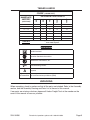
5 INCH BENCH GRINDER
94186
ASSEMBLY AND OPERATING INSTRUCTIONS
Due to continuing improvements, actual product may differ slightly from the product described herein.
3491 Mission Oaks Blvd., Camarillo, CA 93011
Visit our Web site at http://www.harborfreight.com
Copyright © 2006 by Harbor Freight Tools®. All rights reserved. No portion of this manual or
any artwork contained herein may be reproduced in any shape or form without the express
written consent of Harbor Freight Tools.
For technical questions and replacement parts, please call 1-800-444-3353
Specifications
Item
Description
Motor
1/3 HP (maximum); 120VAC, 60 Hz; 3450 RPM;
Sealed radial armature bearings
Line Cord
3-prong grounded plug, 5.5 feet long, 18 AWG x 3C
Spindle
1/2” x 12 TPI threads; Right side: forward threads;
Left side: reverse threads
Wheel Size
5” Dia.
Switch
Lighted, rocker type
Grinding Wheels
Once 35 grit and one 60 grit aluminum oxide
Overall Dimensions
5-3/4” L x 10-1/2” W x 7” H
Rest Dimensions
1” L x 2” W x 2-1/2” H; Brackets: 2-1/2” H x 3-1/2”;
Eye shields: 3-3/4” W x 1/8” Thick
Weight
9.1 lb.
233988
Save This Manual
You will need the manual for the safety warnings and precautions, assembly instructions,
operating and maintenance procedures, parts list and diagram. Keep your invoice with this
manual. Write the invoice number on the inside of the front cover. Keep the manual and
invoice in a safe and dry place for future reference.
General Safety Rules
WARNING!
READ AND UNDERSTAND ALL INSTRUCTIONS. Failure to follow all instructions
listed below may result in electric shock, fire, and/or serious injury.
SAVE THESE INSTRUCTION
Work Area
1.
Keep your work area clean and well lit. Cluttered benches and dark areas invite
accidents.
2.
Do not operate power tools in explosive atmospheres, such as in the presence
of flammable liquids, gases, or dust. Power tools create sparks which may ignite
the dust or fumes.
3.
Keep bystanders, children, and visitors away while operating a power tool.
Distractions can cause you to lose control. Protect others in the work area from
debris such as chips and sparks. Provide barriers or shields as needed.
REV 06f; 09a
SKU 94186 For technical questions, please call 1-800-444-3353
Page 2
Electrical Safety
4.
Avoid body contact with grounded surfaces such as pipes, radiators, ranges,
and refrigerators. There is an increased risk of electric shock if your body is
grounded.
5.
Do not expose power tools to rain or wet conditions. Water entering a power tool
will increase the risk of electric shock.
6.
Grounded tools must be plugged into an outlet properly installed and grounded
in accordance with all codes and ordinances. Never remove the grounding
prong or modify the plug in any way. Do not use any adapter plugs. Check with
a qualified electrician if you are in doubt as to whether the outlet is properly
grounded. If the tools should electrically malfunction or break down, grounding
provides a low resistance path to carry electricity away from the user.
7.
Double insulated tools are equipped with a polarized plug (one blade is wider
than the other). This plug will fit in a polarized outlet only one way. If the plug
does not fit fully in the outlet, reverse the plug. If it still does not fit, contact a
qualified electrician to install a polarized outlet. Do not change the plug in any
way. Double insulation
eliminates the need for the three wire grounded power
cord and grounded power supply system.
8.
Do not abuse the Power Cord. Never use the Power Cord to carry the tools or
pull the Plug from an outlet. Keep the Power Cord away from heat, oil, sharp
edges, or moving parts. Replace damaged Power Cords immediately. Damaged
Power Cords increase the risk of electric shock.
9.
When operating a power tool outside, use an outdoor extension cord marked
“W-A” or “W”. These extension cords are rated for outdoor use, and reduce the risk
of electric shock.
Personal Safety
10. Stay alert. Watch what you are doing, and use common sense when operating a
power tool. Do not use a power tool while tired or under the influence of drugs,
alcohol, or medication. A moment of inattention while operating power tools may
result in serious personal injury.
11. Dress properly. Do not wear loose clothing or jewelry. Contain long hair. Keep
your hair, clothing, and gloves away from moving parts. Loose clothes, jewelry, or
long hair can be caught in moving parts.
12. Avoid accidental starting. Be sure the Power Switch is off before plugging in.
Carrying power tools with your finger on the Power Switch, or plugging in power tools
with the Power Switch on, invites accidents.
13. Remove adjusting keys or wrenches before turning the power tool on. A wrench
or a key that is left attached to a rotating part of the power tool may result in personal
injury.
SKU 94186 For technical questions, please call 1-800-444-3353
Page 3
14. Do not overreach. Keep proper footing and balance at all times. Proper footing
and balance enables better control of the power tool in unexpected situations.
15. Use safety equipment. Always wear eye protection. Dust mask, non-skid safety
shoes, hard hat, or hearing protection must be used for appropriate conditions.
Tool Use and Care
16. Do not force the tool. Use the correct tool for your application. The correct tool
will do the job better and safer at the rate for which it is designed.
17. Do not use the power tool if the Power Switch does not turn it on or off. Any tool
that cannot be controlled with the Power Switch is dangerous and must be replaced.
18. Disconnect the Power Cord Plug from the power source before making any
adjustments, changing accessories, or storing the tool. Such preventive safety
measures reduce the risk of starting the tool accidentally.
19. Store idle tools out of reach of children and other untrained persons. Tools are
dangerous in the hands of untrained users.
20. Maintain tools with care. Keep cutting tools sharp and clean. Properly
maintained tools with a sharp cutting edge are less likely to bind and are easier to
control. Do not use a damaged tool. Tag damaged tools “Do not use” until repaired.
21. Check for misalignment or binding of moving parts, breakage of parts, and any
other condition that may affect the tool’s operation. If damaged, have the tool
serviced before using. Many accidents are caused by poorly maintained tools.
22. Use only accessories that are recommended by the manufacturer for your
model. Accessories that may be suitable for one tool may become hazardous when
used on another tool.
Service
23. Tool service must be performed only by qualified repair personnel. Service or
maintenance performed by unqualified personnel could result in a risk of injury.
24. When servicing a tool, use only identical replacement parts. Follow instructions
in the “Inspection, Maintenance, And Cleaning” section of this manual. Use of
unauthorized parts or failure to follow maintenance instructions may create a risk of
electric shock or injury.
Note: Performance of this tool may vary depending on variations in local line voltage. Extension cord usage may also affect tool performance.
Safety Instructions for Bench Grinder
1.
Maintain labels and nameplates on the Bench Grinder. These carry important
information. If unreadable or missing, contact Harbor Freight Tools for a replacement.
SKU 94186 For technical questions, please call 1-800-444-3353
Page 4
2.
Always wear ANSI-approved safety impact eye goggles and heavy work gloves
when using the Bench Grinder. Using personal safety devices reduce the risk for
injury. Safety impact eye goggles and heavy work gloves are available from Harbor
Freight Tools.
3.
Maintain a safe working environment. Keep the work area well lit. Make sure there
is adequate surrounding workspace. Always keep the work area free of obstructions,
grease, oil, trash, and other debris. Do not use a power tool in areas near flammable
chemicals, dusts, and vapors. Do not use this product in a damp or wet location.
4.
Avoid unintentional starting. Make sure you are prepared to begin work before
turning on the Bench Grinder.
5.
Do not force the Bench Grinder. This tool will do the work better and safer at the
speed and capacity for which it was designed.
6.
Always unplug the Bench Grinder from its electrical outlet before performing
any inspection, maintenance, or cleaning procedures.
7.
Never leave the Bench Grinder unattended while running. Turn power off if you
have to leave the Bench Grinder.
8.
Before each use, check all nuts, bolts, and screws for tightness. Vibration during
mixing may cause these to loosen.
9.
Keep extension cord off the ground and away from water.
10. Always connect the Line Cord to a Ground Fault Circuit Interrupter (GFCI)
protected electrical outlet.
11. Install this product on a proper surface. Locate on a flat, level, and solid surface
that is capable of supporting the weight of the Bench Grinder.
12. Use a full face mask when grinding any metals. The grinder can produce sparks
which may land on your clothing, or hit your face. Also ensure that you are not
operating the grinder around flammable materials or liquids. Always make sure the
safety shields and wheel guards are in place at all times.
13. Make sure the grinding wheels are of the proper speed (3450 RPM or greater)
rating.
14. Frequently quench the workpiece in water to prevent overheating.
15. Use the tool rest to steady the work piece. If the tool rest is not used, the torque of
the spinning grinding wheel may pull the workpiece from your hands.
16. Do not use aluminum oxide wheels when grinding nonferrous metals such as
aluminum and brass. Use silicon carbide wheels for nonferrous metals.
17. When buffing material, always hold the material on the lower side of the buffing
wheel.
SKU 94186 For technical questions, please call 1-800-444-3353
Page 5
WARNING!
People with pacemakers should consult their physician(s) before using this
product. Operation of electrical equipment in close proximity to a heart
pacemaker could cause interference or failure of the pacemaker.
Some dust created by power sanding, sawing, grinding, drilling, and other
construction activities, contain chemicals known (to the State of California)
to cause cancer, birth defects or other reproductive harm. Some examples
of these chemicals are: lead from lead-based paints, crystalline silica from
bricks and cement or other masonry products, arsenic and chromium from
chemically treated lumber. Your risk from these exposures varies, depending
on how often you do this type of work. To reduce your exposure to these
chemicals: work in a well ventilated area, and work with approved safety
equipment, such as those dust masks that are specially designed to filter out
microscopic particles. (California Health & Safety Code 25249.5, et seq.)
Grounding
WARNING!
Improperly connecting the grounding wire can result in the risk of electric
shock. Check with a qualified electrician if you are in doubt as to whether
the outlet is properly grounded. Do not modify the power cord plug provided
with the tool or product. Never remove the grounding prong from the plug.
Do not use the tool if the power cord or plug is damaged. If damaged, have
it repaired by a service facility before use. If the plug will not fit the outlet,
have a proper outlet installed by a qualified electrician.
Grounded Tools with Three Prong Plugs
The Bench Grinder comes with a 3-prong grounded plug.
1.
Tools marked with “Grounding Required” have a three wire cord and three prong
grounding plug. The plug must be connected to a properly grounded outlet. If the tool
should electrically malfunction or break down, grounding provides a low resistance
path to carry electricity away from the user, reducing the risk of electric shock. (See
Figure A.)
2.
The grounding prong in the plug is connected through the green wire inside the cord
to the grounding system in the tool. The green wire in the cord must be the only
wire connected to the tool’s grounding system and must never be attached to an
electrically “live” terminal. (See Figure A.)
3.
Your tool must be plugged into an appropriate outlet, properly installed and grounded
in accordance with all codes and ordinances. The plug and outlet should look like
those in the following illustration. (See Figure A.)
SKU 94186 For technical questions, please call 1-800-444-3353
Page 6
Figure A
Figure B
Double Insulated Tools with Two Prong Plugs
4.A polarized plug (one blade is wider than the other) is a feature to reduce the risk
of electric shock. This plug will fit in a polarized outlet only one way. If the plug does
not fit fully in the outlet, reverse the plug. If it still does not fit, contact a qualified
electrician. Never use with an extension cord unless plug can be fully inserted. Do not
alter the plug.”
5.
Tools marked “Double Insulated” do not require grounding. They have a special
double insulation system which satisfies OSHA requirements and complies with
the applicable standards of Underwriters Laboratories, Inc., the Canadian Standard
Association, and the National Electrical Code. (See Figure B above.)
6.Double insulated tools may be used in either of the 120 volt outlets shown in the
following illustration. (See Figure B above.)
Extension Cords
1.
Grounded tools require a three wire extension cord. Double Insulated tools can use
either a two or three wire extension cord.
2.As the distance from the supply outlet increases, you must use a heavier gauge
extension cord. Using extension cords with inadequately sized wire causes a serious
drop in voltage, resulting in loss of power and possible tool damage. (See Table A.)
3.
The smaller the gauge number of the wire, the greater the capacity of the cord. For
example, a 14 gauge cord can carry a higher current than a 16 gauge cord. (See
Table A.)
4.
When using more than one extension cord to make up the total length, make sure
each cord contains at least the minimum wire size required. (See Table A.)
5.If you are using one extension cord for more than one tool, add the nameplate
amperes and use the sum to determine the required minimum cord size. (Table A.)
6.If you are using an extension cord outdoors, make sure it is marked with the suffix “WA” (“W” in Canada) to indicate it is acceptable for outdoor use.
7.
Make sure your extension cord is properly wired and in good electrical condition.
Always replace a damaged extension cord or have it repaired by a qualified electrician
before using it.
8.
Protect your extension cords from sharp objects, excessive heat, and damp or wet
areas.
SKU 94186 For technical questions, please call 1-800-444-3353
Page 7
TABLES A and B
RECOMMENDED MINIMUM WIRE GAUGE FOR EXTENSION
CORDS* (120/240 VOLT)
(at full load)
50’
75’
100’
150’
EXTENSION CORD LENGTH
25’
NAMEPLATE
AMPERES
0 – 2.0
18
18
18
18
16
2.1 – 3.4
18
18
18
16
14
3.5 – 5.0
18
18
16
14
12
5.1 – 7.0
18
16
14
12
12
7.1 – 12.0
18
14
12
10
-
12.1 – 16.0
14
12
10
-
-
16.1 – 20.0
12
10
-
-
-
TABLE A
* Based on limiting the line voltage drop to five volts at 150%
of the rated amperes.
Symbology
Double Insulated
Canadian Standards Association
Underwriters Laboratories, Inc.
V~
A
Volts Alternating Current
Amperes
n0 xxxx/min. No Load Revolutions per Minute (RPM)
Unpacking
When unpacking, check to make sure that all the parts are included. Refer to the Assembly
section, and the Assembly Drawing and Parts List at the end of this manual.
If any parts are missing or broken, please call Harbor Freight Tools at the number on the
cover of this manual as soon as possible.
SKU 94186 For technical questions, please call 1-800-444-3353
Page 8
Assembly Instructions
1.
Mount the right Tool Rest (23) to the right Wheel Guard (7) using Bolt (21) and
Washer (20).
2.
Mount the left Tool Rest (22) to the left Wheel Guard (7) using Bolt (21) and Washer
(20). See photo below.
3.Adjust each Tool Rest so that there is 1/16 inch (minimum) clearance from the
Grinding Wheel. At the same time, adjust each Tool Rest so that the workpiece
contacts the Grinding Wheel slightly above the center-line of the Motor Rotor (14).
Securely tighten both Tool Rests.
Hex Screw (18)
Eye Shield
Eye Shield
Spark Arrester (18-2)
Cover (2)
Tool Rest, Right (23)
Tool Rest, Left (22)
Wheel Guard (7)
Bolt (21) and Washer (20)
Mounting Hole x 4
Base (33)
4.Attach the Left Spark Arrester (18-3) to the top-left Wheel Guard (7) using Washer
(18-1) and Hex Screw (18). Adjust Spark Arrestor to no closer than 1/16” to the
Grinding Wheel. Tighten Hex Screw (18). Do the same with the Right Spark Arrestor
(18-2).
5.
Mount the right Eye Shield (19), secured to the Right Bracket (17), to the Wheel
Guard (7) using Hex Screw (18). See photo above. Adjust to the desired eye
protection level and securely tighten Hex Screw (18).
6.
Mount the left Eye Shield (19), secured to the Left Bracket (16), to the Wheel Guard
(7) using Hex Screw (18). Adjust to the desired eye protection level and securely
tighten Hex Screw (18).
Bench Mounting
1.Select a sturdy work bench able to withstand the weight of the Bench Grinder and the
workpiece pressure exerted by the operator.
2.
When the mounting location of the Bench Grinder is located, place a marker through
each of the Base (33) mounting holes.
3.
Move the Bench Grinder aside and drill four 1/4 inch mounting holes into the
workbench.
4.
Place Bolts (not supplied) through the Base (33) mounting holes and secure to the
workbench using hardware (not supplied).
SKU 94186 For technical questions, please call 1-800-444-3353
Page 9
Operating Instructions
WARNING!
The grinding wheel can fly apart and cause injury. Grinding wheels must
always be checked for cracks or imperfections. This is done with the “ring
test”. With the Grinding Wheel mounted, tap the wheel gently near the outer
rim with the handle of a screwdriver. You should hear a clear bell-like ring.
If a dull thud occurs, do not use the wheel. The wheel may be damaged and
could come apart during operation.
1.Insert the Line Cord (28) into a grounded electrical outlet.
2.
To turn on the Bench Grinder, press the Switch (27) to the (I) ON position. The motor
will start. See photo on page 9.
3.
Put on the ANSI-approved safety impact glasses and full face shield.
Note: Do not use aluminum oxide grinding wheels when grinding nonferrous metals such as
aluminum and brass. Use silicon carbide grinding wheels for nonferrous metals.
Note: Do not grind with the sides of the grinding wheel.
4. When the Motor reaches full speed, bring the workpiece into the wheel gently, without
jarring.
The workpiece will quickly become heated, therefore frequent quenching in water
is required. When grinding high speed steels such as drill and tool bits, avoid high
temperature buildup as this can affect the temper of the steel.
For small workpieces such as drill bits or chisels, avoid applying pressure to the
Grinding Wheel at a high angle that could cause the workpiece to become lodged
between the Tool Rest and the Grinding Wheel.
5.
To turn off the Bench Grinder, press the Switch (27) to the (O) OFF position.
INSPECTION, MAINTENANCE, AND CLEANING
WARNING!
Make sure the Power Switch of the Bench Grinder is in its “OFF” position
and that the tool is unplugged from its electrical outlet before performing any
inspection, maintenance, or cleaning procedures.
1.
Before each use, inspect the general condition of the Bench Grinder Check for
loose screws, misalignment or binding of moving parts, cracked or broken parts,
damaged electrical wiring, and any other condition that may affect its safe operation.
If abnormal noise or vibration occurs, have the problem corrected before further use.
Do not use damaged equipment.
2.
Periodically recheck all nuts, bolts, and screws for tightness.
3.Store in a clean and dry location.
SKU 94186 For technical questions, please call 1-800-444-3353
Page 10
Dressing the Grinding Wheel
New grinding wheels frequently are not true and during operation will often become
grooved, glazed (build up), out of round, or misshapen. You will need a grinding wheel
dresser (not provided) for this operation. Dressers are available from Harbor Freight Tools.
To dress the grinding wheel:
1.Stand to the side of the wheel for this operation.
2.If the grinding wheel is new, let it run for a minute with no load. If the grinding wheel
runs straight and true, you will not need to dress it prior to operation. If it does not,
proceed with the following instructions.
3.If you are using a “pistol grip” dresser, grip the handle firmly with one hand and the
arm of the dresser with the other. Allow the wheel to reach full speed. Use the tool
rest to support your hand and the dresser, and evenly apply the dresser to all surfaces
of the wheel. The wheel can be dressed in a few minutes.
4.If you are using an “in-line” dresser, hold the handle firmly, put the dresser on the tool
rest so that its wheels can move freely (i.e., the exposed part of the wheel should be
facing up). Let the wheel reach full speed and apply the dresser evenly to all surfaces.
Changing Grinding Wheels
1. Unplug the Bench Grinder from the electrical outlet.
2.Remove three Screws holding the Cover (2). Set aside Cover and Screws.
3.Loosen Hex Screw (18) and move the Eye Shield above the Grinding Wheel.
4.Remove the Tool Rest from the Wheel Guard (7) by removing Bolt (21) and Washer
(20).
5. While holding the Motor Rotor (14) in place with a large, flat blade screwdriver,
turn the Nut (3) clockwise to loosen and remove Grinding Wheel and Flange (4). If
removing the right Grinding Wheel, turn the Nut (3) counterclockwise to loosen and
remove.
6.Replace Grinding Wheel with a new one rated to run to at least to the maximum
speed of the Bench Grinder. See Grinding Wheel Specifications on page 2. Securely
tighten Nut (3).
Loosen Nut (3)
Clockwise
SKU 94186 CAUTION: Using a Grinding Wheel
not rated to run at least to 3450
RPM could cause it to fly apart,
causing injury, or damage to the
Bench Grinder.
For technical questions, please call 1-800-444-3353
Page 11
Parts List
Part #
Description
1
Screw
2
Cover
3
Nut
4
Range
5
Grinding Wheel, 60 Grit
6
Screw
7
Wheel Guard
8
Screw
9
Motor Housing
10
Ball Bearing
11
Nut
12
Motor Stator
13
Nut
14
Motor Rotor
15
Screw
16
Bracket, Left
17
Bracket, Right
18
Hex Screw
18-1
Washer
18-2
Spark Arrestor, Right
18-3
Spark Arrestor, Left
19
Eye Shield
20
Washer
20-1
Spring Washer
21
Bolt
22
Tool Rest, Adjustable Left
23
Tool Rest, Adjustable Right
24
Strain Relief
25
Grinding Wheel, 36 Grit
26
Motor Housing
27
Switch
28
Line Cord
29
Base Plate
30
Condenser
31
Screw
32
Pad
33
Base
NOTE: Some parts are listed and shown for illustration purposes only and are not available individually as replacement parts.
REV 09a
SKU 94186 For technical questions, please call 1-800-444-3353
Page 12
Assembly Drawing
20-1
PLEASE READ THE FOLLOWING CAREFULLY
THE MANUFACTURER AND/OR DISTRIBUTOR HAS PROVIDED THE PARTS DIAGRAM
IN THIS MANUAL AS A REFERENCE TOOL ONLY. NEITHER THE MANUFACTURER
NOR DISTRIBUTOR MAKES ANY REPRESENTATION OR WARRANTY OF ANY KIND
TO THE BUYER THAT HE OR SHE IS QUALIFIED TO MAKE ANY REPAIRS TO THE
PRODUCT OR THAT HE OR SHE IS QUALIFIED TO REPLACE ANY PARTS OF THE
PRODUCT. IN FACT, THE MANUFACTURER AND/OR DISTRIBUTOR EXPRESSLY
STATES THAT ALL REPAIRS AND PARTS REPLACEMENTS SHOULD BE UNDERTAKEN
BY CERTIFIED AND LICENSED TECHNICIANS AND NOT BY THE BUYER. THE BUYER
ASSUMES ALL RISK AND LIABILITY ARISING OUT OF HIS OR HER REPAIRS TO THE
ORIGINAL PRODUCT OR REPLACEMENT PARTS THERETO, OR ARISING OUT OF
HIS OR HER INSTALLATION OF REPLACEMENT PARTS THERETO.
REV 09a
SKU 94186 For technical questions, please call 1-800-444-3353
Page 13
LIMITED 90 DAY WARRANTY
Harbor Freight Tools Co. makes every effort to assure that its products meet high
quality and durability standards, and warrants to the original purchaser that this product
is free from defects in materials and workmanship for the period of 90 days from the date
of purchase. This warranty does not apply to damage due directly or indirectly, to misuse,
abuse, negligence or accidents, repairs or alterations outside our facilities, criminal activity,
improper installation, normal wear and tear, or to lack of maintenance. We shall in no event
be liable for death, injuries to persons or property, or for incidental, contingent, special or
consequential damages arising from the use of our product. Some states do not allow the
exclusion or limitation of incidental or consequential damages, so the above limitation of
exclusion may not apply to you. This warranty is expressly in lieu of all other warranties, express or implied, including the warranties of merchantability and fitness.
To take advantage of this warranty, the product or part must be returned to us with
transportation charges prepaid. Proof of purchase date and an explanation of the complaint
must accompany the merchandise. If our inspection verifies the defect, we will either repair
or replace the product at our election or we may elect to refund the purchase price if we
cannot readily and quickly provide you with a replacement. We will return repaired products at our expense, but if we determine there is no defect, or that the defect resulted from
causes not within the scope of our warranty, then you must bear the cost of returning the
product.
This warranty gives you specific legal rights and you may also have other rights
which vary from state to state.
3491 Mission Oaks Blvd. • PO Box 6009 • Camarillo, CA 93011 • (800) 444-3353
SKU 94186 For technical questions, please call 1-800-444-3353
Page 14