1
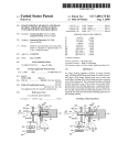
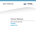
3-INCH MUL
TIPURPOSE
MULTIPURPOSE
BENCH GRINDER
43533
ASSEMBLY AND OPERATING INSTRUCTIONS
3491 Mission Oaks Blvd., Camarillo, CA 93011
Visit our Web site at http://www.harborfreight.com
Copyright © 2000 by Harbor Freight Tools. All rights reserved. No portion of this
manual or any artwork contained herein may be reproduced in any shape or form
without the express written consent of Harbor Freight Tools.
For technical questions and replacement parts, please call 1-800-444-3353
Specifications
ITEM
DESCRIPTION
Motor
110 VAC, 60 Hz, single phase, 120 watts,
0.5 amps (star tup), 0.3 amps (no load),
0.5 amps (with load)
No Load RPM
0 to 20,000 RPM
Line Cord
5 feet, 3-prong ground
Grinding Wheels
1- 3 x 3/4 inch Grinding Stone
1- 3 x 3/4 inch Fiber Wheel
Arbor
0.39 inches (10 mm) diameter
Flex Shaft
31 inches long
Flex Shaft Collet
1/8 inch diameter
Flex Shaft Bit
1/8 inch mounting stone
Features
Variable Speed Dial
Flex shaft wrench set
Save This Manual
You will need the manual for the safety warnings and precautions, assembly
instructions, operating and maintenance procedures, parts list and diagram. Keep
your invoice with this manual. Write the invoice number on the inside of the front
cover. Keep the manual and invoice in a safe and dry place for future reference.
Safety Warnings and Precautions
WARNING: When using tool, basic safety precautions should always be followed to reduce the risk of personal injury and damage to equipment.
Read all instructions before using this product!
1.
Avoid working alone. If an accident happens, an assistant can bring help.
2.
Disconnect power. Unplug tool when not in use, before servicing and when
changing accessories such as grinding wheels. Never walk away and leave
the tool running.
3.
Keep work area clean. Cluttered areas invite injuries.
4.
Keep children away. Children must never be allowed in the work area. Do
not let them handle machines, tools, or extension cords.
SKU 43533
Page 2
5.
Store idle equipment. When not in use, tools must be stored in a dry
location to inhibit rust. Always lock up tools and keep out of reach of children.
6.
Dress properly. Do not wear loose clothing or jewelry as they can be caught
in moving parts. Protective, electrically nonconductive clothes and nonskid
footwear are recommended when working. Wear restrictive hair covering to
contain long hair. Wear an ANSI approved dust mask or respirator.
7.
Use eye protection. Always wear ANSI approved impact safety goggles.
8.
Do not overreach. Keep proper footing and balance at all times. Do not reach
over or across electrical cables or frames.
9.
Maintain tools with care. Inspect grinding wheels for cracks, and tool cords
periodically and, if damaged, have them repaired by an authorized technician.
10. Use the right tool for the job. Do not attempt to force a small tool or
attachment to do the work of a larger industrial tool. There are certain
applications for which this tool was designed. Do not modify this tool and do
not use this tool for a purpose for which it was not intended.
11. Stay alert. Watch what you are doing, use common sense. Do not operate
any tool when you are tired.
12. Check for damaged parts. Before using any tool, any part that appears
damaged should be carefully checked to determine that it will operate
properly and perform its intended function. Check for alignment and binding
of moving parts; any broken parts or mounting fixtures; and any other
condition that may affect proper operation. Any part that is damaged should
be properly repaired or replaced by a qualified technician. Do not use the tool
if any switch does not turn On and Off properly.
13. Replacement parts and accessories. When servicing, use only identical
replacement parts. Use of any other parts will void the warranty. Only use
accessories intended for use with this tool. Approved accessories are
available from Harbor Freight Tools.
14. Do not operate tool if under the influence of alcohol or drugs. Read
warning labels on prescriptions to determine if your judgment or reflexes are
impaired while taking drugs. If there is any doubt, do not operate the tool.
15. Use proper size and type extension cord. If an extension cord is required,
it must be of the proper size and type to supply the correct current to the tool
without heating up. Otherwise, the extension cord could melt and catch fire, or
cause electrical damage to the tool. This tool requires use of an extension
cord of 0 to 10 amps capability (up to 50 feet), with wire size rated at 18
AWG. Longer extension cords require larger size wire. If you are using the
tool outdoors, use an extension cord rated for outdoor use. (signified by “WA”
on the jacket).
SKU 43533
Page 3
16. Take caution as some woods contain preservatives such as copper
chromium arsenate (CCA) which can be toxic. When cutting these materials
extra care should be taken to avoid inhalation and minimize skin contact.
17. Maintenance. For your safety, service and maintenance should be performed
regularly by a qualified technician.
Additional Specific Safety Instructions for Bench Grinders
1.
When grinding any metals, the grinder can produce sparks which may land on
your clothing, or hit your face. You should use a full face mask and
appropriate protective clothing. Also ensure that you are not operating the
grinder around flammable materials or liquids. Always make sure the safety
shields and wheel guards are in place at all times.
2.
Make sure the grinding wheels are of the proper speed (RPM) rating for the
grinder.
3.
Frequently quench the workpiece in water to prevent overheating; be careful
not to get water on the bench grinder.
4.
Use the tool rest to steady the work piece. If the tool rest is not used, the
torque of the spinning grinding wheel may pull the workpiece from your hands.
5.
Do not use aluminum oxide wheels when grinding nonferrous metals such as
aluminum and brass. Use silicon carbide wheels for nonferrous metals.
6.
When buffing material, always hold the material on the lower side of the
buffing wheel. Always keep fingers clear of the grinding wheel and the tool
rest.
Note: Performance of this tool may vary depending on variations in local line voltage.
Extension cord usage may also affect tool performance.
Warning: The warnings, cautions, and instructions discussed in this instruction
manual cannot cover all possible conditions and situations that may occur. It
must be understood by the operator that common sense and caution are factors
which cannot be built into this product, but must be supplied by the operator.
Unpacking
When unpacking, check to make sure the following parts are included.
1) 3-inch Bench Grinder, 2) 31-inch Flex Shaft, 3) Wrench
4) 3-inch Grinder Stone, 5) 3-inch Fiber Wheel, 6) 1/8 inch Mounting Stone Bit
If any parts are missing or broken, please call Harbor Freight Tools at the number
on the cover of this manual.
SKU 43533
Page 4
Operation
Turning the Bench Grinder ON and OFF
1.
Insert the Plug (36) into an electrical
outlet.
2.
Turn the speed control Knob (31)
clockwise to turn the motor ON and
adjust its speed.
3.
To turn OFF, turn the Knob
counterclockwise until it clicks.
4.
Never leave the bench grinder running unattended. Always turn off the tool
when not in use.
Speed Control and
On/Off Knob (31)
Using the Grinder
WARNING: The grinding wheel can fly apart and cause injury.
Grinding wheels must always be checked for cracks or imperfections. This is
done with the “ring test”. Tap the wheel gently near the outer rim with the
handle of a screwdriver. You should hear a clear bell-like ring. If a dull thud
occurs, do not use the wheel. The wheel may be damaged and could come
apart during operation.
1.
Always bring the workpiece into the wheel gently, without jarring.
2.
The workpiece will quickly become heated, therefore frequent quenching in
water is required.
3.
When grinding high speed steels such as drill and tool bits, avoid high
temperature buildup as this can affect the temper of the steel.
4.
For small workpieces such as drill bits or chisels, avoid applying pressure to
the wheel at a high angle that could cause
the workpiece to become lodged between
the tool rest and the wheel.
Wheel Cover (14)
Grinding with the Flex Shaft
1.
Secure the Flexible Shaft (32) to the Wheel
Cover (14).
(37)
Align and insert the shaft. It can only go in
one way.
2.
Tighten the Flexible Shaft Connector Nut
(37) over the Wheel Cover.
SKU 43533
Page 5
Flexible Shaft (32)
3.
Slip off the Chuck Cover (49).
4.
Loosen the Fixing Nut (47) with the Wrench (50).
5.
Insert the Mounted Stone Bit (48) into the Chuck (46) and tighten Fixing Nut.
Mounted Stone Bit (48)
Chuck Cover (49)
Flexible Shaft (32)
Chuck (46)
Fixing Nut (47)
Wrench (50)
6.
Slip the Chuck Cover (49) over the Chuck assembly.
7.
Grasp the Flexible Shaft handle with one hand, and turn the Grinder ON with
the other hand.
CAUTION: Always wear ANSI approved safety glasses when grinding.
8.
When finished, turn the Grinder OFF and wait for it to stop before setting
down the Flexible Shaft.
Maintenance
Dressing the Grinding Wheel
Note: New wheels frequently are not true and during operation will often become
grooved, glazed (build up), out of round, or misshapen. You will need a grinding
wheel dresser for this operation. Dressers are available from Harbor Freight Tools.
1.
Stand to the side of the wheel for this operation.
2.
If the wheel is new let it run for a minute with no load. If the wheel runs
straight and true, you will not need to dress it prior to operation. If it does not,
proceed with the following instructions.
3.
If you are using a “pistol grip” dresser, grip the handle firmly with one hand
and the arm of the dresser with the other. Allow the wheel to reach full
speed. Use the tool rest to support your hand and the dresser, and evenly
apply the dresser to all surfaces of the wheel. The wheel can be dressed in a
few minutes.
4.
If you are using an “inline” dresser, hold the handle firmly, put the dresser on
the tool rest so that its wheels can move freely (i.e., the exposed part of the
wheel should be facing up). Let the wheel reach full speed and apply the
dresser evenly to all surfaces.
SKU 43533
Page 6
Parts List
Item
Description
Qty
Item
Description
Qty
1
Left Nut
1
26
Brush
2
2
Polishing Wheel
1
27
Motor Housing
1
3
Wheel Pushing Ring
4
28
Wheel Cover
1
4
Washer
2
29
Circuit Board
1
5
Bearing
1
30
Base Holder
1
6
Shap Ring
2
31
Knob
1
7
Rotor
1
32
Flexible Shaft
1
8
Armature
1
33
Adaptor
1
9
Fan
1
34
Cord
1
10
Bearing
1
35
Spring
1
11
Sanding Wheel
1
36
Plug
1
12
Right Nut
1
37
Flexible Shaft Connector Nut
1
13
Mounting Nut, Flexible Shaft
1
38
Tool Rest
1
14
Wheel Cover
1
39
Flexible Shaft Hose
1
15
Nut
6
40
Spring
1
16
Bolt
2
41
Chuck Cover
1
17
Wheel Cover
1
42
Bearing
1
18
Clamp
1
43
Washer
1
19
Stator
1
44
Beraing
1
20
Clamp
2
45
Spindle
1
21
Wire Cover
2
46
Chuck
1
22
Brush Holder
1
47
Fixing Nut
1
23
Wire Cover
2
48
Mounted Stone Bit
1
24
Brush Screw
2
49
Chuck Cover
1
25
Brush Spring
2
50
Wrench
1
PLEASE READ THE FOLLOWING CAREFULLY
THE MANUFACTURER AND/OR DISTRIBUTOR HAS PROVIDED THE PARTS DIAGRAM
IN THIS MANUAL AS A REFERENCE TOOL ONLY. NEITHER THE MANUFACTURER NOR
DISTRIBUTOR MAKES ANY REPRESENTATION OR WARRANTY OF ANY KIND TO THE
BUYER THAT HE OR SHE IS QUALIFIED TO MAKE ANY REPAIRS TO THE PRODUCT OR
THAT HE OR SHE IS QUALIFIED TO REPLACE ANY PARTS OF THE PRODUCT. IN FACT,
THE MANUFACTURER AND/OR DISTRIBUTOR EXPRESSLY STATES THat ALL REPAIRS
AND PARTS REPLACEMENTS SHOULD BE UNDERTAKEN BY CERTIFIED AND LICENSED
TECHNICIANS AND NOT BY THE BUYER. THE BUYER ASSUMES ALL RISK AND LIABILITY ARISING OUT OF HIS OR HER REPAIRS TO THE ORIGINAL PRODUCT OR REPLACEMENT PARTS THERETO, OR ARISING OUT OF HIS OR HER INSTALLATION OF REPLACEMENT PARTS THERETO.
SKU 43533
Page 7
Assembly Drawing
NOTE: Some parts are listed and shown for illustration purposes
only and are not available individually as replacement parts.
SKU 43533
Page 8