1
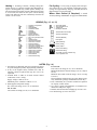
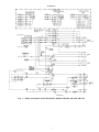
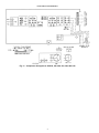
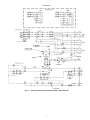
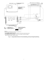
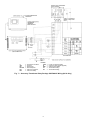
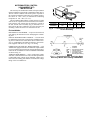
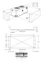
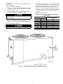
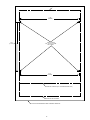
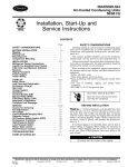
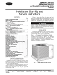
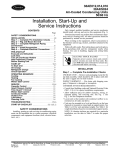
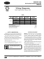
38AKS013-024
Air-Cooled Condensing Units
50/60 Hz
Wiring Diagrams
Units Produced After January 1996
INDEX
UNIT
38AKS
013-024
ELECTRICAL
CHARACTERISTICS
(V-Ph-Hz)
208/230-3-60
380-3-60
230-3-50
346-3-50*
400-3-50
460-3-60
575-3-60
SCHEMATIC
DIAGRAM
FIG. NO.
1
1
1
1
1
3
3
COMPONENT
ARRANGEMENT
FIG. NO.
2
2
2
2
2
4
4
LABEL DIAGRAM
(On Unit)
NO. 38AK
501206
501206
501206
501206
501206
501207
501207
*38AKS024 only.
Remote Thermostat Wiring . . . . . . . . . . . . . . . . . . . . . . . . . . . . . . . . . . . . . . . . . . . . . . . . . .
Programmable Electronic Thermostat Wiring . . . . . . . . . . . . . . . . . . . . . . . . . . . . . . . . . . . . . .
Accessory Transformer Relay Package . . . . . . . . . . . . . . . . . . . . . . . . . . . . . . . . . . . . . . . . .
Accessory Winter Start Package . . . . . . . . . . . . . . . . . . . . . . . . . . . . . . . . . . . . . . . . . . . . . .
Motormaster® Control Diagrams . . . . . . . . . . . . . . . . . . . . . . . . . . . . . . . . . . . . . . . . . . . . . .
. . Fig. 5
. . Fig. 6
. . Fig. 7
. . Fig. 8
Fig. 9-15
SAFETY CONSIDERATIONS
OPERATING SEQUENCE
Installation, start-up, and servicing of this equipment can
be hazardous due to system pressures, electrical components, and equipment location (roofs, elevated structures, etc.)
Only trained, qualified installers and service mechanics
should install, start up, and service this equipment.
When working on the equipment, observe precautions in
the literature, tags, stickers, and labels attached to the equipment, and any other safety precautions that apply.
• Follow all safety codes.
• Wear safety glasses and work gloves.
• Use care in handling, rigging, and setting bulky equipment.
• Use care in handling electronic components.
Cooling — When the first stage (TC1) of the cooling ther-
ELECTRIC SHOCK HAZARD
Open all remote disconnects before servicing
this equipment.
mostat closes, the timer starts. After approximately
3 seconds, the timer activates the compressor and fan
motor no. 1. When the liquid pressure builds to approximately 260 psig (1793 kPa), fan motor no. 2 is energized.
On demand for additional cooling capacity, the second stage
(TC2) of the cooling thermostat closes, energizing a fieldsupplied liquid line solenoid valve (LLSV), which opens.
This increases the suction pressure, causing the compressor
to operate at higher capacity.
When fan switch is set at AUTO, the indoor-air fan cycles
with the compressor. When the switch is set at CONT, the
indoor-air fan runs continuously.
At shutdown, the Time Guard® II timer prevents the compressor from restarting for approximately 5 minutes.
In addition, a field-supplied solenoid valve (locate at fan
coil) wired in parallel with the compressor contactor coil,
shuts off the liquid line to prevent the refrigerant migration
back to the compressor during the off cycle. This valve is
recommended for all installations and is mandatory if piping
length is over 75 ft (22.9 m) or if liquid line diameter exceeds 5⁄8 in. (38AKS013, 014) or 7⁄8 in. (38AKS016, 024). If
two liquid line solenoid valves are used, add accessory relaytransformer package 38AE900001 (60 Hz only).
Manufacturer reserves the right to discontinue, or change at any time, specifications or designs without notice and without incurring obligations.
Book 1 4
PC 111
Catalog No. 563-820
Printed in U.S.A.
Form 38AKS-2W
Pg 1
8-96
Replaces: New
Tab 3a 2a
Heating — If heating is desired, a heating/cooling ther-
Fan Cycling — Fan cycling is employed for head pressure control. The no. 2 fan responds to liquid line pressure,
cycling on at approximately 260 psig (1793 kPa) and off at
approximately 126 psig (869 kPa).
mostat (See Fig. 5-7) must be supplied. This thermostat energizes a field-supplied relay, which operates heating controls and energizes the indoor-fan relay. When the fan switch
is set at AUTO, the indoor-air fan cycles with the heating
control. The indoor-air fan runs continuously when the fan
switch is set at CONT.
Winter Start Control (If Required) — Install
Accessory Package 38AE900021. See page 9 for further details.
LEGEND (Fig. 1-5, 14, 15)
C
CAP
CB
CH
COM
COMP
CR
Du
Equip Gnd
FCPS
FU
HD
HPS
IFC
IP
LLS
LLSV
LPS
NEC
OFC
OFM
OFR
TB
TC
—
—
—
—
—
—
—
—
—
—
—
—
—
—
—
—
—
—
—
—
—
—
—
—
Contactor, Compressor
Capacitor
Circuit Breaker
Crankcase Heater
Common
Compressor
Control Relay
Dummy Terminal
Equipment Ground
Fan Cycling Pressure Stat
Fuse
Heating Device
High-Pressure Switch
Indoor-Fan Contactor
Internal Protector
Liquid Line Solenoid
Liquid Line Solenoid Valve
Low-Pressure Switch
National Electrical Code
Outdoor-Fan Contactor
Outdoor-Fan Motor
Outdoor-Fan Relay
Terminal Block
Thermostat-Cooling
TDR
TGD
TRAN
QT
—
—
—
—
Time Delay Relay
Time Guard® Circuit
Transformer
Quadruple Terminal
Terminal Block Connection
Terminal (Unmarked)
Terminal (Marked)
Field Splice
Splice (Marked)
Factory Wiring
Factory Splice
Field Control Wiring
Field Power Wiring
To indicate common potential only,
not to represent wire.
NOTES (Fig. 1-4)
1. Fan motor(s) are thermally protected. Compressor motors
are protected against primary single-phasing conditions.
2. If any of the original factory installed wire must be
replaced, it must be replaced with type 90 C wire or its
equivalent.
3. Terminal block 2 (TB2) is for field external control
connections, Class 2 wiring:
Supply voltage at TB2 is 24 vac
Maximum power available at TB2 is 31.5 va
4. Field-supplied component ratings:
IFC sealed coil rating (24 vac) 12 va maximum.
For 24-1-50:
LLS sealed coil rating (24 vac) 23 va maximum.
5.
6.
7.
8.
2
For 24-1-60:
LLS sealed coil rating (24 vac) 18 va maximum.
Minimum thermostat electrical rating is 120 va (5 amp at
24 vac).
Minimum fan switch electrical rating is 60 va (2.5 amp
at 24 vac).
If two liquid line solenoid valves are used, add accessory
relay transformer package 38AE900001 (60 Hz only).
LLS, controlled by TC2, activates one-half of evaporator
for capacity control feature.
Use copper, copper-clad aluminum, or aluminum conductors for field power supply.
Insulate unused lead when changing tap for 208 v use.
For field wiring, use 60 C rated wire.
SCHEMATIC
Fig. 1 — Power and Control Circuit Schematics; 208/230, 380-3-60; 230, 346, 400-3-50
3
COMPONENT ARRANGEMENT
Fig. 2 — Component Arrangement; 208/230, 380-3-60; 230, 346, 400-3-50
4
SCHEMATIC
Fig. 3 — Power and Control Circuit Schematics; 460, 575-3-60
5
COMPONENT ARRANGEMENT
Fig. 4 — Component Arrangement; 460, 575-3-60
NOTES:
1. Combination LLSV2 plus IFC va
should not exceed 30 va.
2. Do not exceed 5 va (24 vac)
per coil R1.
}
Use accessory relaytransformer package
38AE900001 if these
va values must be
exceeded.
Fig. 5 — Remote Thermostat Wiring;
2-Step Cooling/2-Step Heating
6
C
HD
IFC
LLSV
—
—
—
—
LEGEND
Compressor Contactor
R —
Heating Device
Indoor Fan Contactor
Liquid Line Solenoid Valve
Heat Control Relay (fieldsupplied, 24-volt sealed coil,
10-va max rating)
Factory Wiring
Field Wiring
NOTES:
1. Combination LLSV2 plus IFC VA should not exceed 30 VA.
2. Do not exceed 5 VA (24 VAC) per coil.
3. If the VA values in Notes 1 and 2 must be exceeded, use accessory relay-transformer package 38AE900001 (60 Hz units only).
4. Wiring diagrams are general guides only and are not intended for a specific installation.
Refer to individual product installation literature.
Fig. 6 — Programmable Electronic Thermostat Wiring; 2-Step Cooling/2-Step Heating
7
LEGEND
C
CM
HD
HT ANT
IFC
IFR
—
—
—
—
—
—
Compressor Contactor
Common
Heat Device
Heat Anticipator
Indoor-Fan Contactor
Indoor-Fan Relay
LLSV
R
SVR
TC
TH
—
—
—
—
—
Liquid Line Solenoid Valve
Accessory Relay (Field-Supplied)
Solenoid Valve Relay
Thermostat Cooling
Thermostat Heating
Fig. 7 — Accessory Transformer Relay Package 38AE900001 Wiring (60 Hz Only)
8
MOTORMASTER® CONTROL
(LOW AMBIENT KIT)
INSTALLATION
LOW-AMBIENT
CONTROL
The accessory low-ambient kit contains a fan speed (Motormaster) control device activated by a temperature sensor (Fig. 8).
The kit controls condenser fan motor speed in response to
the saturated condensing temperature. For outdoor temperatures down to −20 F (−29 C), it maintains the condensing
temperature at 100 610 F (38 66 C).
The low-ambient (Motormaster) control consists of a solidstate circuit on a printed circuit board encased in an aluminum extrusion. The control must be fastened to a panel in
the unit, and the sensor assembly (Fig. 8) mounted to a return bend on the unit’s condenser coil. Parts necessary for
mounting control and sensor are included in the kit.
SENSOR
ASSEMBLY
C
A
B
KIT NO.
32LT900301
32LT900611
VOLTS
All except 460
460
AMPS
8.0
4.0
A
57⁄8
57⁄8
B
63⁄16
73⁄8
C
3 3 ⁄8
3 3 ⁄8
Fig. 8 — Low-Ambient (Motormaster) Control and
Sensor Assembly
Pre-Installation
DISCONNECT UNIT POWER — To prevent electric shock,
open and tag all disconnects before modifying the condensing unit.
INSTALL WINTER START CONTROL — The unit must
be modified for winter start control before installing and using the low-ambient kit. Order Winter Start Control accessory no. 38AE900021 and install according to the instructions supplied with the kit. See Fig. 9 for wiring.
FABRICATE AND INSTALL WIND BAFFLES — The
38AKS units equipped with the low-ambient kit require baffles
to prevent wind crosscurrents from causing abnormal operation as the fan is modulated. Construct and install wind baffles
as shown in Fig. 10.
VERIFY POWER WIRING — Power wiring must comply
with NEC (National Electrical Code) and all requirements.
Confirm that supply voltage meets minimum voltage specified on the unit’s rating plate and that it matches the voltage
rating of the low-ambient kit.
C
HPS
IP
LPS
TDR
—
—
—
—
—
LEGEND
Contactor
High-Pressure Switch
Internal Protector
Low-Pressure Switch
Time-Delay Relay
Field-Supplied Wiring
Fig. 9 — Connection Points, Time-Delay Relay,
Accessory Winter Start Package 38AE900021
9
DIMENSIONS (ft-in.)
BAFFLE LOCATIONS
Right-Hand Side*
Back
Left-Hand Side*
A
2-511⁄16
5-81⁄8
3-07⁄16
*As viewed from access panel side.
Fig. 10 — Wind Baffle Details
10
1. See Fig. 12 to determine where to locate sensor on coil
return bend. As shown in Fig. 13, fasten sensor to return
bend with the supplied screw, plate washers, and nut. See
Table 1 for sensor temperature vs resistance values.
2. Coil and secure excess wire inside the unit near the sensor or next to the low ambient control; provide additional
protection against abrasion or movement of the wire if
necessary.
3. Reinstall the access panel.
Installation — After completing the pre-installation steps,
proceeds as follows:
MOUNT CONTROL ASSEMBLY
1. See Fig. 11 for the location of the access panel and Motormaster® low-ambient control in the bottom of the unit.
Remove the access panel.
2. Using the template supplied in this document, drill pilot
holes for mounting the low-ambient control.
Table 1 — Sensor (Thermistor) Temperature
vs Resistance
When drilling holes, be careful not to damage return coil
bends inside unit.
TEMPERATURE
F
C
60
16
70
21
77
25
80
27
90
32
100
38
110
43
120
49
3. Fasten control to unit with four no. 10 sheet metal screws
and star lockwashers provided. Lockwashers are required to ensure electrical ground with condensing unit.
MOUNT SENSOR ASSEMBLY
The sensor assembly is fragile. Handle with care.
Fig. 11 — Location of Motormaster Low-Ambient Control
11
NOMINAL RESISTANCE
(Ohms)
7750
5900
5000
4650
3650
2875
2275
1850
Blue wire from CAP1 to TRAN2-H2 must be reconnected from CAP1 to field-installed transformer.
VERIFY OPERATION — Turn on the unit power and set
the thermostat below the ambient room temperature. If the
unit is equipped with a Time Guard® II circuit, wait at least
5 minutes.
After the compressor starts, the fan speed is modulated
according to the condensing temperature and then maintained until the set point is achieved.
If fan motor no. 1 does not start, verify the following conditions and correct as necessary:
• Condensing unit power is on.
• Power is present at fan motor relay contacts (or transformer output output when one is installed).
• Sensor wire connections inside the low-ambient control
are tight.
If the preceding conditions are met and fan motor no. 1
still does not start, perform corrective procedures or replace
components as follows:
• Jumper the power wires (BLK-to-BLK) in the Motormaster control. If the motor does not run, check motor wiring and run capacitor. Replace capacitor and motor if necessary. If the motor runs, ensure the fan motor is wired in
series with the control. Refer to Fig. 14.
• If the fan motor runs when connected to the single-phase
voltage supply but does not run when connected in series
with the Motormaster control, AND the return bend where
the sensor is mounted is warm, short the sensor leads (BLUto-RED). If the motor runs, replace the sensor. If the motor does not run, replace the control and sensor assembly.
Fig. 12 — Location of Low-Ambient Kit Sensors
Fig. 13 — Sensor Installation
*Use control part no. 32LT900301 for all unit voltages except 460 V.
Use control part no. 32LT900611 for 460 V units.
INSTALL CONTROL POWER WIRING — Wire the Motormaster® low-ambient control to the unit’s power circuit as
shown in Fig. 14 and 15; refer to the following sections for
various unit voltages.
Fig. 14 — Motormaster Control Power Wiring
for All Units except 575-V
Wire low-ambient control in series with fan motor.
Power wiring must comply with all local and national requirements. All units except 460-v, 3-ph, 60 Hz use Motormaster control, Carrier Part No. 32LT900301. The 460-v units
use Motormaster control, Carrier Part No. 32LT900611.
ALL UNITS EXCEPT 575-3-60 — For these units, without
special transformer, wire Motormaster control to condenser
fan motor circuit as shown in Fig. 14.
575-3-60 UNITS — The 575-v units require a special fieldinstalled transformer and fan motor. Wire special transformer (part no. HT01AH859) and Motormaster control to
special fan motor (part no. HC44VL610) as shown in Fig. 15.
Blue wire from CB1-13 to CAP1 must be reconnected from
CB1-13 to TRAN2-H2.
Fig. 15 — Motormaster Control Power Wiring for 575-V
Units Using 208/230-V Motors
12
TOP OF CONTROL
5 1/2"
[140 MM]
4 1/2"
[114 mm]
DRILL 4 HOLES
.156"-.154" [4 mm] DIAM
NO. 23 DRILL
5 1/2"
[140 MM]
BOTTOM OF CONTROL (ALL VOLTAGES EXCEPT 460V)
BOTTOM OF 460V CONTROL
CUT ALONG SOLID BORDER LINES TO REMOVE TEMPLATE.
13
Copyright 1996 Carrier Corporation
Manufacturer reserves the right to discontinue, or change at any time, specifications or designs without notice and without incurring obligations.
Book 1 4
PC 111
Catalog No. 563-820
Printed in U.S.A.
Form 38AKS-2W
Pg 16
8-96
Replaces: New
Tab 3a 2a