1
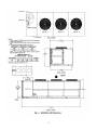
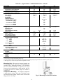
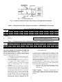
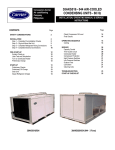
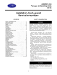
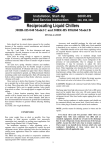
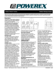
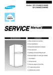
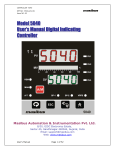
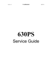
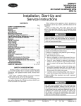
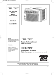
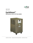
38AKS028-044 Air-Cooled Condensing Units Installation, Start-Up and Service Instructions SAFETY CONSIDERATIONS Installing, starting up, and servicing air-conditioning equipment can be hazardous due to system pressures, electrical components, and equipment location (roofs, elevated structures, etc). Only trained, qualified installers and service mechanics should install, start-up, and service this equipment. Untrained personnel can perform basic maintenance functions such as cleaning coils. All other operations should be performed by trained service personnel. CONTENTS SAFETY CONSIDERATIONS ……………...…….1 BEFORE INSTALLATION ………..……….… 1-6 Placing Unit ……………………………………….. 1 Mounting Unit ……………………………………. 6 Compressor Mounting ………………………….. 6 INSTALLATION ……………………………... 7-10 Refrigerant Piping Connections …………….…. 7 Liquid Solenoid Drop Refrigerant Control .....… 7 Filter Drier and Moisture indicator …………..… 7 Receiver …………………………………………. 7 Piping Procedure ……………………………….. 7 Power Supply …………………………………….8 Power Wiring ……………………………………..9 PRE-START-UP………………………...…… 10-12 System check ………………………………...…. 10 Leak Test and Dehydration ……………………. 10 START-UP …………………………….………12-15 38AKS Units …………………………………….. 13 Sequence of operation …………………………. 14 SERVICE ……………………………………...15-16 38AKS Access for Servicing …………………… 16 TROUBLESHOOTING ………………………… 16 START-UP CHECKLIST ……………… …....18-19 When working on the equipment, observe precautions in the literature and on tags, stickers, and labels attached to the equipment. Follow all safety codes. Wear safety glasses and work when brazing. Use care in handling, rigging and setting bulky equipment. WARNING Before installing or servicing system, always turn off main power to system and install lockout tag on disconnect. There may be more than one disconnect switch. Electrical shock can cause personal injury. BEFORE INSTALLATION Placing Unit – there must be 4 ft (1200 mm) for service and for unrestricted airflow on all sides of unit, and a minimum of 8 ft (2440 mm) clear air space above unit. For multiple units, allow 8 ft (2440 mm) separation between units for airflow and service. See Tables 1A-4B for physical data for unit dimensions. 1 Fig. 1 UNIT 38AKS 028 034 044 MAX SHIPPING WEIGHT lb kg 1924 872 2115 960 2797 1207 B In. 43.0 43.0 49.0 2 CENTER OF GRAVITY C mm In. 1091 28.0 1092 28.0 1245 30.5 mm 711 711 775 3 4 Table 1A – physical Data – 38AKS028-044 Units – 50Hz, English UNIT 38AKS 028 034 044 NOMINAL CAPACITY (tons) OPERATING WEIGHTS (lb) Aluminum-Fin coils (standard) Copper-Fin Coils (optional) REFRIGERANT* Operating Charge, typical (lb)† Shipping Charge (lb) COMPRESSOR QTY … model Oil charge (pt) No. Cylinders Speed (rpm) Capacity Steps (%) Unloader Setting (psig) Unloader No. 1 Load unload Unloader No. 2 Load unload Crankcase Heater Watts CONDENSER FANS QTY… (Rpm) Diameter (in.) Nominal Nominal Airflow (cfm total) Watts (Total) CONDENSER COIL ROWS... Fins/in. Face Area (sq ft total) Storage Capacity (lb)** CONTROLS Pressure stat Settings (psig) high Open Close Low Open Close Oil pressure Switch Open Close FAN CYCLING CONTROLS Operating pressure (psig) No. 2 Fan, Close Open PIPING CONNECTIONS (in. ODM) Suction Liquid Hot Gas 23.4 26.7 35.8 1650 1804 30.5 3 1 … 06E9265 20 6 1490 2 … 19 39.2 37.3 1803 2009 R-22 43.5 4 Reciprocating, Semi-Hermetic 1 … 06E9275 20 6 1450 100, 66, 33 2437 2745 65.0 5 1 … 06E9299 19 6 76 58 78 60 180 Propeller Type – Direct Drive 2 … 950 28 1.0 15.700 1750 Copper Tubes, Aluminum Fins 3 … 17 39.2 56.6 3 … 950 23.700 1520 3 … 17 58.4 84.4 426+7 320+20 27+3 60+5 9 6 255+10 160+10 1⅝ 2⅛ ⅞ ⅝ * Unit is factory supplied with holding charge only. † Typical operation charge with 25 ft of interconnecting piping. Operating charge is approximate for maximum system capacity. ** Storage capacity is 80% full liquid saturated temperature of 125 F. 5 2⅛ Table 1B – physical data – 38AKS028-044 Units – 50Hz,SI UNIT 38AKS NOMINAL CAPACITY (kw) OPERATING WEIGHTS (kg) Aluminum-fin Coils (standard) Copper-Fin Coils (optional) REFRIGERANT* Operating charge, Typical (kg)† COMPRESSOR Qty … Model Oil charge (L) No. Cylinders Speed (r/s) Capacity Steps (%) Unloader Settings (kpag) Unloader No. 1 Load Unload Unloader No. 2 Load Unload Crankcase heater Watts CONDENSER FANS Qty … r/s Diameters (mm) Nominal Hp Nominal Airflow (L/S total) Watts (Total) CONDENSER COIL Rows … Fins/m Face Area (Sq m total) Storage Capacity (kg)** CONTROLS Pressurestat Settings (kpag) High Open Close Low Open Close Oil pressure Switch Open Open FAN CYCLING CONTROLS Operating pressure (kpag) No. 2 Fan, Close Open PRESSURE RELIEF Location Temperature (C) PIPING CONNECTIONS (in, ODM) Suction Liquid Hot Gas 028 82.5 034 94.5 748 818 13.8 1…06E9265 8.99 6 1490 2…748 3.64 17.0 818 911 R-22 19.7 Reciprocating, Semi-Hermetic 1…06E9275 8.99 6 24.2 100, 66, 33 044 127.0 1106 1246 29.5 1…06E9299 9.46 6 524 400 538 414 180 Propeller Type – Direct Drive 2…15.8 762 1.0 7400 1750 Copper Tubes, Aluminum Fins 3…670 3.64 25.7 3…15.8 11.180 1520 3…670 5.43 38.3 293+48 2206+138 186+27 413+103 62 41 1758+69 1103+69 1⅝ 2⅛ ⅞ ⅝ 2⅛ * Unit is factory supplied with holding charge only. † Typical operation charge with 25 ft of interconnecting piping. Operating charge is approximate for maximum system capacity. ** Storage capacity is 80% full liquid saturated temperature of 125 F. Mounting Unit – When unit is in proper location, use of mounting holes in base rails is recommended for securing unit to supporting structure, or for mounting unit on vibration isolators if required, See Fig.4. Fasteners for mounting unit are field supplied. Be sure to mount unit level to ensure proper oil return to compressors. Compressor Mounting – As shipped, compressor is held down by 4 bolts. After unit is installed, loosen each bolt until the sunbber washer can be moved with finger pressure. See Fig.5. Fig.4 – Mounting on Vibration Isolator 6 connections are ready to be made. Pass nitrogen or other inert gas through piping while brazing, to prevent formation of copper oxide. Install field-supplied thermostatic expansion valve (TXV) in liquid line ahead of each evaporator section. TXV-Thermostatic Expansion Valve NOTES: 1. Lower section is first on and last off. 2. For more complete piping information, refer to Carrier system design Manual, part 3, Contact SarmaAfarin After Sale Dept. Fig.5 – Compressor Mounting (Typical unit Shown) INSTALLATION Refrigerant Piping Connections – Line sizes depended on length of piping required between condensing unit and evaporator. See Tables 2-3. it is important to consider liquid lift and compressor oil return. Refer to part 3 of Carrier System design Manual for line sizing information, and Fig. 6-8 for recommended piping details. Liquid Solenoid Drop Refrigerant Control- All units are factory wired to operate on solenoid drop refrigerant control. A field-supplied liquid line solenoid valve (LLSV) must be installed in the liquid line ahead of the indoor coil on 38AH units. See Fig.7. Wires from solenoid valve need to be in conduit as coil voltage is 220v. NOTE: Failure to properly install liquid line solenoid at the indoor unit as described, without Carrier authorization, may VOID warranty. The LLSV field supplied for 38 Aks units. Filter Drier and Moisture Indicator- Every unit should have a filter drier and a sight glass (moisture indicator) field installed. Select the filter drier for maximum unit capacity and minimum pressure drop. Figures 6 and 7 show recommended locations of filter drier(s) and sight glass (es). Complete the refrigerant piping from the evaporator to the condenser before opening the liquid and suction lines at the condensing unit. Receiver – No receiver is provided with the unit: it is recommended that one not be used. Fig.6 – Suction Line Piping to unit with 2-Section Coil Split Piping Procedure – Do not remove run-around pipe from suction and liquid line stubs until piping 7 Fig.7 – Liquid Line Solenoid Valve, Filter Drier(s), and Sight Glass Locations Table 2 – Refrigerant Pipe Sizes, Single suction Risers – 38AKS028-044, 50 Hz Units UNIT 38AKS 16-25(4.9-7.6) L S ⅞ 1⅝ ⅞ 2⅛ ⅞ 2⅛ 028 034 044 LENGTH OF INTERCONNECTING PIPING – FT(m) 25-50(7.9-15.2) 50-75(15.5-22.8) 75-100(23.2-30.5) L S L S L S ⅞ 2⅛* ⅞ 2⅛* ⅞ 2⅛* ⅞ 2⅛ ⅞ 2⅛ 1⅛ 2⅛ ⅞ 2⅛ 1⅛ 2⅝* 1⅛ 2⅝* 100-200(30.8-60.9) L S ⅞ 2⅛* 1⅛ 2⅝* 1⅛ 2⅝* LEGEND L — Liquid line S — Suction line * IMPORTANT: if condensing unit is above air handler, a double suction riser is required. See table below for sizing. Table 3 – Refrigerant Pipe Sizes, Double Suction Risers – 38AKS028-044,50 Hz Units UNIT 38AKS 028 034 044 26-50(7.9-15.2) A B C 1⅝ 1⅝ 2⅛ — — — — — — A 1⅝ — 1⅝ LENGTH OF INTERCONNECTING PIPING – FT(m) 50-75(15.5-22.8) 75-100(23.2-30.5) B C A B 1⅝ 2⅛ 1⅝ 1⅝ — — — — 2⅛ 2⅝ 1⅝ 2⅛ SUCTION PIPING AT EVAPORATOR AND TXV BULB LOCATION (See Fig.7) – The purpose of these recommendations is to achieve good mixing of the refrigerant leaving the evaporator suction head for proper sensing by the TXV bulb. 1. A minimum of two 90 degree elbows must be installed upstream of the expansion valve bulb location. 2. The TXV sensing bulb should be located on a vertical riser where possible. If a horizontal location is necessary. Secure the bulb at approximately the 4 o’clock position. 3. Size the suction line from the evaporator through the riser for high velocity. Suction piping for the high velocity section should be selected for about 0.5˚ F (0.3˚ C) friction loss. If a 2˚ F (1.1˚ C) loss is allowed for the entire suction line. 1.5˚ F (0.8˚ C) is left for the balance of the suction line and it should be sized on that basis. Check that high-velocity sizing is adequate for oil C 2⅛ — 2⅝ A 1⅝ 1⅝ 1⅝ 100-200(30.8-60.9) B C 1⅝ 2⅛ 2⅛ 2⅝ 2⅛ 2⅝ return up the riser. If an oil return connection at the bottom of this suction header is supplied with an evaporator, this connection must be is below the evaporator, the riser at the evaporator does not have to extend as high as the top level of a given evaporator circuit. After a 15diameter riser has been provided, the suction line may elbow down immediately. SAFETY RELIEF – A fusible plug is located on unit liquid line before the liquid valve. Other fusible plugs are located on the compressor(s). 4. Check for leaks. Evacuate and recharge system Recovery, Recycling and Reclamation, and chart on unit. Power Supply – Electrical characteristics of available power supply must agree with unit nameplate rating, Supply voltage must be within limits shown in Table 4 8 IMPORTANT: Operating unit on improper supply voltage, or with excessive phase imbalance, constitutes abuse and may affect Carrier warranty. See Unbalanced 3-phase supply voltage section. Power Wiring – All power wiring must comply with applicable local and national codes. GENERAL WIRING NOTES 1. A crankcase heater is wired in the control circuit so 2. it is always operable as long as power supply disconnect is on, even if any safety device is open or unit stop-start switch is off. It is protected by a 5amp circuit breaker in control power. The power circuit field supply disconnect should be closed except when unit is being serviced. Table 4 – Electrical Data – 38AKS028-044, 50 Hz Units NOMINAL VOLTAGE (v-ph-Hz) 230-3-50 346-3-50 400-3-50 230-3-50 346-3-50 400-3-50 230-3-50 346-3-50 400-3-50 UNIT 38AKS 028 034 044 VOLTAGE RANGE* COMPR FAN MOTOR POWER SUPPLY Min Max RLA LRA QTY FLA(ea) MCA MOCP† 198 311 342 198 311 342 198 311 342 254 380 440 254 380 440 254 380 440 76.9 44.9 43.6 85.9 53.9 50.0 105.1 79.5 65.4 205 155 223 220 176 253 327 240 345 2 2 2 2 2 2 3 3 3 6.4 4.4 3.0 6.4 4.4 3.0 6.4 4.4 3.0 109.0 64.9 60.5 120.2 76.1 68.5 150.6 112.6 90.8 175 100 100 200 125 110 250 175 150 LEGEND NOTES: 230-v and 360-v units are part-wind-start units; the valve under compressor LRA is for the first winding energized. The 400-v units are acress-the line-start units; valve shown is for all windings energized. FLA HACR LRA MCA MOCP — — — — — Full Load Amps Heating, Air Conditioning and Refrigeration Locked Rotor Amps Minimum Circuit Amps per NEC Section 430-24 Maximum Over current protection RLA — Rated Load Amps (compressor) *Units are suitable for use on electrical systems where voltage supplied to unit terminals is not below or above listed minimum and maximum limits. †Fuse or HACR circuit breaker. CONDENSER FANS – The fans must rotate counter clockwise when viewed from above. If necessary, correct direction of fan rotation by interchanging any 2 power input wires at disconnect switch, Affix crankcase heater decal (located in installers packet) to unit disconnect switch. NOTE: For wire runs, use the following sizes of insulated wire. Ft (M) 0-50 50-75 (0-15.2) (15.2-22.9) No. 18 AWG No. 16 AWG (0.82 sq mm) (1.30 sq mm) 35 Min 35 Min LEGND AWG – American wire Gage IMPORTANT: Ensure power to the crankcase heater is always on (except when servicing the unit). If circuit breakers inside unit shut down the compressor and condenser fans, crankcase heater remains on. UNBALANCED 3-PHASE SUPPLY VOLTAGE – Never operate a motor where a phase imbalance in supply voltage is greater than 2% Use the following formula to determine the percent voltage imbalance: % Voltage Imbalance = Max voltage deviation from average voltage 100 × Average voltage Over 75 (Over 22.9) No. 14 AWG (2.08 sq mm) 35 C Min EXAMPLE: Supply voltage is 240-3-60. 9 AB = 243v BC = 236v AC = 238v Average Voltage = 243 + 236 + 238 3 IMPORTANT: Contact your local electric utility company immediately if the supply voltage phase imbalance is more than 2%. = 239 v Determine maximum deviation from average voltage: (AB)243 – 239 = 4v (BC)239 – 236 = 3 v (AC) 239 – 238 = 1v Maximum deviation is 4 v. Determine percent voltage imbalance: 4 Average Voltage = 100 × = 1.7% 239 Table 5 – 38AKS028-044, 50/60 Hzmaximum wire Sizes UNIT 38AKS 028 034 034 V-PH-Hz WIRE SIZE 208/230-3-60 208/230-3-60 230-3-50 208/230-3-60 230-3-50 350 Kcmil This amount of phase imbalance is satisfactory as it is be low the maximum allowable 2%. PRE-START-UP IMPORTANT: Before beginning pre-Start-Up or Start-Up, review Start-Up Checklist at the back of this book. The Checklist assures proper start-up of a unit and provides a record of unit condition. Application requirements, system information, and operation at iniual start-up 6. CATION 9. 7. 8. Do not attempt to start the condensing unit, even momentarily, until the following steps have been completed. Compressor damage may result. 10. System Check 1. Check all air handler(s) and other equipment auxiliary components. Consult the manufactures instructions regarding any other equipment connected to the condensing unit. If unit has field-installed accessories, be sure all are properly installed and correctly wired. 2. Backseat (open) compressor suction and discharge valves. Now close valves one turn to allow refrigerant pressure to reach test gages. 3. Open liquid line service valves. 4. Check tightness of all electrical connections. 5. Compressor oil level should be visible in sight glass. Adjust the oil level as required. No. oil should be removed unless the crankcase heater been energized for at least 24 hours Be sure unit is properly leak checked, dehydrated, and charged. See preliminary Charge, below. Electrical power source must agree with nameplate rating. Crankcase heater must be firmly locked into compressor crankcase. Be sure crankcase is warm (heater must be on for 24 hours before starting compressor). Fan motors are 3-phase. Check rotation of fans during first start-up check. Fan rotation is counterclockwise as viewed from top of unit. If fan is not turning counterclockwise, reverse 2 of the power wires. Be sure compressor floats freely on the mounting springs and that sunbber washers can be moved with finger pressure. See Compressor Mounting section and Fig.5 for loosening compressor bolts. Leak Test and Dehydration – Leak test the entire refrigerant system using soap bubbles and/or an electric leak detector. Evacuate and dehydrate entire refrigerant system by use of methods described in Carrier GTAC II , Module 4, system Dehydration. Preliminary Charge – Refer to Carrier GTAC II, Module 5, charging, Recovery, Recycling, and Reclamation for charging methods and procedures. Charge each system with R-22 by the liquid charging 10 method (through liquid service valve) on the high side. See approximate refrigerant charge in Table 1A-1B. charge according to the valves in the charging Chart, Fig.8-10. Fig. 8- charging chart, 38AKS028, 50/60 Hz Fig.9 – Charging Chart, 38AKS034, 50/60 Hz (Circuits No. 1 and 2) 11 Fig. 10 – Charging Chart, 38AKS044, 50/60 Hz (Circuits No. 1 and 2) START-UP 38AKS Units – close field disconnect. Set thermosetting. Now, only the crankcase heater is energized. After the heater has been on for 24 hours, the unit can be started. If no time has elapsed since the preliminary charge step has been completed, it is unnecessary to wait the 24-hour period. Close the compressor circuit breaker then reset the indoor thermostat below ambient temperature. So that a call for cooling is ensured. NOTE: Do not use the compressor circuit breaker to start and stop compressor, except in an emergency. The start-up of the compressor can occur between 3 seconds and approximately 5 minutes from the time the control circuit is energized due to the anti-short cycle feature of the control module (CM). CHARGE SYSTEM – Actual start-up should be done only under supervision of a qualified refrigeration mechanic. Measure pressure at the liquid line service valve. Also, measure liquid line temperature as close to the liquid service valve as possible. Add or reduce charge until the pressure and temperature conditions of the charging charge curve are met. If liquid pressure and temperature point fall above curve. Add charge, if liquid pressure and temperature point fall below curve, add charge. If liquid pressure and temperature point fall below curve, reduce the charge until the conditions match the curve. CAUTION Never charge liquid into the low-pressure side of system. Do not overcharge. During charging or removal of refrigerant, be sure indoor fan system is operating. CONTROL MODULE (CM) – The unit control module is located in the control section of the control box. The control module performs several functions. 12 COMPLETE UNIT STOPPAGE Causes – Interruption of supplied power, compressor over temperature protection, open HPS, open OPS, or open LPS causes’ compressor stoppage. The LPs is governed by the 3-strile rule, three trip cycles are allowed before the unit is locked out, and the alarm LED will flash a code for the cause of the lockout. Restart – The unit recycles and restarts automatically under the CPM when power is restored or cycled. Complete stoppage of the unit by the CPM, or compressor circuit breaker requires manual resetting of the control circuit. To restart the CPM when the HPS is tripped, it is necessary to interrupt power to the unit, restarting the CPM logic. It is necessary to manually reset the compressor circuit breaker at the unit. If the LPS is not closed within 2½ minutes after compressor starts the compressor and the outdoor fans are shut off. The unit remains off for 3 minutes. After 3 minutes the system is restarted. The PS is again bypassed for 2½ minutes. This cycle will repeat 3 times if the cause of the LPS open is not eliminated. Operation will be locked out after the third cycle unit CPM power is cycled. If sufficient compressor oil pressure has not been built with in 1 minute after the compressor starts, the unit is locked out. The LPS may have to be manually reset at the unit. Power must be cycled to the CPM to reset the controller. previously outlined in Pre-Start-Up section, Leak Test and Dehydration. 8. If any leaks are detected, evacuate and dehydrate as previously outlined in pre-Start-Up section, Leak Test and Dehydration. PRELIMINARY OIL CHARGE – Each compressor is factory charged with oil. When oil is checked at startup, it may be necessary to add or remove oil to bring it to the proper level. One recommended oil level adjustment method is as follows: Add Oil – Close suction service valve and pump down crankcase to 2 psig(14 lpa). (Low-pressure switch must be jumpered.) Wait a few minutes and repeat unit pressure remains steady at 2 psig (14 kpa). Remove oil fill plug above the oil level sight glass, add oil through plug hole, and replace plug. Run compressor for 20 minutes and check oil level. NOTE: Use only Carrier-approved compressor oil. Approved sources are: Texaco, Inc ………………..…………. Capella WF-32 Witco Chemical Crop ………………… Suniso 3GS-A Do not use oil that has been drained out, or oil that has been exposed to atmosphere. Remove Oil – pump down compressor to 2 psig (14 kpa). Loosen the ¼ -in. (6.4mm) pipe plug at the compressor base and allow the oil to seep out the threads of the plug. NOTE: the crankcase will be slightly pressurized. Do not remove the plug, or the entire oil charge will be lost. Small amounts of oil can be removed through the oil pump discharge connection while the compressor is running. START UNIT – The field disconnect is closed, the fan circuit breaker is closed. And the space thermostats are set above ambient so that there is no demand for cooling. Only the crankcase heaters will be energized. Next, close the compressor circuit breakers and then reset space thermostat TC1 below ambient so that a call for stage one cooling is ensured. If compressor does not start, set thermostat lower. NOTE: Do not use circuit breakers to start and stop the compressor except in an emergency. Start-up of circuit no. 1 compressor will be delayed from one second to 5 minutes from the time the call for cooling is initialed. The TC2 (thermostat contacts 2) close 1.5˚ F(0.7˚ C) lower than TC1.After these contacts close, start-up of circuit no. 2 compressor will be delayed from one second to 5 minutes from the time the call for cooling is initiated (see Fig.22), ADJUST REFRIGERANT CHARGE CAUTION If unit or circuit stoppage occurs more than once due to any safety device, the trouble should be corrected before any allempt restart. Compressor crankcase heaters must be on for 24 hours before start-up. To energize the crankcase heaters, set the space thermostat above the ambient so there will be no demand for cooling. Close the field disconnect and turn on the fan circuit breakers. Leave the compressor circuit breakers off/open. The crankcase heaters are now energized. After the heater has been on for 24 hours, the unit can be started. If no time has elapsed since the preliminary charge step has been completed, it is unnecessary to wait the 24-hour period. PRELIMINARY CHECKS 1. Ensure that compressor service valves are back seated. 2. Verify that each compressor floats freely on its mounting springs. 3. Check that electric power supply agrees with unit name plate data. 4. Verify that compressor crankcase heaters are securely in place. 5. Check that compressor crankcase heaters have been on at least 24 hours. 6. Note that compressor oil level is visible in the sight glass. 7. Recheck for leaks using same procedure as CAUTION Never charge liquid into the low-pressure side of system. Do not overcharge. During charging or removal of refrigerant, be sure indoor-fan system is operating.. 13 Return unloader to original setting after checks are complete. FINAL CHECKS – Ensure all safety control are operating. Control panel covers are on, and the service panels are in place. Sequence of Operation 38AKS UNITS – When space thermostat calls for cooling, the no. 1 condenser fan and compressor start after CM valid signal time delay of 7 seconds. If an optional airflow switch is used, compressor and no. 1 condenser fan will not start until sufficient indoor airflow has closed the switch. After 7 seconds the compressor starts and the liquid line solenoid valve for the compressor starts and the liquid line solenoid valve for solenoid drop control opens. The crankcase heater is deener gized, if the head pressure reaches 260 psig (1792 kpa) the second condenser fan starts. Fan no. 3 (38AKS044 only) starts if outdoor ambient air rice above 80F (26.7 C). If cooling demand is low, suction pressure at the compressor drops. As the pressure drops, the compressor unloads 1 or 2 banks of cylinders as required. If cooling demand is high and 2-stage operation is used. The second stage of the thermostat activates the capacity control liquid line solenoid which activates the second stage evaporator coil. The compressor cylinders load or unload in response to compressor suction pressure to meet evaporator load. When the compressor starts , the LPS is bypassed for the first 2 ½ minutes of operation. If the LPS opens after 2 ½ Minutes, the compressor is shut down and cannot restart until the 3 minute anti-short-cycle timer expires. As the space cooling load is satisfied. The second stage of the thermostat opens, and closes the fieldsupplied capacity control liquid line solenoid valve to deavtivate the second stage coil. The compressor adjusts the number of active cylinders to meet the new load. When the space temperature is satisfied, the first stage of the thermostat opens. deenergizing the control relay. The compressor stops and the crankcase heater is energized. Preventing refrigerant migration to the compressor during the off cycle. The liquid line solenoid close (solenoid drop refrigerant control) and the 3 minute compressor anti short-cycle timer is energized. Fig. 11 – Timer Sequence Chart NOTE: Actual start-up and all refrigerant charge modifications should be done only under supervision of a qualified refrigeration technician. With all fans operating. Adjust the refrigerant charge in accordance with the unit charging charts (Fig. 8-10). Measure pressure at the liquid line service valve, being sure Schrader depressor is used if required. Also measure liquid line temperature as close to the liquid service valve as possible. Add charge until the pressure and temperature conditions of the charging chart curve are met. If liquid pressure and temperature point fall above curve, add charge. If liquid pressure and temperature point fall below curve, recover refrigerant to reduce the charge until the conditions match the curve. If the liquid line sight glass is cloudy or shows bubbles in refrigerant. Check refrigerant charge again. Ensure all fans are operating. Also ensure maximum allowable liquid lift has not been exceeded. If charged per chart and if the sight glass is still not clear. Check for a plugged filter drier or a partially closed solenoid valve. Replace or repair. As needed. CHECK COMPRESSOR OIL LEVEL – After adjusting the refrigerant charge, allow each circuit to run fully loaded for 20 minutes. Running oil level should be within view of the crankcase sight glass. Stop the compressors at the field power supply disconnect and check the crankcase oil level. Add oil only if necessary to bring the oil into view in the sight glass. If oil is added, run the circuit for an additional 10 minutes, then stop and check oil level. If the level remains low. Check the piping system for proper design for oil return; also. Check the system for leaks. If the initial check shows too much oil (too high in the sight glass) remove oil to proper level. When the above checks are complete, repeat the procedure with the unit operating at minimum load conditions. For this minimum load check. Operate each circuits compressors individually and unloaded to minimum step. Unload the compressor(s) by turning the control set point adjustment nut counter clock wise until the adjustment nut stops. The unloaded is now at 0 psig (0 kpag) set point. If electric actuated unloaders are installed. Energize the solenoid to unload the compressor. 14 SERVICE (Fig. 12-14) NOTE: Dimension in ( ) is in millimeters. CAUTION Turn off all power to unit before proceeding. 38AKS Units Access for servicing (See Fig.13) COMPRESSOR SECTION – The compressor compartment has 2 side access panel and one front door for servicing, providing access to compressor, all components of the refrigerant system. Electrical controls, and control box. OIL PRESSURE SAFETY SWITCH – Switch is accessed by removing the side access panel on the left side of the unit (as viewed from the compressor end). See Fig. 13. the OPS is found attached to the bottom divider panel. The liquid line service valve can be found behind the side access door on the right side of the until (as viewed from the compressor end). CONDENSER SECTION – Condenser fan motors and fans can be serviced by removal of outlet grilles or side panels. If a fan motor is serviced, be sure the wire fan guard is in place over each fan before starting unit. See Fig.12 for proper fan adjustment. Tighten fan hub securely on motor shaft with setscrew which bears against the key. Be sure to replace Grease over end of motor shaft to protect against moisture causing fan to rust on shaft. Fig. 12 – Location of Prop on Motor Shaft from Outside of Orifice Ring – Typical 38 AKS Unit FAN ADJUSTMENT – Adjust fan as shown in Fig. 12. OIL CHARGE – Compressors are factory charged with oil as follows: COMPRESSOR 06E9265 06E9275 06E9299 Fig. 13 – 38AKS Unit with Access Panels Remove 15 AMOUNT pints (liters) 20.0 (9.4) 20.0 (9.4) 19.0 (9.0) Crankcase Heater – This minimizes absorption of liquid refrigerant by oil crankcase during brief or extended shutdown periods. IMPORTANT: Never open any switch or disconnect that deenegize the crankcase heater unless unit is being serviced or is to be shut down for a prolonged period. After a prolonged shutdown on a service job, energize the crankcase leader for 24 hours before starting the compressor. HIGH-PRESSURE SWITCH – This switch has fixed, non-adjustable settings. Switch is mounted on the compressor. (See Table 15). Fan Cycling – These 38AKS units have standard provision for fully automatic intermediate-season head pressure control through condenser fan cycling; Fan no. 2 is cycled by a fan cycling pressure. The pressure sensor is located in the liquid line of the refrigerant circuit. Fan no. 3 cycling is conrrolled by outdoor-air temperature through an air temperature switch (ATS) (38AKS044 units only). The ATS is located in the lower divider panel between the compressor compartment and condenser section. Through a hole in the panel, the sensing element is exposed to air entering the no. I fan compartment. Fan no. 1 is noncycling. Table 6 shows the operating setting of the FCPS and the ATS. Table 6 – 38AKS Minimum Outdoor-Air Operating Temperature When additional oil or a complete charge is required, use only Carrier-approved compressor oil: Petroleum Specialties Inc ………….……… Cryol 150 Texaco, Inc ………………………..... Cappella WF-32 Witco Chemical Corp …………...………. Suniso 3 Gs IMPORTANT: Do not use drained oil or use oil that has been exposed to atmosphere. Refer to Carrier Training Booklet, GATC II, Module 5, for procedures to add oil. To remove oil, isolate the compressor, reclaim internal compressor charge, and use the compressor drain plug. LIQUID SWHUTOFF/CHARGING VALVE – Valve is located inside the compressor compartment and is provided with ¼-in flare connection for field charging. CAPACITY CONTROL – Capacity control is by 2 suction pressure actuated unloaders. Each controls 2 cylinders. Unloaders are factory set, but may be field adjusted. Number 1 unloader is on cylinder bank on same side of compressor as terminal box. Control Set Point – The control set point (cylinder load point) is adjustable from 0 to 85 psig (0 to 586 kpag). To adjust, turn control set point adjustment nut clock wise to its bottom stop. In this position, set point is 85 psig (586 kpag). Then, turn adjustment counter clock wise to desired control set point. Every full turn counter clock wise decreases set point by 7.5 psig (52 kpag). Pressure Differential – the pressure differential (difference between cylinder load and unload point) is adjustable from 6 to 22 psig (41 to 152 kpag). To adjust, turn pressure differential adjustment screw counterclockwise to its backstop position. In this position, differential is 6 psig (41 kpag). Then, turn adjustment clockwise to desired pressure differential. Every full turn clockwise increases differential by 1.5 psig (10 kpsg). OIL PRESSURE – The OPS in the control circuit stops the compressor and unit, if proper oil pressure differential is not established at start-up or maintained during operation. If OPS stops the unit, determine the cause and correct before restarting unit, Failure to do so will constitute abuse. Equipment failure due to abase may void the warranty. COMPRESSOR PROTECTION Circuit Breaker – Calibrated trip manual reset ambient compensated, magnetic breaker protects against motor overload and locked rotor conditions. Control Module Timer – This control protects compressor against short cycling. See sequence of Operation section. UNIT 38AKS 028 034 044 COMPR CAP. (%) COND TEMP, F(C) 100 67 33 100 67 33 100 67 33 90(32) 80(27) 70(21) 90(32) 80(27) 70(21) 90(32) 80(27) 70(21) MIN OUTDOOR TEMP, F (C) Low Ambient Standard Control Unit (Motor master®) 31(-1) -20(-29) 35(2) -20(-29) 43(6) -20(-29) 30(-1) -20(-29) 34(1) -20(-29) 42(6) -20(-29) 25(-4) -20(-29) 30(-1) -20(-29) 35(2) -20(-29) Table 17 – 38AKS Fan Cycling Controls CONTROL BY Temp, F ( C ) Pressure, Psig (kpa) 16 SWITCH OPENS 70 ± 3 (21 ± 1.7) SWITCH CLOSES 80 ± 3 (27 ± 1.7) 160 ± 10 (1103 ± 69) 255 ±10 (1793 ± 103) TROUBLESHOOTING – 38AKS UNITS SYMPTOM AND PROBABLE CAUSE PROBABLE REMEDY COMPRESSPR DOES NOT RUN 1. Control circuit breaker tripped. 2. Power line open 3. Oil pressure switch tripped. 4. Safety device tripped. 5. Contactor stuck open. 6. Loose terminal connection. 7. Improperly wired controls 8. Seized compressor. 9. 10. 1. 2. 3. 4. 5. 6. 7. 8. Low line voltage. Compressor motor defective. 9. 10. COMPRESSOR STOPS ON LOW-PRESSURE CONTROL 1. Compressor suction shutoff valve partially closed. 2. Low refrigerant charge. 3. Liquid line solenoid valve(s) fails to open. 4. 1. 2. 3. Liquid line shutoff valve closed. COMPRESSORT STOPS ON HIGH-PRESSURE CONTROL 1. Compressor discharge valve partially close. 2. Air in system 3. Condenser fan(s) not operating. 4. System is overcharged UNIT OPERATES TOOLONG ON CONTINOUSLU. 1. Low refrigerant charge. 2. Control contacts fused 3. Air in system 4. Partially plugged expansion valve or filter drier. SYSTEM NOISY 1. Piping vibration. 2. Compressor noisy. COMPRESSOR LOSE OIL 1. Leak in system. 2. Crankcase heaters not energized during shutdown. 3. Improper interconnecting piping design. FROSTED SUCTION LINE Expansion valve admitting excess refrigerant. HOT LIQUID LINE 1. Shortage of refrigerant due to leak. 2. Expansion valve opens too wide. FROSTED LIQUID LINE Restricted filter drier. COMPRESSOR WILL NOT UNLOAD 1. Detective unloader. 2. Detective capacity control solenoid valve. 3. Miswired liquid line solenoid. 4. Weak, broken, or wrong valve body spring. COMPRESSOR WILL NOT LOAD 1. Miswired capacity control liquid solenoid. 2. Detective capacity control solenoid valve. 3. Plugged strainer (high side). 4. Struck or damaged unloader piston or piston ring(s). Reset control circuit breaker. Reset circuit breaker. Reset oil pressure switch at unit. Reset control circuit with thermostat. Replace contactor. Check connections. Check and rewire. Check motor winding for open or short. Replace compressor, it necessary Check line voltage – determine location of Voltage drop and remedy deficiency. Check motor winding for open or short. Replace compressor, if necessary. 4. Open valve. Add refrigerant. Check liquid line solenoid valve for proper Operation. Replace if necessary. Open valve 1. 2. 3. 4. Open valve or replace it detective Purge and evacuates system. Check motor wiring and repair or replace detective. Reclaim charge as needed. 1. 2. 3. 4. Add refrigerant. Replace control. Purge and evacuate system. Clean or replace. 1. 2. Support piping as required. Check valve plates for valve noise. Replace Compressor if bearing is worn. 1. 2. 3. Repair leak. Check wiring and replays. Check heater and replace if defective. Check piping for oil return. Replace if necessary. Adjust expansion valve. 1. 2. Repair leak and recharge. Adjust expansion valve. Remove restriction or replace. 17 1. 2. 3. 4. Replace. Replace valve Rewire correctly. Replace spring. 1. 2. 3. 4. Rewire correctly. Replace valve. Clean or replace strainer. Clean or replace the necessary parts. START-UP CHECKLIST I. PRELIMINARY INFORMATION OUTDOOR: MODEL NO. ……………………………………………. SERIAL NO. ……………………………………… INDOOR: AIR HANDLER MANUFACTURER ……………………………………………..……………………………… MODEL NO. ………………………………………………... SERIAL NO. …………………………………….. ADDITIONAL ACCESSORIES ……………………………………………………………………………………………… II. PRE-START-UP OUTDOOR UNIT IS THERE ANY SHIPPING DAMAGE? ……………………………………...………………. (Y/N) …………………….. ………………………………………………….………………………………………………………………………………… (Y/N) …………………………………………. WILL THIS DAMAGE PREVENT UNIT START-UP? CHECK POWER SUPPLY. DOES IT AGREE WITH UNIT? HAS THE GROUND WIRE BEEN CONNECTION? (Y/N) …………………………………………… HAS THE CIRCUIT PROTECTION BEEN SIZE AND INSTALLED PROPERLY? (Y/N)…………………….. ARE THE POWER WIRES TO THE UNIT SIZED AND INSTALLED PROPERLY? (Y/N) ………………….… HAVE COMPRESSOR HOLDDOWN BOLTS BEEN LOOSENED (Snubber washers are sung, but not tight)?(Y/N) …………… CONTROLS ARE THERMOSTAT AND INDOOR FAN CONTROL WIRING CONNECTIONS MADE AND CHECKED? (Y/N) …………. ARE ALL WIRING TERMINALS (including main power supply) TIGHT? (Y/N) ………………. HAVE CRANKCASE HEATERS BEEN ENERGIZED FOR 24 HOURS? (Y/N) …………….… INDOOR UNIT HAS WATER BEEN PLACED IN DRAIN PAN TO CONFIRM PROPER DRAINAGE? ARE PROPER AIR FILTERS IN PLACE? (Y/N) …………………… (Y/N) ……………….. HAVE FAN AND MOTOR PULLEYS BEEN CHECKED FOR PROPER ALIGNMENT? DO THE FAN BELTS HAVE PROPER TENSION? (Y/N) …………………… HAS CORRECT FAN ROTATION BEEN CONFIRMED? (Y/N) …………………… (Y/N) ………………… PIPING ARE LIQUID LINE SOLENOID VALVES LOCATION AT THE EVAPORATOR COILS AS REQUIRED? (Y/N) … HAVE LEAK CHECKS BEEN MADE AT COMPRESSORS, CONDENSERS, EVAPORATORS, TXVS (thermostatic Expansion Valves), SOLENOID VALVES, FILTER DRIERS, AND FUSIBLE PLUGS WITH A LEAK DETECTOR? (Y/N) ………………….. LOCATE, REPAIR, AND REPORT ANY LEAKS. …………………………………………………………………………. HAVE ALL COMPRESSOR SERVICE VALVES BEEN FULLY OPENED (BACKSEATED)? (Y/N) ………………… HAVE LIQUID LINE SERVICE VALVES BEEN OPENED? (Y/N) ………………………………. 18 IS THE OIL LEVEL IN EACH COMPRESSOR CRANKCASE VISIBLE IN THE COMPRESSOR SIGHT GLASSES? (Y/N) ……………………….. CHECK VOLTAGE IMBALANCE LINE-TO-LINE VOLTS: AB…………….V AC ………………. V BC ……………… V (AB + AC + BC)/3 = AVERAGE VOLTAGE = …………………… V MAXIMUM DEVITION FROM AVERAGE VOLTAGE = ……………………… V VOLTAGE IMBALANCE = 100 × (MAX DEVAITION)/(AVERAGE VOLTAGE) = ……………………. V IF OVER 2% VOLTAGE IMBALANCE, DO NOT ATTEMPT TO START SYSTEM CALL LOCAL POWER COMPANY FOR ASSISTANCE. III. START-UP CHECK EVAPORATOR FAN SPEED AND RECORD. ………………….. CHECK CONDENSER FAN SPEED AND RECORD. ……………………. AFTER LEAST 10 MINUTES RUNNING TIME, RECORD THE FOLLOWING MEASUREMENTS: COMP A1 ………………………….. ………………………….. ………………………….. ………………………….. ………………………….. ………………………….. ………………………….. ………………………….. ………………………….. ………………………….. ………………………….. OIL PRESSURE SUCTION PRESSURE SUCTION LINE TEMP DISCHARGE PRESSURE DISCHARGE LINE TEMP ENTERING CONDENSER AIR TEMP LEAVING CONDENSER AIR TEMP EVAP ENTERING-AIR DB (dry bulb) TEMP EVAP ENTERING-AIR WB (WET BULB) TEMP EVAP LEAVING-AIR DB TEMP EVAP LEAVING-AIR WB TEMP COMP B1 ………………………….. ………………………….. ………………………….. ………………………….. ………………………….. ………………………….. ………………………….. ………………………….. ………………………….. ………………………….. ………………………….. COMPRESSOR AMPS (L1/L2/L3) CHECK THE COMPRESSOR OIL LEVEL SIGHT GLASSES; ARE THE SIGHT GLASSES SHOWING, OIL LEVEL IN VIEW? (Y/N) ………………… NOTE: …………………………………………………………………………………………………………………………………………. …………………………………………………………………………………………………………………………………………. …………………………………………………………………………………………………………………………………………. …………………………………………………………………………………………………………………………………………. …………………………………………………………………………………………………………………………………………. …………………………………………………………………………………………………………………………………………. …………………………………………………………………………………………………………………………………………. …………………………………………………………………………………………………………………………………………. …………………………………………………………………………………………………………………………………………. …………………………………………………………………………………………………………………………………………. …………………………………………………………………………………………………………………………………………. …………………………………………………………………………………………………………………………………………. …………………………………………………………………………………………………………………………………………. 19 Sanaye Sarma Afarin Iran شرکت صنایع سرماآفریه ایران (کریرترموفریک ) NO.200, W. Khorramshahr (Apadana)Ave.,TEHRAN-15337,P.O.BOX: 13145-1799 Tel:88762038 Fax:88762033 سهرودی شمالی ،خیابان خرمشهر ،شماره ،022تهران ،73551-صندوق پستی 75733 -7111:تلفه 88120258:فاکس88120255: 20