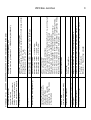
1
l
a
u
n
a
M
s
’
r
e
s
U
[
MSD100
MSD100AES/SA
MSD100T/SA
MASTER STEREO DISPLAY
www.dk-audio.com
]
MSD100 Series - User’s Manual
Copyright © 1995, 1997, 2002, DK-Audio, Herlev
All rights reserved. No part of this publication may be
reproduced or distributed in any form, or by any means,
without prior written consent from DK-Audio A/S,
Denmark.
Trademarks
Analog Devices is a registered trademark of
Analog Devices, Inc. USA
Crystal is a registered trademark of
Crystal Semiconductor Corp., USA
Note: This manual covers all MSD100 Series models.
The main text refers to the MSD100 but applies to all
models. Special notes, subsections and tables are provided to describe operational features that are unique to
specific models.
MSD100 Series - User’s Manual
CONTENTS
1. Introduction
1.1
1.2
1.3
1.4
Using This Manual . . . .
Notation Conventions .
Related Documentation
If You Need Help . . . . .
.
.
.
.
.
.
.
.
.
.
.
.
.
.
.
.
.
.
.
.
.
.
.
.
.
.
.
.
.
.
.
.
.
.
.
.
.
.
.
.
.
.
.
.
.
.
.
.
.
.
.
.
.
.
.
.
.
.
.
.
.
.
.
.
.
.
.
.
2
3
4
4
Audio Metering . . . . . . . . . . . . . . . . . . . . . . .
MSD100 Applications . . . . . . . . . . . . . . . . . .
Physical Overview . . . . . . . . . . . . . . . . . . . . .
Audio Inputs . . . . . . . . . . . . . . . . . . . . . . . . .
Power Supply . . . . . . . . . . . . . . . . . . . . . . . .
Model Comparison Summary . . . . . . . . . . . .
5
5
6
6
6
8
2. Overview
2.1
2.2
2.3
2.4
2.5
2.6
3. Installation
3.1 Mounting . . . . . . . . . . . . . . . . . . . . . . . . . . . . 9
3.1.1. Mounting for Horizontal and Vertical
Adjustment . . . . . . . . . . . . . . . . . . . . 9
3.1.2 Mounting for Horizontal
Adjustment Only . . . . . . . . . . . . . . . . . 9
3.2 Audio Connections . . . . . . . . . . . . . . . . . . . 10
3.3 Power Connections . . . . . . . . . . . . . . . . . . . 11
4. Operation
4.1 Main Display and Control Keys . . . . . . . . . . 12
4.1.1 Initial Display at Power Up . . . . . . . . . 13
4.1.2 Function Keys . . . . . . . . . . . . . . . . . . 13
4.1.3 Additional Information Displayed on
Digital Models . . . . . . . . . . . . . . . . . . 13
4.2 Phase Correlation Meter . . . . . . . . . . . . . . . 14
4.3 Audio Vector Oscilloscope . . . . . . . . . . . . . . 14
4.4 Peak Programme Meter (PPM) . . . . . . . . . . 15
4.4.1 International PPM Scales Supported . 15
4.5 Level Meters . . . . . . . . . . . . . . . . . . . . . . . . 16
4.6 Adjusting Input Gain (20 dB) . . . . . . . . . . . . 16
4.7 Using the Utilities Menu . . . . . . . . . . . . . . . . 16
4.7.1 Adjusting Brightness . . . . . . . . . . . . . . 17
4.7.2 Adjusting Viewing Angle (Contrast) . . . 17
4.7.3 Selecting Inverted Display . . . . . . . . . 18
MSD100 Series - User’s Manual
4.8 Selecting PPM Options . . . . . . . . . . . . . . . .
4.8.1 Selecting Preferred PPM Scale . . . . . .
4.8.2 Selecting the PPM Reference Level . .
4.8.3 Using the LED Overload Indicators . . .
4.8.4 Using the PPM Peak Hold Function . .
4.8.5 Using the PPM FAST Mode . . . . . . . .
4.9 Changing Default Settings . . . . . . . . . . . . . .
4.10 Bitstream Status Display . . . . . . . . . . . . . .
4.10.1 AES/EBU Decoding Mode . . . . . . . .
4.10.2 Consumer Decoding Mode . . . . . . . .
4.10.3 Displaying Channel Information . . . .
4.11 Spectrum Analysers . . . . . . . . . . . . . . . . . .
4.11.1 FFT Spectrum Analyser . . . . . . . . . .
4.11.2 1/3-Octave Spectrum Analyser . . . . .
18
18
19
19
19
20
20
21
21
23
23
23
23
24
Appendix A. Specifications
A.1
A.2
A.3
A.4
A.5
A.6
Power Supply . . . . . . . . . . . . . . . . . . . . . . .
Cabinet Dimensions . . . . . . . . . . . . . . . . . .
Level Meter . . . . . . . . . . . . . . . . . . . . . . . .
Phase Correlation Meter . . . . . . . . . . . . . . .
Audio Vector Oscilloscope . . . . . . . . . . . . .
LCD Display . . . . . . . . . . . . . . . . . . . . . . . .
25
25
25
26
26
26
Glossary
Terms, Abbreviations, Acronyms . . . . . . . . . . . . 27
Product Registration Form
Registration Card . . . . . . . . . . . . . . . . . . . . . . . 30
MSD100 Series - User’s Manual
List of Tables
Table
Table
Table
Table
Table
Table
2-1
2-2
3-1
3-2
4-1
4-2
MSD Rear Panel Connections . . . . . . . 6
MSD Comparison Summary . . . . . . . . . 8
MSD Series Audio Connections . . . . . 10
MSD Supply Voltage Specifications . . 11
Ideal Stereo and Mono Signals . . . . . . 14
Data Information for AES/EBU Mode . 22
List of Figures
Figure 1-1 MSD Master Stereo Display . . . . . . . . 1
Figure 4-1 MSD Main Display . . . . . . . . . . . . . . 12
Figure 4-2 MSD100AES/SA w/Sampling
Frequency . . . . . . . . . . . . . . . . . . . . 13
Figure 4-3 MSD100 Displays for Signal
Conditions . . . . . . . . . . . . . . . . . . . . 15
Figure 4-4 Available PPM Scales . . . . . . . . . . . . 16
Figure 4-5 Set Brightness/ INV Menu . . . . . . . . . 17
Figure 4-6 Set Viewing Angle Menu . . . . . . . . . . 17
Figure 4-7 Set Set up Utility Menu . . . . . . . . . . 21
Figure 4-8 FFT Spectrum Analyser . . . . . . . . . . 24
MSD100 Series - User’s Manual
1. INTRODUCTION
This section provides a description of the MSD100
Series, lists related documentation and notation conventions, and provides product support contact information.
The DK-Audio MSD100 Master Stereo Display Series
models are universally recognised professional audio
metering system for broadcast and studio applications.
The MSD100 Series supplements the human ear by providing a visual representation of audio level, phase, stereo
imaging and more. The entry-level MSD100 is shown in
Figure 1-1.
The MSD Series models covered in this manual are:
• MSD100
• MSD100AES/SA
• MSD100T/SA
Figure 1-1. MSD100 Master Stereo Display
☞
Note: This manual covers all MSD100 Series
models listed above. The main text refers to
the MSD100 but applies to all models.
Special notes are provided to describe operational features that are unique to specific
models.
1
MSD100 Series - User’s Manual
The MSD100 Series models deliver monitoring capabilities beyond traditional instruments such as bar graphs,
LEDs and oscilloscopes.
All MSD100 Series units provide the following basic functions:
•
•
•
•
•
•
Phase Meter
Audio Vector Oscilloscope
Level Meter with selectable PPM/VU scales
Selectable reference level
LED overload Indicator
Peak Hold
2
1.1 Using this Manual
This manual contains information and instructions necessary to install, configure and operate the MSD100,
MSD100AES/SA and MSD100T/SA. It provides step-bystep instructions you must perform to install and operate
your MSD100 Series model successfully. This manual
contains the following information:
Section 1
Introduction. Includes a brief description
of the MSD100 Series, lists related
documentation, provides product support
contact information.
The MSD100T/SA adds the following features:
• Spectrum Analyser
• Transformer balanced audio inputs with XLRs
Section 2
Overview. Describes the MSD100
functions, hardware components, physical
enclosure, and connectors.
The MSD100AES/SA adds the following features:
• Spectrum Analyser
• Digital Data Readout
Section 3
Installation. Provides instructions on how
to install the unit and connect audio and
power cables.
MSD100 Series - User’s Manual
Section 4
Section 5
Section 6
Set-up and Operation. Provides instructions on how to operate the MSD and use
the main display, control keys, phase correlation meter, audio vector oscilloscope, and
peak programme meter. It describes how to
interpret displayed data, adjust PPM peak
hold meters, input gain, utilities, brightness,
and viewing angle.
Digital AES/EBU Versions. Describes the
operation of the bitstream status display on
the digital audio MSD100AES/SA model.
Spectrum Analyser Versions. Describes
the operation of the Spectrum Analyser of
the MSD100T/SA and MSD100AES/SA
models.
Appendix A Specifications. Provides the technical and
physical specifications for the MSD unit.
Glossary
3
Glossary. Provides full spelling of acronyms
and abbreviations and the definitions of
special industry terms used in this manual.
Product
Registration Card. This page can be used
Registration if the registration card is missing. Either the
form or the card can be mailed or faxed to
DK-Audio.
1.2 Notation Conventions
Before you begin working with the MSD100, familiarise
yourself with the notation conventions used in this manual.
Convention/Symbol
☞
!
Caution
Meaning/Example
Used together with italic type to
point out important information
and notes.
Important cautions and safetyrelated information, such as
“Never apply power while the
housing is removed”.
MSD100 Series - User’s Manual
Boldface Type
Italic type
Keys you must press, such as
[LEFT], [UTIL], [CAL],
[DEFAULT] and [EXIT] keys.
Emphasises operational
differences of specific models,
such as This function is not
available on the MSD100AES/SA.
1.3 Related Documentation
The Audio Metering book provides additional information
about related technologies, and is available from your
local dealer.
• Audio Metering, Eddy Bøgh Brixen,
Broadcast Publishing & DK-Audio A/S, Denmark 2001
4
1.4 If You Need Help
If you need assistance while working with your MSD100
Series product, please contact your local dealer or
tech.support at DK-Audio:
Telephone
Fax
Mail registration
E-mail
Web address
+45 44 85 02 55
+45 44 85 02 50
DK-Audio A/S, Marielundvej 37D
DK-2730 Herlev – Denmark
[email protected]
www.dk-audio.com
You can access the following Technical Support information from our web site:
• Product Specifications
• Software downloads (Not available for MSD100-series)
• User’s Manuals
• FAQ (Frequently Asked Questions)
• Direct contacts
MSD100 Series - User’s Manual
5
2. Overview
Audio vector
oscilloscope
Picture of audio signal indicating mono or
stereo patterns
This section provides an overview of MSD100 audio
metering functions, applications, a physical description
and a summary comparison table.
2.2 MSD100 Applications
2.1 Audio Metering
The small physical size and versatility of the Master
Stereo Display makes it ideally suited for:
The DK-Audio MSD100 Master Stereo Display Series provides producers, sound engineers and technicians with
an objective visual representation of audio characteristics.
By supplementing the human ear with meters and scopes
based on international standard measurement scales, the
risk of over-reliance on subjective criteria is minimised.
All models in the Master Stereo Display Series ranging
from the simple monochrome version to the multi-channel
colour version provide the following basic functions:
•
•
•
•
•
FUNCTION
Phase meter
DISPLAY
Average phase relationship between two
audio signals
•
•
•
•
Level meter
Level of signal with peak and overload
protection with several selectable
international scales and reference levels
Master metering of any mixing console
Studio and broadcast facilities
OB-Vans
Hard disc recording and editing systems
Home studios
The MSD100 Series provides serious audio professionals
with these essential features backed by a 2-year warranty:
Phasemeter
Audio vector oscilloscope
Level meter with 6 selectable PPM/VU scales
Individually selectable input reference levels with an
additional 20dB of input gain (100, 100T/SA)
• LED overload indicator
MSD100 Series - User’s Manual
• Peak hold
• Simultaneous display of stereo information and
audio levels
• Softkey selectable PPM characteristics
• Support for most international standards
• Digital processing, eliminating scale errors
• Storage of all user defined parameters in NV-RAM
• Long life CCT backlight (15.000 hours)
• Digital Data Readout (100AES/SA)
• FFT and 1/3 octave spectrum analyser (100T/SA and
100AES/SA)
2.3 Physical Overview
Each MSD100 model is housed in a cabinet measuring
179 mm wide x 129 mm high (without bracket) x 39 mm
deep. The display area is 120 x 92 mm.
2.4 Audio Inputs
The rear-panel audio connection and signal types vary by
model as described in Table 2-1.
6
Model
Connector Type
Signal type
MSD100
RCA phono plugs
Unbalanced
stereo
MSD100AES/SA
Female XLR
sockets
Balanced
AES/EBU
(digital)
MSD100T/SA
Female XLR
sockets
Balanced
TABLE 2-1. MSD100 SERIES REAR PANEL
CONNECTIONS
2.5 Power Supply
The 2.1 mm power input connector on the rear of the
MSD100 cabinet accepts 12-30V DC.
The power supply is based on both switch-mode and
linear regulation principles and accepts both AC and DC
inputs.
MSD100 Series - User’s Manual
Recommended supply voltages are:
• 12 to 30V DC
• 12 to 20V AC, 50Hz
An optional 230V power supply, such as the Model
MSD100-PS/0, is available with the following typical
specifications:
Input: 100-240V AC, 47-63 Hz, 1.0A
Output:15V DC, 1.0A, 15W max.
!
Caution
Caution: High voltage for the LCD background
light is generated internally. Use special care
when servicing as 600V AC is present on the
circuit board.
7
Supply voltage range
Dimensions (mm) HxWxD
MISCELLANEOUS
Phasemeter
Audio vector oscilloscope
PPM/VU Level meter
scales
FFT Spectrum Analyser
1/3 octave spectrum
analyser
ANALYSER
LED overload
Audio connectors
Analogue stereo outputs
Digital AES/EBU inputs
Digital AES/EBU outputs
Analogue stereo inputs
INTERFACE
Display Type
Colour/Mono
Display view area (mm)
DISPLAY
+
+
-
+
+
+
+
6
1
Link (loop
through of
dig. input
+
XLR
-
LCD
Mono
120x92
MSD100AE/
SA
12-20 V AC / 12-30 V DC
129x179x39
+
+
6
+
XLR
1
(Transformer
Balanced)
-
LCD
Mono
120x92
MSD100T/
SA
+
+
6
+
Phono
1
(Unbalanced)
-
LCD
Mono
120x92
MSD100
TABLE 2-2. MSD100 COMPARISON SUMMARY
Table 2-2 provides a comparison of MSD100 models.
2.6 Model Comparison Summary
MSD100 Series - User’s Manual
8
MSD100 Series - User’s Manual
3. Installation
This section describes how to mount the MSD100 and
connect audio and power.
3.1 Mounting
All MSD100 models are supplied with the following
accessories for easy mounting on any console or desk:
• Circular base plate
• Bracket (U-form)
• 3 finger screws with washers
The bracket facilitates horizontal and vertical adjustment
for optimum viewing.
3.1.1 MOUNTING FOR HORIZONTAL AND
VERTICAL ADJUSTMENT
To mount the MSD100 for greatest viewing flexibility:
1 Attach the base plate to your console or work surface
using two 4mm wood screws (or alternative).
2 Secure the bracket to the base plate with the supplied
finger screw.
3 Insert a star washer between the base plate and the
bracket.
4 Attach the MSD100 to the bracket using the two finger
screws.
5 Insert star washers between the MSD100 and the
bracket to ensure a firm grip.
3.1.2 MOUNTING FOR HORIZONTAL
ADJUSTMENT ONLY
To mount the MSD100 more firmly, allowing horizontal
adjustment only:
1 Secure the bracket directly to the console or work
surface using two 4 mm screws (not supplied).
2 Attach the MSD100 to the bracket using the two finger
screws.
3 Insert star washers between the MSD100 and the
bracket to ensure a firm grip.
9
MSD100 Series - User’s Manual
3.2 Audio Connections
For all MSD100 models, please observe the
following precautions:
• Use standard audio signal cable or similar
• Ensure that all connections are firmly secured
• Allow sufficient loose cable for the unit to be
tilted and turned
10
TABLE 3-1. MSD100 SERIES AUDIO CONNECTIONS
Model
MSD100
Socket Type Pinouts
Input Signal
RCA-phono Shield – ground Analogue
sockets
Pin – signal
Unbalanced
Marked [L] Left stereo
and [R] Right
MSD100AES/SA Female XLR
sockets
Pin 1 = Ground
Pin 2 = Signal
Pin 3 = Signal
Note: A male (IEC269-12
XLR socket is compliant)
available for Note: Observe
routing sigthat signals on
nals to other pins 2 and 3 are
equipment.
“in phase” in
the digital
mode.
Rear-cabinet connector types vary by model, as
shown in Table 3-1.
MSD100T/SA
Female XLR
sockets
Inputs are
transformer
balanced
Digital
Balanced
AES/EBU
or SP/DIF
Pin 1 = Ground Analogue
Pin 2 = In Phase
Pin 3 = Out of
Balanced
Phase
(IEC268-12
compliant)
MSD100 Series - User’s Manual
3.3. Power Connection
Each MSD100 Master Stereo has a 2.1 mm DC-power
socket on the rear of the unit.
Power can be fed from a standard power adapter or from
an appropriate power source in your console or desk.
Table 3-2 lists the AC and DC operating range and operating recommended supply voltages.
TABLE 3-2. MSD100 SUPPLY VOLTAGE
SPECIFICATIONS
Operating range 12 to 20V AC, 50 Hz 12 to 30V DC
Recommended
12V AC, 50 Hz
12V DC
supply voltage
A standard 100-240V AC, 47-63 Hz, 1-0 A power adapter
can be supplied as an option. Order no. MSD100-PS/0
11
MSD100 Series - User’s Manual
12
4. Operation
4.1 Main Display and Control Keys
This section provides operational information for MSD100
common functions available on all MSD100 models:
The MSD100 Main Display, shown in Figure 4-1, shows
the following information simultaneously:
•
•
•
•
Phase Meter
Audio Vector Oscilloscope
Level Meter
Menu text line for soft keys
Main display
Phase meter
Audio vector oscilloscope
Peak programme meter and supported PPM scales
Left
Centre
Right
Bottom
It also describes operation of unique functions available
only on specific MSD100 models:
• Bitstream status display
• Spectrum analyser
Figure 4-1. MSD100 Main Display
MSD100 Series - User’s Manual
4.1.1 INITIAL DISPLAY AT POWER UP
After power up, the LCD panel initially displays the software version installed, for example MSD100 1.54.
4.1.2 FUNCTION KEYS
The three black keys operate the functions displayed in
the menu text line directly above them. For example, the
left function key toggles between SPECT and EXIT.
An empty black box displayed next to a function in the
menu text line, such as shown below, indicates that this
function is disabled or OFF.
13
4.1.3 ADDITIONAL INFORMATION
DISPLAYED ON DIGITAL MODELS
In addition to the phase meter, audio vector oscilloscope, level meter and menu text line, the digital
MSD100AES/SA models also show the sampling frequency. Figure 4-2 shows the frequency of
.
☞
Note: If no signal is present, this numeric field will
indicate [OPEN].
Clicking the function key directly below 20dB toggles
between ON (black box) and OFF (empty box) status.
This operation applies to other functions such as Left,
Right, Hold and Fast.
The function keys are also used to increase and decrease
values as shown below.
Figure 4-2. MSD100AES/SA with Sampling
Frequency
MSD100 Series - User’s Manual
14
4.2 Phase Correlation Meter
Table 4-1 and Figure 4-3 describe optimum stereo and
mono signals measurements and corresponding displays.
The Phase Correlation Meter displays the average phase
relationship between two audio signals, and indicates
mono, stereo or reverse-phase on a centre-zero scale.
☞
TABLE 4-1. IDEAL STEREO AND MONO SIGNALS
4.3 Audio Vector Oscilloscope
Signal Ideal
Stereo [0]
Mono
[+1]
Display/Comment
Perfect circle or ball. See Figure 4-3.
This representing a random distributed
phase with maximum ambient effect.
Vertical straight line. See Figure 4-3.
A [0] to [-1] indicates signal with
reversed phase components approaching a horizontal line displayed in
Fig. 4-3.
Note: Never allow a negative reading if
the signal is to be reproduced in mono.
Note: Input signals below a predefined threshold
will force the indication toward zero. Only major
phase components are considered.
The audio vector oscilloscope, also know as a stereo
image monitor or goniometer, provides continuous
Lissajous-format display of the phase and amplitude of
the stereo signal.
An ideal stereo signal has phase and amplitude components randomly distributed.
The best example of a true stereo signal is from an audience applauding during a live recording. This is represented graphically on the oscilloscope as a perfect circle
or ball, as shown in Figure 4-3.
See the examples of phase meter and oscilloscope displays under different signal conditions in Figure 4-3.
MSD100 Series - User’s Manual
Ideal Stereo Signal
Mono Signal
Reversed Phase
Stereo Signal
15
• Using a full-wave rectifier with integration time set for
highest amplitude without overloading the transmission
link and for sufficient duration to avoid audible
distortion.
• Long return time to minimise viewer fatigue.
4.4.1 INTERNATIONAL PPM SCALES
SUPPORTED
Left Signal
Right Signal
Reversed Phase
Mono Signal
Figure 4-3. MSD100 Displays for Signal Conditions
The MSD100 supports four different international PPM
scales in accordance with IEC 268-10, IEC 268-17, and
DIN 45406. This instrument also complies with standard
VU and two digital scales.
Table 4-2 lists the scales for all units
4.4 Peak programme Meter
The peak programme meter (PPM) directly measures the
quasi-peak levels of complex electrical signals, such as
music and speech.
The PPM accomplishes this by:
• Maintaining constant sensitivity of the device,
optimising use of the transmission channel and
recording medium.
TABLE 4-2. AVAILABLE SCALES
Type I
Nordic
Type IIA
BBC
Type IIB
EBU
Type DIN
Type VU
Type DMU1
Digital
Type DMU2
Digital
MSD100 Series - User’s Manual
16
4.6 Adjusting Input Gain [20dB]
TYPE I TYPE IIA TYPE IIB
NORDIC
BBC
EBU
DIN
VU
DMU1
DMU2
Figure 4-4. Available PPM Scales
Use the [UTIL] menu to select the different scales shown
in Figure 4-4.
You can increase the input sensitivity to obtain the best
possible dynamic range and accuracy for a weak signal.
To increase the input sensitivity by 20dB:
Press the function button for
. The checkbox
turns black.
☞
Note: The input gain function is not available on
the digital MSD100AES/SA model.
4.7 Using the Utilities Menu
You can use the Utilities [UTIL] menu to:
4.5 Level Meters
The MSD100 Level Meter provides these additional functions:
•
•
•
•
“Flying” Peak indicators
Peak Hold
LED-overload indicators
Individual reference level selection
•
•
•
•
Adjust display brightness
Adjust contrast for viewing angle
Select PPM scales
Select inverted display
☞
Note: The high-quality LCD display reacts
quickly to light and angle adjustments, but may
still require that you allow several seconds for
the display to stabilize between adjustments.
MSD100 Series - User’s Manual
4.7.1 ADJUSTING BRIGHTNESS
17
4.7.2 ADJUSTING VIEWING ANGLE
(CONTRAST)
To adjust the brightness of the display:
To adjust the contrast of the display:
1 Press [UTIL].
Figure 4-5. Set Brightness/Inv Menu
2 Press [LIGHT]. The Set Brightness menu is
displayed as shown in Figure 4-4.
3 Press function keys for
and
to increase
or decrease brightness. This adjusts the background
lighting for the best viewing clarity.
4 When finished, press [EXIT] to return to the Main
Menu.
Figure 4-6. Set Viewing Angle Menu
1 Press [UTIL].
2 Press [ANGLE]. The Set Viewing Angle menu is
displayed as shown in Figure 4-5.
3 Press function keys for
and
to increase
or decrease contrast. This adjusts the angle (contrast)
for the best possible viewing angle.
4 When finished, press [EXIT] to return to the Main
Menu.
MSD100 Series - User’s Manual
18
4.7.3 SELECTING INVERTED DISPLAY
4.8.1 SELECTING PREFERRED PPM SCALE
To reverse the colours so that the screen will appear
black with white text and figures:
You can select from up to seven international scales,
described earlier in Table 4-2.
To obtain the complete set of specifications, refer to the
following recommendations:
1 Press [UTIL].
2 Press [LIGHT]. The Set Brightness/ Inv Menu is
displayed as shown earlier in Figure 4-4.
3 Press function key for
to increase to [99].
The display becomes inverted.
To toggle between inverted and normal display, press
the
key again.
4 When finished, press [EXIT] to return to the Main
Menu.
4.8 Selecting PPM Options
The Peak Programme Meter Menu indicates the level of
the audio signal for each channel. The PPM includes
Flying Peak, Peak Hold, Fast Peak and 20 dB gain
options and includes seven international scales.
•
•
•
•
•
•
•
IEC 268-10 Peak Programme Level Meters
DIN 45406
Pflichtenhefte 3/6
IEC 68-17 VU Meter
Nordic N9
CCIT Report 292-2
CCIT BS6840 part 10
See Figure 4-4 for available PPM scales.
To select the preferred PPM scale:
1 Press [UTIL].
2 Press [PPM].
3 Press [SCALE]. The Scale Menu is displayed with
three options: [PREV], [NEXT] and [SELECT].
4 Press [NEXT] or [PREV] as needed to move forward
or backward through the scale types displayed in the
menu text line: I, IIA, IIB, DIN, VU, DMU1 and DMU2.
MSD100 Series - User’s Manual
☞
Note: The last choice, REF, is for setting the
reference (test) level for that scale.
5 When the preferred scale is displayed, press
[SELECT]. The selected scale is displayed.
6 Press [EXIT] to return to the Main Menu.
4.8.2 SETTING THE PPM REFERENCE LEVEL
After you select the preferred PPM scale, you can set the
reference (test) level for that scale.
To set the PPM reference level:
1 Perform Steps 1 through 5 under Selecting Preferred
PPM scale.
2 After you press [SELECT], press the function keys for
and
to set the reference level.
3 After you set the level, press [EXIT] to return to the
Main Menu.
19
4.8.3 USING THE LED OVERLOAD
INDICATORS
When an overload condition occurs, the following indicators activate simultaneously:
• Two red LED overload indicators in the front plate
illuminate. The LED indicators, located directly above
the PPM bars, light up when the selected reference
level for the scale is reached (for example at +6dB for
Type I, Nordic scale).
• Split bars appear in the PPM bars in the LCD display.
4.8.4 USING THE PPM PEAK HOLD
FUNCTION
The Peak HOLD function enables you to check the maximum signal level reached during and after a recording
session. This helps you confirm that levels did not
exceed specified limits.
In the HOLD mode, the “flying” segments of the PPM
bars indicate the highest bar-graph values attained since
MSD100 Series - User’s Manual
the last HOLD reset. HOLD reset is activated by reselecting any function scale.
To select Peak HOLD:
1 Press [UTIL].
2 Press [PPM].
3 Press [OPTION]. The menu text line displays
TOGGLE PPM OPTION.
4 Press [HOLD] to toggle the Peak HOLD function ON
or OFF. When ON, the checkbox next to HOLD is
black.
5 When finished, press [EXIT] to return to the Main
Menu.
20
To select the FAST Mode:
1 Press [UTIL].
2 Press [PPM].
3 Press [OPTION]. The menu text line displays
TOGGLE PPM OPTION.
4 Press [FAST] to toggle the FAST function ON or OFF.
When ON, the checkbox next to FAST is black.
5 When finished, press [EXIT] to return to the Main
Menu.
4.9 Changing Default Settings
You can change the factory set default settings for
brightness, viewing angle (contrast) and preferred scale.
4.8.5 USING THE PPM FAST MODE
To change the default settings:
You can use the FAST mode to set the PPM integration
time to zero, making the bar graphs indicate peak values
of the input signal.
☞
Note: When using a steady sinusoidal signal
input, the bar graphs respond the same with or
without FAST mode.
1 Power off the unit.
2 Press and hold [UTIL] key (middle key) while powering
up the unit. The Set Up Utility menu is displayed with
[CAL] and [DEFAULT] options as shown in Figure 4-6.
MSD100 Series - User’s Manual
21
4.10 Bitstream Status Display
The Bitstream Status Display is used for viewing status
information for each AES/EBU channel, provided that this
information is available in the signal. This display is
included in MSD100AES/SA.
4.10.1 AES/EBU DECODING MODE
Table 4-3 lists the Bitstream Status Display information
for the AES/EBU (Professional) decoding mode:
Figure 4-7. Set Up Utility Menu
3 Press [DEFAULT] and follow procedures in this
section for adjusting settings for brightness, viewing
angle (contrast) or preferred scale.
4 Turn off the power again. The new settings will be
stored in memory as the new defaults for the next
power up.
Professional (AES/EBU) or
Consumer protocol – IEC958 (S/PDIF)
None - No emphasis indicated
No emphasis, manual selection not possible
Emphasis 50/15 µs
Emphasis ITU J.17
Sampling rate lock not indicated
Sampling rate of source not locked
Not indicated
Sampling rate = 48 kHz
Sampling rate = 44.1 kHz
Sampling rate = 32 kHz
Not indicated
Two channel
One channel (mono)
Primary/secondary mode (chan 1 is primary)
Stereo, channel 1 is left channel
Reserved for user-defined data
One chan double sampling frequency
One chan stereo: left-double sampling freq.
One chan-stereo: right double sampling freq.
Multi-channel, vector for byte 3
Not indicated
24-bits
Other lengths
Not referenced
Signal source, for example DAT 1
Signal destination, for example AES 1
Time code (Hours:Minutes:Seconds and
Frame Count)
Blank = No time code
Professional/
Consumer
(Signal originates
from Professional
or Consumer eqpt)
Emphasis
Lock
Sample Frequency
Channel Mode
(Information on
relationship
between audio
signals in the two
channels)
User Bit
(user-defined bit)
Word Length
Reference Signal
Origin
Destination
H:M:S:Frame
TABLE 4-2. DATA INFORMATION FOR AES/EBU MODE
MSD100 Series - User’s Manual
22
MSD100 Series - User’s Manual
4.10.2 CONSUMER DECODING MODE
To return to the main menu, press the same key again.
The Bitstream Status display can also be used for decoding information from consumer-grade sources, using the
protocol for Sony Philips Digital Interface S/PDIF) or
IEC958. Although the structure of the stream is similar to
AES/EBU, there are a number of important differences:
4.11 Spectrum Analysers
•
•
•
•
•
Audio or data state
Copyright or non-copyright protection
No emphasis or 50/15 µs emphasis
2 or 4-channel audio
Device
o Laser/optical
o Signal processor
o Magnetic tape or disk
o Digital audio broadcast
o Music instrument, microphone or other digital
source
4.10.3 DISPLAYING CHANNEL INFORMATION
To display the Channel A information, press [A DATA].
To display the Channel B information, press the same key
again.
23
The FFT and 1/3 Octave Spectrum Analysers, used for
determining frequency content of a signal, are included in
the following MSD100 models:
• MSD100T/SA
• MSD100AES/SA
The FFT-analyser is used as an accurate measuring tool,
the 1/3-octave analyser shows the energy distribution of
the signal.
4.11.1 FFT Spectrum Analyser
The FFT Analyser uses a complex Fast Fourier Transform
(FFT) algorithm that outperforms earlier analogue counterparts in the number of frequency bands and indication
range.
This analyser uses a 1024-band FFT algorithm to display
the signal content between 44Hz and 20kHz, covering the
dynamic range from –70 to +10dBu. These improvements
make it possible to analyse frequency response, noise,
and intermodulation (IM) distortion with much greater
accuracy.
MSD100 Series - User’s Manual
Figure 4-6 shows the FFT Spectrum Analyser display on
the MSD100/SA.
To select the FFT Spectrum Analyser mode:
1 Press [FFT]. The FFT screen is displayed, as shown
in Figure 4-6.
Frequency indicators from 44 Hz to 20.000 Hz appear
at the bottom of the screen. Level indicators, in 10dB
increments from –70 to +10dBu appear on the left
side.
FIGURE 4-8. FFT Spectrum Analyser
24
2 Press [LEFT] or [RIGHT] to select the left or right
input signal for FFT analysis. A small black square
indicates the input selected. It toggles on or off as the
key is pressed.
☞
Note: To analyse a mono signal, press both
[LEFT] and [RIGHT] keys.
3 To return to the main menu, press [EXIT].
4.11.2 1/3-OCTAVE SPECTRUM ANALYSER
The 1/3-octave spectrum analyser provides real-time frequency analysis through a bank of filters, each with a relative bandwidth of 1/3 octave. This instrument provides
a 31-bar display for numerical and graphical visualisation
of the signal energy present at different frequencies
across the audio range from 20Hz to 16kHz.
The 1/3-octave spectrum analyser has many applications,
including acoustical measurements in control rooms and
PA system. The relative bandwidth filters are ideally suited for applications where the signal being measured must
also be heard, since the ear perceives frequencies logarithmically.
MSD100 Series - User’s Manual
Appendix A
A.3 Level Meter
Specifications
This appendix lists the performance specifications for the
MSD100 Series.
Reference indication
Reference input voltage
Reference input voltage
adjustment
Division of scale:
A.1 Power Supply
Supply voltage range
DC current consumption
@12V nominal supply
Power dissipation
Safety standard
DC input: 12V to 30V
AC input: 12V to 20V
<600 mA
6.5W, approximately
IEC 65
An optional 230V/50Hz AC power supply adapter is available.
A.2 Cabinet Dimensions
Width
Height w/out bracket
Depth
25
179 mm
129 mm
39 mm
Amplitude frequency
response, 3Hz–20 kHz
Dynamic response
a) Pflichtenheft 3/6:
b) IEC 268-10
c) IEC 268-17
Overswing:
Return time
a) Pflichtenheft 3/6
b) IEC 268-10
0 dBm
1.55V
+13 dB to –2 dB
Type I
Type IIA
Type IIB
Type DIN
Type VU
DMU1
DMU2
-42 dB
1 to 7
-12 dB
- 50dB
-20 dB
-48 dB
-60 dB
± 0.3 dB
3 ms / -3dB
5 ms / -2 dB
VU: 300 ms
None
20 dB / 1.5 s
20dB / 20 s
to +12 dB
to
to
to
to
to
+12 dB
+5 dB
+3 dB
+3 dB
0 dB
MSD100 Series - User’s Manual
Reversibility error
None
Input impedance, analogue >20 K ohm
Input impedance, AES
1 K ohm
Distortion introduced by
None
the PPM:
Temperature range
0˚C to 45˚C
Overload characteristics
Maximum input level
>21 dBu
90V RMS constant
A.4 Phase Correlation Meter
Indication range
1 to +1
A.5 Audio Vector Oscilloscope
Automatic gain adjusting
range
Phase error between
channels
Display area
30 dB, default
None
69 mm x 69 mm
26
A.6 LCD Display
Resolution
Pixel size
Contrast ratio
Viewing area
Viewing angle
Backlight
CCFT, Lifetime,
continuous driving,
50% intensity
LCD surface brightness
Backlight adjustment
range
320 x 240 pixels
0.36 mm
Type 8
120 x 92 mm
90 CR>3
White, CCFT
Typical 15.000 hours
Typical; 45 cd / m2
65%
MSD100 Series - User’s Manual
Glossary
This glossary defines terms, acronyms and abbreviations
used in this manual.
Audio Vector Oscilloscope
Instrument that provides continuous graphic display
in Lissajous format of the phase and amplitude of a
stereo signal. Also known as stereo image monitor
or goniometer.
Ampere; A unit of current measurement.
Bandwidth
The distance between the 3 dB cut-off frequencies
on a response curve. Expressed in octaves or Hz.
Alternating current.
dB
A
AC
Measure of audio level. Decibel; logarithmic
level specification.
ADC
Analogue-to-Digital converter. A circuit that converts a digital signal to an analogue signal. Also
expressed as A/D.
dBu
Audio Engineering Society.
DC
Measure of audio level. Logarithmic relation
with a reference of 0.775 V.
AES
Direct current.
AES/EBU
The most widely used serial interface for audio stan
dardised jointly by the Audio Engineering Society
and European Broadcast Union.
27
EBU
European Broadcast Union. Association of
European radio broadcasting stations.
MSD100 Series - User’s Manual
Emphasis
The requisite frequency correction upon recording
and playback in order to obtain a proper frequency
response.
Fast Fourier Transform (FFT)
A spectrum analyser using this complex FFT
algorithm outperforms earlier analogue counterparts
in the number of frequency bands and indication
range.
Goniometer
See audio vector oscilloscope.
28
LED
Light-Emitting Diode.
Peak HOLD
Circuit which for a shorter or longer period of time is
in a position to maintain a peak value display.
Peak Programme Meter (PPM)
An instrument that provides direct measurement of
the peak values of complex electrical signals.
Phase
The difference values which alternating current or
alternating voltage runs through during a period.
Hz
Hertz; A frequency measurement in cycles per
second.
Inverted Display
The reversal of LCD display colours so that the
screen appears black with white text and figures.
Phase Correlation Meter
Instrument that displays the phase relationship
between two input signals, such as left and right
channels of a stereo program.
Phono
Consumer-type connector type using a centre conductor and outer shielding.
MSD100 Series - User’s Manual
PPM
VU
See Peak Programme Meter.
RMS
Root Mean Square; the effective value of a signal.
Volume Unit. Measurement in dB for modulation
with a reference of 1.23 V.
Watt
Measurement unit for power.
S/PDIF
Sony Philips Digital Interface defined as the consumer format.
Spectrum Analyser
An instrument used for determining frequency content (energy distribution) of a signal.
Stereo Image Monitor
See audio vector oscilloscope.
V
Volt; Unit of measure of electrical potential (voltage).
XLR
Professional audio connector plug type.
29
MSD100 Series - User’s Manual
Registration
Please fill in the registration card that was enclosed with
your MSD product and mail or fax it to DK-Audio to
obtain the latest information about new products. If your
Registration Card is missing, you may use this page
instead.
Which features would you like to see in new versions of
this model?
Name:
Company:
Address:
Comments:
City:
Country:
Phone:
Fax:
E-mail:
MAIL OR FAX TO:
DK-Audio A/S
Marielundvej 37D, DK-2370 Herlev, Denmark
Unit Serial No:
Purchase Date:
Purchased from (dealer):
Mail:
Fax:
[email protected]
+ 45 44 85 02 50
30