1
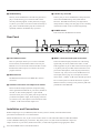
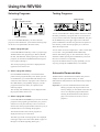
DIGITAL REVERBERATOR
Operation Manual
Manuel d’instructions
Bedienungsanleitung
Manual de Operación
M
FCC INFORMATION (U.S.A.)
1. IMPORTANT NOTICE: DO NOT MODIFY THIS UNIT!
This product, when installed as indicated in the instructions contained in this manual, meets FCC requirements. Modifications not expressly approved by
Yamaha may void your authority, granted by the FCC, to use the product.
2. IMPORTANT: When connecting this product to accessories and/or another product use only high quality shielded cables. Cable/s supplied with this product
MUST be used. Follow all installation instructions. Failure to follow instructions could void your FCC authorization to use this product in the USA.
3. NOTE: This product has been tested and found to comply with the requirements listed in FCC Regulations, Part 15 for Class "B" digital devices.
Compliance with these requirements provides a reasonable level of assurance that your use of this product in a residential environment will not result in
harmful interference with other electronic devices. This equipment generates/uses radio frequencies and, if not installed and used according to the
instructions found in the users manual, may cause interference harmful to the operation of other electronic devices. Compliance with FCC regulations does
not guarantee that interference will not occur in all installations. If this product is found to be the source of interference, which can be determined by turning
the unit "OFF" and "ON", please try to eliminate the problem by using one of the following measures:
Relocate either this product or the device that is being affected by the interference.
Utilize power outlets that are on different branch (circuit breaker of fuse) circuits or install AC line filter/s.
In the case of radio or TV interference, relocate/reorient the antenna. If the antenna lead-in is 300 ohm ribbon lead, change the lead-in to coaxial type cable.
If these corrective measures do not produce satisfactory results, please contact the local retailer authorized to distribute this type of product. If you can not
locate the appropriate retailer, please contact Yamaha Corporation of America, Electronic Service Division, 6600 Orangethorpe Ave, Buena Park, CA
90620
* This applies only to products distributed by YAMAHA CORPORATION OF AMERICA.
IMPORTANT NOTICE FOR
THE UNITED KINGDOM
Connecting the Plug and Cord
WARNING: THIS APPARATUS MUST BE EARTHED
IMPORTANT: The wires in this mains lead are coloured in accordance
with the following code:
ADVARSEL!
Lithiumbatteri–Eksplosionsfare ved fejlagtig håndtering.
Udskiftning må kun ske med batteri af samme fabrikat og type.
Levér det brugte batteri tilbage til leverandoren.
VARNING
GREEN-AND-YELLOW : EARTH
Explosionsfara vid felaktigt batteribyte. Använd samma batterityp
eller en ekvivalent typ som rekommenderas av apparattillverkaren.
Kassera använt batteri enligt fabrikantens instruktion.
BLUE
: NEUTRAL
VAROITUS
BROWN
: LIVE
Paristo voi räjähtää, jos se on virheellisesti asennettu. Vaihda
paristo ainoastaan laitevalmistajan suosittelemaan tyyppiin. Hävitä
käytetty paristo valmistajan ohjeiden mukaisesti.
As the colours of the wires in the mains lead of this apparatus may not
correspond with the coloured markings identifying the terminals in your
plug, proceed as follows:
The wire which is coloured GREEN-AND-YELLOW must be connected
to the terminal in the plug which is marked by the letter E or by the safety
earth symbol or coloured GREEN-AND-YELLOW.
The wire which is coloured BLUE must be connected to the terminal
which is marked with the letter N or coloured BLACK.
The wire which is coloured BROWN must be connected to the terminal
which is marked with the letter L or coloured RED.
* This applies only to products distributed by YAMAHA KEMBLE
MUSIC (U.K.) LTD.
NEDERLAND
THE NETHERLANDS
• Dit apparaat bevat een lithium batterij voor geheugen back-up.
• This apparatus contains a lithium battery for memory back-up.
• Raadpleeg uw leverancier over de verwijdering van de batterij op het
• For the removal of the battery at the moment of the disposal at the
moment dat u het apparaat ann het einde van de levensduur afdankt of
de volgende Yamaha Service Afdeiing:
end of the service life please consult your retailer or Yamaha Service
Center as follows:
Yamaha Music Nederland Service Afdeiing
Yamaha Music Nederland Service Center
Kanaalweg 18-G, 3526 KL UTRECHT
Tel. 030-2828425
Address: Kanaalweg 18-G, 3526 KL UTRECHT
Tel: 030-2828425
• Gooi de batterij niet weg, maar lever hem in als KCA.
• Do not throw away the battery. Instead, hand it in as small chemical
waste.
Precautions
1. Select a suitable location.
Keep the REV500 away from locations where it is
likely to be exposed to high temperatures or
humidity—such as near radiators, stoves, etc. Also
avoid locations which are subject to excessive dust
accumulation or vibrations that could cause
mechanical damage, and locations subject to strong
electromagnetic fields such as those produced by
broadcast equipment.
2. Avoid physical shocks.
Strong physical shocks can damage the REV500.
Handle the REV500 with care.
3. Do not open the case or attempt repairs or
modifications yourself.
This product contains no user-serviceable parts.
Refer all maintenance and repair work to qualified
Yamaha service personnel. Opening the case and/
or tampering with the internal circuitry voids the
warranty.
4. Always turn the power off before making
connections.
Always turn the power OFF before connecting or
disconnecting cables. Failure to do so may damage
the REV500 as well as other connected equipment.
5. Handle cables carefully.
Always grip the connector, not the cord itself, when
plugging and unplugging cables (including the AC
power cord).
6. Clean with a soft dry cloth.
Never use solvents such as benzine or thinner to
clean the REV500. Wipe the unit clean with a soft,
dry cloth.
7. Always use the correct power supply.
Make sure that the power requirements listed on the
rear panel of the REV500 match your local AC
mains
8. Have the back-up battery replaced regularly.
The REV500 has a long-life lithium battery that
maintains the contents of the user memory even
when the REV500 is off. Under normal use, the
battery should last several years. However, Yamaha
strongly recommends that you have the battery
replaced by a qualified Yamaha service center
every five years, to prevent the accidental loss of
valuable data.
Should the battery’s voltage fall below a certain
level, the message “LOW BATTERY” will appear in
the LCD when you turn the REV500 on. If this
happens, it means that contents of your REV500’s
user memory have been lost. Have the backup
battery replaced immediately.
Prompt and regular replacement of the back-up
battery is necessary to prevent the loss of important
data. In addition, if possible, you should use the
MIDI bulk dump function (see page 17) regularly to
store backup copies of your REV500’s data in a
MIDI sequencer other MIDI device. This will allow
you to recover your data should the back-up battery
run down sooner than you think.
Introduction
Congratulations on your purchase of a Yamaha REV500 Digital Reverberator! The REV500 is a high-quality,
inexpensive, and easy-to-use digital reverberator, suitable for home recording or smaller sound reinforcement
applications.
A true stereo processor with two inputs and two outputs, the REV500 offers high-quality stereo reverb, either
alone or in combination with a variety of other effects. The 20-bit A/D and D/A converters feature a 44.1 kHz
sampling rate, for superb sound quality and wide frequency response. The REV500 comes complete with 100
preset programs that take excellent advantage of this high-performance hardware, plus room for 100 more
programs that you can edit for yourself.
The REV500 is also flexible and simple to use. It lets you use either 1/4" phone or XLR connectors for both
input and output, and gives you the option of +4 dB input and output levels. Four rotary controls allow quick
and easy editing of the basic program parameters. And MIDI IN and OUT terminals allow remote program
selection, remote data storage, and realtime control of program parameters using MIDI messages.
To get the most out of your REV500 Digital Reverberator, please read this manual thoroughly and keep it on
hand for future reference.
Contents
Controls ........................................................... 1
System Functions ......................................... 14
Front Panel .................................................................... 1
Rear Panel ..................................................................... 2
Installation and Connections ........................................ 2
Selecting an Input Mode ............................................. 14
Selecting an Output Mode .......................................... 14
Setting the Footswitch Function ................................. 14
Adjusting the Audition Function ................................ 15
Changing the Initial Title Display .............................. 15
Initializing the REV500’s User Memory ................... 15
Using the REV500 ........................................... 3
Selecting Programs ....................................................... 3
Testing Programs .......................................................... 3
Automatic Demonstration ............................................ 3
REV500 Preset Program List ....................................... 4
Editing Programs ............................................ 8
Editing Basic Parameters .............................................. 8
Changing the Effect Level ............................................ 9
Realtime Parameter Control ......................................... 9
Editing Internal Parameters .......................................... 9
Changing a Program’s Title ......................................... 9
Internal Parameter List ............................................... 10
Saving Edited Programs ............................................. 13
Using MIDI Functions ...................................16
Selecting a MIDI Channel .......................................... 16
Using the MIDI OUT Function .................................. 16
Editing the MIDI Program Change Map .................... 16
Storing Data with MIDI Bulk Dumps ........................ 17
Appendix ........................................................ 18
Guide to Utility Mode Functions ............................... 18
Specifications.............................................................. 19
Dimensions ................................................................. 20
MIDI Data Format ............................................... Add-1
MIDI Implementation Chart ................................ Add-3
Program Data Sheet ............................................. Add-4
Controls
Front Panel
1
2
3
1 INPUT LEVEL control and meter
The INPUT LEVEL control sets the input level for both
the right and left input channels. It is accompanied by a
stereo LED meter that shows the levels of the signals
received by the REV500 after A/D conversion. Lighting
of the red CLIP LEDs thus indicates clipping of the
digital signal. You should adjust the control so that the
CLIP LEDs do not light.
2 PROGRAM keys
These keys let you choose the program that the REV500
will use to process the input sound.
The TYPE key selects the type of effect program to be
used: HALL, ROOM, PLATE, or SPECIAL. The current
program type selection is displayed in the upper left
corner of the LCD.
The PRESET/USER key selects between the PRESET
and USER program memory areas. The currently
selected memory area is displayed under the program
number in the LCD. It is possible to change the
parameters of a preset program, but the edited program
must be stored as a user program.
The NUMBER keys are used to select different programs
within the chosen program type and memory area. The
number and title of the currently selected program are
displayed in the top row of the LCD.
3 LCD
This LCD normally displays information about the
currently selected program. It also displays graphic
information about basic parameters being edited, as well
as a variety of other messages related to the REV500’s
utility functions.
4
56 789
4 PARAMETER EDIT controls
These controls let you edit the basic parameters of the
selected program.
The PRE DELAY control sets the amount of time that
will elapse before the onset of early reflections. It also
functions as a cursor control, which you can turn to
select the parameter or character to be modified when
using the REV500’s utility functions.
The REV TIME control sets the amount of time needed
for the reverberation to decay. It also functions as a data
entry control, which you can turn to change the values of
selected items when using the REV500’s utility
functions.
The HI-RATIO control sets the reverb time for the highfrequency components of the reverb, as a proportion of
the overall reverb time set using the REV TIME control.
The ER LEVEL control sets the level of the early
reflection component of the reverb. It is also used, in
combination with the EFF LEVEL key, to adjust the
overall effect output level.
5 EFF LEVEL key and LED
This key lets you use the ER LEVEL control to set the
overall effect output level. When the LED above this key
is lit, the ER LEVEL control will adjust the effect level
instead of the early reflection level.
6 STORE key
This key is used to store modified programs, and to
execute MIDI bulk dumps.
1
7 AUDITION key
8 UTILITY key and LED
This key causes the REV500’s internal tone generator to
play a sound, allowing you to check the effect of the
currently selected program. A utility function (see page
15) allows you to select one of two sounds for this key to
play, and to set the REV500 to play this sound once or
repeatedly when the AUDITION key is pressed.
This key lets you access the REV500’s utility functions,
which include MIDI settings and system-related
functions. The LED above this key will light when a
utility function is being used. See page 18 for a summary
of the functions that can be accessed using this key.
9 POWER switch
This switch turns the REV500 on and off.
Rear Panel
0
A
0 FOOT SW connector
This 1/4" phone jack allows you to connect a Yamaha
FC5 footswitch, for hands-free remote control of your
REV500. You can use the FC5 footswitch either to mute
the REV500’s effect output, or to advance the current
program selection.
A MIDI terminals
The REV500 sends and receives MIDI data via these
connectors.
B OUTPUT connectors and output level switch
B
C
C INPUT connectors and input level switch
These are balanced input jacks that receive the analog
signal from your mixer, multitrack recorder, or other
audio equipment. A pair of XLR connectors and a pair of
1/4" phone jacks are provided. If the sound source to be
processed is monophonic, insert the plug in the left (L)
connector only. Also, be sure to set the REV500 to use
mono input (refer to page 14). The input level switch
selects either –10 dB or +4 dB as the nominal input level.
Do not connect jacks to both the XLR and 1/4" phone
INPUT connectors, as doing so may adversely affect the
performance of the REV500.
These are balanced output jacks that output the analog
return signal from the REV500 to your mixer, multitrack
recorder, or other audio equipment. A pair of XLR
connectors and a pair of 1/4" phone jacks are provided. If
you desire monophonic output, insert the plug in the left
(L) connector only. The output level switch selects either
–10 dB or +4 dB as the nominal output level.
Installation and Connections
Before attempting to use your REV500, make sure that you have carefully read and understood the
precautions inside the front cover of this manual.
Mount the REV500 in a rack, or place it in a location where it is safe and stable. Make sure that the POWER
switch is off before making any connections. Plug in the power cord, and connect the REV500’s input and
output connectors to your mixer, multitrack recorder, or other audio equipment using appropriate cables.
Press the POWER switch to turn the REV500 on.
2
Using the REV500
Selecting Programs
Testing Programs
Program type
AUDITION key
Program number
Program title
Effect type
Program memory
You can use the PROGRAM keys to select a desired
program, as described below. (Note that the following steps
do not have to be performed in the order listed.)
1. Select a program type.
Use the PROGRAM TYPE key to select a program type.
The REV500 has four program types: HALL, ROOM,
PLATE, and SPECIAL. Each program type contains 25
programs, as described in the REV500 Preset Program
List on pages 4 through 7.
The current program type selection is displayed in the
upper left corner of the LCD.
2. Select a program memory.
Press the PRESET/USER key to switch between the
preset and user program memory areas. When you first
use the REV500, you will find that both memory areas
contain the same selection of programs. The contents of
the USER memory will gradually change as you edit
programs and store the results, as explained in the
following chapter.
The currently selected memory area is displayed under
the program number in the LCD.
3. Select a program number.
Use the PROGRAM NUMBER keys to choose one of the
programs in the program type and memory are you have
selected. You can press these keys once to increase or
decrease the current program number selection by one, or
hold them down to scan through the programs.
You can use the REV500’s handy audition function to check
the effect produced by a program when it’s inconvenient to
run your actual sound source through the REV500. Just press
the AUDITION key in the upper right corner of the front
panel. The REV500’s internal tone generator will produce a
tone that lets you hear how the program you’ve selected
affects the output sound.
You can select one of two sample tones—either a snare drum
or a rim shot—using the DEMO TONE TRIG utility
function described on page 15. This function also lets you
determine whether pressing the AUDITION key will cause
the tone to sound once or repeatedly.
If you set the audition function to play repeatedly, you can
stop it by pressing the AUDITION key a second time.
Automatic Demonstration
The REV500 has a demonstration mode that lets you hear
samples of some typical effect settings. To select
demonstration mode, hold down the UTILITY key and press
AUDITION.
Important: If you select the demonstration mode while
editing a program, the program will be reset
and any changes you have made will be lost. Be
sure to save important program data before
selecting the demonstration mode. (Refer to
page 13 for instructions on how to store a
program.)
The number and title of the current program are
displayed in the top row of the LCD.
The effect type of the current program is also displayed
in the upper right corner of the LCD. (Refer to pages 10
through 13 for details regarding effect types.)
3
REV500 Preset Program List
HALL
No.
1
2
Title
Large Hall 1
Large Hall 2
Effect Type*
REVERB
Description
Standard hall-type reverbs that simulate large halls with good acoustics. May be
used with any instrument. “Large Hall 1” is bright; “Large Hall 2” is slightly darker.
3
4
Empty Hall
Big Slap Hall
REVERB
REVERB
A reverb that simulates the feel of a large hall with no audience.
A bright reverb with breadth, thanks to slightly emphasized early reflec-
5
6
Arena
New Hall
REVERB
REVERB
tions.
A reverb with the low-range characteristics of an arena-sized concert space.
A bright reverb with a punch.
7
8
Wonder Hall
Dark Hall
REVERB
REVERB
A light, bright hall reverb. Good with percussion.
A rather dark hall reverb. Recommended for use with songs in minor keys.
9
10
11
Church 1
Church 2
Medium Hall 1
REVERB
REVERB
Reverbs that simulate the acoustics of high-vaulted cathedrals. “Church 1”
is dark; “Church 2” is brighter, with more reflections.
Standard medium-sized hall reverbs. “Medium Hall 1” is bright, with many
12
13
Medium Hall 2
Concert Hall
REVERB
reflections; “Medium Hall 2” is dark and dense.
A hall-type reverb with natural-sounding acoustics.
14
15
16
Small Hall 1
Small Hall 2
Gothic Hall
REVERB
REV+CHO
REVERB
Reverbs that simulate acoustically ideal small halls. “Small Hall 1” is
bright and live-sounding; “Small Hall 2” is somewhat darker.
A hall reverb with a growling chorus attack. Good for vocals and solo
instruments.
Longish hall reverbs for use with slow vocals. “Ballad Voc 1” is bright
17
Ballade Voc 1
18
19
Ballade Voc 2
Rev for Pads
REV➔FLG
and dense; “Ballad Voc 2” is dark and slightly less dense.
A long reverb with flanged high ranges, for a spacy sound. Good with padtype synths.
20
21
Ensemble Rev
Chorus Reverb
REV➔FLG
REV➔CHO
A short reverb with a warm flanger sound. Good for strings and organs.
A hall reverb with chorus added for extra thickness. Good with pianos and
22
Slapped Echo
ECHO➔REV
pad-type synths.
A reverb that captures the feel of an analog delay or tape echo. Good with
vocals or solos.
23
24
Flutter Hall
Kick Gate
REV➔GATE
REV➔GATE
A gated hall reverb with a long pre-delay.
A gated hall reverb, intended for use with bass drums.
25
Snare Gate
REV➔GATE
A gated hall reverb, intended for use with snare drums.
* Refer to pages 10 through 13 for details regarding effect types.
4
ROOM
No.
1
2
3
Title
Large Room 1
Large Room 2
Live Gate Room
Effect Type*
REVERB
Description
A reverb that simulates a large room with hard walls, for a slightly quirky
thick sound.
REVERB
REVERB
A large room reverb, slightly drier than “Large Room 1.”
A room reverb with a very live nonlinear sound. Good with drums and
4
5
Live Room 1
Live Room 2
REVERB
guitars.
Reverbs that simulate the sound of a room with live acoustics. Use “Live Room 1” to
simulate greater distance from the sound source, or “Live Room 2” for front-row seats.
6
7
Bath Room
Medium Room
REVERB
REVERB
A simulation of the reverb in a tile-walled bathroom.
A live-sounding reverb with the feel of a medium-sized recording studio.
8
9
Garage
Ring Studio
10
11
REV➔GATE
REVERB
A reverb that simulates the sound of a garage performance.
The nonlinear reverb sound of a small studio with emphatic high-range
acoustics.
Empty Store
Add to Dry Mix
REVERB
REVERB
A reverb simulating a room with nothing in it.
A room reverb that can add live sound to a dry two-channel mix source.
12
13
14
Heavy Bottom
Bright Room 1
Bright Room 2
REVERB
REVERB
REVERB
A room reverb with an emphasized low range, for a powerful sound.
A bright room reverb with extra early reflections.
A room reverb that sounds smaller, but more dense, than “Bright Room 1.”
15
16
Small Room
Tiny Gate Room
REVERB
REVERB
A standard small room simulation.
A somewhat dead nonlinear small room simulation.
17
18
19
Wood Room
Compact Room
Soft Space
REVERB
REV➔DFILT
REV+CHO
20
Room Ambience
21
22
23
Echo Vocal
Tunnel 1
Tunnel 2
24
25
Opera
Cathedral
REVERB
REVERB
REVERB
A small room simulation, dark and dead.
A very small room, simulated with short reverb and a dynamic filter.
A short reverb with chorus. Adds a soft ambiance to drums, solos, and
vocals.
Slightly coarse echo room simulations. Good for vocals and solo instruments.
Reverbs that simulate the acoustics inside a long tunnel. “Tunnel 2” is
darker than “Tunnel 1.”
Reverbs that simulate large rooms with marble walls. “Opera” is bright,
whereas “Cathedral” is dark.
* Refer to pages 10 through 13 for details regarding effect types.
5
PLATE
No.
1
2
Title
Basic Plate
Beauty Plate
Effect Type*
REVERB
REVERB
Description
A simulation of a metal plate echo effect.
A bright, highly dense plate reverb.
3
4
LA Plate
Delayed Spring
REVERB
REVERB
The bright, transparent plate sound that is popular on the West Coast.
A spring reverb simulation with a longish pre-delay.
5
Fat Plate
REVERB
6
Light Plate
REVERB
A rather coarse reverb with extra low-range energy. Good with vocals and
solos.
A bright, light plate sound.
7
8
Thin Plate
Rev with Tail
REVERB
REVERB
The plate echo that would be created by an extremely thin metal plate.
Complex reverb with a sub-reverb tail (when INPUT SELECT is set to L-
9
10
Short Plate
Perc. Plate 1
REVERB
REVERB
MONO).
A short, somewhat dark plate reverb.
A short, bright plate reverb for percussion. Adjust the pre-delay to match
11
Perc. Plate 2
REVERB
the tempo.
A short, light-sounding reverb. Perfect for cymbals.
12
13
14
Long Plate 1
Long Plate 2
Long Plate 3
REVERB
Three longish plate reverbs, each of which features different high-range
characteristics.
15
Vocal Plate 1
REVERB
A plate reverb for use with vocals. Designed for ballads and other slow
songs.
16
17
18
Vocal Plate 2
Vocalese
Live Plate
REVERB
REV+CHO
ECHO➔REV
A slightly darker-sounding reverb than “Vocal Plate 1.”
A slightly chorused reverb. Good with guitars and keyboards.
An echo/reverb combination for vocals and solo instruments during live
REVERB
performances.
A short plate reverb with a chopped low range. Good with analog rhythm
19
Industrial Rev
20
21
Strings Space
Cave
REVERB
22
Super Long
REVERB
23
24
25
Mod Plate
Water Reverb
Gate Plate
REV➔SYM
REV➔FLG
REV➔GATE
machines, etc.
Plate reverbs with very long reverb times. “String Space” is bright with a broad bandwidth, whereas “Cave” is dark with heavy low-range components. Good for pad synths.
A plate reverb with a very long tail (when INPUT SELECT is set to LMONO).
A reverb with symphonic effect. Good for guitars and keyboards.
A slightly flanged long reverb. Beautiful used with guitar arpeggios, etc.
A plate reverb with a gate envelope. Good with snare drums and such.
* Refer to pages 10 through 13 for details regarding effect types.
6
SPECIAL
No.
1
2
Title
Flange Room
Reverb Chorus
Effect Type*
REV➔FLG
REV+CHO
Description
A short reverb combined with a flanger. Good with organs, strings, etc.
Short reverbs combined with chorus. The longer pre-delay of “Chorus Circles”
3
4
Chorus Circles
Rez Sweep Hall
REV➔RESO
emphasizes the sense of separation between the reverb and chorus effects.
A flanger-like effect with a resonance point that varies with the input level.
5
6
7
Shadow Reverb
Sweep Reverb
Rev Flange 1
REV➔RESO
A reverb with the resonance point set at E.
8
9
Rev Flange 2
Heavy Flange
more pronounced as the program number increases.
10
11
12
Pan Reverb
Rev Tremolo
Skinny Plate
Five combinations of reverb and tremolo. The tremolo becomes faster as
the program number increases. “Shake Shake” and “Sample & Hold” use
square wave modulation for a pronounced tremolo effect. Adjust the
13
14
Shake Shake
Sample & Hold
15
Pan Feedback
ECHO➔REV
16
Long Echo
ECHO➔REV
17
18
Dyna Filter 1
Dyna Filter 2
REV➔DFIL
Effects that change the sound depending on the input level; turns acoustic
drums into synth drums. “Dyna Filter 1” has a long decay; “Dyna Filter 2”
19
20
21
Dyna Filter 3
Backward
Industry
REV➔RESO
REV➔CHO
REVERB
has a short decay. “Dyna Filter 3” uses the resonator, for a different effect.
An attempt at a reverse gate effect. Good with drums and guitars.
A special effect that uses the maximum pre-delay and early reflection
REV➔FLG
REV➔TRM
Four variations on the reverb/flanger theme. The flanger effect becomes
tremolo speed to suit the song.
An echo with more feedback further away from stereo center. (Use with
INPUT SELECT set to STEREO.)
An effect that combines a repeat delay with a short reverb.
settings.
22
Natural Gate
23
24
25
Drum Fizz Gate
Techno Gate
Gate for Loop
REV➔GATE
Four gated reverb variations. Change the hold time and gate level as
needed for the best effect.
* Refer to pages 10 through 13 for details regarding effect types.
7
Editing Programs
REV TIME
Editing Basic Parameters
This control sets the length of the main reverberation.
Possible reverb time values range from 0.3 to 99 seconds.
REVERB
ER LEVEL
Early
Reflections
Time
PRE
DELAY
E/R DLY
REV TIME
HI-RATIO
Reverb Time x
This control sets the reverb time for the high-frequency
component of the reverb effect as a proportion of the overall
reverb length (REV TIME parameter). Possible values are
0.1 to 1.0.
LO-RATIO
1.0
HI-RATIO
Frequency
The four PARAMETER EDIT controls on the REV500’s
front panel let you adjust the basic program parameters
quickly and easily. When you rotate one of these controls,
the program information in the LCD (shown above) will be
replaced by a graphic display indicating how the changes
you’ve made have affected the parameter in question. (The
display will return to normal a few moments after you stop
turning the control.)
Please note that you must save any changes you make before
you select another program or turn off the REV500; if you
fail to do so, your edited program will be lost. Refer to page
13 for instructions on how to store a program.
PRE DELAY
This control sets the length of the initial delay that will pass
before the reverb effect (including early reflections) begins.
You can set a delay from 0.0 ms to 200.0 ms (or 299.9 ms if
the ECHO➔REV effect type is selected).
8
ER LEVEL
This control sets the level of the early reflections (i.e., the
initial reflections that precede the main reverberation). You
can set early reflection levels ranging from 0 to 100.
Changing the Effect Level
You can also use the ER LEVEL control to adjust the effect
level, that is, the level of the total effect output. To do so,
press the EFF LEVEL key before turning the ER LEVEL
control. The LED above this key will light, and (as with the
other basic parameters) the program information in the LCD
will be replaced by a graphic display. You can set a level
from 0 to 100.
Use the PRE DELAY control to move the cursor from the
parameter name to the parameter value and vice-versa. Use
the REV TIME control to select the parameter you wish to
edit, and to adjust the value assigned to the parameter you
select.
Please note that the parameters available for editing will vary
with the effect type of the program you have selected. You
can identify the effect type of a program by checking the
upper right corner of the LCD.
Effect type
Refer to the next section for a list of the internal parameters
for each effect type.
Realtime Parameter Control
The REV500 also lets you dynamically change the
aforementioned basic parameters in realtime, using MIDI
Control Change messages. The controller numbers for these
parameters are shown in the table below.
MIDI Controller Numbers
Parameter
Ctrl. No.
PRE DELAY
12
REV TIME
13
HI-RATIO
14
ER LEVEL
15
EFF LEVEL
16
Editing Internal Parameters
In addition to the basic parameters described previously, the
REV500’s programs have a variety of internal parameters
that can also be edited.
To edit a program’s internal parameters, press the UTILITY
key. If necessary, press the UTILITY key again until the
INT. PARAMETER display appears:
Cursor Value
Parameter name
When you are done editing internal parameters, press one of
the PROGRAM keys to exit the utility mode. Remember that
(as with other program parameters) you must save the
program you have just edited before selecting another
program or turning the REV500 off, or your changes will be
lost. Refer to page 13 for instructions on how to store a
program.
Changing a Program’s Title
You can assign a program you have edited a new title, for
easy recognition.
To edit a program’s title, begin by pressing the UTILITY
key. The LED above this key will light, and one of the
REV500’s utility function displays will appear in the LCD.
If necessary, press the UTILITY key again until the TITLE
EDIT display appears:
Cursor
Use the PRE DELAY control to select a character you wish
to change, and the REV TIME control to change that
character. Repeat this process until the title appears as you
wish it to read.
When you are done editing the title, press one of the
PROGRAM keys to exit the utility mode. Remember that (as
with other program parameters) you must save the program
you have just edited before selecting another program or
turning the REV500 off, or your new title will be lost. Refer
to page 13 for instructions on how to store a program.
9
Internal Parameter List
This section contains lists of the internal parameters for each effect type, together with a block diagram
illustrating how the effect works. Since it is also possible to control internal parameters in realtime using
MIDI Control Change messages, the corresponding controller numbers are also included in the lists.
COMMON
The internal parameters in the following table are common to all effect types.
Parameter
Ctrl. No.
Range
Description
LO-RATIO
17
0.1 — 2.4
Low frequency reverb time, proportional to REV TIME
DIFFUS
18
0 — 10
Spread of reverb sound
HPF
19
THRU, 20 — 1.0k [Hz]
Cutoff frequency of high pass filter
LPF
20
THRU, 500 — 20k [Hz]
Cutoff frequency of low pass filter
REVERB
The parameters in the following table are available for simple reverb effects.
Parameter
Ctrl. No.
Range
Description
DENSITY
21
0 — 100 [%]
Density of reverberation
LIVENESS
22
0 — 10
Early reflection decay characteristics (0 = dead, 10 = live)
E/R DLY
23
0.0 — 100.0 [ms]
Delay from start of early reflections to start of reverb
Input Signal Envelope
REVERB ➔ GATE
In this effect type, the output from the reverb is fed into a gate.
GATE LVL
Time
Gate Envelope
Time
HOLD DECAY
10
Parameter
Ctrl. No.
Range
Description
GATE LVL
24
-60 — 0 [dB]
Gate threshold level
HOLD
25
1 — 5759 [ms]
Time from hold time that the gate remains open
DECAY
26
1 — 24000 [ms]
Time needed for gate to close completely
DETECT
27
PRE, POST
Point at which threshold level is detected
REVERB ➔ RESONATOR
In this effect type, the output from the reverb is fed into a resonator.
Parameter
Ctrl. No.
Range
Description
SENS
28
1 — 10
Sensitivity of the resonator input signal
RESO
29
0 — 100 [%]
Resonator feedback level
DECAY
30
6 — 24000 [ms]
Speed of resonance point return to lowest frequency
MIX
31
0 — 100 [%]
Balance of reverb direct output and resonator output
REVERB ➔ DYNAMIC FILTER
In this effect type, the output from the reverb is fed into a dynamic filter.
Depend on SENS, DECAY and
input signal envelope.
RESO
Frequency
OFFSET
Parameter
Ctrl. No.
Range
Description
SENS
70
0 — 10
Low frequency reverb time, proportional to REV TIME
OFFSET
71
0 — 64
Offset from the minimum of the cutoff frequency
RESO
72
0 — 20
Degree of filter resonance
DECAY
73
6 — 24000 [ms]
Speed of cutoff level return to minimum
11
REVERB + CHORUS
This effect type, the source sound is processed separately by both the reverb and a chorus effect. The results
of this parallel processing are then mixed for output.
Note that in this effect type, the LPF and HPF (see COMMON parameters, above) are applied immediately
before the PRE DELAY. Hence, these filters do not affect the sound processed by the chorus effect.
Parameter
Ctrl. No.
Range
Description
SPEED
74
0.05 — 10.00 [Hz]
Modulation frequency
DEPTH
75
0 — 100 [%]
Modulation depth
MIX
77
0 — 100 [%]
Cutoff frequency of low pass filter
REVERB ➔ CHORUS, FLANGER or SYMPHONIC
In these effect types, the output from the reverb is fed into a chorus, flanger, or symphonic effect.
Parameter
12
Ctrl. No.
Range
Description
SPEED
74
0.05 — 10.00 [Hz]
Modulation frequency
DEPTH
75
0 — 100 [%]
Modulation depth
FB LVL
76
0 — 100 [%]
Feedback level (REVERB ➔ FLANGER effects only)
MIX
77
0 — 100 [%]
Cutoff frequency of low pass filter
REVERB ➔ TREMOLO
In this effect type, the output from the reverb is fed into a tremolo effect.
Parameter
Ctrl. No.
Range
Description
SPEED
78
0.05 — 10.0 [Hz]
Modulation frequency
DEPTH
79
0 — 100 [%]
Modulation depth
PHASE
80
0 — 354.4 [°]
Phase difference between right and left channels
WAVE
81
SINE, TRI, SQR
Waveform used by low frequency oscillator
ECHO ➔ REVERB
In this effect type, the output of the reverb’s PRE DELAY block is fed back into the reverb input to produce
an echo effect.
Parameter
Ctrl. No.
Range
Description
FB LVL
82
-100 — +100 [%]
Level of feedback to own channel
CROSS FB
83
-100 — +100 [%]
Level of feedback to opposite channel
Saving Edited Programs
You must save the programs you have edited before
selecting a different program or turning off the REV500, or
the changes you make will be lost.
To save a program, press the STORE key. The program
number in the LCD will begin to flash, and the REV500 will
ask you if it’s okay to store the program. (If you are editing a
preset program, the memory area indicator under the
program number will automatically change to USER.)
If you want to save your program under a different program
number, use the PROGRAM NUMBER keys to change the
program number. (You cannot change the program type,
however.) Press STORE a second time when you are sure
you’re ready to save the program, and the REV500 will
comply.
If you decide you’d rather not store the program after all,
simply press the PROGRAM TYPE key or the PRESET/
USER key, and the display will return to normal.
13
System Functions
Selecting an Input Mode
Setting the Footswitch Function
If you will be using the REV500 to process monophonic
input (from the left input connector), you must use the
INPUT SELECT function to inform it of this fact.
You can use an FC5 footswitch with your REV500, for
hands-free control of one of two functions frequently
required during live performances. You can use the
footswitch either to mute the REV500’s effect output, or to
advance the current program selection.
To change the input mode, first press the UTILITY key. If
necessary, press the UTILITY key again until the INPUT
SELECT display appears:
Stereo input
Mono input
Use the REV TIME control to switch between the STEREO
and L-MONO input settings. When you have made your
setting, press one of the PROGRAM keys to exit the utility
mode.
Selecting an Output Mode
You can set the REV500 to output the processed effect
signal only, or a mixture of the both direct output and the
processed signal. (If you elect to add the direct signal, the
balance between the direct and effect output signals will be
determined by the EFF LEVEL setting.)
To change the output mode, first press the UTILITY key. If
necessary, press the UTILITY key again until the OUTPUT
MODE display appears:
Effect output only
Effect plus direct output
Use the REV TIME control to switch between the EFFECT
ONLY and ADD DIRECT output mode settings. When you
have made your setting, press one of the PROGRAM keys to
exit the utility mode.
14
You can select which of these two roles the footswitch will
perform using a utility function. To access this function,
press the UTILITY key. The LED above this key will light,
and one of the REV500’s utility function displays will
appear in the LCD. If necessary, press the UTILITY key
again until the FOOT SWITCH display appears:
Footswitch mutes effect
Footswitch
changes program
Program
change range
Use the REV TIME control to switch between the EFF
MUTE and PGM SEL functions. If you select the former, the
REV500’s effect output will be suppressed when you
depress the footswitch. Depress the footswitch again to
release the effect mute.
If you select the latter function, depressing the footswitch
will cause the current program selection to advance in the
order specified by the MIDI program change map (see page
16). This function also lets you adjust the range of MIDI
program change numbers that the footswitch can select. Use
the PRE DELAY control to move the cursor from PGM SEL
to the range setting, then use the REV TIME control to
adjust the upper value of this setting (which may be
anywhere from 1 to 128). The footswitch will advance the
current program selection until it reaches the program
change number you have set. Depressing the footswitch
again will return the program change number to 1.
When you have made your settings, press one of the
PROGRAM keys to exit the utility mode.
Adjusting the Audition Function
Changing the Initial Title Display
The REV500 lets you customize the audition function to suit
your needs. You can select one of two tones: either a snare
drum or a rim shot. You can also specify whether pressing
the AUDITION key will play the selected tone once, or start
it playing repeatedly. You can also turn the function off, to
prevent the REV500 from producing unwanted sounds if this
key is pressed accidentally.
This utility function lets you personalize your REV500 by
entering a short message that will be displayed briefly when
you turn on the power. This message can consist of two lines
of up to 14 characters each.
To edit this initial title display, begin by pressing the
UTILITY key. If necessary, press the UTILITY key again
until the INI TITLE 1/2 display appears:
To adjust the audition function, first press the UTILITY key.
If necessary, press the UTILITY key again until the DEMO
TONE TRIG display appears:
Cursor
Tone selection
Trigger mode
Cursor
Use the PRE DELAY control to move the cursor from the
tone selection parameter to the trigger mode parameter, and
vice-versa. Use the REV TIME control to select the desired
tone (SNARE or RIM), or the desired trigger mode (OFF,
ONCE, or SEQ).
When you are satisfied with your settings, press one of the
PROGRAM keys to exit the utility mode.
Cursor
This display is used to edit the first line of the initial title.
Use the PRE DELAY control to select a character you wish
to change, and the REV TIME control to change that
character. Repeat this process until the line appears as you
wish it to read.
When you are satisfied with this line of your startup
message, press the UTILITY key a second time to display
the INI TITLE 2/2 display. Repeat the process to edit the
second line.
When you are done editing the initial title, press one of the
PROGRAM keys to exit the utility mode.
Initializing the REV500’s User
Memory
At some point you may wish to clear the edited programs out
of your REV500’s user memory and restore it to factory
condition. The method for doing this is as follows:
Hold the STORE key down as you turn the POWER switch
on. The REV500 will instruct you to press the STORE key a
second time to initialize its memory. Press the STORE key
to go ahead with the initialization, or any other key if you
decide you don’t want to.
Please be aware that this procedure will initialize any system
settings and MIDI settings (such as the MIDI program
change map) as well as the contents of the user memory area.
15
Using MIDI Functions
Selecting a MIDI Channel
You can change the MIDI channel that the REV500 uses to
transmit and receive data. First, press the UTILITY key. If
necessary, press the UTILITY key again until the MIDI
CHANNEL display appears:
MIDI channel setting
Use the REV TIME control to select the desired MIDI
channel. You can set the REV500 to use any of channels 1
through 16, or select OMNI for all channels. You can also
select OFF to disable MIDI communication.
When you have made your setting, press one of the
PROGRAM keys to exit the utility mode.
Using the MIDI OUT Function
This function determines whether MIDI channel messages
received at the MIDI IN terminal will be echoed through to
the MIDI OUT terminal. You should turn this function on
when you want to connect two or more REV500s in a “daisy
chain” so they can be controlled by a single master device
such as a sequencer or keyboard.
Begin by pressing the UTILITY key. If necessary, press the
UTILITY key again until the MIDI OUT display appears:
MIDI message echo setting
Use the REV TIME control to select between the ECHO
BACK ON and ECHO BACK OFF settings. If you choose
ECHO BACK ON, the MIDI channel messages received at
the MIDI IN terminal will be echoed through to the MIDI
OUT terminal. (Other messages received at the MIDI IN
terminal will not be echoed.)
When you have made your setting, press one of the
PROGRAM keys to exit the utility mode.
16
Editing the MIDI Program Change
Map
The REV500 has a MIDI program change map that assigns
REV500 programs to MIDI program change numbers. This
feature facilitates remote selection of REV500 programs
(which are stored in eight banks numbered 1 through 25)
using MIDI Program Change messages (which can specify
program numbers from 1 through 128).
To edit the MIDI program change map, first press the
UTILITY key. If necessary, press the UTILITY key again
until the MIDI PGM TABLE display appears:
REV500 program selection
MIDI program change
number and cursor
Use the PRE DELAY control to move the cursor to the MIDI
program change number, and the REV TIME control select a
program change number whose program assignment you
want to change. Then move the cursor back to the REV500
program selection, and use the REV control again to select
the program that you want the REV500 to use when it
receives the selected program change number.
Repeat this process to change as many MIDI program
change assignments as you like. When you are done editing
the program change map, press one of the PROGRAM keys
to exit the utility mode.
If you are using a Yamaha FC5 footswitch with the
REV500’s footswitch utility function set to PGM INC/DEC,
depressing the footswitch will select REV500 programs
sequentially in the order specified by this MIDI program
change map.
Storing Data with MIDI Bulk Dumps
The REV500 is capable of transmitting its data as bulk
dumps, for storage in a sequencer or other MIDI device. To
use this function, first make sure that the REV500 is
properly connected to the device that is to receive the data,
and that the MIDI channels of the two devices match.
Next, press UTILITY. If necessary, press the UTILITY key
again until the MIDI BULK DUMP display appears:
Bulk dump type
Program selection
Use the REV TIME control to select the type of bulk dump
to be transmitted. The REV500 is capable of sending four
types of bulk data:
MIDI Bulk Dumps
Dump Type
Data transmitted
ALL
All data (system setup data, all user
programs, and program table data)
SYSTEM
All system setup data
PGM
Data for all programs, or data for a
single specified program
PGM TABLE
MIDI program table data
If you select PGM as the bulk dump type, you must select
the program to be dumped. Use the PRE DELAY control to
move the cursor to the program selection, and the REV
TIME control to change the setting. If you select ALL PGM,
the REV500 will send the data for all user programs as a
single dump. You may also select a single user program and
store it externally using an individual data dump.
When you are satisfied with your selection, press the STORE
key. The REV500 will execute the data dump.
When you are finished transmitting data, press one of the
PROGRAM keys to exit the utility mode.
17
Appendix
Guide to Utility Mode Functions
The following table briefly describes the functions that can be accessed using the UTILITY key. Each
function is listed in order of appearance. The number to the right of the function’s descrption indicates the
page of this manual where you will find instructions on use of the function.
Utitlity Mode Functions
Function
Type
Description
INT. PARAMETER
Program edit
Used to edit the internal parameters of the
TITLE EDIT
INPUT SELECT
OUTPUT MODE
FOOT SWITCH
MIDI CHANNEL
MIDI THRU
MIDI PGM TABLE
MIDI BULK DUMP
DEMO TONE TRIG
INI TITLE 1/2
INI TITLE 2/2
18
Program edit
System setting
System setting
System setting
System setting (MIDI)
System setting (MIDI)
System setting (MIDI)
MIDI utility
System setting
System setting
System setting
Page
currently selected program.
9
Allows editing of the title of the currently
selected program.
9
Sets the REV500 to use either mono or stereo
input
14
Switches between efffect output only and
effect output plus direct source output
14
Selects the REV500 function that can be
controlled by a connected footswitch
14
Sets the MIDI channel that the REV500 will
use to receive and send MIDI data
16
Sets whether the MIDI OUT terminal will act
as a MIDI OUT or merged MIDI THRU
16
Assigns REV500 programs to MIDI Program
Change numbers
16
Transmits REV500 program or system setting
data to another MIDI device
17
Sets the tone and trigger mode for the
REV500’s audition function.
15
Allows editing of the first line of the initial
title message displayed at startup
15
Allows editing of the second line of the initial
title message displayed at startup
15
Specifications
ELECTRICAL CHARACTERISTICS
Frequency Reponse
20 Hz to 20 kHz
(+1.0 dB, -2.0 dB)
Dynamic Range
96 dB typical
Distortion
Less than 0.03% (1 kHz,
max level)
FRONT PANEL
Switches
PROGRAM TYPE,
PRESET/USER,
PROGRAM NUMBER –,
PROGRAM NUMBER +,
EFF LEVEL, STORE,
AUDITION, UTILITY,
POWER
Rotary Controls
INPUT LEVEL,
PRE DELAY, REV TIME,
HI-RATIO, ER LEVEL
Display
Stereo input level LED (–24,
–12, –6, CLIP), LCD,
EFF LEVEL LED,
UTILITY LED
INPUT
Number of Channels
2 (phone or XLR jack)
Nominal Level
+4 or –10 dB (selected by
rear panel switch)
Impedance
20 kΩ
OUTPUT
Number of Channels
2 (phone or XLR jack)
Nominal Level
+4 or –10 dB (selected by
rear panel switch)
Impedance
REAR PANEL
Connectors
INPUT L/R (1/4" phone),
INPUT L/R (XLR),
FOOT SW (1/4" phone),
OUTPUT L/R (1/4" phone),
OUTPUT L/R (XLR),
MIDI IN, MIDI OUT
Switches
Input level selector,
output level selector
150 Ω
AD/DA CONVERSION
AD Conversion
20 bit (64X oversampling)
DA Conversion
20 bit (8X oversampling)
Sampling Frequency
44.1 kHz
POWER REQUIREMENTS
PROGRAM MEMORY
Memory areas
Memory configuration
PRESET (read-only),
USER (read/write)
Four program types (HALL,
ROOM, PLATE, SPECIAL)
with 25 programs per type.
USA and Canada
120V AC, 60 Hz
General
230V AC, 50 Hz
POWER CONSUMPTION
15W
PHYSICAL
Dimensions (W x H x D)
480 mm x 45 mm x 227.9
mm
Weight
3.5 kg
OPTION
Footswitch FC5
19
388
W: 480
20
44
H: 45
28.1
15.9
2.6
151.5
203
D: 227.9
26
6.4
440
1
Dimensions
1. Transmitted data
1-1. System information
#1 Program bulk data
status
1111 0000(F0H)
ID No.
0100 0011(43H)
sub status 0000 nnnn(0nH)
format no. 0111 1110(7EH)
byte count 0000 0000(00H)
byte count 0100 1000(48H)
0100 1100(4CH)
0100 1101(4DH)
0010 0000(20H)
0010 0000(20H)
0011 1000(38H)
0100 0001(41H)
0011 1001(39H)
0011 1001(39H)
data name 0100 1101(4DH)
program no. 0mmm mmmm
data
0000 dddd
System exclusive
YAMAHA
n = 0 - 15
“L”
“M”
Space
Space
“8”
“A”
“9”
“9”
“M”
m = 1 - 100
Memory bulk
(62 bytes)
:
:
0000 dddd
check sum 0eee eeee
EOX
1111 0111(F7H) End of exclusive
#2 Program Change Table bulk data
status
1111 0000(F0H) System exclusive
ID No.
0100 0011(43H) YAMAHA
sub status 0000 nnnn(0nH) n = 0 - 15
format no. 0111 1110(7EH)
byte count 0000 0010(02H)
byte count 0000 1010(0AH)
0100 1100(4CH) “L”
0100 1101(4DH) “M”
0010 0000(20H) Space
0010 0000(20H) Space
0011 1000(38H) “8”
0100 0001(41H) “A”
0011 1001(39H) “9”
0011 1001(39H) “9”
data name 0101 0100(54H) “T”
bank no. 0000 0001(01H)
data
0000 dddd
Program change
data (256 bytes)
:
:
0000 dddd
check sum 0eee eeee
EOX
1111 0111(F7H) End of exclusive
#3 System Setup bulk data
status
1111 0000(F0H) System exclusive
ID No.
0100 0011(43H) YAMAHA
sub status 0000 nnnn(0nH) n = 0 - 15
format no. 0111 1110(7EH)
byte count 0000 0000(00H)
byte count 0100 1100(4CH)
0100 1100(4CH) “L”
0100 1101(4DH) “M”
0010 0000(20H) Space
0010 0000(20H) Space
0011 1000(38H) “8”
0100 0001(41H) “A”
0011 1001(39H) “9”
0011 1001(39H) “9”
data name 0101 0011(53H) “S”
0010 0000(20H) Space
data
0000 dddd
System setup
memory (66 bytes)
:
:
0000 dddd
check sum 0eee eeee
EOX
1111 0111(F7H) End of exclusive
#4 Parameter Change data
status
1111 0000(F0H) System exclusive
ID No.
0100 0011(43H) YAMAHA
sub status 0001 nnnn(1nH) n = 0 - 15
format no. 0001 1110(1EH)
device code 0000 0110(06H) REV500
parameter no. 0000 pppp
*1)
0000 pppp
data
0000 dddd
parameter data (4
bytes)
0000 dddd
0000 dddd
0000 dddd
EOX
1111 0111(F7H) End of exclusive
#5 Current buffer bulk data
status
1111 0000(F0H) System exclusive
ID No.
0100 0011(43H) YAMAHA
sub status 0000 nnnn(0nH) n = 0 - 15
format no. 0111 1110(7EH)
byte count 0000 0000(00H)
byte count 0100 1000(48H)
0100 1100(4CH) “L”
0100 1101(4DH) “M”
0010 0000(20H) Space
0010 0000(20H) Space
0011 1000(38H) “8”
0100 0001(41H) “A”
0011 1001(39H) “9”
0011 1001(39H) “9”
data name 0100 1101(4DH) “M”
program no. 0000 0000(00H)
data
0000 dddd
Memory bulk
(62 bytes)
:
:
0000 dddd
check sum 0eee eeee
EOX
1111 0111(F7H) End of exclusive
2. Receive data
2-1. Channel information
#1 Program Change
status
1100 nnnn(CnH) n = 0 - 15
program no. 0ppp pppp
p = 0 - 127
#2 Control Change
status
1011 nnnn(BnH) n = 0 - 15
controller no. 0ccc cccc
*2)
control value 0vvv vvvv
v = 0 - 127
Additions
MIDI data format
2-2. System information
#1 Program bulk dump request
status
1111 0000(F0H) System exclusive
ID No.
0100 0011(43H) YAMAHA
sub status 0010 nnnn(2nH) n = 0 - 15
format no. 0111 1110(7EH)
0100 1100(4CH) “L”
0100 1101(4DH) “M”
0010 0000(20H) Space
0010 0000(20H) Space
0011 1000(38H) “8”
0100 0001(41H) “A”
0011 1001(39H) “9”
0011 1001(39H) “9”
data name 0100 1101(4DH) “M”
program no. 0mmm mmmm m = 1 - 100
EOX
1111 0111(F7H) End of exclusive
Add-1
#2
Program Change Table bulk dump
request
status
1111 0000(F0H) System exclusive
ID No.
0100 0011(43H) YAMAHA
sub status 0010 nnnn(2nH) n = 0 - 15
format no. 0111 1110(7EH)
0100 1100(4CH) “L”
0100 1101(4DH) “M”
0010 0000(20H) Space
0010 0000(20H) Space
0011 1000(38H) “8”
0100 0001(41H) “A”
0011 1001(39H) “9”
0011 1001(39H) “9”
data name 0101 0100(54H) “T”
bank no. 0000 0001(01H)
EOX
1111 0111(F7H) End of exclusive
#3 System Setup bulk dump request
status
1111 0000(F0H) System exclusive
ID No.
0100 0011(43H) YAMAHA
sub status 0010 nnnn(2nH) n = 0 - 15
format no. 0111 1110(7EH)
0100 1100(4CH) “L”
0100 1101(4DH) “M”
0010 0000(20H) Space
0010 0000(20H) Space
0011 1000(38H) “8”
0100 0001(41H) “A”
0011 1001(39H) “9”
0011 1001(39H) “9”
data name 0101 0011(53H) “S”
0010 0000(20H) Space
EOX
1111 0111(F7H) End of exclusive
#4 Parameter Value Request
status
1111 0000(F0H) System exclusive
ID No.
0100 0011(43H) YAMAHA
sub status 0011 nnnn(3nH) n = 0 - 15
format no. 0001 1110(1EH)
device code 0000 0110(06H) REV500
parameter no. 0000 pppp
*1)
0000 pppp
EOX
1111 0111(F7H) End of exclusive
#5 Current buffer bulk dump request
status
1111 0000(F0H) System exclusive
ID No.
0100 0011(43H) YAMAHA
sub status 0010 nnnn(2nH) n = 0 - 15
format no. 0111 1110(7EH)
0100 1100(4CH) “L”
0100 1101(4DH) “M”
0010 0000(20H) Space
0010 0000(20H) Space
0011 1000(38H) “8”
0100 0001(41H) “A”
0011 1001(39H) “9”
0011 1001(39H) “9”
data name 0100 1101(4DH) “M”
program no. 0000 0000(00H)
EOX
1111 0111(F7H) End of exclusive
*1) Ask Yamaha service representative
*2) Correspondence of controller numbers
to parameters
EFFECT
PARAMETER
ALL
PRE DELAY
REV TIME
HI-RATIO
ER LEVEL
EFF LEVEL
LO-RATIO
DIFFUS
HPF
LPF
12
13
14
15
16
17
18
19
20
REV
DENSITY
LIVENESS
E/R DLY
21
22
23
REV➔GATE
#7 Program Change Table bulk data
The transmitted data is identical to “Program
Change Table bulk data.”
GATE LVL
HOLD
DECAY
DETECT
24
25
26
27
REV➔RESO
SENS
RESO
DECAY
MIX
28
29
30
31
#8 System Setup bulk data
The transmitted data is identical to “System
Setup bulk data.”
REV➔DFILT
SENS
OFFSET
RESO
DECAY
70
71
72
73
REV+CHO
REV➔CHO
REV➔FLG
REV➔SYM
SPEED
DEPTH
FB LVL*
MIX
74
75
76
77
REV➔TRM
SPEED
DEPTH
PHASE
WAVE
78
79
80
81
ECHO➔REV
FB LVL
CROSS FB
82
83
#6 Program bulk dump
The transmitted data is identical to “Program
bulk data.”
#9 Parameter Change data
The transmitted data is identical to “Parameter
Change data.”
* REV➔FLG only
Add-2
Ctrl. No.
YAMAHA [Digital Reverberator]
Model: REV500 MIDI Implementation Chart
Function...
Date: 8/26, 1996
Version: 1.0
Transmitted
Recognized
Remarks
Basic
Channel
Default
Changed
x
x
1-16, off
1-16, off
Memorized
Default
Messages
Altered
x
x
* ** *** ** ** *** *
OMNI off/ OMNI off
x
x
Memorized
Mode
: True voice
x
* ** *** ** ** *** *
x
x
Velocity
Note ON
Note OFF
x
x
x
x
After
Touch
Key's
Ch's
x
x
x
x
x
x
12 -31
70 - 83
x
x
o
o
*1
x
* ** *** ** ** *** *
o
*2
: True #
System Exclusive
o
o
Bulk Dump
System
: Song Pos
: Song Sel
Common : Tune
x
x
x
x
x
x
System : Clock
Real Time : Commands
x
x
x
x
: Local ON/OFF
Aux
: All Notes OFF
Messages : Active Sense
: Reset
x
x
x
x
x
x
x
x
Note
Number
Pitch Bender
Control
Prog
Change
Notes :
Additions
Change
*1 = Depend on effect type.
*2 = For program 1 - 128, REV500 program is selected.
Mode 1: OMNI ON, POLY
Mode 3: OMNI OFF, POLY
Mode 2: OMNI ON, MONO
Mode 4: OMNI OFF, MONO
o : Yes
x : No
Add-3
Add-4
98 07 10000 AP Printed in Japan
VV15160 R3 1 AP 100
Pro Audio Division, #18/3
P.O. Box 3, Hamamatsu, 430-8651, Japan
25
24
23
22
21
20
19
18
17
16
15
14
13
12
11
10
9
8
7
6
5
4
3
2
1
No.
Program Name
Program Type:
Effect Type
PRE DELAY REV TIME HI-RATIO ER LEVEL EFF LEVEL LO-RATIO
DIFFUS
Program Data Sheet
HPF
LPF
Internal Parameters peculiar to Effect Type