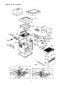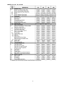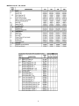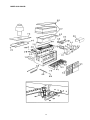
1
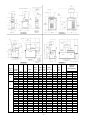
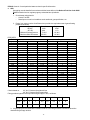
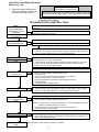
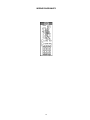
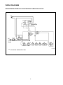
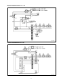
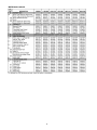
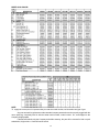
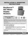
OPERATING AND
INSTALLATION
INSTRUCTIONS
CATALOG NO.: RM-001
Effective : 01-15-02
Replaces: 03-15-01
Models 136-1826
MODEL
SERIAL NUMBER
INSTALLATION DATE
START UP DATE
FOR YOUR SAFETY
Do not store or use gasoline or other flammable vapors or liquids or other combustible
materials in the vicinity of this or any other appliance. To do so may result in an explosion
or fire.
WARNING
Improper installation, adjustment, alteration, service or maintenance can cause property
damage, personal injury or loss of life. Refer to the user's information manual provided
with this heater. Installation and service must be performed by a qualified installer,
service agency or the gas supplier.
FOR YOUR SAFETY
WHAT TO DO IF YOU SMELL GAS
* Do not try to light any appliance.
* Do not touch any electrical switch; do not use any phone in your building.
* Immediately call your gas supplier from a neighbor's phone. Follow the gas
supplier's instructions.
* If you cannot reach your gas supplier, call the fire department.
IMPORTANT WARNING
THE HEATER MUST BE INSTALLED IN ACCORDANCE WITH THE INSTRUCTIONS IN THIS MANUAL. WARRANTY WILL NOT APPLY TO UNITS NOT INSTALLED, OPERATED OR MAINTAINED ACCORDING TO THESE
INSTRUCTIONS. THE INSTALLATION MUST CONFORM TO THE AUTHORITIES HAVING JURISDICTION AND/
OR WITH THE LATEST EDITIONS OF THE NATIONAL FUEL GAS CODE ANSI Z223.1, THE NATIONAL
ELECTRIC CODE ANSI/NFPA 70.
Rheem Commercial Water Heater Products
Ruud Commercial Water Heater Products
One Bell Road • Montgomery, AL 36117
(205) 260-1500
Part No. 240454
INDEX
3
4
7
8
9
10
12
16
18
20
21
22
23
24
25
26
27
28
29
29
30
31
33
34
35
39
44
COPPER SANIMASTER AND TYPHOON HOT WATER HEATERS
Specification Data
INTRODUCTION
INSTALLATION GUIDELINES
Base Requirements
Combustible Construction Clearances
Combustion Air Supply
Outdoor Venting
Indoor Venting
Power Venting
Outdoor Heaters
Vent Damper Installation
Piping (Gas and Water)
Cold Water Supply
Hot Water Supply Heater
Piping Diagram - 1 Heater 1 Tank Thermostat Supplied
Piping Diagram - 1 Heater 2 Tank
Piping Diagram - 1 Heater 3 Tank
Piping Diagram - 1 Heater 4 Tank
Piping Diagram - 2 Heater 1 Tank Uses Special Thermostat & Well
Description of Controls in General
Operating Controls
Tankstat Temperature Control
Electrical
Start-Up
General Safety Precautions
Lighting Instructions
Inspection and Maintenance Procedures
Burner Inspection
Venting System Inspection
Circulator (Water Pump) Inspection
Service Assistance
Trouble Shooting
Wiring Diagram
Replacement Parts List
2
COPPER SANIMASTER AND TYPHOON
HOT WATER HEATERS
Series GB
for circulating tank systems
136 through 1826 MBTUH
Model Applications
Hot water Supply Heaters are designed to provide hot water service to a variety of applications when used in
conjunction with an appropriately sized storage tank. Models are available for indoor or outdoor installations, and
controls and pump are factory tested and mounted.*
Construction Features
1. All copper high efficiency heat exchanger.
2. Factory mounted pump suited for a wide variety of water conditions.*
3. Flow Switch included on all models.
4. All models feature an energy saving pump control.
5. Glass-lined cast iron headers to handle the most aggressive water conditions.+
6. All units are tested and certified to ANSI Z21.10.3 and carry National Board Stamps HLW.
7. Factory installed pressure relief valve.
8. Temperature pressure gauge and tankstat are included.
9. All inputs over a 400,000 BTU feature intermittent pilot ignition.
10. Models available for Natural or LP Gas.
* Pump shipped separate in carton on Models 136 through 399.
+ Model 136 features Bronze Headers.
3
SPECIFICATION DATA
MBH Natural Gas
MODEL
STYLE
InOutDoor
Door
136
181
•
•
•
•
264
331
•
•
•
•
399
512
•
•
•
•
627
726
•
•
•
•
825
926
•
•
•
962
1083
•
1125
1178
•
Input
136.0
1337
1413
•
1467
1570
•
1630
1758
•
Output
112.0
148.0
216.0
181.0
264.0
148.0
216.0
334.0
399.0
274.0
327.0
334.0
399.0
274.0
327.0
511.5
627.0
419.4
514.0
511.5
627.0
419.4
514.0
726.0
825.0
595.0
676.5
726.0
825.0
595.0
676.5
926.0
759.0
1083.0
888.0
1178.0
966.0
961.7
788.6
1124.7
922.0
1222.5 1002.4
1287.0 1055.0
•
1336.6 1096.0
1413.0 1158.5
•
1467.0 1203.0
ELECTRICAL RATINGS
Model
Size
136-264
With Pump
3.4 amps @ 120V(1/8 hp pump)
331-399 3.6 amps @ 120V(1/6 hp pump)
512-1826 7.9 amps @ 120V (1/2 hp
pump)
MBTUH PROPANE GAS†
Model
Size
Multiplier
136-399
512-825
Same as natural gas
.94
926-1826
.92 Indoor
.955 Outdoor (Input)
.92 Outdoor (Output)
† Multiplier x Nat. MBTUH =
Pro. MBTUH
1570.0 1287.0
•
1630.0 1336.6
1758.0 1441.5
•
•
Input
136.0
181.0
264.0
•
•
Typhoon
(Outdoor)
Output
112.0
•
1223
1287
1826
Sanimaster
(Indoor)
1825.6 1497.0
Rated inputs are suitable for up to 2000 feet elevation. For elevations above 2000 feet, reduce input 4% for each
1000 feet above sea level. These heaters are tested and certified to ANSI Standard Z 21.10.3
4
5
Reference
to
Drawing
1
2
3
4
MODEL
SIZE
136
181
264
331
399
512
627
726
825
926
962
1083
1125
1178
1223
1287
1337
1413
1467
1570
1630
1758
1826
Indoor
Outdoor
•
•
•
•
•
•
•
•
•
•
•
•
•
•
•
•
•
•
•
•
•
•
•
•
•
•
•
•
•
•
•
•
Width
A
24-1/8
18-1/4
22-3/8
25-3/4
29-1/4
32-3/4
37-1/2
41-5/8
45-3/4
52-3/8
52-3/8
59-1/4
59-1/4
63-5/8
63-5/8
68-5/8
68-5/8
74-7/8
74-7/8
81-1/8
81-1/8
89-3/8
Height
Overall
B
45
62-5/8
62-7/8
63-3/4
65-3/8
57
57
57
57
76-1/8
78-1/8
78-1/8
80-1/8
80-1/8
83-1/8
85-1/8
Jacket Gas
Water
Height Conn. Connection
J
C
G
H
30-1/8
1/2
1-1/4
12-1/16
38
3/4
1-1/2
11-1/8
38
3/4
1-1/2
10-3/4
38
3/4
1-1/2
12-1/2
38
3/4
1-1/2
33
1
2
33
1
2
33
1
2
33
1
2
1
2-1/2
23-5/8
33-1/2
1
2-1/2
1
2-1/2
23-5/8
33-1/2
1
2-1/2
1
2-1/2
23-5/8
33-1/2
1
2-1/2
1-1/4
2-1/2
23-5/8
33-1/2 1-1/4
2-1/2
1-1/4
2-1/2
23-5/8
33-1/2 1-1/4
2-1/2
1-1/4
2-1/2
23-5/8
36-1/2 1-1/4
2-1/2
1-1/4
2-1/2
36-1/2 1-1/4
23-5/8
2-1/2
6
SHIPPING
WEIGHT
LBS (APPROX)
Flue
Dia.
K
6
6
7
8
9
10
12
12
14
25-3/8
29-1/2
34-1/4
38-1/2
14
28
16
32
16
32
18
36
18
36
18
36
20
40
L
9-1/4
Less Pump
W/Pump
160
182
205
225
244
475
485
635
645
785
705
865
745
925
805
980
875
1080
945
1130
985
1160
1035
210
232
255
275
294
530
540
690
700
840
760
920
800
980
860
1035
930
1130
1000
1190
1040
1220
1090
A. INTRODUCTION
WE RECOMMEND THAT THIS MANUAL BE REVIEWED THOROUGHLY BEFORE INSTALLING THE
WATER HEATER. SHOULD ANY QUESTIONS ARISE, NOT COVERED BY THIS DATA, CONTACT YOUR
LOCAL DISTRIBUTOR OR THE SERVICE DEPARTMENT AT THE FACTORY.
MODEL IDENTIFICATION
The model number of the water heater is found on the rating plate. Each model number identifies the application,
the construction and the function of the water heater , and provides a positive means of identification for application,
installation, operation, service and parts of the unit in a minimum amount of time.
RECEIVING EQUIPMENT
On receiving equipment it is suggested that you
• Review packing slip for the number of packages.
• Inspect for concealed damage immediately.
• Advise carrier, in writing, of shortages or damage.
• Claims are filed by the receiver against the carrier. The carrier, not the shipper, is responsible for any
shortage or damage whether visible or concealed.
B. INSTALLATION GUIDELINES
INSTALLATION REGULATIONS
THE INSTALLATION MUST CONFORM WITH THESE INSTRUCTIONS, REQUIREMENTS OR CODES OF
AUTHORITIES HAVING JURISDICTION, THE LATEST EDITION OF THE NATIONAL FUEL GAS CODE, ANSI
Z223.1 AND THE NATIONAL ELECTRICAL CODE.
ANY ALTERATION OR MODIFICATION TO THE WATER HEATER, ITS COMPONENTS OR ITS INTENDED
APPLICATION MAY VOID THE WARRANTY EXTENDED WITH THE PRODUCT BY THE MANUFACTURER.
WARNING:
Improper installation, adjustment, alteration, service or maintenance can damage the
water heater, or create a hazard resulting in asphyxiation, explosion or fire.
WATER FLOW
Low water content heat exchangers require continuous flow for proper operation.
WATER CONDITIONS:
Domestic Hot water heaters are designed for operation with various water conditions. Corrosive water that has
high chlorine content or other chemicals require that the tubes in the heat exchanger be cupro-nickel. Provide us
with an analysis of water where this potential exists.
7
BASE REQUIREMENTS
Indoor water heaters must be installed on a level noncombustible surface, except as noted below. Do not install
on carpeting. Heater sizes 926 to 1758 Typhoon (Outdoor) are supplied with a combustible flooring base as
standard. The following chart lists the part number required for a combustible base, for water heaters supplied
without a combustible base.
COMBUSTIBLE FLOOR BASE
BOILER
136
181
264
331
PART
001749
058313
058314
058315
BOILER
399
512
627
726
PART
058316
056199
056200
056201
BOILER
825
962
1125
1223
PART
056202
059233
059234
059235
BOILER
1337
1467
1630
1826
PART
059236
059237
059238
059239
Fig. #8148.1
Fig. #8276
Hollow concrete cinder block; align holes and leave ends open.
Alternative method for providing a non-combustible base.
HEATER WITH COMBUSTIBLE
FLOOR SHIELD
HEATER INSTALLATION
ON CONCRETE BLOCKS OR TILE
8
COMBUSTIBLE CONSTRUCTION CLEARANCES
The water heater should be positioned to provide the minimum clearances from combustible surfaces and to
provide sufficient space for servicing the unit as follows.
(h) 1-in. glass fiber or mineral wool
batts sandwiched between two sheets
0.024 sheet metal with ventilated air
space
(e) 0.024 sheet metal with ventilated air
space
(d) 3 1/2-in. thick masonry wall with ventilated air space
9
9
5
42
6
6
3
42
4
4
3
42
6
6
6
42
4
4
2
42
4
4
3
42
4
4
3
42
4
4
3
42
181-399
Rear
Left Side
Right Side
Indoor Top
Outdoor Top(1)
12"
12"
12"
39"
9
9
9
39
6
6
6
39
4
4
4
39
6
6
6
39
4
4
4
39
4
4
4
39
4
4
4
39
4
4
4
39
512-825
Rear
Left Side
Right Side
Indoor Top
Outdoor Top
12
18
6
36
(1)
9
12
5
36
6
9
3
36
4
6
3
36
6
6
6
36
4
6
2
36
4
6
3
36
4
6
3
36
4
6
3
36
926-1826
Rear
Left Side
Right Side
Indoor Top
Outdoor Top
24
24
24
24
(1)
16
16
16
24
12
12
12
24
8
8
8
24
8
8
8
24
8
8
8
24
8
8
8
24
8
8
8
24
8
8
8
24
136
(g) 0.024 sheet metal with ventilated
air space over 0.024 metal with
ventilated air space
12"
12"
6"
42"
(f) 1/2-in. thick insulation board with
ventilated air space
Rear
Left Side
Right Side
Indoor Top
Combustible Surfaces
(b) 1/2-in. insulation board over 1-in.
glass fiber or mineral wool batts
(c) 0.024 sheet metal over 1-in. glass fiber
or mineral wool batts reinforced with wire
on rear face with ventilated air space
PROTECTED SURFACES
(a) 3 1/2-in. thick masonry wall without ventilated air space
MINIMUM CLEARANCES:
Clearances to surfaces installed
in rooms which are large (2) in
comparison with size of heater.
(1) Unobstructed.
(2) Large rooms are defined as having a volume at least 16 times the total volume of the heater.
(3) Installation clearances for heaters in rooms not large in comparison with the heater size shall be as listed
under combustible surfaces and shall not be reduced by the protection methods.
SERVICING CLEARANCES:
24" in front of heater for removal of burner tray.
18" on side opposite water connection for deliming of Heat Exchanger on
Models 181-1826 only.
9
COMBUSTION AND VENTILATION AIR SUPPLY
CAUTION: Combustion air must not be contaminated by corrosive chemical fumes which can damage the heater
and void the warranty.
IMPORTANT: Adequate air must be provided for proper combustion and ventilation of the surrounding area. An
inadequate supply of combustion air will result in incomplete combustion and eventual sooting of the heater.
Insufficient ventilation will cause excessive heat and rapid deterioration of electronic and electrical components.
Equipment rooms should be provided with TWO permanent air supply openings directly connected to outside air.
Each opening must have a minimum FREE area of one square inch per 4000 BTU per hour input of the total input
rating of all equipment in the room. Local codes or authorities having jurisdiction should be consulted for the following
table.
RECOMMENDED MINIMUM AIR OPENINGS
NET
BOILER
FREE
BOILER
SIZE
AREA
SIZE
136
34
512
181
47
627
264
66
726
331
84
825
399
100
962
All area shown in square inches
NET
FREE
AREA
128
157
182
207
241
BOILER
SIZE
1125
1223
1337
1467
1630
1826
NET
FREE
AREA
282
306
335
367
408
457
For other conditions refer to the latest edition of the National Fuel Gas Code ANSI Z 223.1. Net free area, sq. in.
requires data from louver manufacturer based on resistance of screening, if provided.
OUTDOOR INSTALLATIONS
MODEL 136
MODEL 181-399
Step 1: Remove the front (4) screws
Step 2: Line up outdoor top vent opening over heater
vent opening.
Step 3: Lower outdoor top onto unit lining up slots in the
outdoor top with screws holes in jacket top.
Step 4: Reinstall (5) screw to secure jacket top and
outdoor top to unit.
VENT TERMINAL (Outdoor) Stackless Top Installation
1. Insert tabs into keyhole (4 places).
Pagoda Top
(Shipped
Loose with
Heater)
Fig. # 8114
10
2. Snap tabs into keyholes so as not to pull out.
MODELS 926-1758
Heater shipped with outdoor vent terminal factory
installed.
INDOOR HEATERS
Indoor Installations
MODEL 136
Step 1: Shut off main electrical per switch to heater.
Step 2: Turn heater manual switch located in upper
control panel to the "OFF" position.
Step 3: Shut off gas supply and water supply to the
heater.
Step 4: Mount drafthood on boiler and attach with the 4
sheet metal screws provided. Drafthood should
be positioned with the vent sensor located on
the front left side as shown.
Step 5: Remove plastic plug from left side of boiler
jacket and install the plastic grommet provided.
Step 6: Route flue sensor wire harness through the
grommet installed in Step 5.
MODELS 512 - 825
Step 1: Lower outdoor "Stackless" top on to unit.
Position top so it is centered on unit from
side to side and front to rear.
TEMPERATURE
SENSOR
SENSOR
SHIELD
MOUNTING
SCREWS
HARNESS
ASSY.
JACKET
TOP
CONTROL
PANEL
HEATER
ON/OFF
SWITCH
Fig. # 8166.1
LOWER
DOOR
Step 2: Tighten the (4) screws (Shown below) until
they come in contact with the unit jacket top,
then evenly tighten all (4) screws to secure to
unit.
GROMMET
Fig. # 8946
JACKET TOP
FASTENING
SCREW
Fig. # 8233
11
Step 7: Remove door and locate wire from roll out sensor to Hi Limit with the male/female connector.
Fig. #8947
Step 8: Disconnect male/female connector and attach to the 2 wires from drafthood vent sensor harness.
MODELS 181-399
VENT TERMINAL/INDOOR STACK INSTALLATION
1. Remove the louvered jacket top by removing
four (4) #10 flat head screws.
2. If originally installed, remove "Pagoda" top
from the louvered jacket top.
3. Place the inner stack adapter panel over the
flue collector inside the heater. Make sure
the flanged side of the flue opening is up.
4. Turn the stack (draft hood) up side
down and set it down bottom side up.
5. Turn the jacket top panel (removed in step 1) up
side down and place it through the stack.
6. Attach the three (3) mounting brackets to the
stack using the screws provided and the holes
that are pre-drilled in the stack. Make sure the
brackets are positioned with the flange near the
top side of the stack (see illustration).
Caution must be taken not to over tighten and
strip the screw threads.
7. Turn the assembled stack and jacket top, right side
up. The jacket top will be trapped between the
brackets and the top of the stack. Place the stack
over the inner adapter panel flanged hole and lower
the louvered jacket top panel back into its original
position. Reinstall the four (4) green #10 flat head
screws removed in step 1 above.
DRAFTHOOD
SCREW HOLE
LOCATION
3-1/4"
JACKET TOP PANEL
(part of the heater)
#10 SHEET METAL SCREW (3)
MOUNTING BRACKET (3)
INNER STACK ADAPTER PANEL
FLUE COLLECTOR
(part of heater)
Fig. #8246.5
12
MODELS 181-399
Step 1.
Step 2.
Step 3.
Step 4.
Step 5.
Step 6.
Step 7.
Step 8.
Shut off main electrical power switch to heater.
Turn heater manual switch located in upper control panel to the "OFF" position.
Shut off gas supply and water supply to the heater.
Mount drafthood on top of boiler as shown on page 8. Drafthood should be positioned with the vent
sensor located on the front right side as shown.
Remove plastic plug from left side of boiler jacket and install plastic grommet provided.
Route flue sensor wire harness through the grommet installed in Step 5.
Remove door and locate wire from roll out sensor to hi limit with the male/female connector.
Disconnect male/female connector and attach to the 2 wires from draft hood vent sensor harness.
Fig# 9350
Fig# 9349
HEATER BEFORE
DRAFTHOOD
INSTALLATION
HEATER AFTER
DRAFTHOOD
INSTALLATION
MODELS 512 - 825
Locate and assemble as shown below. Secure with
screws supplied in envelope in carton
Fig. #8167.0
13
MODELS 962 - 1826
Locate and assemble as shown below. Secure with screws supplied in envelope in carton.
Fig. #8265.0
WARNING:
Indoor heaters require a drafthood that must be connected to a vent pipe and properly vented to the outside.
Failure to follow this procedure can cause fire or fatal carbon monoxide poisoning.
Vent piping the same size or larger than the draft hood outlet is recommended, however, when the total vent height
is at least ten (10) feet (draft hood relief opening to vent terminal), the vent pipe size may be reduced as specified
in Chapter 10 of the National Fuel Gas Code, ANSI Z223.1. As much as possible avoid long horizontal runs of vent
pipe and too many elbows. If installation requires horizontal non-vertical runs, the vent pipe must have a minimum
of 1/4 inch per foot rise and should be supported at not less than five foot intervals. Plumbers tape, criss-crossed,
will serve to space both horizontal and vertical piping. Gas vents supported only by the flashing and extending above
the roof more than five feet should be securely guyed or braced to withstand snow and wind load. We recommend
use of insulated vent pipe must terminate with a vent cap which complies with the local codes or, in the absence of
such codes, to the latest edition of the National Fuel Gas Code, ANSI Z223.1.
The discharge opening must be a minimum of three feet
vertically from the roof surface and at least two feet higher than any
10' OR LESS
part of the building within ten feet. Vent stack shall be at least five
VENT CAP
feet in vertical height above the drafthood outlet. The vent cap
location shall have a minimum clearance of 4 feet horizontally from,
2' MIN
and in no case above or below, unless a 4-foot horizontal distance
2' MIN
is maintained, from electric meters, gas meters regulators and relief
equipment.
The weight of the vent stack or chimney must not rest on the
5' MIN
heater draft hood. Support must be provided in compliance with
VENT PIPE
applicable codes. The heater top and draft hood must be readily
removable for maintenance and inspection. Vent pipe should be
adequately supported to maintain proper clearances from combustible construction.
Type "B" double wall or equivalent vent pipe is recommended.
DRAFT HOOD
However single wall metal vent pipe may be used as specified in the
latest edition of the National Flue Gas Code ANSI Z223.1.
HEATER
Fig # 8119
14
(d) Place in operation the appliance being inspected.
Follow the lighting instructions. Adjust thermostat
so appliance will operate continuously.
At the time of removal of an existing heater, the following
steps shall be followed with each appliance remaining
connected to the common venting system placed in
operation, while the other appliances remaining connected to the common venting system are not in operation.
(e) Test for spillage at the draft hood relief opening
after 5 minutes of main burner operation. Use the
flame of a match or candle, or smoke from a
cigarette, cigar or pipe.
(a) Seal any unused openings in the common venting
system.
(f) After it has been determined that each appliance
remaining connected to the common venting system properly vents when tested as outlined above,
return doors, windows, exhaust fans, fireplace
dampers and any other gas burning appliance to
their previous conditions of use.
(b) Visually inspect the venting system for proper size
and horizontal pitch and determine there is no
blockage or restriction, leakage, corrosion and other
deficiencies which could cause an unsafe condition.
(c) Insofar as is practical, close all building doors and
windows and all doors between the space in which
the appliances remaining connected to the common venting system are located and other spaces
of the building. Turn on clothes dryers and any
appliance not connected to the common venting
system. Turn on any exhaust fans, such as range
hoods and bathroom exhausts, so they will operate
at maximum speed. Do not operate a summer
exhaust fan. Close fireplace dampers.
(g) Any improper operation of the common venting
system should be corrected so the installation
conforms with the latest edition of the National
Fuel Gas Code, ANSI Z223.1. When resizing
any portion of the common venting system,
the common venting system should be resized
to approach the minimum size as determined
using the appropriate tables in Part 11 of
the National Fuel Gas Code, ANSI Z223.1.
Manifolds that connect more than one heater to a
common chimney must be sized to handle the combined
load.
Consult available guides for proper sizing of the manifold
and the chimney. At no time should the area be less than
the area of the largest outlet.
Fig. #7043.1
15
POWER VENTING
Heaters may be connected to systems requiring mechanical draft exhaust fans. The installation must be
engineered by competent personnel in accordance with the latest edition of ANSI Z 223.1, local codes and with the
supplier of the fan.
Particular attention must be given to the type of vent pipe used, its size and location. Suitable interlocks must
be provided to prevent heater operation until the fan is operating as designed.
OUTDOOR WATER HEATERS
The point from where the flue products exit the heater must be a minimum of four (4) feet below, four (4) feet
horizontally from or one (1) foot above any door, window or gravity inlet to a building. The top surface of the heater
shall be at least three (3) feet above any forced air inlet, or intake ducts located within ten (10) feet horizontally.
Fig. #8245.1
HIGH WIND CONDITIONS (Outdoor Units Only)
In areas where high winds are frequent, it may be necessary to locate the heater a minimum of 3' from high vertical
walls, or install a wind break so the heater is not in direct wind current.
VENT DAMPER INSTALLATION
(MODELS 136 THROUGH 264) WHERE REQUIRED
LOCATION
The vent damper must be located in the vent so that
it serves only the appliance for which it is intended.
If improperly installed, a hazardous condition, such
as an explosion or carbon monoxide poisoning, could
result. Make certain that it is mounted in an accessible
location at least 6 in. (152.4 mm) from any combustible
material or the heat exchanger and that the position
indicator is in a visible location.
The vent damper must be installed after the appliance
draft hood, as close to the draft hood as practicable, and
without modification of the draft hood.
Fig. # 8182.0
16
MOUNTING
On vertical vents, the vent damper may be mounted with the actuator in any position. On horizontal vents, do
not mount the actuator either directly above or directly below the vent pipe; mount the vent damper actuator to the
side of the vent.
The vent damper is set up for a continuous pilot system. If the vent damper is installed on an intermittent Pilot
or Direct Spark Ignition equipped system, the energy savings of the vent damper can be improved by plugging the
hole in the vent damper blade using the knockout plug, Part No 105612R, provided in the parts envelope.
DO NOT plug the hole if installing the vent damper on a continuous pilot system as this will create a hazardous
condition.
INSTALLING THE VENT DAMPER IN HORIZONTAL &
VERTICAL VENTS.
D80B GENERAL WIRING DIAGRAM
INSTALL THE VENT DAMPER TO SERVICE ONLY THE SINGLE APPLIANCE FOR WHICH IT IS INTENDED. IF
IMPROPERLY INSTALLED, A HAZARDOUS CONDITION, SUCH AS AN EXPLOSION OR CARBON MONOXIDE
POISONING, COULD RESULT.
VENT DAMPER
THE VENT DAMPER MUST BE INSPECTED AT LEAST
ONCE A YEAR BY A TRAINED, EXPERIENCED SERVICE TECHNICIAN.. THE NAME OF THE PERSON
WHO ORIGINALLY INSTALLED YOUR VENT DAMPER
IS SHOWN ON THE INSTALLATION LABEL. DAMPER
MUST BE IN OPEN POSITION WHEN HEATER MAIN
BURNERS ARE OPERATING.
NORMAL OPERATION SUMMARY
For safe, efficient operation, the vent damper and all
flue product carrying areas of the appliance must be
checked annually, with particular attention given to deterioration from corrosion or other sources. Check vent
damper operation as follows:
Damper position
indicator
1. When the furnace or heater is off, check that the vent
damper position indicator points to the closed position, Fig. 4.
2. Turn the thermostat or controller up to call for heat
and check that the vent damper indicator points to
the open position, Fig. 4.
3. Turn the thermostat or controller down again and
check that the vent damper position indicator returns to the closed position.
DAMPER OPEN
DAMPER CLOSED
FIG.4-VENT DAMPER POSITION INDICATOR
SHOWING OPEN & CLOSED POSITIONS.
17
PIPING: General. Consult particular heater section for specific information.
a. GAS
Gas piping must be installed in accordance with the latest edition of the National Fuel Gas Code ANSI
Z 223.1 and other local or regulatory agency codes that have jurisdiction.
1. Check heater rating plate for
• Correct Fuel Gas
• Rated input to meet local conditions such as altitude, gas specification, etc.
2. Piping from meter must be of sufficient size to provide the required amount of gas at flowing
pressures as follows:
Gas
Natural
Propane
BTU/CF
1000
2500
SP. GR
0.60
1.53
Minimum Flowing Pressure
7" W.C.
12" W.C.
Maximum Shut-off Pressure
14" W.C.
14" W.C.
PIPE SIZES
Fuel
Length(feet)
0-100
Nat.
100-200
200-300
0-100
Model
136
181
264
331
399
512
627
726
825
926
962
1083
1125
1178
1223
1287
1337
1413
1467
1570
1630
1758
1826
3/4
1
1-1/4
1-1/4
1-1/4
1-1/2
1-1/2
2
2
2
2
2
2
2-1/2
2-1/2
2-1/2
2-1/2
2-1/2
2-1/2
2-1/2
2-1/2
2-1/2
2-1/2
1
1-1/4
1-1/4
1-1/2
1-1/2
2
2
2
2
2-1/2
2-1//2
2-1/2
2-1/2
2-1/2
2-1/2
3
3
3
3
3
3
3
3
1-1/4
1-1/4
1-1/2
1-1/2
1-1/2
2
2
2
2-1/2
2-1/2
2-1/2
2-1/2
2-1/2
3
3
3
3
3
3
3
3
3
3
3/4
1
1
1-1/4
1-1/4
1-1/4
1-1/2
1-1/2
2
2
2
2
2
2
2
2
2
2
2
2
2
2
2
Propane
100-200
200-300
1
1
1-1/4
1-1/4
1-1/4
1-1/2
1-1/2
2
2
2
2
2
2
2
2
2-1/2
2-1/2
2-1/2
2-1/2
2-1/2
2-1/2
2-1/2
2-1/2
1
1-1/4
1-1/4
1/1/2
1-1/2
1-1/2
2
2
2
2
2
2
2
2-1/2
2-1/2
2-1/2
2-1/2
2-1/2
2-1/2
3
3
3
3
Chart is based on:
0.5" W.C. Pressure Drop Natural Gas
0.6" W.C. Pressure Drop Propane Gas
Fitting provided in gas line have equivalent length of pipe, in feet, as follows:
Size
3/4
1
1-1/4
1-1/2
2
2-1/2
3
4
Elbow
2.5
3
4
4.5
5.5
6.5
8
12
Tee
5
6
8
9
12
14
17
22
3. All gas piping must be tested after installation with air or an inert gas and all connections should be
checked using a soapy solution.
18
CAUTION: The heater and its manual shut off valve must be disconnected from the gas supply during any pressure
testing of that system at test pressures in excess of 1/2 psig (3.45 KPA). Dissipate test pressure in the gas supply
line before reconnecting the heater and its manual shut off valve to gas supply line. FAILURE TO FOLLOW THIS
PROCEDURE MAY DAMAGE THE GAS VALVE. OVER PRESSURED GAS VALVES ARE NOT COVERED BY
WARRANTY. The heater and its gas connections shall be leak tested before placing the appliance in operation.
Use soapy water for leak test. Do NOT use open flame.
Test piping as follows:
Pressure 1/2 PSIG (14" W.C.) or less - isolate heater by closing the manual shut-off valve prior to applying
pressure.
Pressure in excess of 1/2 PSIG (14" W.C.) - The heater must be disconnected from the gas system.
Water heaters having gas train components that have diaphragms in their construction are supplied with a bleed
line connection that must be connected to the outside atmosphere as required by the National Fuel Gas Code. Under
NO circumstances shall bleed lines terminate in the gas utilization equipment flue or exhaust system.
Fig.#8185.1
Burner Manifold Pressures. The gas pressure regulator supplied with the heater is factory set to provide a manifold
pressure, as measured with a manometer, of 3.7 in. W.C. for Natural Gas and 10.5 in. W.C. for Propane. If adjustment
is required to obtain these pressures remove cap and turn screw clockwise to increase pressure, counter- clockwise
to decrease pressure.
19
b. WATER
Water piping should be installed according to the local code requirements, ASHRAE, ASPE and BOCA
or other regulatory agencies.
COLD WATER SUPPLY
The cold water supply piping, to the heater must be adequate to handle the design load requirements of the hot
water system. The following table illustrates the flow and minimum pipe sizes.
Model
Size
136
181
264
331
399
512
627
726
Flow
GPM
22
30
42
53
63
82
85
85
Min
Pipe
NPT
1-1/4
1-1/2
1-1/2
1-1/2
1-1/2
2
2
2
Model
Size
825
926
962
1083
1125
1178
1287
1337
Flow
GPM
85
90
90
90
90
90
90
90
Min
Pipe
NPT
2
2-1/2
2-1/2
2-1/2
2-1/2
2-1/2
2-1/2
2-1/2
Model
Size
1413
1467
1570
1630
1758
1826
Flow
GPM
90
90
90
90
90
90
Min
Pipe
NPT
2-1/2
2-1/2
2-1/2
2-1/2
2-1/2
2-1/2
It is recommended that a gate valve be installed in the cold water supply line adjacent to the heater. If Local Codes
require a check valve - provisions must be made for thermal expansion.
A minimum pressure of 30 PSIG must be maintained in the system to prevent damage to the heater due to lack
of water circulation caused by vapor formation at suction side of the system pumps.
NOTE: Should the cold water supply be interrupted, for any reason, the gas supply must be manually shut off to
prevent heater damage. When the service is restored the lines must be vented to eliminate accumulated air.
20
HOT WATER SUPPLY HEATER
Model 136- 1826
The heater is direct fired and used with a storage tank. The model number indicates the BTU/holds input. (i.e. an
1826 holds input of 1,826,000 BTU/ HR)
See specification and dimension information on pages 4, 5 and 6.
TANK TEMPERATURE CONTROL
1. The tank temperature controller is shipped loose for installation in the field. It is found in the burner tray.
2. Install in the tapping provided in the storage tank as shown.
3. Wire the "TH" leads, provided in the boiler control box, to the tank temperature controller. DO NOT WIRE IN
SERIES WITH 115 VOLT SUPPLY TO THE HEATER.
NOTE: The "TH" wires are in the 24 volt control circuit. DO NOT connect to the 115 volt circuit.
4. Set temperature to 140°F or to desired tank temperature.
21
SEQUENCE OF OPERATION
1. Power to heater and recirculation pump.
2. Control switch, located on heater control box, placed in "ON" position.
a. High limit controller circuit closed.
b. Tank temperature controller calls for heat.
c. Pump relay energized starting heater pump.
d. Flow switch activated, if sufficient flow is determined, sending power to
e. The ignition relay, S8600.
f. The pilot is energized and when proven lit.
g. Spark to pilot stops and
h. The main gas opens allowing the burners to light.
3. Tank temperature reaches desired temperature.
a. Controller opens circuit.
b. Ignition relay de-energizes shutting off main and pilot gas.
c. Heater pump continues to operate until residual heat in the heater is dissipated.
d. Stack temperature drops below 140°F. A stack sensor, a part of the energy saving control, opens
the pump relay circuit shutting down pump.
4. Heater waits for next call for heat.
INSTALLATION WATER HEATER PLUMBING:
The Recirculation pump , supplied by the installer should be sized according to heater input Model # ie. 825
would require 8.25 GPM. This pump is in addition to the pump supplied with the heater. The pump should
be set for constant recirculation. DO NOT WIRE to heater or tank operating controls.
PIPING DIAGRAM-1 HEATER 1 TANK THERMOSTAT SUPPLIED
Fig. # 8054-RHEEM
22
PIPING DIAGRAM-1 HEATER 2 TANK
* PIPING MUST BE EQUAL BETWEEN TEES AND TANKS.
NOTES:
1.
2.
3.
4.
5.
Plumb all swing check valves in gravity closed position.
Minimum pipe size equal to heater inlet/outlet connection size (between heater and tanks).
Pipe sizes between tanks are to be based on estimated GPM flow rates (Max. 10 FPS Vel.)
Pipe all relief valves to drain or as local codes require.
Duplex manifold kit & 115 gallon jacketed and insulated storage tanks available from factory.
23
PIPING DIAGRAM-1 HEATER 3 TANK
Fig. # 8067-RHEEM
* PIPING MUST BE EQUAL BETWEEN TEES AND TANKS.
NOTES:
1.
2.
3.
4.
5.
Plumb all swing check valves in gravity closed position.
Minimum pipe size equal to heater inlet/outlet connection size (between heater and tanks).
Pipe sizes between tanks are to be based on estimated GPM flow rates (Max. 10 FPS Vel.)
Pipe all relief valves to drain or as local codes require.
Duplex manifold kit & 115 gallon jacketed and insulated storage tanks available from factory.
24
PIPING DIAGRAM-1 HEATER 4 TANK
* PIPING MUST BE EQUAL BETWEEN TEES AND TANKS.
NOTES:
1.
2.
3.
4.
5.
Plumb all swing check valves in gravity closed position.
Minimum pipe size equal to heater inlet/outlet connection size (between heater and tanks).
Pipe sizes between tanks are to be based on estimated GPM flow rates (Max. 10 FPS Vel.)
Pipe all relief valves to drain or as local codes require.
Duplex manifold kit & 115 gallon jacketed and insulated storage tanks available from factory.
25
PIPING DIAGRAM-2 HEATER 1 TANK SPECIAL THERMOSTAT AND WELL
NOTES:
1.
2.
3.
4.
5.
6.
Plumb all swing check valves in gravity closed position.
Minimum pipe size to be (1) size larger than heater inlet/outlet connection size.
Pipe all relief valves to drain or as local codes require.
115 gallon jacketed and insulated storage tanks available from factory.
When two heaters are paralleled, do not use factory supplied thermostats. Order thermostat part
number 600887 and Well PN 650590 from factory. See electrical wiring on page 29.
Heaters with 2" or 2-1/2" manifold size may require more than one storage tank. Consult factory for
proper storage sizes.
26
DESCRIPTION OF CONTROLS IN GENERAL
ENERGY SAVING PUMP CONTROL
The energy saving pump control is an electronic
device that allows the operator to set the desired time for
the pump to run after the heater shuts off. The time is
factory-set at 7 minutes and it can be re-adjusted in the
field anywhere from 3 to 10 minutes.
In a conventional system, when the tankstat is
satisfied, the main gas valve closes, but the pump
continues operating. With the energy saving pump
control, the heater pump is programmed to continue
running for an optimum period of time in order to absorb
the residual heat from the combustion chamber and use
it in the system.
The pump then shuts off until the next call for heat is
received from the tankstat.
ELECTRONIC IGNITION
The intermittent ignition device conserves energy by
automatically extinguishing the pilot when desired temperature is reached. When additional heat is needed, the
pilot re-ignites electrically, eliminating costs of maintaining a constant pilot. To assure safe operation, the gas
valve cannot open until the pilot lights and is proven.
Fig. # 8929.1
Economaster Control
Fig # 9331
Ignition Module Electronic Safety
27
TANKSTAT TEMPERATURE CONTROL
This is a bulb immersion type device that will
regulate the water temperature in the storage tank.
When the water temperature rises to the set point, the
switch opens and shuts off the main burners. As the
water cools down, the switch closes and turns on the
main burners again to maintain the desired water temperature.
FLOW SWITCH
Dual purpose control shuts off heater in case of
pump failure or low water flow condition.
Factory mounted on all boilers except 136 and wired
in series with main gas valve.
NOTE: Flow switch will not operate if flow is less than
12 GPM.
Fig. # 8643
Temperature Control
Fig. #9317
HIGH LIMIT
The high limit is also a bulb immersion type device
that limits the water temperature in the heater outlet. It
will shut off the main burners when the heater outlet water
temperature exceeds the high limit setting, and cycles
on again when the water temperature drops to the set
point, less the differential.
Models are equipped with manual reset high limit on
all models except 136. Model 136 is equipped with an
automatic reset high limit.
Flow Switch
HIGH LIMIT (Manual Reset)
The manual reset high limit is similar to the automatic reset high limit, except the reset button on the front
of the case must be pushed in to allow the main burners
to operate again after a high limit shutdown.
Models are equipped with manual reset high limit.
The temperature setting is usually set 30° to 40°F above
the operating temperature.
Fig. # 9314
Manual Reset High Limit
28
100% PILOT SAFETY (IID Units)
All heaters employ electronic devices, which close
the main gas valve within 8/10 of a second whenever the
pilot flame is interrupted. Pilot flame is automatically lit
when the device is powered. Unit performs its own safety
check and opens the main valve only after the pilot is
proven to be lit.
ELECTRICAL
Heater electrical characteristics are
Primary: 115 volt 60 Hz 1 phase.
Secondary: Control Circuit: 24 volts.
CAUTION: All wires prior to disconnection when servicing controls. Wiring errors can cause improper and
dangerous operation. Verify proper operation after
servicing.
Single Stage Tankstat
NOTES:
1. Field Installed ground to inside of junction box.
2. If any of the original wire as supplied with the heater
must be replaced, it must be replaced with 105°C
wire or its equivalent.
DANGER - SHOCK HAZARD
make sure electrical power to the heater is disconnected
to avoid potential serious injury or damage to components.
The heater is normally wired for 120 Volts. The
voltage is indicated on the tie-in leads. Consult the wiring
diagram shipped with the boiler in the instruction packet.
The "TH" leads are for the remote tank control connections 24 Volts are supplied to this connection through the
heater transformer. DO NOT attach line voltage to the
"TH" leads on sized 133-1826. Before starting heater
check to insure proper voltage to boiler and pump.
WARNING:
Before starting check to insure proper voltage is supplied
to heater and pump.
Heater must be electrically grounded in accordance with
the National Electrical Code ANSI/NFPA No 70 latest
edition.
Use wiring diagram supplied with the heater.
START-UP
1. Fill system with water, flush, to remove particles
and other foreign objects that can cause pump
damage.
2. Check electric supply characteristics
a. Voltage to heater: 115 volts 60 Hz. 1 phase
15 amp circuit breaker.
b. Voltage to pump:
3. Set operating and limit controls.
ON-OFF OPERATION
Set storage tank tankstat to desired temperature.
This is the operating control. See Operation sequence,
page 22.
Single Stage Tankstat
HEATER DPST TANKSTAT CONTROL WIRING
Heater must be electrically grounded in accordance
with National Electrical Code ANSI/NFPA No. 70.
29
General Safety Precautions
To meet commercial water use needs, the thermostat on
this water heater is adjustable up to 210°F. However,
water temperatures over 125°F. can cause severe burns
instantly or death from scalds. This is the preferred
starting point for setting the control for supplying general
purpose hot water.
The following chart details the relationship of water
temperature and time with regard to scald injury and may
be used as a guide in determining the safest water
temperature for your applications.
Temperature
120°F.
125°F.
Safety and energy conservation are factors to be considered when setting the water temperature on the thermostat. The most energy efficient operation will result when
the temperature setting is the lowest that satisfies the
needs consistent with the application.
Time to Produce Serious Burn
More than 5 minutes
1-1/2 to 2 minutes
130°F.
135°F.
About 30 seconds
About 10 Seconds
140°F.
145°F.
Less than 5 seconds
Less than 3 seconds
150°F.
155°F.
About 1-1/2 seconds
About 1 second
Table courtesy of Shiners Burn Institute
TIME/TEMPERATURE RELATIONSHIPS IN SCALDS
The temperature of the water in the water heater can be
regulated by setting the temperature dial on front of the
thermostat. To comply with safety regulations the
thermostat was set at its lowest setting before the water
heater was shipped from the factory. The illustration
below illustrates the thermostat and how to adjust the
water temperature.
Water temperature over 125°F can
cause severe burns instantly or
death from scalds.
To adjust the water temperature, insert a small
straight screwdriver into
slotted screw in hole in front
of thermostat and turn
wheel to desired setting.
Thermostat is adjustable up
to 210°F.
Children, disabled and elderly are at
highest risk of being scalded.
CAUTION!! - Hotter water
increases the risk of
SCALDING!
See instruction manual before setting temperature at water heater.
! DANGER
Feel water before bathing or showering.
There is a Hot Water SCALD Potential if the thermostat
is set too high.
Temperature limiting valves are
available, see manual.
NOTE: When this water heater is supplying general
purpose hot water requirements for use by individuals, a
thermostatically controlled mixing valve for reducing
point of use water temperature is recommended to
reduce the risk of scald injury. Contact a licensed
plumber or the local plumbing authority for further information.
Maximum water temperatures occur just after burner has
shut off. To find hot water temperature being delivered,
turn on a hot water faucet and place a thermometer in the
hot water stream and read the thermometer.
30
LIGHTING INSTRUCTIONS FOR HEATERS WITH ELECTRONIC IGNITION (IID)
For Models with Manual Gas Valves 512, 627, 726
FOR YOUR SAFETY READ BEFORE OPERATING
WARNING:If you do not follow these instructions exactly, a fire or explosion may result causing
property damage, personal injury or loss of life.
A.
This appliance is equipped with an ignition device which
automatically lights the pilot. Do not try to light the pilot
by hand.
B.
BEFORE OPERATING Smell all around the appliance
area for gas. Be sure to smell next to the floor because
some gas is heavier than air and will settle on the floor.
WHAT TO DO IF YOU SMELL GAS
Do not try to light any appliance.
Do not touch any electric switch:
do not use any phone in your building.
Immediately call your gas supplier from your neighbor’s
phone. Follow the gas supplier’s instructions.
*
*
*
*
If you cannot reach your gas supplier, call the fire department.
C. Use only your hand to push in or turn the gas control
knob. Never use tools. If the knob will not push in or turn
by hand, do not try to repair it, call a qualified service
technician. Force or attempted repair may result in a fire
or explosion.
D. Do not use this appliance if any part has been under
water. Immediately call a qualified service technician to
inspect the appliance and to replace any part of the
control system and any gas control which has been
under water.
OPERATING INSTRUCTIONS
1.
2.
3.
4.
5.
6.
7.
8.
STOP! Read the safety information above on this label.
Set the thermostat on the lowest setting.
Turn off all electric power to the appliance.
This appliance is equipped with an ignition device which
automatically lights the pilot. Do not try to light the pilot
by hand.
Remove boiler door panel.
For Robertshaw gas valve: Turn gas control knob
clockwise
to “OFF”.
For Honeywell Gas Valve: Turn gas control knob clockwise
to “OFF". Make sure knob rest against
stop.
For Honeywell Gas Valve:
Push in gas control knob slightly and turn clockwise
to “OFF”. Knob cannot be turned to
“OFF”
unless knob is pushed in slightly. Do not force.
Wait five (5) minutes to clear out any gas. Then smell
for gas, including near the floor. If you smell gas, STOP!
Follow “B” in the safety information previously stated. If
you do not smell gas, go to the next step.
For Robertshaw Gas Valve: Turn gas control knob
counter clockwise
to “ON”.
For Honeywell Gas Valve: Turn gas control knob
counter clockwise
from “OFF” until it
stops. Push in gas control knob and continue
rotating counter clockwise
to “ON”
position. Make sure knob rest against stop.
GAS CONTROL
KNOB SHOWN
IN "ON" POSITION
GAS INLET
Fig. # 8082
9.
10.
11.
12.
Replace boiler door panel.
Turn on all electric power to the appliance.
Set thermostat to desired setting.
If the appliance will not operate, follow the instructions
“To Turn Off Gas To Appliance” and call your service
technician or gas supplier.
GAS CONTROL
KNOB SHOWN
IN "ON" POSITION
GAS INLET
Fig. # 8080
TO TURN OFF GAS TO APPLIANCE
1.
2.
3.
4.
Set the thermostat to the lowest setting.
Turn off all the electric power to the appliance if service
is to be performed.
Remove door panel.
For Robertshaw Gas Valve: Turn gas control knob
clockwise
to “OFF”.
5.
31
For Honeywell Gas Valve: Turn gas control knob clockwise
to “OFF”. Make sure knob rest against
stop.
For Honeywell Gas Valve:
Push in gas control knob slightly and turn clockwise
to “OFF”.
Replace heater door panel.
LIGHTING INSTRUCTIONS FOR HEATERS WITH
ELECTRONIC IGNITION (IID)
FOR MODELS WITH AUTOMATIC GAS VALVES
726-1826
1. Close all gas valves. Turn off electric power
supply. Wait five (5) minutes.
2. Open manual pilot valve. Turn on electric power.
Pilot is automatically lighted.
3. Open main gas valve.
4. Set temperature controls to desired temperature.
TO SHUT DOWN
Close all manual gas valves. Turn off electric
power.
PILOT SHUT-OFF
VALVE CONTROL
SHOWN IN THE
"ON" POSITION
TO PILOT(S)
MAIN GAS SHUT-OFF
VALVE SHOWN IN THE
"ON" POSITION
32
INSPECTION AND MAINTENANCE PROCEDURES
Six Months:
1. Heat Exchanger Surfaces.
a. Shut off electric and gas supply to heater.
b. Examine external surfaces
2. Preliminary examination maybe done by using a
mirror and a light in the burner area.
3. Remove venting, heater jacket top, flue collector and
heat exchanger baffles. Remove inspection baffles.
c. If surfaces are sooted or foreign material is lodged
in fins, cleaning is required.
To clean:
A. Remove burner tray.
- Disconnect gas control valves and pilot valves by
breaking at unions.
- Disconnect wiring from gas valves.
- Remove burner tray retention screws.
- Slide tray from heater carefully to avoid disturbing
or damaging IID.
B. Remove tube bundle.
- Disconnect inlet-outlet header by removing flange
nuts and retaining bolts.
- Slide tube bundle away from inlet-outlet header,
taking care to avoid damage to refractory and
sheetmetal.
- Washdown external surfaces of tube bundle.
- Inspect interior surfaces of tubes. Clean deposits
over 1/16" thickness.
- Clean tubes using tube cleaning kit.
C. Ream tubes by using auger bit.
D. Complete cleaning by wire brushing to remove all
debris.
E. Immerse tube bundle in non-inhibited descale solvent.
It is a good practice to make a periodic inspection of the
heater. It is recommended that the home owner or user
checks the heater after the first and third month of
operation, and then on an annual basis, or more often if
desired. It is also recommended to have a qualified
service agency check the heater before each heating
season, or at anytime there may be an indication of a
problem.
1. Keep heater area free from combustibles and
flammable liquids.
2. Be certain that All combustion and ventilation air
openings are free and clear of all obstructions.
Screens, covering same, must be clean.
Monthly:
1. Make visual inspection of burner flames.
Fig. #8144
a. Flame should be blue with light yellow tips.
b. Yellow flame indicates clogged air openings.
c. Lifting of flame indicated high gas pressure.
Check using manometer at 1/8 in. NPT tapping
located between the gas valve and the burners.
Pressure should be 3.7 in. W.C.
2. Inspect and operate all controls and gas valves.
3. Visually inspect system for water leaks
NOTE: DO NOT wire brush external surfaces. Steam
cleaning is a recommended procedure.
F. Replace tube bundle using the reverse of the
above procedures.
G. Before replacing burner tray clean burners.
4. Flow switch should be removed and checked.
5. Low water cutout, if provided, should be removed
and checked.
33
DANGER: Keep heater area clear and free from combustibles and flammable materials. Do not obstruct the
flow of combustion and ventilating air into the heater
enclosure. Failure to observe these safety precautions
can cause fire, explosion, or asphyxiation.
2. Venting System Inspection
Visually inspect the venting system. Make sure the
vent connections are secure and have not become
disengaged. Look for any indication of corrosion, or
carbon (soot) streaks which could cause leakage of
products of combustion into the living space. Inspect the
vent terminal outside the building. Make sure it is not
damaged to cause blockage or restriction of the flue gas.
Observe for any indication of soot. The presence of soot
accummulation in the vent terminal would indicate an
abnormal operating condition. This should be investigated and corrected by a qualified service agency.
3. Circulator (Water Pump) Inspection
The circulator is permanently lubricated and thus,
will not require any lubrication. Inspect for evidence of
water leakage. This should be corrected to prevent any
possible damage to electrical components of the boiler.
1. Burner Inspection
Clean the main burners and air louvers of dust, lint
and debris. With burner in operation, make a visual check
of the burner flame and the pilot flame (when equipped).
Yellow flames indicate some restriction of combustion air
openings. A bright orange, luminous flame is not normal
and can cause sooting under prolonged operation.
Should this condition be observed, contact immediately
a qualified service agency to correct the problem.
CAUTION: In case of a prolonged power failure during
freezing weather conditions, heater and piping system
must be drained completely to avoid possible damage to
the system.
To prevent the potential freezing damage to the
system, it is recommended that the following system
shut down procedure be performed.
SYSTEM SHUT DOWN PROCEDURE
1. Set the thermostat to "OFF" or the lowest setting.
2. Turn off all electric switches to the heater.
3. Turn off all gas valves supplying gas to the heater.
Refer to operating instruction label on the heater.
4. Shut off the water supply to the heater piping system
loop.
5. Open drain valve on the heater to remove water
from the heater and the piping circuits.
NOTE: It may be necessary to open the purge valves
and/or manual air vents to facilitate complete drainage of
water from the heating system.
4. Service Assistance
If service is required on the heater, contact your
local service agency. It is important and very often will
save time if you state the model number, serial number
and type of gas used. This information will be found on
the nameplate of the heater.
Fig. #8204.1
34
TROUBLE SHOOTING
PROBLEM
CAUSE
SOLUTION
When thermostat is turned on nothing
happens.
IID Pilot is not lit….…………………….
No power to the heater………………….
Check pilot gas line.
Check the circuit breaker, outdoor controller, etc., upstream of heater.
If power to Leads L1 and L2 of transformer, but no power on 24V side, replace.
Jumper thermostat , replace with new if
heater fires.
If power to toggle switch, but not through
switch, replace.
If power to relay, but not operating, replace.
Bad
Transformer…………………………
Inoperative thermostat…………………
Inoperative toggle switch………………
Inoperative relay…………………………
Thermostat in on position causes relay
and pump to operate, but heater does
not fire.
"A" valve closed…………………………
Plugged bleed line………………………
Flow switch open……………………….
Broken
pump
pler……………………
cou-
Open "A" valve.
Loosen bleed line and clean.
Low flow. Bleed air from the system.
Adjust bypass valve to allow proper flow
to activate the flow switch. If flow problem persists due to system design,
primary-secondary pumping should be
considered.
Replace coupler. Inspect bearing assembly, and if frozen lubricate or replace.
Shut down on low water cutoff, caused
by air………………………………………
Gas valve defective…………………….
Bleed air reset button.
Check for power to gas valve. If valve
has power but will not open, replace the
valve.
Low water due to leaking………………
Air in system…………………………….
Inspect for leakage and repair.
Inspect for leakage and repair. Install
an automatic air vent in top of low water
cutoff.
Continuous shut down of low water cut
off.
35
TROUBLE SHOOTING
Problem
Possible Cause
1.
Electrical:
•
Main power
Heater will not operate:
Action
•
Manual reset switch.
•
Operating controller.
•
Controller in-operative.
•
Flow Switch
Check circuit breaker, fuses, etc.
Power at boiler control switch should
be 115 volts.
Check all controls. If reset is tripped
determine reason and correct.
Check power to all controls with
voltmeter. Adjust to desired operating temperatures.
Remove sensor. Check for immersion or sensing.
Replace if faulty.
Check pump for operation.
Mechanical:
Open shutoff cock(s)
Loosen bleed line and clean.
•
Gas Line
Plugged bleedline on pressure
regulator, gas valves, etc.
Broken pump coupler.
•
1.
Gas valve will not open:
Diaphram type.
Check bleed line. Clean. Check
solenoid. Replace if defective.
2.
Motorized type
Check auxiliary switches.
a. Auxiliary switch;
b. Valve closed switch.
Power should be 115 volts.
•
•
Check reason for failure.
Inspect bearing assembly, shaft and
impeller.
Replace coupling.
Note: Actuator is not field repairable. If problem is other than switch(es)
replace.
2.
Pilot burner will not light
3.
Combination type
Check controller.
Intermittent Ignition Module
(IID)
Check power to 25 VAC input
terminal
1. If 25 VAC:
- Check for 1/8" spark @ pilot.
a. Spark ok:
• Check gas supply.
• Burner orifice.
• Dampness @ electrode
or high tension wire.
• Check for 25 VAC @
PV; MV/PV terminals.
1. Voltage @ 25 VAC
- Replace pilot valve.
2. Voltage not @ 25 VAC
- Replace module.
2. No 25 VAC @ input terminal.
- Check transformer output.
a. 25 VAC
• Check limit circuit.
b. No 25 VAC
• Replace transformer.
36
Electrical continued
3.
4.
Pilot lights -
Pilot lights -
Main burner cyles.
Intermittent Ignition Module
•
Poor ground connection
Main burners do not light.
3. Mechanical Modulating Valve.
4. Failure to pump.
5. Pump capacity insufficient.
6. Rapid coupling wear.
7. Pump loses prime.
8. Overload.
9. Mechanical noise.
37
Check ground connection.
Install or replace.
Check for spark
1. Spark stays on while pilot is on.
• Check for loose ignition wire.
• Check for poor ground.
• Check flame coverage of both
spark and grounded electrodes.
• If okay replace ignition module
2. Spark goes out and pilot stays on:
• Check voltage at MV; MV/PV
terminals.
- Voltage @ 24 VAC - replace
main gas valve.
- Voltage not at 24 VAC - replace
module.
Voltage should read 24 VAC.
If valve does not open:
1st operator - replace valve
2nd operator- replace operator
assembly.
Check dial setting on valve and set to
meet requirements.
Unit keeps cycling on electrical limits adjust temperature setting on valve.
Pump not primed.
Pump rotation wrong direction.
• Check motor leads- reverse
to obtain proper rotation.
Speed too low• Check for proper voltage at
motor.
Total head too high.
Check for
• Air leaks in suction line.
• Clogged impeller.
• Strainer clogged.
• Excessive suction lift.
• Insufficient positive suction
head.
Total head greater than design.
Worn impeller.
Misaligned or bent shaft,
Sagging motor mounts.
Check for air leaks.
Check water seal in stuffing box.
Check suction lift and pump design
curves.
Check head on pump if too low
throttle discharge.
Check alignment. Correct if found.
Check for vapor binding and reduce
temperature to meet design.
Check shaft and bearings.
Check piping for correct alignment
and support.
ELECTRICAL (ELECTRONIC IGNITION IID)
MODELS 512 - 1826
C. Trouble shooting for S8600 control.
Refer to the following chart for future
servicing or the ignition control.
WARNING HIGH VOLTAGE
For qualified Technicians ONLY
NOTE: Some heaters may be equipped with an ignition module that
shuts off pilot gas if pilot fails to light. To reset, interrupt power to heater.
Intermittent Pilot System
TROUBLESHOOTING HONEYWELL S8600
START
TURN GAS SUPPLY OFF.
TURN THERMOSTAT
(CONTROLLER) TO CALL
FOR HEAT
POWER TO MODULE
(24 V NOMINAL)
YES
SPARK ACROSS
IGNITER/SENSOR GAP
YES
NOTE: Before troubleshooting, familiarize yourself with the start-up and checkout
procedure.
NO
Check line voltage power, low voltage transformer, limit controller,
thermostat (controller) and wiring.
Pull ignition lead and check spark at module.
NO
Spark Okay?
YES
• Check ignition cable, ground wiring, ceramic insulator and gap, and correct.
• Check boot of the ignition cable for signs of melting or buckling. Take protective
action to shield cable and boot from excessive temperatures.
TURN GAS SUPPLY ON
PILOT BURNER LIGHTS?
YES
NO
• Check that all manual gas valves are open, supply tubing and pressures are
good, and pilot burner orifice is not blocked.
• Check electrical connections between module and pilot operator on gas control.
• Check for 24 Vac across PV-MV/PV terminals on module. If voltage is okay,
replace gas control; if not, replace module.
NOTE: If S8600H goes into lockout, reset system. Lockout is used on L.P.G. models.
SPARK STOPS WHEN
PILOT IS LIT?
YES
NO
MAIN BURNER LIGHTS?
YES
NO
SYSTEM RUNS UNTIL
CALL FOR HEAT ENDS?
YES
•
•
•
•
•
•
•
Check continuity of ignition cable and ground wire.
Clean flame rod.
Check electrical connections between flame rod and module.
Check for cracked ceramic flame rod insulator.
Check that pilot flame covers flame rod and is steady and blue.
Adjust pilot flame.
If problem persists, replace module.
• Check for 24 Vac across MV-MV/PV terminals. If no voltage, replace module.
• Check electrical connections between module and gas control. If okay, replace
gas valve or gas control operator, i.e. pilot gas valve, flow switch etc.
NOTE: IF S8600H goes into lockout, reset system.
NO
• Check continuity of ignition cable and ground wire.
NOTE: If ground is poor or erratic, shutdowns may occur occasionally even though
operation is normal at the time of checkout.
• Check that pilot flame covers flame rod and is steady and blue.
• If checks are okay, replace module.
CALL FOR HEAT ENDS
SYSTEM SHUTS OFF?
YES
TROUBLESHOOTING
ENDS
NO
• Check for proper thermostat (controller) operation.
• Remove MV lead at module; if valve closes, recheck temperature controller and
wiring; if not, replace gas valve.
Repeat procedure until troublefree operation is obtained.
38
WIRING DIAGRAM KEY
39
WIRING DIAGRAMS
WIRING DIAGRAM - MODELS 136 -264 WITH ENERGY PUMP SAVING CONTROL
Fig. # 2288e
40
WIRING DIAGRAM - MODELS 331 - 399
Fig. # 1930e
WIRING DIAGRAM MODELS 512 - 627
Fig. # 1924e
41
WIRING DIAGRAM MODELS 512-726
Fig. # 2194e
WIRING DIAGRAM MODELS 726 - 825
Fig. #2297e
42
WIRING DIAGRAM MODEL 825 - 1826
WIRING DIAGRAM MODELS 962 - 1826
Fig. # 1967e
43
REPLACEMENT PARTS LISTS
MODEL 136 GB ONLY
44
MODEL 136 GB ONLY
45
MODELS 181, 264, 331, 399 GB
46
47
MODELS 181, 264, 331, 399 GB
48
MODELS 181, 264, 331,339 GB
49
MODELS 512, 627, 726, 825 GB
50
MODELS 512, 627, 726, 825 GB
51
MODELS 512, 627, 726, 825 GB
52
MODELS 926-1826 GB
53
MODELS 926-1826 GB
54
MODELS 926-1826 GB
NOTE:
To supply the correct part it is important that you state the model number, serial number and type of gas.
Any part returned for replacement under standard company warranties must be properly tagged with the
return parts tag, completely filled in with the heater serial number, model number etc., and shipped to the
Company freight prepaid.
If determined defective by the Company and within warranty, the part will be returned in kind or equal
substitution, freight collect. Credit will not be issued.
55