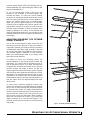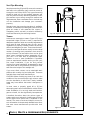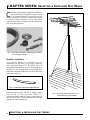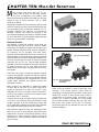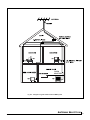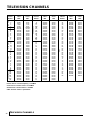
1
Off-Air Antenna
Installation
Guide
Solutions For
The Professional Installer
INTRODUCTION
T
he information in this manual has been
gathered from some of the most experienced
antenna installation professionals in the
country and compiled by Channel Master ® field
engineers. It is intended for technicians who are, or
plan to become professional antenna installers. Any
handy “do-it-yourself” consumer can mount an
antenna, run transmission line and pull in some kind
of a signal. But only a professional can select and
precisely install the correct antenna and assure his
customers years of superior TV/FM reception.
Back in the 1940s, TV antennas were actually
manufactured by hand at the installation site. Each
antenna was assembled, piece by piece, at the
customer’s home. Channel Master eliminated this
time-consuming labor by introducing the first
preassembled TV antenna, providing excellent
reception in all areas and at reasonable prices.
Today medium-to-high gain, broadband antennas are
essential for good reception. Even the most expensive
color TV or FM stereo receiver can’t perform to full
potential without the strong signals that only a
quality antenna system can provide.
Advanced antenna theory and design is not included
in this manual. The greatest emphasis is on practical,
time-tested methods and procedures for properly
installing TV and FM antennas. With this foundation
of knowledge, you can build your reputation as a
professional antenna installer–one who is capable of
assuring his customers the finest performance from
today’s sophisticated TV and FM equipment.
All Channel Master VHF/FM and UHF/VHF/FM
antennas have sensitivity classifications such as
“fringe,” “suburban,” “deep fringe,” etc. These classifications are designed to indicate at what distance
from a TV transmitter the antenna will provide the
best reception. Our antenna lab has computed the
following chart as a general guide:
Area Designation
For VHF
For UHF
100+ miles
60+ miles
100 miles
60 miles
Fringe
80 miles
45 miles
Near Fringe
60 miles
40 miles
Far Suburban
50 miles
35 miles
Suburban
45 miles
30 miles
Far Metropolitan
30 miles
25 miles
Metropolitan
25 miles
15 miles
Deepest Fringe
Deep Fringe
Additional performance information is available from
Channel Master upon request. Write to:
Channel Master
P.O. Box 1416
1315 Industrial Park Drive
Smithfield, NC 27577
Or contact us through our site on the World Wide
Web at:
www.channelmaster.com
A WORD ABOUT ANTENNA SPECIFICATIONS
Sensitivity ratings are based on optimum conditions
over unobstructed terrain. What lies between a transmitter and an antenna installation will have a direct
bearing on what type of antenna is appropriate.
Factors to consider are: the power output and height
of a transmitting antenna tower, the type of terrain
between the tower and the receiving antenna, and the
size and number of buildings that lie in the path of the
transmission.
INTRODUCTION
1
CHAPTER ONE: ANTENNA SELECTION
B
asically, a receiving antenna is a device for
intercepting the electromagnetic waves or
signals, sent from a transmitter. Some antennas
are simple vertical poles; others are small wire loops
attached to the back of a TV set.
In this manual, we will discuss the outdoor TV antenna
design with which most of us are familiar: a central
horizontal boom with small elements attached at
right angles.
The main receiving element of an antenna is called
the dipole (Fig. 1-1). All of the other antenna parts are
designed primarily to help the dipole do its job. The
dipole consists of two half-elements to which the
transmission line is attached. It is the element around
which the other antenna parts are designed and
positioned.
BASIC TV ANTENNA TYPES
TV antennas can be grouped in four major functional
categories: VHF/FM, UHF, UHF/VHF/FM, and FM only
combinations.
VHF and FM Antennas
Most VHF (Very High Frequency) antennas are
engineered to receive TV channels 2 through 13. They
also will receive the FM radio band, which is located
between TV channels 6 and 7. FM only antennas are
available also (Figure 1-6). Channels 2 through 6 are
known as the low band. Channels 7 through 13 are
referred to as the high band. Some VHF antennas are
designed to receive only one band, either the low or
high band. Antennas designed to receive both the low
band and the high band are called VHF/FM broadband antennas (Figure 1-2).
TV channel 1 “disappeared” in the early days of TV
because of a change in frequency assignments by the
Federal Communications Commission (FCC). A
reshuffling of FM, Amateur, and other bands removed
TV from the frequencies previously reserved for TV
channel 1. Because the other 12 TV channels were
already numbered 2 through 13, the channel 1
designation simply was dropped.
UHF Antennas
UHF (Ultra High Frequency) antennas are designed to
receive TV channels 14 through 69, the UHF TV band.
The UHF TV band originally extended from channel 14
to channel 83. However, the FCC now has reassigned
channels 70 through 83 (also known as the translator
band) to mobile communications use. Although there
still are many antennas capable of receiving all 82
channels, the translator band (former TV channels
70-83) is useless to the TV viewer. UHF TV antennas
come in a wider variety of shapes and sizes than
2
ANTENNA SELECTION
VHF/FM antennas. The wider variety of UHF designs
(Figure 1-3) is possible because they don’t require the
long elements that VHF/FM antennas do.
Combination UHF/VHF/FM Antennas
Combination UHF/VHF/FM TV antennas are designed
to receive both the UHF and the VHF/FM bands.
Although the use of separate antennas for each band
is ideal for peak reception, high-performance
UHF/VHF/FM combination models are readily
available and are becoming increasingly more
popular. Examples of combination UHF/VHF/FM
antennas are shown in figures 1-4 and 1-5.
HOW TO SELECT THE RIGHT ANTENNA
There are many bands and hundreds of TV antenna
models available. However, choosing the right one
is relatively easy if you are aware of a few basic
reception and TV antenna characteristics.
First, “good reception,” or production of a snow-free
color TV picture, requires a signal level of about
1000 microvolts (µV) = 1 millivolt (mV). To deliver
this signal level to the receiver, the antenna requires
a certain antenna gain. The amount of gain required is
dependent on the distance between the station’s
transmitting antenna and the receiving antenna. The
required type of antenna therefore depends on the
channels to be received and the distance and direction of the customer’s home from the transmitting
antennas. These facts are readily available for any
area, but be sure your information is accurate and
complete. Call a local TV station if you have questions. Most TV stations are willing to help TV antenna
installers because they also benefit from the
improved reception to the station’s viewers.
Be sure to discuss with your customers the number
and types of channels that are receivable. This may
sound basic, but your customers may not understand
the difference between VHF/FM and UHF. They also
may not be aware that with the right equipment they
may be able to receive out-of-town channels, some of
which may carry sports programs that are locally
blacked out. The most important points to remember
when selecting an antenna are its gain, sensitivity
classification, directivity, and front-to-back ratio.
Gain
The gain of an antenna indicates the relative strength
of signal it can deliver to a receiver. Most manufacturers list the gain of their antennas in decibels (dB). The
higher the antenna gain, the stronger the signal at the
antenna output terminals. In most cases, the larger the
antenna, the higher the gain.
Fig. 1-2. A VHF/FM broadband TV antenna.
Fig. 1-1. The principal parts of a basic Yagi-type TV antenna.
Fig. 1-6. FM antenna.
Fig. 1-3. Various designs of UHF TV antennas.
Fig. 1-5. Channel Master ® CROSSFIRE® UHF/VHF/FM TV antenna.
SMARTenna®
Channel Master® SMARTenna® UHF/VHF Antenna
Fig. 1-4. Channel Master ® QUANTUM ® model UHF/VHF/FM antenna.
ANTENNA SELECTION
3
If you are in doubt about the amount of gain required,
select an antenna that is slightly larger than you think
is actually needed. The performance of all
components deteriorates slightly during the years
they are exposed to rain, sun, wind, and corrosion.
Consequently, to ensure quality reception for a longer
period, choose an antenna with a little more gain than
is necessary. (Note: Excessive gain may cause
overloading. Therefore, choosing the antenna with
the highest gain might create more reception
problems than it cures.)
Sensitivity classifications are used to indicate the
type of reception area for which the antenna is
designed. Certain ranges of gain are best suited for
certain types of areas. The appropriate range of gain
for a specific area is what a manufacturer is indicating
when labeling an antenna. Outer Suburban or Near
Fringe Table 1-1 is a chart of typical sensitivity
classifications. It indicates in miles, how close an
antenna must be to the transmitter to produce the
best signal level. The classifications are somewhat
general because reception conditions at various sites
within a particular type of area may be different.
An antenna with a relatively narrow beamwidth
generally is best suited for areas where interference
from sides is a problem. An antenna with a broad
beamwidth is best suited for areas where a broad
beam is needed to capture the signals from widely
separated stations, and where interference is
minimal. Beamwidth information, if included by the
manufacturer, is usually displayed by use of polar
plots like the one in Figure 1-6.
Selecting the most suitable antenna becomes easy
with experience, but selecting quality materials
should be the first decision to make before starting
any installation. High-performance color reception
usually requires highly sensitive equipment. In the
long run, it pays to use the finest equipment
available, from the antenna down to the receiver end
of the transmission line. The slight additional cost
should be considered an investment in longer system
life and optimum performance.
DIRECTIVITY
Direcitivity is the ability of an antenna to intercept
signals from only one direction and reject those from
other directions. Directivity indicates the antenna’s
ability to intercept signals arriving at its front and
reject signals coming from the sides and rear.
Generally, the more highly directive an antenna, the
better it can reject signals from the sides and rear.
The front-to-back ratio of an antenna can be helpful
when attempting to determine its directivity.
Front-to-back ratio is expressed in decibels (dB) and
can be found in the literature accompanying a new
antenna. This ratio indicates an antenna’s ability to
reject signals coming from the rear (rear rejection).
For example, an antenna with a front-to-back ratio of
25 dB will receive about 18 times more signal strength
from the front than from the back.
In most cases, an acceptably accurate estimate of an
antenna’s directivity can be made by comparing its
specified front-to-back ratio with the relative sensitivity
classifications listed in Table 1-1.
The sensitivity classifications in Table 1-1 are intended
only as general guidelines for evaluating directivity.
Other factors, such as the antenna’s beamwidth, can
affect its directivity. Beamwidth is related to an
antenna’s overall gain and indicates how wide or
narrow the antenna’s reception area is. For example,
if two antennas have the same front-to-back ratio, the
one with the highest overall gain will have the
narrowest beamwidth and consequently, will be the
most directive.
Fig. 1-6. A polar plot like shown here reveals the directivity and
beamwidth of an antenna.
Area Designation
Deepest Fringe
Deep Fringe
Fringe
Near Fringe
Far Suburban
Suburban
Far Metropolitan
Metropolitan
For VHF
100+ miles
100 miles
80 miles
60 miles
50 miles
45 miles
30 miles
25 miles
For UHF
60+ miles
60 miles
45 miles
35 miles
35 miles
30 miles
25 miles
15 miles
Table 1-1. Typical Sensitivity Classifications
4
ANTENNA SELECTION
CHAPTER TWO: SAFE INSTALLATION PROCEDURES
here are extremely important safety factors to
consider. Learning and following simple safety
precautions can, quite literally, save your life.
Following safe procedures also helps prevent costly
damage to your equipment and your customer’s
property.
T
12. Carry a well-equipped first aid kit in your
truck.
No list of safety tips can cover every potential hazard.
Consequently, careful planning, common sense, and
good judgment must be used at all times.
14. Have an effective insect repellent handy
during spring and summer months. (Wipe off
your hands after applying it.)
1. Locate and avoid power lines and other wires
in the work area.
15. Any antenna mounted on 20 or more feet of
mast requires more than one person to
install.
2. Do not climb on a wet or icy roof.
3. Do not attempt high installations on windy
days.
4. Do not hesitate to turn down a job that seems
too dangerous.
5. Use only the sturdiest commercial-grade
ladders. (Types with wide, slip-preventive
rungs and bases are essential. Avoid types
with round rungs.)
6. Do not position ladders at an angle steeper
than 70˚. Steeper angles can cause a ladder to
slip sideways.
7. Dig the base of the ladder into the ground if
possible.
8. Do not place ladders on slate that is wet or
hot. Wet or sun-heated slate is very slippery.
9. Do not climb on roofs that have curled or
worn shingles. (Old shingles break easily or
pull out.)
10. Wear seasonable clothing that is neither too
tight nor too loose. Wear snugly-fitting
rubber-soled, low-heeled shoes or boots.
11. Wear a pair of durable but flexible protective
gloves whenever they will not interfere with
the work process.
13. Keep a couple of cans of wasp and hornet
spray that will shoot with a long stream.
16. Carefully survey the job before beginning the
installation to locate secure handholds,
dangerous conditions (such as power lines
and weak roofs), and the safest and most
convenient placements for ladders.
17. Do not climb onto a roof when there is no one
else around.
18. Be sure all of your helpers know and follow
safe procedures.
19. Do not step into roof valleys (the area where
two roofs join); they often are weak, even on
new homes.
20. Do not install antennas under large, overhanging tree branches if it can be avoided.
21. Buy only the best quality tools and equipment. Besides lasting longer, top-quality
tools and equipment generally do not break
or bend as readily as do cheaper products.
22. Antennas must be installed away from power
lines a distance equal to at least twice the
combined length of the mast and antenna.
23. Refuse to perform jobs that are not directly
related to the antenna installation. If you do
and a liability problem develops, your
insurance probably will not cover it.
Thoroughly plan every installation. Carefully think
through the job, and don’t take dangerous shortcuts.
SAFE INSTALLATION PROCEDURES
5
CHAPTER THREE: MOUNTING FOR OPTIMUM SIGNAL STRENGTH
I
deally, an antenna should be mounted at the point
where the signals are the strongest, though often
this is impractical or impossible. Also, the antenna
should be mounted where it can be easily serviced
should repairs or adjustments be required in the
future. So carefully “aiming” (orienting) the antenna
and adjusting its height often can overcome the
problems created by installing it in a slightly weaker
signal area.
In an area where there is a relatively short,
unobstructed signal path between the installation
and the transmitting towers, you can mount the
antenna just about anywhere and receive sufficient
signal. As you move deeper into the fringe areas
however, there may be significant differences in
signal strength at various points on the roof. This is
where careful antenna selection, precise orienting,
and accurate adjustment of the height become
essential. The careful installer should be able to
locate a spot where there is both a usable signal and
sufficiently easy access to the antenna.
Large trees can present reception problems and nearby
high-voltage power lines can cause interference that
cannot be completely eliminated. Consequently, the
further the antenna is from large trees and high-voltage
lines, the better the reception will be.
WALKING THE ROOF FOR OPTIMUM
SIGNAL STRENGTH
“Walking the roof” is usually the best way to find the
spot on the roof where the strongest signals are
present. First, attach a small TV antenna to short
mast (4-6 feet). Attach one end of a short transmission line to the antenna terminals. Attach the other
end of the transmission line to the input jack of a
field-strength meter. Then walk to the most suitable
mounting areas. Point the front of the test antenna in
the general direction of the transmitter tower(s).
Slowly, rotate the antenna while carefully watching
the field-strength meter. (Most field strength meters
are equipped with shoulder straps that free both of
your hands for manipulating the antenna.)
USING A FIELD-STRENGTH METER
A small, battery-powered portable TV is helpful for
determining general reception quality. However, there
is no better way to determine actual signal strength
than to use a field-strength meter (Figure 3-1). It is one
of the best investments you can make. The meter will
save you so much time and trouble that it will quickly
pay for itself.
6
Fig. 3-1. A field-strength meter.
Field-strength meters come with detailed operating
instructions. Below are general characteristics and
operating procedures that apply to most fieldstrength meters.
A field strength meter has an input impedance of 75
ohms. Most television antennas have an output
impedance of 300 ohms. For accurate measurements
these two impedances must be “matched.” Attach
a balun (matching transformer) to the antenna
terminals and run coaxial cable from the balun to the
meter input jack. (TV coaxial cable has an impedance
of 75 ohms.)
Most field-strength meters will measure the strength
of both VHF and UHF signals and will separately
measure each channel. Most field strength meters will
also separately measure the picture and sound signals
of each channel.
The ideal is to get the strongest signal possible. When
this is not possible and you need to sacrifice a little
strength, connect the test antenna output to a battery
operated, portable TV set and check the picture and
sound to ensure that the signal levels are adequate
for acceptable reception. The TV will also help you
better explain reception possibilities and problems to
your customers.
A field-strength meter indicates signal strength
in microvolts (uV) and decibels relative to one millivolt (dBmV). One microvolt is one-millionth of a volt,
or 0.000001 volt. The microvolt reading is probably
the easiest to use. As a general guideline, a signal
level of 50 uV at the antenna output terminals is the
weakest usable signal; however, it will require strong
preamplification to provide acceptable TV reception.
MOUNTING FOR OPTIMUM SIGNAL STRENGTH
Antenna output signals of 500 uV and above are considered adequate. Any signal level below 1,000 uV will
require preamplification.
To use the field-strength meter, orient your test
antenna in the direction of incoming signals and
activate the meter. To orient the actual installed
antenna in an area where several channels are coming
from the same general direction, aim the antenna to
obtain the highest reading with the field-strength
meter set on the highest channel to be received.
(Channel 13 is the highest VHF channel, and 69 is the
highest UHF channel.) As a result, this will orient the
shortest antenna element as well as properly align
remaining elements. Of course, if the channels are
coming from different directions, you will have to take
separate readings for each and adjust the antenna(s)
accordingly.
ADJUSTING THE HEIGHT FOR OPTIMUM
SIGNAL STRENGTH
Just as the received signal strength varies with the
mounting site and the direction in which the antenna
is pointed (oriented), the height at which the antenna
is installed will also affect signal strength. A few feet
up or down may make a big difference in the level of
the received signal(s), especially on UHF channels.
Watch your field-strength meter as you slowly raise
and lower the test antenna.
The height at which you ultimately mount the
antenna depends on two things: signal strength and
practicality. You should mount the antenna only as
high as necessary, even if your meter indicates that
the signal level continues to increase as you raise the
antenna. Choose the height at which you get the
highest signal level without having to resort to guyed
mast and other more expensive and difficult to install
equipment. Your objective should be to get as close
as possible to an unobstructed “line of sight” between
the transmitter tower(s) and the receiving antenna so
that the signal clears all large buildings and other
obstructions.
In some cases, obtaining adequate signals may
require the installation of a multiple array. A multiple
array is two or more antennas set at different heights
on the same mast (Figure 3-2). Ideally, these antennas
should be spaced seven feet apart so that they won’t
interact with each other. If this is not practical, try to
mount them at least five feet apart. When installing
more than one antenna on a mast, try to mount the
largest (heaviest) at or near the mast support. This
will help prevent excessive strain on the mast during
high winds.
Fig. 3-2. A vertically stacked antenna array.
MOUNTING FOR OPTIMUM SIGNAL STRENGTH
7
CHAPTER FOUR: TOOLS, MASTS & HARDWARE REQUIREMENTS
Tools
The majority of the tools and equipment you will need
for most installations are apparent. The following is a
list of useful tools and miscellaneous materials that
might also come in handy.
1. A complete set of nut drivers (spin-tights).
2. A set of ratchets and sockets.
3. A pocket compass, for orienting the antenna and
setting up the rotor when the compass bearing(s)
of the transmitter tower(s) is known.
4. A drill brace with a wide assortment of bits.
5. A good quality leather tool belt.
6. A crimping tool for fastening coaxial connectors.
7. Caulking compound for sealing the holes where
transmission line enters the house.
8. Roofing tar (plastic roof cement), for sealing
around screws on the roof.
9. Silicone grease for waterproofing coaxial cable
connectors.
10. A sledge hammer for driving in ground rods.
11. A level or plumb bob for ensuring that the
antenna mast is installed perpendicularly.
12. A map to aid antenna orientation. (Aircraft maps
are ideal. Most airports sell them.)
13. A strong step ladder (in addition to extension
ladders).
14. A magnetic stud finder.
15. A small, portable TV that operates on both standard house current (117 volts AC) and batteries.
Masts
Most antenna hardware catalogs list a wide variety of
mounts and masts. Most however, are variations of a
few basic types. By taking into account signal
strength and ease of installation, it’s not difficult
deciding which site, mount, and hardware to use.
A mast (Figure 4-1) is used in every installation. The
mast is the vertical tubing that supports the antenna.
Conventional masts are available in 5 and 10 foot
lengths. Telescoping mast units (Figure 4-2) are
available in 20, 30, 40 and 50 foot lengths. Each type
is available in various wall thicknesses that provide
different degrees of strength and rigidity. Your choice
will depend on the height, weight, and size of the
antenna being installed and also on wind conditions
in the area.
8
Fig. 4-1. Examples of 5 and 10
foot mast sections.
Fig. 4-2. A telescoping mast.
Both conventional and telescoping masts are available
in galvanized steel and in high-tensile, acrylic-coated
steel. Acrylic-coated masts are preferable because of
their greater strength and durability.
TOOLS, MASTS & HARDWARE REQUIREMENTS
MOUNTING SITES AND RELATED
PROCEDURES
Attic Installations
An attic installation (Figure 4-3) may work in areas
where strong signals are present. In most cases, an
attic installation is the easiest, fastest, most
economical, and most convenient installation. There
are a few conditions however that can prohibit an
attic installation. Shallow attics that are obstructed
by rafter supports may not accommodate the size
antenna required for the installation. Most attics are
not large enough to accommodate multi-antenna
arrays and rotors. Also, aluminum foil on insulation,
aluminum or steel siding, metal gutters at the attic
level, and metal lath under older plaster walls all can
interfere to some degree with reception.
Fig. 4-4.
Fig. 4-5.
Examples of swivel mounts that can be used in attic installations.
An alternative method of mounting the mast is to
flatten one end of the mast with a hammer and drill a
hole in it through which a nail, screw, or bolt can be
inserted for securing the mast to a rafter or rafter
support. However, this method requires more time
and effort than does the bracket method.
Instead of using a mast, you may suspend the antenna
from the inside of the roof with guy wires or nylon
rope. But don’t let the guy wires touch the antenna
elements. They will short out the antenna.
Once you have the antenna mounted or suspended,
you are ready to run the transmission line. If at all
possible, keep it indoors. Coaxial cable (Figure 4-6) is
the best transmission line for any antenna installation. It should be used instead of twinlead even in
attic installations. Selection and installation of the
correct transmission line is described in the chapter
beginning on page 15.
Fig. 4-3. A typical attic installation.
To determine if an attic installation is suitable, take a
test antenna, a field-strength meter and a portable TV
up into the attic and check the signal level and
picture quality. If the signal level is sufficient and
there is room enough to properly orient the antenna,
assemble the antenna in the attic and attach one end
of the transmission line to the antenna terminals.
Then prepare the mount for the antenna.
Several roof-type mounting brackets (Figure 4-4) and
swivel mounts (Figure 4-5) are adaptable for use in
attic installations. The mounting bracket is used to
attach the short mast to a rafter or rafter support.
The antenna is then mounted on the other end of the
mast. The antenna however, must not touch the attic
floor. Also, remember that the antenna should be
attached to the mast right side up, even though the
installation appears to be the reverse of an outside
installation.
Fig. 4-6. Coaxial cable, the preferred type of TV transmission line.
After you have run the transmission line, use a
compass and field-strength meter to orient the
antenna toward the signal source(s). Check the
picture and sound on all channels before you tighten
down the clamp that secures the antenna to the mast.
Some manufacturers make special antennas for attic
installations. These antennas however, tend to be
omni-directional. This means they intercept signals
equally well from all directions. Consequently, they
will also pick up interference more readily than a
good directional antenna.
TOOLS, MASTS & HARDWARE REQUIREMENTS
9
Chimney Mounts
Chimney Mounts (Figure 4-7) are used more frequently than other types of mounts, but they often are not
the best option. Although they are relatively easy to
install, the smoke and gases from a chimney can
shorten the life of the antenna and significantly
impair its performance.
A chimney installation is practical only if the chimney
is sturdy and vertical. Never mount an antenna on a
deteriorated chimney. During moderate too high
winds an unguyed mast taller than 10 feet can exert
enough leverage to break off an unstable chimney.
If you choose a chimney mount, use enough mast to
place the antenna above most of the smoke and
gases. However, to avoid overstressing the chimney,
do not mount the antenna more than 10 feet above
the top of the chimney. If the height of the antenna
must exceed 10 feet to receive satisfactory signals,
the mast must be properly guyed. (The correct method
of installing guy wires is described in Chapter 7.)
Fig. 4-7. A typical chimney mount and related hardware.
centered on the bricks – not over the mortar joint.
Pull each strap tight, line it up so that it is level, and
then tighten it just enough to hold it in place.
Before the straps are tightened completely, fasten
the mast to the mounting bracket. (It is assumed that
the antenna has already been clamped securely
to the mast, and one end of the transmission line
has been connected to the antenna terminals.) Align
the mast so that it is vertical. Then completely
tighten the mounting straps. Next, orient the antenna.
Finally, tighten the clamps that hold the mast to the
mounting. Be sure the clamps are tight enough to
prevent the mast from being rotated by the wind load
on the antenna.
Roof Mounts
There are two basic types of roof mounts: a base
mount (Figure 4-8) and a tripod (Figure 4-9).
Tripods are stronger and more rigid than base
mounts, but they are also more expensive. When
given a choice, use a tripod.
Fig. 4-8. A base-type roof mount and related hardware.
Securing the chimney-mounted antenna and minimizing the stress on the chimney requires the mounting
straps to be properly spaced. The top strap should be
placed as high up on the chimney as possible. If the
chimney has a crown or projecting cap, place the top
strap directly under it. The bottom strap should be
placed 4 feet below the top strap. If the chimney isn’t
long enough to permit this, place the bottom strap as
far down on the chimney as possible. If the mast must
be 10 feet above the chimney top, don’t use a chimney mount unless you can space the straps at least 30
inches apart. For masts less than 10 feet above the
chimney top, the straps should be spaced no less
than 24 inches apart.
Be sure the straps are level, with no kinks or twists.
The easiest way to level straps is to line them up
along the nearest course of bricks. Straps should be
Fig. 4-9. A tripod roof mount.
10
TOOLS, MASTS & HARDWARE REQUIREMENTS
However, if cost savings or limited space require it, a
properly guyed base mount will usually work. Unlike
a chimney mount, a base mount holds the mast at
only one point, the bottom. Consequently, the mast
also must be supported by guy wires, regardless of
the mast length.
Correct installation of either type of roof mount
requires great care and should not be attempted
without a helper. Both types of mounts should be
secured to the roof with either bolts or lag screws.
These should be screwed into only solid wood like a
rafter or a truss section. You can locate these with a
stud finder.
If you must fasten the mount to the roof in an area
where a bolt or screw cannot reach a rafter, send your
assistant into the attic with a large square of wood
1-1/2” thick, to act as a backing plate. Have him hold
this wood against the entry points of the screws or
bolts so that the mount is firmly anchored in both the
roof sheathing and the wooden block. This will give
the mount needed stability.
When installing a base mount, attach the base
plate to the roof in the manner just described,
and place the mast (with antenna, guy ring, and guy
wires attached), into the U-bolt that has been
fastened loosely to the mount. Do not let the bottom
of the mast touch the roof; it may tear a hole in
the shingles.
Fig. 4-11. Pitch Pad seals should be installed under the tripod legs.
opposite the direction in which the antenna is lying.
Run the end of the guy wire through the screw eye.
Have your assistant slowly raise the mast while you
pull the guy wire through the screw eye (Figure 4-10).
When the mast is vertical, the guy wire you are
holding will be approximately the right length for
permanent installation. Temporarily secure this guy
wire. Install the other guy wires while your helper
holds the mast in a vertical position. Check the mast
with a level as you tighten and permanently secure
each wire. When the mast is vertical and each guy
wire has been tightened, orient the antenna and
firmly tighten the U-bolt (clamp) on the base mount.
Tripods, as noted earlier, are a stronger, more rigid
type of roof mount. The most common tripod mounts
are 3, 5, and 10 feet high. The 3 foot tripod is most
commonly used.
A tripod mount can be installed and leveled before
the mast is inserted. It should always be mounted so
that the antenna can be folded down along the peak
of the roof. This will enable you to lower it more easily should repairs or adjustments become necessary
in the future. Even though tripods are very stable, any
tripod-mounted mast over 10 feet high should be
guyed.
Fig. 4-10. The correct method of raising a base-mounted TV antenna.
Since a base mount must be guyed, an easy way to
raise the mast is to first fasten one of the guy wire
screw eyes to the roof peak on the end of the roof
Ensure the sturdiness of the tripod by anchoring. To
protect the roof, use a pitch pad seal under each
tripod leg (Figure 4-11). Coat all lag bolts with roofing
tar or other sealant to prevent leaks around them.
Roofing tar or silicone should be used liberally
around all holes, bolts, screws, nails, and eye screws.
TOOLS, MASTS & HARDWARE REQUIREMENTS
11
Wall Mounts
Many types of wall mount brackets are available.
However, many of them are poorly made and will not
withstand more than a moderate wind. Buy only the
best quality wall mount brackets (Figure 4-12).
When installing a wall mount, space the brackets as
far apart as possible (or practical). Generally, the
farther apart you space the brackets, the stronger the
installation will be. Be sure the brackets extend out
from the wall far enough for the mast to clear the roof
eaves. As with roof mounts, screw wall mount brackets only into solid wood, and use caulking or other
durable sealant around screws.
Fig. 4-12. An example of a strong, durable wall-mount bracket.
Mounting from the Ground
Many times you will not want (or will not be able) to
mount an antenna on the roof. One of the best
alternatives to roof mounting is mounting from the
ground (Figure 4-13). With a firm base support and
one or more wall mount brackets, a ground mount
installation is exceptionally sturdy and long lasting. A
good ground mount may also eliminate the need of
guy wires.
Correctly preparing the base of a ground mount is
very important. The antenna mast should rest on
something more solid and stable than just bare earth.
If your installation site is on a solid deck or patio, the
base is already prepared for you.
When you have to prepare the base yourself, dig a
hold about 2 feet deep at the spot where the mast will
contact the ground. Remember that the base hole
must line up with the wall bracket(s) so that the mast
will be vertical. A plumb line and bob suspended from
the roof eave can be used to determine the correct
positions of the base hole and wall brackets (Figure
4-13). Use bricks or flat stones in the bottom of the
hole as a footing to prevent the base of the mast from
moving. Concrete can also be used as a footing but
you’ll have to wait for it to dry before you can put up
the mast.
Once the base is prepared, mount a wall bracket at
least 10 feet above the ground or as high as possible.
Remember, the farther apart the wall brackets are
placed, the sturdier the installation (Figure 4-13). If
there is 5 feet or more left between the first wall
bracket and the roof eave, add another wall bracket.
Be sure the base hole and the wall brackets line up so
that the mast will be vertical. This can be determined
easily by suspending a plumb bob and line from the
roof eave into the base hole. Also remember that the
wall bracket(s) must extend out from the wall far
enough so that the mast clears the roof eaves. Be sure
the screws of each wall bracket are anchored in solid
wood. Screw them into the wall studs.
12
Fig. 4-13. A ground mounted installation showing good bracket
spacing and use of a plumb line and bob.
TOOLS, MASTS & HARDWARE REQUIREMENTS
Firmly clamp the antenna to the upper end of the
mast. Insert the mast into the base hole or rest it on
the deck or patio. Vertically position the mast by
“walking” it up hand over hand. Rest it against the
wall bracket(s). Loosely fasten the mast to the wall
bracket(s). After determining that the mast is truly
perpendicular, tighten the bracket(s) a little more.
Next, orient the antenna. After the antenna has been
oriented, securely tighten the wall bracket clamps
around the mast. Finally, if a base hole is being used,
fill in the hole and firmly tamp the soil around the
base of the mast.
Telescoping Masts
A telescoping mast (Figure 4-14) is used in installations for which standard 5 or 10 foot lengths of mast
stacked together would not be sufficiently strong or
rigid. A length of telescoping mast is stronger and
more rigid than the same lengths made up of
standard mast pieces stacked together. Because of
their additional strength, some telescoping masts
used with ground mounts can be extended up to
15 feet above the roof line without requiring guy
wires. Another advantage of telescoping masts is that
they can be easily adjusted to odd heights without
having to cut the tubing.
Because telescoping masts are heavy and require firm
bottom support, they should not be used with
chimney or wall mounts. However, because ground
and roof mounts do provide bottom support,
telescoping masts can be used with these mounts
to provide additional height.
For extra strength when installing large antennas, use
a telescoping mast that is one size larger than actually
needed. This will permit you to attach the antenna to
the mast section immediately below the topmost one.
This section is larger and stronger than the topmost
section because it is reinforced by the 1-1/4” diameter
section that remains inside.
When installing telescoping masts 20 feet or shorter
in length, lay the mast on the ground and extend it to
the desired length. Prop up the small end on a stable
support and attach the antenna and transmission
line. Then connect the bottom of the mast to the base
mount and walk up the mast to its vertical position.
(Use a base mount that will swivel!)
For masts over 20 feet long, securely mount and guy
the bottom section first. Then attach guy rings and
wires to the rest of the sections. Mount the antenna
on the upper section, secure its guy ring and the
transmission line. Using a person to hold the guy
wires to each anchor point, raise each section one at
a time, starting with the top. Tighten the wires after
the mast is fully extended.
Fig. 4-15. A step ladder carefully positioned across the
roof peak and tied to the guyed mast section
permits reaching above the guyed bottom
section of a telescoping mast to attach guy
rings and guy wires to the upper
telescoping sections.
Fig. 4-14. A typical
telescoping mast.
TOOLS, MASTS & HARDWARE REQUIREMENTS
13
Vent Pipe Mounting
Vent pipe mounting (Figure 4-16) secures the antenna
and mast to the plumbing (gas) vent that comes up
through the roof of the house. This type of mounting
should be used only for the smallest antennas, and
then only when economy absolutely demands it. Vent
pipe mounts are not sturdy enough for medium and
large antennas. Even a moderate wind or ice load may
ruin the installation and damage your customer’s
property.
Standard vent pipe mounting hardware is available.
However, it should be used with great care. Most vent
pipes are made of soft materials like copper or
orangeburg, which are easily crushed or dented by
the stress exerted by the mounting bracket.
Fig. 4-16. A typical vent pipe mount and related hardware.
Towers
Antennas are mounted on towers (Figure 4-17) when
exceptional height (35 feet or more) is required for
adequate reception or when an unusually large antenna
array must be used. Although they are very sturdy
installations if properly installed, towers can be very
difficult and dangerous to erect. Tower manufacturers’
instructions and specifications usually include a large
number of warnings and precautions that must be
strictly followed. The best advice that can be given
about tower installations before attempting one of
your own, is to work with an experienced tower
installer on one or more installations. If possible,
have an experienced installer assist you with your
first tower installation. If you do find yourself
involved in a tower installation, be prepared for some
heavy work and for the possibility of having to climb
well above the height of the average roof.
If you must climb a tower, use an attachable work
platform with a safety ring and safety belt. These are
available from some tower manufacturers.
CAUTION: Before climbing any tower, first check the
condition of the structure and the guy wires to make
sure the installation is safe. Even a newly installed
tower may have defects that make it dangerous to
climb.
In most cases, a properly guyed 40 or 50 foot
telescoping mast can be substituted for a 40 to 50 foot
tower installation. It is not only easier and less dangerous to install, it is also significantly less expensive.
A detailed discussion about the various types of
towers and the procedures for installing each of them
would require more space than is available in this
manual. The most accurate and helpful sources for
such information is the extremely detailed instructions
that most tower manufacturers provide with their
towers.
Fig. 4-17. Example of an antenna tower.
14
TOOLS, MASTS & HARDWARE REQUIREMENTS
CHAPTER FIVE: SELECTING & INSTALLING TRANSMISSION LINE
Selecting and Installing Transmission Line
Transmission line or downlead, is the wire that
carries the signal from the antenna output terminals
to the receiver input terminals. Even the best antenna
and the most expensive receiver will not produce an
acceptable picture if the transmission line has not
been carefully selected and correctly installed. The
transmission line is more important than most people
realize. Color television reception is sensitive and
highly susceptible to interference from many different
sources. Transmission line that is carefully chosen
and neatly run by an installer who knows what he is
doing will reward the customer with clear, distortionfree color TV reception.
The Two Basic Types
There are two basic types of transmission line:
300 ohm twinlead and 75 ohm coaxial cable.
Fig. 5-2. A preferred type of 75 ohm coaxial TV cable and
its construction.
Most modern TV sets have a single 75 ohm VHF/UHF
input. Older TVs frequently have a 75 ohm VHF input
and a 300 ohm UHF output. In this case, a band
separator will be required. Coaxial cable has many
advantages over twinlead and is preferred by most
installers.
Most antennas are 300 ohm balanced output.
Therefore, an outdoor balun is required at the antenna
in order to use 75 ohm coaxial cable. If a preamplifier
with 300 ohm in put is used, a short length of 300
twinlead will be required between the antenna and
preamplifier. Fig. 5-3 shows examples of baluns.
300 ohm twinlead (Figure 5-1) comes in various colors
and thicknesses, is the least expensive, but requires
more careful installation, and picks up interference
signals if they are present. In modern installations, it
is only used to connect between an antenna and a
preamplifier.
Fig. 5-3. Baluns are used to match 75 ohm coaxial cable
to the output of a 300 ohm antenna and to the
TV receiver 300 ohm input terminals.
Installing Twinlead
Fig. 5-1. Standard 300 ohm TV transmission line (twinlead).
Although more expensive, 75 ohm coaxial cable
(Figure 5-2) is easier to correctly install, has a longer
life, and does not pick up interference. Coaxial cable
is round with a central conductor wire surrounded
by plastic insulating material, a braided wire or
aluminum foil sheathing, and a water-resistant outer
covering jacket.
Start the twinlead installation at the antenna and
work toward the receiver. First, assemble the antenna
according to the manufacturer’s instructions.
Carefully “snap-out” the elements and then mount the
antenna on the mast.
Attach the twinlead wire conductors to the antenna
terminals with lugs. Never twist bare wire around the
antenna terminals. It is a poor connection that will
deteriorate even more as rust and corrosion set in.
SELECTING & INSTALLING TRANSMISSION LINE
15
indoors, drive staples or tacks only in the center
portion of the insulation between the conductors. Do
not use any staples or tacks large enough to “bridge”
the conductors. This will short the conductors. Run
twinlead directly to the back of the set from the wall,
floor, or baseboard. Don’t leave more twinlead than
absolutely needed. Extra twinlead will coil up and act
as additional antennas. This causes ghosting and
signal loss.
Fig. 5-4. Twinlead inserted into a standout (standoff).
Next, pass the twinlead through a standout or
standoff (Figure 5-4). Install the standout on either
the mast or the antenna boom as recommended by
the antenna manufacturer. Leave just enough slack to
relieve tension on the antenna connections. Crimp
the standout firmly enough to securely hold the twinlead but not so firmly that it deforms the twinlead.
Thoroughly spray the antenna connections with an
acrylic insulator such as Krylon.
This will retard corrosion and rust. Also, seal the end
of the twinlead if foam is used as part of the twinlead
insulating material. This will prevent moisture
absorption.
Twinlead must not be run close to metal. Metal
interacts with the twinlead conductors. This causes
signal mismatch, resulting in inefficient signal
transmission through the line.
Horizontal runs of twinlead also act as an antenna.
This causes two or more sets of identical signals to
reach the receiver at different times producing ghosts
on the TV screen. It may also cause “suck out,” or loss
of signal.
Some types of twinlead also develop high attenuation
(increased impedance) in wet or humid weather. This
causes severe signal loss.
If an antenna rotor is used, never run the twinlead
and rotor wire through the same standout. The wires
and signals will interact, and the quality of the TV
picture will be decreased. Use two evenly spaced
mast standouts for the top 5 feet of mast or in-line
double standouts designed to carry both rotor and
transmission line. Use additional standouts as
necessary to keep the twinlead away from the mast.
Standouts should be at least three inches long. Twist
the twinlead once every three feet to prevent wind
lashing (Figure 5-5).
Use additional standouts at ends and turns to keep
the twinlead away from eaves, gutters, drainpipes
and any other metal surfaces. When running twinlead
16
Fig. 5-5. The twinlead should be twisted to prevent windlash.
SELECTING & INSTALLING TRANSMISSION LINE
2. Do not crush or deform the coax. Ghosting and
smears may result.
3. When attaching connectors to coax, do not nick
the center conductor. This will cause a stress point
that will probably break the next time the wire is
flexed.
Fig. 5-6. The metallic shield of a coaxial cable permits it to be
run adjacent to, on, or through metal without affecting
the signal.
4. Remember that in almost all cases baluns are
required to match the 75 ohm coax impedance to
the 300 ohm impedances of the antenna output
and the TV input.
Installing Coaxial Cable
Because 75 ohm coaxial cable is shielded (Figure 5-6),
it is completely unaffected by contact with metal
structures, and it will not pick up unwanted signals as
twinlead does. Also, its performance is not affected
by moisture, and it generally has a much longer life
span than 300 ohm twinlead.
Aluminum/mylar-equipped coaxial TV cable provides
superior low-loss performance. (Examples are
Channel Master coaxial cable model numbers 9533,
9539, 9540, and 9544.)
Begin installing coaxial cable by first connecting the
“antenna end” to a balun. (The balun is not necessary
if the antenna is one of the few with a 75 ohm output.)
Attach the input lugs of the balun to the antenna
terminals. Apply acrylic insulator or silicone grease
to the connections. A weather boot (Figure 5-7)
should also be installed over the connections.
Next, run the coax through a standout mounted on
the boom or the mast. This will prevent the weight of
the transmission line from creating stress on the
antenna connections. From this point on however, the
coax may be taped to the mast at appropriate
intervals. Use plenty of good-quality vinyl tape to
secure it. (If you also are installing a rotor, sufficient
slack must be left in the transmission line between
the mast and the antenna to permit rotation of the
antenna. Also, coax and rotor wire can be run together
without interaction or signal distortion. See Chapter
22 for details about rotor installation.
These are precautions that must be observed when
installing coax:
1. Do not bend coax too sharply. This may collapse
the dielectric and ruin the necessary spacing
between the center conductor and shield.
Fig. 5-7. A weather boot installed over the output connections
of an antenna.
GENERAL GUIDELINES FOR INSTALLING
TRANSMISSION LINE
Both coax and twinlead should be run as directly as
possible to the receiver. Avoid excessively sharp
bends or turns. You should also try to use one continuous transmission line without splices. (However,
if necessary, two lengths of coax can be joined with a
splicing connector (Figure 5-9). Also, keep the line
away from anything with sharp or jagged edges.
Fig. 5-8. A splicing connector should be used to join two lengths
of coaxial cable.
Run the transmission line into the house through an
attic or basement section if possible. Never run the
line through a window or door. This invites damage to
the line and is the mark of a careless installer.
If your entry is through shingles or shakes, remove
one of the shingles and drill a hole for the line
through the wall. Use a brace with an extension bit to
drill through the insulation, plaster, and/or drywall.
After you run the line through the hole, replace the
shingle, and you’ll have a neat, waterproof entry.
SELECTING & INSTALLING TRANSMISSION LINE
17
Note: Always make a drip loop (Figure 5-9) at the
entry point so that water will run off the line and not
into the house.
If you are running the line through wooden siding,
drill a hole through the wall, run the line through and
then seal the entry point with caulking compound for
weather protection.
There are various couplers, amplifiers, and wall
outlets that are useful in many installations. Because
these devices usually come with detailed
instructions, their installation will not be described in
detail here. However, we suggest the following
general procedures and guidelines:
1. Use only plastic outlet boxes or plaster straps for
300 ohm twinlead.
2. Locate TV outlets near electrical outlets. However,
avoid running twinlead parallel to the electrical
wiring in the wall. (Coax is not affected by the
electrical wiring because it is shielded.
3. When running transmission line from a coupler or
amplifier, be sure it runs to the outlet(s) as directly
as possible. The shorter the run the better.
4. Twinlead lines running in and out of any device
should never be run close or parallel to each other.
Fig. 5-9. A drip loop prevents water from running along the
cable and into the house wall.
For an entry through brick, concrete, or stucco, use a
hammer and star bit or a carbide-tip masonry drill
bit. Again, caulking should be used to weatherproof
the entry.
CAUTION: Before making an entry hole, always
carefully check the interior surface of the wall for
electrical fixtures or wiring that may be in the path of
the drill bit. Do not enter near electrical wires or
outlets especially when using twinlead.
5. If you must use twinlead outdoors, select the kind
with a black polyethylene jacket. The sun’s
ultra-violet rays will not penetrate it, and it will not
crack or chip in extreme heat.
Choosing the correct type and best quality of
transmission line and then installing it correctly, is
one of the keys to a customer-pleasing TV antenna
installation. Don’t skimp on quality. “Cheap”
transmission line can be very costly in the long run.
Most so-called “cheap” lines not only produce
excessive attenuation and poor impedance matching,
but also are made of poor grade polyethylene which
deteriorates rapidly. This makes it necessary to
replace an installation within a relatively short
time. Because the dollar difference between “cheap”
and quality line is minimal, it always pays to invest in
the best.
Indoor runs of transmission line should be concealed
as much as possible. With twinlead this is a practical
necessity because it should be shielded from unwanted
signals whenever possible. Coax should be concealed
too, but mostly for neatness. If possible, run the line
in closets, behind walls, behind baseboards and
moldings, or up through the floor from the basement.
Snaking the line down between wall studs however, is
difficult and time consuming. Consequently, it shouldn’t
be done unless the customer has demanded it and
has agreed to pay the extra cost. Before attempting to
conceal the line behind baseboards and moldings, be
sure that you can replace them exactly as they were
without damage.
18
SELECTING & INSTALLING TRANSMISSION LINE
CHAPTER SIX: GROUNDING PROCEDURES
T
he National Electrical Code (NEC) requires that
every antenna installation be grounded. Also
many areas have local antenna-grounding
codes. Be sure that you are familiar with all of the
grounding and other antenna regulations in your
area.
Grounding an antenna is not just the law, it is good
common sense. Because the antenna is usually the
highest point on the house, it is highly susceptible to
lightning strikes.
Grounding the Mast
The NEC requires that the antenna mast and mount
be grounded directly. No splices or connections are
allowed in the ground wire between the mast and the
ground rod.
Fig. 6-1. The correct method of connecting a ground wire
to the antenna mast.
First, attach one end of a No. 8 or No. 10 copper or
aluminum ground wire to the antenna mast (Figure
6-1). One of the bolts on the mount can be used as a
fastening point. Masts that are painted or coated
must have their coating scraped off around the area
where they contact the mount. This will ensure an
electrical connection between the mast and the
mount. It is vital to get a good, solid connection.
(Once the mast is attached to the mount, any scraped
off portion that is exposed should be recoated with
paint or other sealant.)
Next, run the ground wire to ground as directly as
possible. Standard wire staples can be used to secure
the ground wire against the side of the house. Avoid
making 90˚ or sharper turns with the ground wire. A
lightning charge has difficulty making such a turn and
therefore may discharge into the house. Make ground
wire bends as smooth and as gradual as possible.
Fig. 6-2. The correct method of connecting a ground wire
to a ground rod.
The ground wire must be connected to a ground rod
(Figure 6-2). Water pipes or plumbing fixtures are not
acceptable. A good copper-coated steel ground rod
driven at least 3 feet into the ground is required.
Special clamps that provide a solid connection
between the ground wire and ground rod should be
used.
Grounding the Transmission Line
It is not just the height of an antenna that makes it
susceptible to lightning strikes. Antennas and transmission line can accumulate static electrical charges
that also increase the changes of lightning hitting an
installation. To properly “draw off” this static electricity, a small device known as an antenna discharge
unit (Figure 6-3) must be included on the installation.
The antenna discharge unit (also called a “lightning
arrestor”) is connected to the transmission line at a
point close to where the transmission line enters the
Fig. 6-3. An antenna discharge unit with a ground wire attached.
house. One end of a ground wire is attached to the
discharge unit. The other end of the wire is connected
directly to the ground rod.
Installation of the antenna discharge unit is very easy,
and detailed instructions come with each unit.
An antenna installation is not adequately grounded
unless both a mast ground and an antenna discharge
unit are installed correctly.
GROUNDING PROCEDURES
19
CHAPTER SEVEN: SELECTING & INSTALLING GUY WIRES
C
onsistent, safe support of antenna installations
over 10 feet above the uppermost wall bracket
or roof mount depend on how well the guy
wires are installed. The correct installation procedure
is relatively simple. However, only the best quality
materials and careful installation will provide sturdy,
safe, long-lasting support.
Fig. 7-1. The materials and hardware needed for guying a standard
three-wired guyed installation.
Guy Wire Installation
The materials needed for a standard guy wire
installation are: guy wires, a guy ring(s), screw eye,
and turnbuckles (Figure 7-1). Six-strand, 18 or 20
gauge galvanized steel guy wire is recommended for
general use. (The 18 gauge wire is recommended for
high-wind areas and installations over 20 ft. above the
uppermost support.)
Fig. 7-2. Channel Master Galvanized Steel Wire Model 9080.
Standard antenna masts (10 feet in height) require
only one set of three guy wires (Figure 7-3).
Telescoping masts generally require 4 guy wires for
each 10 foot section. This will give the extra strength
required for most installations.
20
SELECTING & INSTALLING GUY WIRES
Fig. 7-3. The correct positions of the guy wires in a
standard three-wire guyed installations.
The guy wires are attached to the upper half of each
mast section with guy ring and clamp. The ring and
clamp are fitted to the mast before the antenna is
attached (Figure 7-4). The mast ends of the guy wires
are run through holes in the guy ring. The wire then is
wrapped around itself at least six times (Figure 7-5).
The final tightening of the guy wires is accomplished
by rotating the turnbuckles with a screwdriver. Do
not make the wires too tight; the installation must
“give” a little against wind force.
If the installation requires more than one set of guy
wires, use separate screw eyes for each wire. A single
screw eye may not be anchored solidly enough to
hold two or more guy wires. A good quality screw eye
should be used, and it should be at least 5” long and
5/16” in diameter. For guying a tall ground-mounted
mast, use heavy-duty ground stakes.
Fig. 7-4. A guy ring clamped to a mast section.
Fig. 7-5. After being run through the holes in the guy ring, the
guy wire is secured by wrapping the end section
around the main line.
Ideally, the guy wires should extend out from the
mast at a 45˚ angle, and should be anchored in screw
eyes placed 120˚ apart (Figure 7-6). (If four guy wires
are used, they should be anchored in screw eyes 90˚
apart.) Be sure each screw eye is firmly anchored in
solid wood at least five feet from the base of the mast.
After the guy wires are installed, cover each screw
eye with roofing tar.
Fig. 7-6. A three-wired guyed installation with the screw eyes
correctly spaced 120 degrees apart.
Attach fully-extended turnbuckles to guy wires about
a foot from each screw eye (Figure 7-7). Run the screw
eye ends of the wires through the eyes and pull the
wires equally taut. (Be sure the mast remains vertical
during this procedure.) Wrap each wire around itself
at least six times.
Fig. 7-7. Turnbuckles, connected to the guy wires about a foot
from each screw eye, are used to tighten the guy wires.
SELECTING & INSTALLING GUY WIRES
21
CHAPTER EIGHT: ANTENNA ROTORS
A
rotor or rotator is a mast-mounted, motor-driven
device (Figure 8-1) that permits the TV viewer
to conveniently rotate (orient) the outdoor TV
antenna in any direction. It is started and stopped by
a manually operated control unit (Figure 8-2) that is
placed indoors near the TV set. A multi-conductor
wire carries the power and control signals from the
indoor control unit to the mast-mounted drive unit.
Automatic Rotors
The control unit of the automatic type rotor (Figure
8-2) has a direction-calibrated knob (or dial). When
this knob is turned to the desired compass direction,
the drive unit automatically turns the antenna to that
direction and then stops it.
Fig. 8-2. The control unit of an automatic antenna rotor.
Installing the Rotor
Fig. 8-1. The mast-mounted drive unit of an antenna rotor.
A rotor should be considered when the desired
TV signals arrive at the receiving site from widely
spaced directions that cannot be accommodated
by the relatively narrow beamwidth of a single,
fixed-position antenna. With a rotor, a viewer can
conveniently orient the antenna in the direction of
the desired channel’s transmitting tower, or in the
direction that provides optimum reception of a
particular channel. A rotor also permits convenient
“fine tuning” of the antenna direction to compensate
for variations in signal direction caused by changing
atmospheric conditions or other signal-distracting
conditions. Additionally, the rotor permits
elimination of adjacent-channel and other types of
interference that in some cases, can be solved by
slight reorientation of the antenna.
22
ANTENNA ROTORS
To install a rotor, first assemble the antenna and
attach it to a short section of mast. (This short mast
section later will be installed in the top part of the
drive unit.) If the antenna is large and has boom
braces, the short mast section must be long enough
to accommodate the boom braces and possibly a
rotor alignment bearing. A 3-1/2 foot section should
be long enough. Use a shorter section if the antenna
is small.
Attach the transmission line to the antenna, and set
aside the antenna and mast.
Remove the bottom (or access plate) of the drive unit
housing and attach the rotor wire (Figure 8-3). (Rotor
wire is available in many different styles; however, the
most practical and economical kind has only three
conductors. An example is Channel Master Rotor
Wire Model No. 9554.) All Channel Master antenna
rotors use 3 conductor rotor wire. To attach the rotor
wire to the drive unit, first strip back the insulation on
all conductors and solidly twist together the wire
strands that make up each conductor. Be sure there
are no loose strands; they may impair the performance of, or short out the rotor. Use connecting lugs
to attach the wires to the rotor terminals.
Fig. 8-3. Connecting the rotor wire to the drive unit of the rotor.
The “reference wire” is either wider or is a different
color than the other conductors. Connect it to
terminal No. 1. Connect the middle wire to terminal
No. 2, and the third wire to terminal No. 3. If you use
four or five-conductor wire, attach the third, fourth,
and fifth wires to terminal No. 3. (Figure 8-3 shows the
rotor wire connections to the drive unit.)
The wires must not touch each other or the housing
after they are connected. Cover each connection with
an insulating material to prevent corrosion and
rusting. Then reinstall the bottom (or access plate) of
the housing.
Next, attach the drive unit to the main mast. After
this is done, insert the short mast (with the antenna
attached) into the top of the drive unit (Figure 8-4).
Fig. 8-4. The bottom (stationary) part of the drive unit is connected
to the top of the main mast section. A short mast section
then is installed in the top (rotatable) part of the drive unit.
An alignment bearing (Figure 8-5) is absolutely
necessary for large antennas or arrays to prevent
excessive pressure on the drive unit. If you are
installing a rotor alignment bearing, the main mast
must extend far enough above the drive unit to hold
the bearing in place (Figure 8-6).
An antenna (or array) large enough to require an
alignment bearing should also be guyed above the
level of the drive unit. Most alignment bearings have
“eyes” for attachment of guy wires. A separate ball
bearing guy ring should be used with an alignment
bearing that does not have eyes for guy wires.
It is attached to the mast above the alignment
bearing. If the rotating mast is exceptionally long, use
a ball bearing guy ring in addition to the guyed
alignment bearing.
Fig. 8-5. A rotor alignment bearing.
Fig. 8-6. A correctly installed rotor alignment bearing.
ANTENNA ROTORS
23
As previously mentioned, a loop of transmission wire
must be left between the antenna and the drive unit
to prevent the line from becoming tangled in the
antenna or otherwise restricting rotation. Be sure the
housing of the rotor drive unit is properly aligned
with the antenna terminals. To properly align the
rotor with the antenna, always install the drive unit
with the front (the side of the unit without fixtures),
facing away from the antenna terminals (Figure 8-8).
This will allow the transmission line to be looped into
a snap-on standout approximately 3”-4” below the
rotor on the rear of the drive unit housing (the side
with clamps for the main lower mast).
When the rotor and antenna have been properly
aligned, tighten the clamps holding the top (antenna)
mast and run the rotor wire down the main mast. The
best way to do this is to use 7” standouts or in-line
double standout; (for transmission line and rotor
wire) mounted with nutbuckle and strap, spaced
equal intervals along the main mast. (Taping the rotor
wire to the mast may be acceptable for some smaller
installations.)
Coaxial cable should be used with all rotor installations to void interaction that can occur between rotor
wire and 300 ohm twinlead. If you must use twinlead,
keep it at least 3” away from the rotor wire and mat at
all times. Again, the use of in-line double standouts
before the rotor (Figure 8-9) is recommended.
The rotor wire should be connected to the control
units in the same manner as it was connected to the
drive unit. The reference wire is connected to terminal
No. 1, the middle wire to terminal No. 2, and the third
wire to terminal No. 3. Leave enough rotor wire at the
control unit to permit movement of the unit to any
point in the room.
The final step in a rotor installation is to synchronize
the control unit with the drive unit. For fully
automatic control units, turn the control dial (knob)
clockwise to the due north setting and allow the
antenna to rotate until the control unit stops it. Then,
turn the dial counterclockwise to due north, again
allowing the antenna to rotate until the control unit
stops it. The installation is now synchronized.
The process is the same for semi-automatic control
units except that you must depress the clockwise and
counterclockwise buttons one at a time until the
antenna stops at north in both rotational directions.
Anytime you believe the installation is out of
synchronization, repeat the above process.
24
ANTENNA ROTORS
Fig. 8-7. A loop of extra transmission line must be left between
the antenna and the drive unit to prevent the line from
tangling in the antenna or otherwise restricting its
rotation.
Fig. 8-8. Always install the drive unit with the “front” facing away
from the antenna output terminals.
Fig. 8-9. In-line double standouts should be used to keep the
twinlead and the rotor wire separated. They are not
necessary for coax.
Control units come with small adhesive stickers that
can be placed on the control unit housing to indicate
the best antenna position for each channel. When you
have determined the best antenna position for a
channel, place a sticker with the channel number in
the appropriate spot on the control unit housing. The
rotor installation is now complete.
CHAPTER NINE: ANTENNA-MOUNTED AMPLIFIERS
A
introducing more noise. However, this will not always
solve the problem especially if the received signal is
exceptionally weak.
mast or antenna-mounted amplifier (preamp)
is used primarily to eliminate “snow” on the TV
screen. “Snow” (Figure 9-1) is actually electrical
noise that is generated by the TV receiver and other
electrical devices. The object of any installation is to
deliver to the TV input terminals, signals that are
strong enough to override the noise (snow).
Traditionally a “weak” signal is defined as one that is
not strong enough to override the level of the noise in
the receiver.
In extremely deep fringe or otherwise difficult
reception areas, you might have to use both antenna
stacking and a preamp. However, this is very rare.
Fig. 9-1. Weak signals cause “snow” on the TV screen.
For this reason, preamps are available with almost
every conceivable arrangement of traps (filters).
Tunable traps can be adjusted to eliminate a specific
frequency, while switchable traps attenuate (reduce
the level of) an entire band of radio frequency signals.
If an installation is experiencing severe interference
from one local station (located at 101.5 MHz for
example), a tunable trap can be adjusted so that any
signals at this frequency are eliminated without
attenuating the rest of the FM band. If interference is
caused by several FM stations, you will have to use a
switchable trap that attenuates the entire FM band.
When to Use a Preamp
There is no simple or universal rule that tells
you when to install an antenna-mounted preamp
(Figure 9-2). Generally if the level of the received
signal is less than 1,000 uV at the receiver input
terminals, preamplification is needed.
Customer preference is another factor that must be
weighed when considering the use of a preamp. Some
customers may not agree to the added expense of a
preamp and will be content with a picture that is less
than perfect. Others may insist on a preamp just
because they want only the best.
Aside from customer preference, there are many
other variables that will influence your decision. For
example, a preamp generates a small amount of noise.
In areas with extremely weak signals, even the low
level of noise in the preamp will be too near the level
of the received signal. Because both the received
signal and the noise are amplified an equal amount,
the difference in their relative levels will never be
great enough to permit the received signal to override
the noise and eliminate the snow on the screen.
Consequently, you might want to consider another
method of boosting a very weak signal.
Vertically stacking two antennas and pointing them in
the same direction is probably the best alternative to
a preamp. This will provide additional gain without
Selecting a Preamp
A major consideration when selecting a preamp is the
possible sources of interference in the area. It is vital
that as an installer, you become familiar with the
commercial broadcast and other radio frequency
signals that are being used in your area. Local FM
stations, police and fire frequencies, military communications, and other sources of radio frequency
signals can cause interference that should be trapped
(filtered out) at the preamp stage.
Many customers want to receive both TV and FM
signals from one antenna. Adding a trap to a preamp
will not necessarily make this impossible. In general,
any FM signal strong enough to require trapping will
also be strong enough to be picked up by an FM
receiver even though it is trapped out of the TV
bands. (An FM receiver requires a much lower level of
signal to operate well than does a TV.) When a
switchable trap is used however, some of the weaker,
more distant FM stations will be lost.
Antenna Crossarm
Mast
Antenna Terminals
Standout
Fig. 9-2. A preamp mounted on an antenna.
ANTENNA-MOUNTED AMPLIFIERS
25
Although the ideal preamp usually is the one with the
lowest noise figure and the highest gain, compromises
sometimes must be made. If very strong local signals
are present, a preamp with a high input capability
must be used. A high input capability will prevent the
strong local signals from overloading the preamp.
However, a preamp with a high input capability has a
slightly higher noise figure.
Coaxial cable should be used with all preamp installations. Coax is much less likely to introduce
additional signal problems.
Tunable traps should be adjusted before they are
installed. It is easier to adjust them on the workbench
than to try to tune them after they are on the antenna.
Simply hook up the preamp with the trap to the input
of a field-strength meter, or to the antenna terminals of
an FM radio if the trap is designed to attenuate FM
signals. Tune the meter (or radio) to the frequency (or
station) to be trapped out and then adjust the trap to
the point at which the unwanted signal is attenuated,
as indicated by a reduction in the sound level.
(A)
(B)
Fig. 9-3. A preamp consists of two units. (a) an amplifier unit
that is mounted on the antenna or on the mast near
it, and (b) a power supply supply unit that is mounted
indoors near, or on, the TV set.
Installing a Preamp
A preamp consists of two units: a preamp and a
power supply (Figure 9-3). The preamp itself is
mounted on the antenna boom or on the mast as
close to the antenna as possible. The power supply
unit is mounted indoors. Power is supplied to the
preamp unit through the transmission line.
The preamp is located as close as possible to the
antenna feedpoint because the weak received signal
must be amplified before it is attenuated by the
transmission line, and also before it can be subjected
to interference from sources between the antenna
and the receiver. Preamps mounted farther from the
antenna usually amplify (magnify) the interference
along with the signal.
Preamp units come with U-bolts for easy mounting on
the mast or the antenna boom. Antennas such as
Channel Master QUANTUM® Models can accommodate
a preamp within a special terminal housing (Figure 9-4).
26
ANTENNA-MOUNTED AMPLIFIERS
Fig. 9-4. A preamp installed in the
special terminal housing of a
Channel Master QUANTUM®
Model TV antenna.
Note: Do not mount preamp to a “hot boom” antenna.
After the preamp is attached to the antenna or mast,
run a length of 300 ohm transmission line from the
antenna output terminals to the input terminals of the
preamp.
Use the insulation-piercing terminals provided in the
preamp. Leave enough slack in the transmission line
to form a drain loop. This will keep water out of the
amplifier housing. Coat the connections with an insulate sealant.
Next, run the transmission line from the output
terminals of the preamp to the power supply.
Note: The transmission line also carries power to the
amplifier. There is no separate power line to run.
The power supply unit is mounted indoors, usually
near the TV set (Figure 9-5). You may want to mount
it on the back of the TV. If you do, be careful not to
block any of the ventilating holes on the rear panel of
the set.
Most preamp power supply units have mounting
holes that can be screwed to any relatively flat
surface.
Connect the transmission line from the antenna to the
input terminals on the power supply unit.
Next, run a length of transmission line from the power
supply output terminals to the TV.
The last step is to plug in the power supply. Because
it uses less current than an electric clock, it will not
be expensive to leave it plugged in.
Fig. 9-5. The power supply unit is
mounted indoors, on or
near the TV receiver.
CHAPTER TEN: MULTI-SET RECEPTION
M
any homes have more than one TV set.
Others have at least one FM radio receiver
and VCR. Consequently, the installer often
must use an antenna system that feeds the received
signals to two or more receivers. This is called
multi-set reception.
Supplying the signal from one antenna to two or more
receivers requires the use of special devices that prevent problem-causing interaction between the TV
receivers. Without the devices, the interaction
between receivers will reduce the quality of the
pictures displayed by the receivers. Problems caused
by such interaction include multiple images (ghosts)
and loss of picture detail (smearing).
Fig. 10-1. A four-set coupler.
Passive Devices
One method of multi-set reception uses what are
called passive devices. The term “passive” means
that they do not amplify (increase) the strength of the
signals. Passive devices prevent receiver interaction
by “isolating” the TV receivers from each other.
However, because passive devices cause reduction of
signal strength, multi-set reception systems equipped
with these devices require more signal strength out of
the main transmission line than do antenna systems
that feed only one TV set. Typical signal strengths
required for multi-set reception vary from a minimum
of 2000 microvolts (uV) to over 4000 microvolts
depending on the number of passive devices used in
the system.
There are two types of multi-set passive devices:
couplers and splitters. Couplers are used in multi-set
systems equipped with 300 ohm twinlead. Splitters
are used in systems that are equipped with 75 ohm
coaxial cable. Couplers and splitters perform the
same basic function.
Most couplers are designed to distribute signals
to either two or four sets. The coupler (Figure 10-1)
usually is mounted on or near one of the TV sets,
preferably one that is centrally located. Twinlead is
run from the coupler’s outputs to the antenna input
terminals of the TV receivers.
Couplers are the most economical way of feeding two
or more TV sets. However, because twinlead is used,
couplers present all of the interference pickup and
other installation problems associated with twinlead.
Be careful where and how you mount couplers.
Fig. 10-2. A two-set splitter.
Fig. 10-3. A four-set splitter with
one output terminal
“terminated”.
When a four-set splitter is used to feed only three
receivers, the unused splitter output must be
terminated” to prevent signal problems. “Terminated”
means that a small 75 ohm device (Figure 10-3) is
connected to the unused output connection of the
splitter. This is done to prevent the unused signal
from “bouncing back” through the coax and interfering with the signals fed to the TV receivers.
Terminating devices are available for use with most
standard splitters.
Most splitters (Figure 10-2) are also designed to feed
either two or four TV sets. However, because they are
designed for use with coaxial cable, splitters can be
mounted just about anywhere without picking up
interference or causing other problems that reduce
picture quality.
MULTI-SET RECEPTION
27
Before attempting multi-set reception with passive
devices, use a field-strength meter to measure the
signal strength at the receiver end of the main transmission line. If it is less than 2000 microvolts (uV) and
you need to feed three sets, you will have to increase
the signal level. To do this, you will have to use one of
the following methods:
•
•
•
•
A higher gain antenna
A mast-mounted preamplifier (preamp)
Both a higher gain antenna and a preamp
An Amplified Coupler
Amplifiers
Fig. 10-4a. Channel Master ® Preamplifier.
Fig. 10-4b. When many outlets (more than 4) are required,
a distribution amplifier should be used.
When signal levels are weak, a preamplifier (Figure
10-4a) should be used as this will give the lowest
system noise figure. A distribution amplifier (Figure
10-4b) is a type of amplifier that is mounted indoors,
usually in a central location. It is designed to provide
amplified signals to a number of TV sets. The term
“amplified” means that the strength of the signal is
increased by electronic circuits called amplifiers. See
the Channel Master catalog for models.
The distribution amplifier should be mounted in a
relatively central location so that the coaxial cables
(through which it feed signals to TV sets) are the
same length. This will help ensure that all TV sets
receive the same strength of signals.
28
MULTI-SET RECEPTION
In areas with very weak signals you will need to use
both a mast-mounted preamp and a distribution
amplifier. However, be sure the two amplifiers are
matched. The term “matched” means that the
electronic characteristics of the two amplifiers are
similar enough to permit using them together without
causing interaction and reducing picture quality.
A signal-distribution system that is equipped with a
matched pair of amplifiers is called a tandem system.
The matched amplifiers are called “tandem units.”
See the Channel Master catalog for models.
MATV Systems
“MATV” means Master Antenna Television (system).
A home MATV system is an expanded version of the
multi-set reception systems described previously. It is
used to distribute the signals from one antenna (or
antenna array) to a number of wall outlets located at
convenient points in all or most rooms of the house.
The components and distribution network of a typical
medium-size home MATV system are shown in Figure
10-5. The antenna signals are fed through coaxial
cable to a distribution amplifier. This amplifier
increases the strength of the signals and then splits
them into two or more outputs. The signals at these
outputs are fed through coaxial cable to conveniently
located splitters. The splitters, in turn, divide the
main branches into subbranches, which feed the wall
outlets in one or two rooms. Coaxial cable is used
throughout the system. Ideally, a home MATV system
should be installed while the house is being built,
so that the cables can be conveniently run inside the
walls. However, a MATV system can also be installed
in a finished house by feeding the cables into the
wall spaces through holes drilled in the attic floor
above the spaces. The cable-entry holes also can be
drilled through the main floor from the basement or
crawl space.
A home MATV system can be expanded to provide
closed-circuit TV surveillance of various outdoor and
indoor areas, including nurseries, playrooms, and
house entrances. It also can be used to distribute
Cable TV or Community Antenna Television (CATV)
signals throughout the house.
MATV is relatively easy to install. Don’t hesitate to
suggest MATV to your customers. Most probably do
not know about MATV and the convenient, high-quality
reception that it provides for a relatively small investment. You can substantially enhance your reputation
and your profits by providing MATV sales, installation, and service to both homes and businesses.
MATV for business is no more difficult to plan and
install than that used in large houses.
TV-FM
SPLITTER
Fig. 10-5. A diagram of a typical medium-sized home MATV system.
ANTENNA SELECTION
29
CHAPTER ELEVEN: TROUBLESHOOTING
Antenna Systems Interference
Trailing Ghosts
There are times when despite all the careful planning
and attention you’ve given an installation, outside
interference still shows up on the TV screen. Some of
the most common interference problems and their
solutions are discussed in this chapter.
Trailing ghosts are usually caused by TV signals that
bounce off hills or tall buildings. Because these
signals take a longer path to the antenna, they show
up on the screen a fraction of a second later than the
primary signal. Trailing ghosts also can be caused by
shorted-out or otherwise defective connections that
produce signal mismatch. This type of ghosting also
shows up in a distribution system when signals are
reflected back through the system by an unterminated
output terminal.
GHOSTING
Ghosting is the appearance of faint duplicate images
alongside the true picture. Ghosting is caused by two
sets of the same signal arriving at the receiver at
slightly different times. Leading ghosts (Figure 11-1)
appear to the left of the main images. Trailing ghosts
(Figure 11-2) appear to the right.
Solution: Use terminators on all unused distribution
terminals. Use a highly directive antenna (like a
Channel Master QUANTUM®) that will not pick up
reflected signals. Reorient the existing antenna; slight
reorientation often will eliminate the ghosting. As a
last resort try a special “ghost killer” antenna.
Smeared or Blurred Pictures
Blurred or smeared pictures (Figure 11-3) are
frequently caused by mismatched impedances or
improper connections in the transmission line or
other equipment.
Fig. 11-1. Leading ghosts appear to the left of the main images.
Leading Ghosts
Leading ghosts are caused by signals arriving at the
receiver a split-second ahead of the direct (primary)
signal. They are usually caused by direct pick up (pick
up other than the antenna).
Solution: Check all connections to ensure that they
are tight and not rusted or corroded. Check for and
eliminate any crimps or kinks in the downlead. Be
sure that the line has not been crushed by staples
and is not bent too sharply. Use only the best quality
coaxial cable, hardware, and other equipment to
ensure good impedance matching.
Solution: Take great care with shielding and downlead
splices, etc. and if ghosting is still present, reorient the
antenna to minimize ghosts.
Fig. 11-3. Blurred and smeared TV pictures.
Fig. 11-2. Trailing ghosts appear to the right of the main images.
30
TROUBLESHOOTING
INTERFERENCE
Adjacent Channel Interference
Though it is not uncommon, often the signals of one
channel will show up as interference on the channel
next to it (Figure 11-4). This usually happens only
when the receiving antenna is midway between the
transmitter towers of two adjacent channels. Because
the frequencies of the two channels are relatively
close, the TV tuner amplifies both the desired channel
signal and that of the adjacent channel. Some older
TV tuners which have poorer selectivity, are especially
prone to adjacent channel interference. The effect on
the screen is the picture of one channel superimposed on the other.
Solution: Traps and filters are available that will
minimize this type of interference. Using a highly
directive antenna and a rotor will also help. A
combination of these methods may be necessary in
extreme situations.
Fig. 11-6. Co-channel interference.
Co-Channel Interference
Fig. 11-4. The most common symptom of adjacent channel interference.
Adjacent channel interference may also appear as a
“herringbone pattern” on the screen (Figure 11-5).
This is caused by the sound carrier of one channel
“beating” against the picture carrier of the other. This
produces a signal whose frequency is the difference
between the two carrier frequencies. The different
frequency is passed by the TV receiver and appears
as a herringbone pattern on the screen.
Co-Channel interference (Figure 11-6) occurs when a
TV set picks up two stations that are broadcasting on
the same frequency. The FCC carefully assigns
frequencies so stations on the same frequency are in
different reception areas. Nevertheless, certain
atmospheric and geographical conditions can still
cause co-channel interference. The picture of one
station will be considerably weaker than that of the
other, but the effect is still annoying. Co-channel
interference caused by atmospheric conditions
usually is sporadic and lasts only a few seconds or
minutes.
Solution: Co-channel interference is difficult to
completely eliminate. However, a highly directive
antenna (one with a high front-to-back ratio) usually
minimizes the problem.
Airplane Flutter
Picture flutter and/or roll caused by airplanes is
a problem that usually affects only receivers near
airports or along other low-level flight paths. It is
caused by signals that bounce off low-flying airplanes.
These signals add to or cancel out the primary
(direct) signals. The TV picture may roll (loss of
vertical synchronization) and/or fade in and our
(variation of signal strength).
Fig. 11-5. A herringbone pattern caused by adjacent channel interference.
Solution: A highly directive antenna usually will
eliminate airplane flutter. However, if the problem is
severe, it may be necessary to stack two identical
antennas.
TROUBLESHOOTING
31
CB and/or Ham Radio Interference
Strong, local signals transmitted by Citizens Band
(CB) or Amateur Radio (Ham) operators can cause a
picture to roll, fade, or disappear completely.
Sometimes, horizontal lines appear on the screen
(Figure 11-7) and the voices of the radio operators are
heard in the TV audio.
appliances such as furnaces, mixers, hairdryers and
humidifiers are principal causes of electromagnetic
interference. The interference from these devices is
carried to the receiver through the house wiring.
Solution: A highly directive antenna often solves this
problem if the sources from outside the house and
the interference is fed to the set by the antenna.
There are other measures you can take, however, if
the problem persists. If you suspect power line interference, contact the power company. In most cases
their linemen can quickly find the loose connector or
clamp that is causing the problem. Remember: The
use of coaxial cable reduces the probability of electromagnetic interference.
FM Interference
Fig. 11-7 Horizontal lines caused by Amateur Radio Interference.
TV interference from the FM band is also a common
type of reception problem. FM interference most frequently affects the TV high band (Channels 7-13), but
sometimes a weak Channel 6 will also be affected. FM
interference typically causes a “herringbone” pattern
on the screen (Figure 11-9).
Solution: If you know or can identify the radio operator, call the person and tell him/her about the interference. If the radio operator is cooperative (most
are), he/she usually can eliminate the interference by
equipment adjustment and/or by installing filters. If
the operator will not cooperate or is unknown, call
the FCC. If these efforts do not solve the problem,
purchase a high-pass filter that eliminates frequencies below 54 MHz. Attach the filter to the input of the
receiver or prior to any amplifiers if used.
Electromagnetic Interference
Electromagnetic Interference is the most common
form of TV screen disturbance. It causes bright static
across the screen (Figure 11-8). Often, it also causes a
grinding or whining sound. This type of interference
can come from many different sources, including
household appliances, power lines, motor vehicles,
and hospital equipment. The motors of household
Fig. 11-9. A herringbone pattern caused by FM interference.
Solution: Use coaxial cable instead of twinlead. Use
an FM trap (filter) for severe problems. (See the chapter titled Antenna-Mounted Amplifiers for specific
instructions about tuning and installing FM traps.)
Preamp Overload
Preamp overload occurs when the transistorized circuitry of an antenna mounted amplifier is fed an
excessively strong signal. On the TV screen, preamp
overload looks exactly like FM interference.
Fig. 11-8. Bright static caused by electromagnetic interference.
32
TROUBLESHOOTING
Solution: When an installation that includes a preamp seems to be experiencing FM interference,
always suspect the preamp. Use a preamp with a high
input capability (capacity). The input capabilities of
preamps are specified as microvolts (uV). Measure
the strength of the overload-causing signal. An FM
trap or other filter also may be necessary in extremely troublesome causes. Always mount the FM trap
prior to the preamp.
GENERAL TROUBLESHOOTING
GUIDELINES
When servicing an existing system, be sure to check
the strength and quality of the signals being received
and the condition of the equipment being used.
Measure signal levels with a field-strength meter.
Check general picture quality with a TV set you know
is operating correctly. You may find that an improper
installation or a change in reception conditions is
causing problems that can easily be solved.
Defective components within the customer’s TV set
can also cause problems. To determine whether the
cause of a reception problem is the customer’s TV or
the antenna system, connect your test TV to the
antenna system. Compare the picture on the customer’s set with the picture on your test TV. If your
test set produces an acceptable picture, the customer’s TV set probably is the source of the problem,
not the antenna system. Unless you are a qualified
electronic technician, do not attempt to fix the customer’s TV set. Instead, advise the set owner to call a
qualified TV technician. (Some cities and states have
laws that prohibit anyone other than a licensed TV
technician from repairing TV receivers. Some cities
and states also require that antenna installers be
licensed.)
CAUTION: Before checking out an antenna system,
always disconnect the transmission line from the TV
input terminals. Some TV set malfunctions can feed
potentially dangerous levels of voltage into the
transmission line. This voltage can be high enough
to cause severe shock, injury, or even death. If you
have a volt-ohm-millimeter (VOM), use it to test for
dangerous voltages across the antenna terminals of
the TV set. You also can use the VOM to test for
shorted and open (broken) conductors in the transmission line.
TROUBLESHOOTING
33
CHAPTER TWELVE: SELLING & INSTALLING SYSTEMS
S
elling and installing TV antenna systems has
been, and will continue to be, a profitable
business for competent installers who understand and apply proven business management and
operating principles.
A few years ago there were predictions that
community antenna television (CATV) systems would
eventually eliminate the need for home TV outdoor
systems. Although CATV is available to homeowners
in some metropolitan areas, it is still not available
to homeowners in many areas of the country. In addition, many cable systems do not carry local stations.
A recent national survey indicates that most
Americans are not satisfied with the quality of their
TV reception. Most are also not aware of the
availability of home outdoor TV antenna systems that
will significantly improve, and in many cases, expand
their TV reception. Of those recently surveyed, 95%
said that they have never been asked to buy a home
outdoor TV antenna.
These facts mean that there still exists today a huge,
untapped market for superior performing home TV
antenna systems. It is a market in which a competent
antenna installer can earn a better-than-average
living, while enjoying the independence and prestige
that comes from owning your own successful business.
BUSINESS START-UP PROCEDURES
Starting an antenna installation business is not
difficult. However, there are a few preliminary steps
that you should take to ensure that your business
gets off to the best possible start. These steps are
outlined here.
Selecting a Business Name
Selecting a business name might seem as simple as
adding your own name to the phrase “Antenna Sales
& Installation.” Nevertheless, give it some serious
thought and consider the following pointers:
1. Most lists of business names, including those in
the Yellow Pages, are arranged alphabetically.
Consequently, names that start with one of the first
few letters in the alphabet appear at the top. People
searching in the Yellow Pages for a business often call
or visit the first one that appeals to them. The nearer
your business name is to the top of the list, the
greater your chances of being selected.
2. Names that are hard to pronounce usually do not
make good business names. Most people are hesitant
to call, talk about, or refer to businesses with names
34
SELLING & INSTALLING SYSTEMS
they cannot pronounce. Also, such names generally
are harder to remember than familiar, easily
pronounced ones.
3. People consciously or unconsciously associate
certain names with undesirable stereotyped images
of businesses and businessmen. Analyze the business
name you select and be sure it is not one that will
create an undesirable impression of you or your
business.
Facilities and Equipment
At first, to keep overhead and operating expenses as
low as possible, you probably should use your home
as your office and your garage or basement as your
shop and storage area (later after your business
income has grown to a level that will support additional overhead expenses, you probably will want to
move your business into a more suitable building.)
Place a desk and filing cabinet in an out-of-the-way
space in your home. Have the phone company install
a business phone. Be sure someone is there to answer
it and take messages during normal business hours,
or install an automatic phone-answering device or
system.
Your business vehicle should be a dependable
van-type truck, preferably one with an economical
six-cylinder engine. Install racks on top of it so you
can secure one or two extension ladders, a large step
ladder, long lengths of masts, and any cartoned
antennas that will not fit inside the truck. Tools,
rotors, short mast sections, boxed coils of transmission line and hardware should be arranged in an
easy-to-find manner inside the truck.
In addition to an assortment of common hand tools
such as screwdrivers, pliers, and wrenches, you will
need various other tools and materials, some which
are unique to antenna installation. A list of these tools
and materials is provided in Chapter 4.
Insurance
Business liability insurance is necessary to protect
you against financial losses resulting from accidental
damage to property or injury to other people for
which you can be legally held accountable as an
antenna installer. You also will need liability and theft
insurance on your truck and its contents.
Before you begin your first installation, consult your
insurance agent and purchase the types of insurance
you need.
Business Bank Accounts
Establish a business checking account, preferably at
a bank with which you are familiar. Pay as many
business expenses as possible with checks drawn on
your business account. This will help ensure
complete records and receipts for business expenses.
As soon as your business income permits, establish a
business savings account. Later when the growth of
your business requires that you borrow money for
additional equipment or other needs, you will need to
apply for the loan through the business loan officer of
your bank. By having both a business checking
account and a business savings account at his bank
you will improve the chances of your loan being
approved.
Record Keeping and Money Management
To save costs you might be inclined to handle the
“paperwork” yourself. However, unless you (or your
partner) have had bookkeeping and accounting
experience, you will be better off turning over the
record keeping and accounting to a professional.
A professional bookkeeper or accountant will set up a
bookkeeping system suitable for your business and
then will periodically post income and expense
entries, audit the books, and prepare financial reports
that reveal your profit/loss status and your sources
of income and expenses. Most accountants will also
prepare the income and sales tax reports that local,
state and federal governments require you to file. In
addition to providing you with a how-it-goes look at
your business, the profit/loss and other financial
reports are needed for various tax purposes and
for borrowing money to expand your business. An
account also will be able to help you better manage
the financial aspects of your business. The “money
management” services of an accountant are
especially important as your business begins to grow
and you must make decisions about when and how to
expand it.
Once the books are set up, if you so choose, you or
your partner can post income and expense entries in
them, bill customers (accounts receivable), and pay
expenses (accounts payable).
Licenses and Permits
Most states, counties, and/or cities require that
businesses be licensed. Your accountant or another
local business owner can tell you what licenses are
required in your area and where and how you must
apply for them.
In addition to licenses that apply to all retail and/or
service businesses, some states and cities also
require special licensing of certain type of businesses,
and/or competency certification of certain skilled
trades that service the general public. Because
antenna installation is a skilled trade, be sure to
check with your state or local electronic dealer/servicer association to determine whether special licensing
or certification is required in your state or city.
If your state and/or city has a sales tax, you also will
have to apply for a sales tax number. (Most electronic
parts distributors will ask for your sales tax number
to verify that you are purchasing for a business therefore entitling you to wholesale prices.)
Introduce Yourself to Your Local Channel
Master Distributor
Visit your local Channel Master Distributor. Introduce
yourself and your business to the manager and learn
about the products and services that are available to
you. Inquire about ordering, payment, and credit
policies. Have your sales tax number with you and if
the distributor’s credit permits giving a new business
an “open credit policy account,” be prepared to fill
out a credit application. This means that you should
have a list of credit references who can verify that
you are a good credit risk.
Your Channel Master Distributor will be willing to
help you plan and cost out the antenna installation
you sell and install. He will also be glad to answer any
technical questions you have, or he will refer your
questions you have, or he will refer your questions to
one of the many antenna experts within the Channel
Master organization. The people at Channel Master
believe that installers are entitled to the best
available products and whatever technical support
necessary to install superior antenna systems.
SELLING TV ANTENNAS INSTALLATIONS
Some people think that “selling” means talking
someone into buying something they don’t need and
don’t want. People have this impression because at
one time or another a “high-pressure salesperson”
has attempted to con them into buying something.
There is a big difference between “conning” and
selling. Selling a needed, quality product at a fair
price does not require high-pressure or misleading
tactics. All that is required to sell a useful, fairlypriced, quality product is to identify people who need
it, and then give them a convenient and comfortable
opportunity to learn about it. If you know the merits
of your product and can explain why and how it
meets the prospective buyer’s needs, chances are
you’ll make the sale and not even realize it until the
buyer says, “I’ll take it.”
SELLING & INSTALLING SYSTEMS
35
If you use only the best quality antennas, masts, hardware, and related components, you should have
complete confidence in your products. If you plan
and install each system with care, you should have
complete confidence in its ability to do what you say
it can do. This confidence should make selling a
comfortable experience, because you know that your
customer will be getting a quality product that
will perform as you say it will, and is being sold at
a fair price.
Sell Quality, “Not “Cheap” Prices
Although most people are economy-minded, they do
not want a “cheap” installation that fails to deliver
good reception and needs replacing in a year or two.
An installer can quickly get a poor reputation and put
himself out of business if his principal sales philosophy is too”undersell the competition.” Installing quality equipment at a fair price is the way to build a
thriving business.
Sell “Quality Reception,” Not Technical
Jargon
Another important thing to keep in mind when selling
antennas is that most consumers are neither knowledgeable about, nor interested in the “technical”
aspects of the antenna installation. Most consumers
only know that they want clear, crisp, long-lasting TV
reception. They judge the quality of an installation
by the picture they get on their TV screen. You
will sell antennas more successfully if you offer and
deliver better reception than a customer is presently
receiving. Offer improved reception on the channels
already being received and, if possible better
reception on more channels.
Referral Through TV Retailers
Timing is important when selling antenna installations. A customer is most likely to buy an antenna
installation when he or she is buying a new color TV.
Few retailers maintain an antenna department. Often,
they will try to avoid the subject of antennas, or they
will refer their customers to a local antenna specialist.
Many of the complaints TV retailers and servicers
receive about television reception are caused by poor
antenna installation. You can take this burden off
their shoulders by doing all of their antenna installations and then standing behind your work. The retailer
satisfies more customers this way, and his after-sale
costs are greatly reduced. Servicers also will benefit
from more satisfied customers and few callbacks.
With your installations, a retailer’s customers get the
best possible reception, which leads to a powerful
form of advertising: word-of-mouth. This in turn,
generates more TV sales for the retailer and more
installations for you.
Getting a retailer to recommend you exclusively is
beneficial to both of you. For this reason many retailers
and servicers will be receptive to this type of
business deal. Getting a retailer to sell antennas and
antenna installations for you is a situation that can be
even more rewarding.
SELLING ANTENNAS AND INSTALLATIONS
THROUGH ESTABLISHED RETAILERS
The best approach to selling TV antennas and
installations is to let established retailers do the
selling for you in exchange for a mutually agreeable
share of the profits. Or, you can sell antenna installations to retailers at “package” prices that include the
cost of both materials and installation labor. Retailers
in turn, can mark up your package prices to produce
whatever profit is necessary and competitive.
The types of established retail outlets that you
should attempt to sell through are:
• Mass merchandisers (department and large
discount store chains that sell home entertainment
electronic products such as TV’s, radios, etc.
• Independent retailers who sell home entertainment
electronic products (TV dealers).
• Independent servicers of home entertainment
electronic products (TV servicers).
This is where you come in. You can become the local
specialist who is recommended by TV retailers.
(In fact, with the right contacts you can actually get
the dealers to sell antennas for you. This will be
discussed later in this chapter.)
• Hardware stores.
Color TV sets need good color-quality TV antennas.
Most TV retailers know this, but they do not know
enough about antennas to make recommendations.
Also, few retailers are set up to handle installations.
Approach these retailers and offer them your
services. Don’t hesitate to approach the largest discount stores and the smallest electronics shops. You
can offer them a deal that will be mutually rewarding.
• It lets you concentrate your time, energy, and financial
36
SELLING & INSTALLING SYSTEMS
• Real estate developers and home builders.
The principal advantages
established retailers are:
of
selling
through
resources on doing what you do best–installing TV
antenna systems.
• It leaves the actual selling to professional
merchandisers and sales people who because of
their merchandising-oriented locations, high
consumer volume, and facilities, can sell more
efficiently and productively.
As an installer, you can buy antennas and related
materials at a sizable discount. You can reasonably
add 30-40% to antenna prices and sell them to the
retailer. He in turn, sells antennas to his customers
with whatever additional markup he desires. In this
manner, the retailer makes a profit without having
to stock merchandise, keep an inventory, or use up
valuable floor and warehouse space. This is “gravy”
for him and more profits for you.
Department stores offer an even larger market than
the average independent retailer. Don’t be afraid to
approach even the biggest discount and department
stores. The person to see is the brown goods buyer or
the parts and accessories buyer. It is the responsibility
of these individuals to find good deals that will
increase profits.
You may have to alter your offer a bit when dealing
with a large store. Generally, a department store
buyer will want to add a 30-40% markup on anything
the store handles. With antennas however, the buyer
may be persuaded to work with a smaller profit
simply because he doesn’t have to inventory and
warehouse a large volume of merchandise. The fact
that good TV antenna installations help sell TVs (and
help keep them sold), may also influence the buyer to
keep his markup fairly low. Because this kind of deal
can also be very rewarding for you, offering the buyer
a generous profit should not be ruled out. You can
compensate for a decrease in your own markup by
sheer volume of sales.
When you get to know your installation area you will
be able to arrive at a figure that will be the “average
cost” of an installation. You can then offer a retailer a
complete installation package that he can sell to his
customers at a profit for both of you.
Let’s say for example, that you offer installations to a
retailer or store buyer for a flat fee of $45.00. He will
offer the installation to his customers at $59.95. This
will give him a profit of $14.95 (or 25%). If the antenna
costs you $12.00, the hardware (cable, connectors,
etc.) $8.00, and the labor $10.00, you have invested
$30.00 in the $45.00 installation. Your profit is $15.00
(or 33-1/3%). This is a good profit. You should always
try to price installations at least 30% above your cost.
One of the keys to making any relationship with a
retailer work is to provide salesmen with the right
“tools” to sell antennas. Ideally, the retailer should
display, advertise, and sell the antennas (with or
without the installation fee figured in). The retailer
should also collect money and pay you your share.
You provide the antenna, the hardware, and all other
materials. You install the antenna, handle any
callbacks, and provide a warranty for the installation.
A three-month warranty is customary. However, many
installers who use Channel Master products find
that they can safely warrant their installations for a
full year.
The retailer and his salesmen should be provided
with enough information to sell your antenna installations with confidence. Provide them with a map of the
area, and indicate the types of antenna installations
that are necessary for the best reception in various
zones. Once you know your area this will be easy. You
may even want to make a survey with a test antenna,
a field-strength meter, and a portable TV. Buy a map
and indicate the types of antennas and installations
you believe are needed in various areas or zones.
However, do not divide the map into too many zones.
Five zones should be sufficient for a “medium-sized”
city. Using too many reception zones will confuse
salesmen and customers. When deciding on an antenna
for a zone that has a number of possibilities, choose
the larger antenna. It is better to make an error on the
side of assured quality reception and a slightly higher
cost. Most retailers would rather charge a little more
than hear even one customer complaint.
In some exceptionally difficult reception zones, the
type of antenna and other equipment required may
differ from block to block. In other areas, it may be
impossible to guarantee the elimination of ghosts or
other types of interference. Label these zones on the
map as “Survey Needed” and instruct the installer
and salespeople not to close a sale to customers who
live in these sectors. Customers can be advised that
an installation is available, but the installer first must
survey the site to determine the requirements for
good reception. Charge only a nominal fee for such a
survey. After completing the survey, give the
customer an estimate of the total cost. The survey fee
might then be credited toward the price of the installation as an incentive for the customer to purchase
the system you propose.
If you must offer a choice of antenna don’t offer more
than three or four. Too many options will confuse
both the salesman and the customer and might cause
the customer to postpone the purchase. Make it easy
for customers to buy and for salespeople to sell. Offer
options such as MATV, FM stereo hookups, etc.
SELLING & INSTALLING SYSTEMS
37
Encourage the retailer to display one or more antennas
on his sales floor. A good in-store display like that in
Figure 12-1 will encourage customers to ask about
additional equipment. Try a window display too.
Antenna distributors and manufacturers often can
supply a large assortment of in-store display materials.
Channel Master, for example, offers an attractive line
of “Do-It-Yourself” displayed products. Examples of
these are shown in Figure 12-2.
Sign up as many retailers as possible. The more
business you do, the more efficient and profitable
your operation will become. However, don’t take on
more jobs than you can handle. It takes time to find
and adequately train people to install antenna
systems. Also, a beginning business usually will not
be able to obtain financing for the large amounts
of expensive equipment needed to put additional
screws to work. Plan and prepare for growth in
small steps.
Keep customer satisfaction foremost in your mind.
A customer who buys a new color TV will probably
want to watch his set on the evening of the delivery
date. If possible, coordinate your installation with the
delivery of the new TV. If you can get the antenna
installed before the set arrives, you will have a very
happy customer and a pleased dealer. It is also easier
for the service technician to adjust the new TV if it is
connected to an outdoor antenna installation that
delivers adequate signals on each channel.
Fig. 12-1. Attractive in-store displays combined with colorful self-sell
packaging encourages add-on equipment sales.
Remember that your reputation is affected by each
installation. Don’t keep customers waiting, but don’t
hire incompetent help at the last minute to keep you
from falling behind schedule. Department stores and
independent TV dealers don’t want headaches, and
they won’t tolerate any work that causes unhappy
customers.
No matter how much business you get through retailers,
you should also go after as many direct sales as your
time and other resources permit. Every direct sale
you make eliminates a commission you have to pay
someone else. It will also help you maintain a degree
of independence that will not be possible if you rely
solely on retailers for your business. Direct sales offer
you an opportunity for greater profits and the ability
to adjust your prices to remain competitive when
market conditions demand that you slightly lower
your prices and/or profit.
Direct sales demand that you advertise. The most
effective advertising generally is in the Yellow Pages
and in newspapers. Below are some important points
about advertising that you should consider.
ADVERTISING
Fig. 12-2. Channel Master offers an attractive line of “Do-It Yourself”
packaged products. (Available through your Channel Master
Distributor.)
Most of your antenna sales through TV retailers will
be to purchasers of large-screen color TVs and those
consumers looking to supplement their DBS (Digital
Broadcasting System) set ups. However, don’t let the
retailer overlook antenna sales to purchasers of
portable TVs. The retailer’s salesman should be made
aware that a good outdoor antenna system is as necessary for a small-screen set as it is for a large-screen.
38
SELLING & INSTALLING SYSTEMS
Advertising is not a cost, it is an investment. Even the
best installer with the best equipment and materials
won’t succeed unless he makes people aware of this
products and services and the advantages they will
realize by doing business with him. Build your
business by letting people know who you are, what
you can do, how well you can do it, when you can do
it, and at what price.
A well-chosen business name is important. Some
businesses spend a large amount of money to develop
a name and logo. (A logo is the stylistic way your
company name is printed.) As a new businessman,
you probably will not be able to afford to spend much
money developing your company name and logo, but
you should invest some thought, time and effort in it.
When you decide on a name, work with a local artist
to develop a logo. Look at the names, logos, letterheads, and ads of companies that you recognize and
respect. Try to develop an attractive logo that is both
simple and up-to-date. Use your logo on all your
business cards, letterheads, newspaper and Yellow
Page ads, invoices, and store displays. Put it on your
vehicles and uniforms.Wear clean, neat work
uniforms printed with your company logo and the
brand name of the antenna line you carry. You and
your crew should wear these uniforms on every job.
Have your logo, business address, and phone number
painted on your trucks. Also include the logo of your
antenna line and a short, attention-getting slogan that
tells people why they should do business with you.
For example, your slogan might stress “quality TV
reception at reasonable prices.”
Print some small but conspicuous signs that have a
small holder for your business cards. Get permission
to place these signs in as many big traffic places as
possible. Bulletin boards in supermarkets, housing
development offices, and small “quick-stop” markets
are ideal places.
The retail establishments that sell antennas for you
probably make regular mailings to their customers
and potential customers. Encourage these stores to
include information about the availability of antennas
and antenna installations in their mailings. Also,
preprinted mailers for use in your own direct-mail
advertising are available from your local Channel
Master Distributor.
Probably the best way to reach potential customers is
through the media–newspapers, radio and television.
Local TV and radio stations and newspapers will help
you develop a hard-hitting ad campaign.
Local TV servicers can also help spread your name
around. Customers frequently ask them to recommend someone to install an antenna system. The TV
technician who has just repaired a customer’s TV set
is in the best possible position to recommend an
antenna installer, and his customers generally
consider him an expert on such matters. Also the
servicer’s recognition of an antenna-related reception
problem gives him an opportunity to suggest a new
antenna.
Electricians, house builders, plumbers, and general
contractors also are good mediums for word-ofmouth advertising of your services and products.
Many of the homeowners or businessmen with whom
they do business may need an antenna or MATV
system, particularly those who are in the process
of having a new home or business facility built.
If these businessmen in your area know who you
are and know that you do good work, they will
recommend you, especially if you reward them with
a “referral fee.”
CAUTION: Any businessman who recommends you is
staking his own reputation on your ability to do quality
work. Consequently, you owe it to yourself, your
customers, and your business associates to do
the best possible job every time. Word-of-mouth
advertising is vital, but it can also work against you.
GROWTH DEMANDS ADDING
INSTALLATION CREWS
Plan the growth of your business very carefully.
As you grow, you’ll need to hire additional people.
When building up a work force, divide your installers
into two-man crews and provide each crew with a
fully-equipped truck. The senior member of each
crew should be well-experienced and well paid. The
other member of the crew should be paid a wage that
is fair for someone who is learning the business.
The average crew should be able to handle five or six
installations a day, although this will depend on the
distances traveled and the type of installations. For
example, it may take a two-man crew all day to
complete one tower installation.
Providing monetary incentives for extra installations
builds morale and improves productivity. Any
complaints or callbacks should be handled by and
charged against the incentive pay of the crew that did
the job. This is a fair way of enforcing the need for
quality work.
CONSULT YOUR CHANNEL MASTER
DISTRIBUTOR
If you have technical or marking questions or problems during the start up or growth of your business,
contact your Channel Master Distributor for a Field
Representative. Our technical and sales forces have
been responsible for the successful start up and
growth of some of the largest antenna installation
businesses in the country. Antennas and antenna
systems are our business. The more you sell and
install, the more it helps both of us.
SELLING & INSTALLING SYSTEMS
39
GLOSSARY OF ANTENNA
SYSTEM TERMS
Acrylic Insulator–A plastic material that is used to
weatherproof outdoor antenna system connections.
It is applied in liquid form, typically by aerosol can.
Alignment Bearing (rotor)–A ball bearing-equipped
guy ring that is slipped onto the antenna mast above
the rotor to permit guying of the mast section rotated
by the rotor.
Antenna Discharge Unit (Lightning Arrestor)–A
small device that is inserted into the transmission
line and connected to a grounding wire or strap to
discharge static electricity to ground before it can
enter and damage a TV receiver.
Array, Multiple–See Multiple Array.
Attenuation–A decrease in the strength (level) of a
signal as it is transmitted or carried by wire(s) from
one point to another. In antenna systems, attenuation
is usually an undesirable characteristic.
Balun (matching transformer)–A small device
that matches the impedance of one component,
transmission line, or circuit to that of another to
prevent loss of signal strength and other unwanted
characteristics. In antenna systems, baluns typically
are used to match 75 ohm coaxial cable to the
300 ohm output of an antenna or the 300 ohm input of
a TV.
Band, Low (TV)–See Low Band.
Band, High (TV)–See High Band.
Beamwidth–The angle formed by the two compass
directions that outline the boundaries of the area
from which the front of an antenna can intercept
signals and deliver them to the output at relatively
equal levels. Generally, the narrower the beamwidth
of an antenna, the greater the directivity and gain.
Boot, Weather–See Weather Boot.
Brown Goods–A wide variety of consumer electronic
products that traditionally have brown or darker
cabinets than home appliances such as refrigerators,
washers and dryers. Examples of brown goods are TV
receivers and radios.
Carrier, Picture (TV)–See Picture Carrier.
Carrier, Sound (TV)–See Sound Carrier.
Coaxial Cable (coax)–A type of round transmission
line composed of a central conductor (wire)
40
GLOSSARY
surrounded in turn by an insulating material
(dielectric), and a metallic shielding material which
typically is braided and acts as the second conductor.
(Some types of coaxial cable have an aluminum foil
shield under which is run a separate wire strand that
serves as the second conductor.) These elements, in
turn, are covered by a thin layer of insulating and
weatherproofing material such as polyvinyl. Coaxial
cables used as home TV transmission lines have an
impedance of 75 ohms.
Decibel (dB)–A measurement term that describes the
strength (level) of a signal in logarithmic relation to a
reference strength (level). For example, when the
signal strength is expressed in micro-volts, an
increase of the signal strength by 6 dB means that the
signal strength has been doubled.
Dielectric–An insulating material placed between
conductors to prevent the conductors from physically
contacting one another (shorting out). In coaxial
cable, insulating material surrounds the central conductor to prevent it from touching the metallic shield
(and other conductor wire if one is used.) The insulating material also maintains a specific amount of
space between the central conductor and the other
conductor. This spacing is necessary to maintain
certain cable characteristics that if changed, will
decrease the quality of the signal.
Dipole–The element(s) of an antenna that intercepts
the signal and feeds it to the antenna output terminals.
The other elements of the antenna serve as “director”
and “reflector” which direct or reflect the incoming
signal to the dipole element.
Directivity–The ability of an antenna to pick up
signals from one general direction (usually from
the front) and effectively reject those from other
directions (usually from the back and sides). The
front-to-back ratio is one measure of an antenna’s
directivity.
Discharge Unit, Antenna–See Antenna Discharge
Unit.
Distribution Amplifier–An amplifier that is mounted
indoors to boost the strength (level) of the received
signal so that it can be fed to two or more receivers.
Drip Loop–A short, U-shaped loop of a wire (or cable)
immediately adjacent to a house entry point or
electrical connection, so that water will drain off of
the wire and not run into the house or connection.
Element, Antenna–The small, hollow metal rods of
various lengths that are attached (usually perpendicularly) to the main horizontal support member (boom
or crossarm) of the antenna. The element at the rear
of the antenna (called reflector) is usually the longest.
The element that actually feeds the intercepted signal
to the antenna output is called a dipole.
F-Connector–A small, metallic, male-type connecting
device with internal threads that attach to the end of
a coaxial cable to secure and electrically connect the
coax to a female F-fitting. The internal threads of the
male connector screw onto the external threads of
the female connector. Most baluns have a female-type
F-connector on one end for the 75 ohm coax, and
terminal lugs on the other end for 300 ohm twinleads.
Field Strength Meter–An electronic instrument that
measures the strength of a signal and indicates it on a
meter calibrated in microvolts (uV) or decibels (dB).
(See Microvolt/Decibel.)
Filter, High-Pass–See High-Pass Filter.
FM–The term means frequency modulation. In
relation to television and antenna systems, “FM”
refers to the frequency modulated signal (FM radio
stations whose frequencies lie in a band between TV
channels 6 and 7).
Front-to-Back Ratio–A measure of the directivity of an
antenna that is based on the difference between the
strengths of signals received from the antenna front
and those received from the back. The difference
usually is expressed in decibels (dB). For example, a
front-to-back ratio of 40 dB indicates that the output
strength (in uV) of signals received from the antenna
front will be 100 times greater than those received
from the back. Generally, the higher the rating in dB,
the greater the directivity of the antenna.
Gain–An increase in signal strength. The “gain” of an
antenna indicates how much more signal strength it
delivers to the output terminals than would a singleelement antenna (a dipole) under the same reception
conditions. Antenna gain usually is expressed in
decibels (dB). For example, an antenna with 10 dB
gain will deliver 3.2 times more signal strength to the
output terminals than will a single-element antenna.
Ghosts (ghosting)–Faint duplicate images that appear
in a TV picture to either the left or right of the desired
picture image.
Ground Rod–A long metal rod that is driven into the
ground near an antenna installation and to which is
attached the grounding wires from the mast and
antenna discharge unit to discharge static electricity
to ground before it can enter and damage the
TV receiver.
Guy Wire (Guying)–Three or more multi-strand steel
or aluminum wires that are connected between the
guy ring(s) on the antenna mast and widely spaced
eye screws in the house roof, supporting the mast
against the forces of wind and ice.
Guy Ring–A circular metal collar with attachment
holes (eyes), that is slipped on and clamped to an
antenna mast. Guy wires are then attached to the
mast through the holes in the guy ring.
High Band TV–The band of frequencies assigned to
VHF TV channels 7 through 13 by the Federal
Communications Commission (FCC).
High-Pass Filter–A device that is connected to a
transmission line to filter out interfering signals
whose frequencies are below those in the TV band.
High-Pass Filters typically are used to filter out
interference caused by Amateur and Citizens Band
radio transmission.
Impedance–A signal-affecting characteristic that is
present to some degree in all electrical conductors
(wires) and electronic circuits. Impedance is usually
expressed as so many ohms. To prevent an unnecessary decrease in the strength of a signal that is being
transferred (coupled) from one type of conductor or
circuit to another, the difference in impedance must
be “matched” by a device that compensates for the
differences in the impedances. A balun is used in
antenna systems to compensate for the differences in
impedance between a 300 ohm antenna and a 75 ohm
coax, and between a 75 ohm coax and the 300 ohm
input circuit of a TV receiver. Impedances that are not
the same, or whose differences have not been
compensated for, are said to be mismatched.
Input Capability, Preamp–The maximum strength
of signal, in microvolts (uV), that an antenna preamp
can accept without “overloading.” (Overloading
causes distortion, reduction, or complete elimination
of the signal.)
Insulator, Acrylic–See Acrylic Insulator.
Interaction, Signal–The interfering effect that one
signal has on another when two different signals are
present that same time in a conductor (wire) or
circuit. Signal interaction in the transmission line of a
TV antenna system causes picture problems such
as ghosting, smearing, snow, and various forms of
interference patterns.
Line, Transmission (TV)–See Transmission Line.
Low Band (TV)–The band of frequencies assigned to
VHF TV channels 2 through 6 by the Federal
Communications Commission (FCC).
GLOSSARY
41
Lug, Terminal–See Terminal Lug.
Mast, Antenna (TV)–A vertical section (or sections)
of tubular steel or aluminum on which the antenna
is mounted. Most sections typically are available in
5 and 10 ft. lengths.
Matching Impedance–See Impedance.
Matching Transformer (TV)–See Balun.
Microvolt (uV)–One millionth of a volt, or 0.000001
volt. The strength of the signals in a TV antenna
system is expressed as so many microvolts (uV).
Generally, to produce an acceptable TV picture, the
strength of the TV signals at the input terminals of a
TV set must be at least 1000 microvolts (uV).
Mismatch, Impedance–See Impedance.
Multiple Array–Two or more antennas mounted on
the same mast with outputs coupled together.
Multiple arrays are used to increase gain (signal
strength) and directivity.
Noise Figure–Generally, a numerical rating that
indicates how much electromagnetic “noise” there
will be at the output of a circuit or system compared
to the noise at the input. If the strength of the noise
is too near that of the picture-producing signal, noiseproduced specks, called “snow,” will be produced on
the TV screen. The lower the noise figure of a circuit,
system, or component, the lower the output noise
level will be compared to the output signal level and
in turn, the lower the probability of snow on the
screen of the TV set.
Ohm–The unit of measure of resistance and
impedance. (see Impedance).
Omni-directional (Antenna)–An antenna capable of
intercepting signals from all compass directions
equally well. Such an antenna is nondirectional.
Orangeburg–A type of black pipe that is made of
asphalt-like material and is used for gas vents and
sewers in homes and commercial buildings.
Orient (an antenna)–To aim the antenna in a specific
direction, usually toward the transmitting tower(s) of
the TV stations.
Overloading of Preamp–See Input Capability,
Preamp.
Overloading of Receiver–See Receiver Overload
(TV).
Passive Device–Any signal-handling device (in an
antenna installation) that is not electrically powered
and therefore, does not increase the strength of the
42
GLOSSARY
signal. Couplers and splitters are examples of
passive devices.
Picture Carrier (TV)–The part of a TV signal that
contains the video (picture) information. (The audio
(sound) is contained in the sound carrier.)
Pitch Pad–A small piece of neoprene or other
“rubbery” material that is placed under the legs of a
tripod roof mount to cushion the mount and seal
around the anchor bolts that secure the legs to
the roof.
Plaster Strap–A non-metallic strap that is used to
secure wall connectors for 300 ohm twinlead. (Metal
straps cannot be used with twinlead because they
affect its signal-handling characteristics.)
Plumb Bob–A metal weight (usually cone-shaped),
that is attached to a length of cord or string and hung
free from a height to determine whether the line
between two points or the position of a vertical
structure is truly vertical.
Polar Plot–A flat graph that provides a bird’s-eye
view of antenna performance characteristics such as
directivity and beamwidth.
Preamp, TV (Preamplifier)–A small amplifying
device that is mounted on the mast or antenna boom
as close to the antenna output terminals as possible,
so that the strength of a very weak signal is increased
(amplified) before it enters the transmission line.
Without this preamplification, the strength of the
already weak signal (1000 uV or less) would be
further reduced as it passes through the transmission line producing “snow” on the TV screen.
Rafter–One of the parallel beams that form the slope
of a roof.
Rear Rejection–The ability of an antenna to reject
(not receive) signals that approach it from the back.
Receiver Overload (TV)–A condition in which
excessively strong signals cause the picture on the
TV receiver to lose synchronization (vertical and
horizontal roll) or disappear completely. Older model
receivers are more likely to overload than are newer
ones. Frequently, this condition can be eliminated
by readjusting the receiver’s automatic gain
control (AGC).
Rotor Alignment Bearing–See Alignment Bearing,
Rotor.
Sensitivity, Antenna–General classifications of
relative antenna gain that indicate approximately
how far from the station transmitter tower(s) an
antenna designed to be used. Examples of these
classifications are suburban, fringe, and deep fringe.
Signal Mismatch–A condition in which an antenna
system delivers signals whose strengths and general
quality vary. This usually is the result of incorrectly
installed signal-distribution components. (See
Interaction, Signal.)
Tunable Trap–A small device that can be tuned
(adjusted) to eliminate any one of the number of
frequencies within a band. Tunable traps are
frequently used with preamps, to eliminate a
particularly troublesome signal.
Sound Carrier (TV)–The part of a TV signal that
contains the audio (sound) information. (The picture
information is contained in the picture carrier.)
Twinlead–A type of unshielded ribbon-like transmission line that consists of two insulated conductors
(wire) separated by a thin, flat expanse of insulating
material. TV twinlead has a characteristic impedance
of 300 ohms, and therefore is called 300 ohm twinlead.
Standard Household Current (117V/AC)–The type of
electrical power that is delivered to and operates
appliances, lighting, electrical outlets and other
electrical devices in a home. It is called alternating
current (AC), and its normal value is 117 volts.
Standout (Standoff)–A metallic device with woodscrew threads or a clamp on one end and a circular
loop (eye) with slotted insulating material on the
other. It is used to secure and hold 300 ohm twinlead
or other unshielded transmission line away from
metal gutters, walls and other surfaces that can
change the line’s signal-handling characteristics. The
standout is screwed into a wall or other part of the
house or is clamped onto the antenna mast. The
transmission line then is inserted in the slot of the
insulating material in the eye.
Star Bit–A steel, punch-like device that is hit with a
hammer to “drill” holes through masonry (brick,
cement block, etc.)
Switchable Trap–A small device that is used with a
preamp to eliminate (trap out) an unwanted bank of
signals. It is called “switchable” because it can be
switched on or off (although this is difficult because
the trap is mounted with the preamp up near the
antenna). A switchable trap usually is used to
eliminate the FM band
Tandem System–A preamp and a distributive amplifier
that are designed to be used together.
Tensile Strength–The ability of a material or structure (such as an antenna mast) to withstand large
bending forces without distorting or breaking apart.
Tensile strength is an important factor to consider
when selecting a mast and planning an installation.
Terminal Lug–A two-pronged connective device that
is used to secure a wire to an electrical terminal. One
end of the device is crimped onto the bared wire. The
two flat prongs then are slipped around the terminal
screw, and the screw head is tightened down against
the prongs, securing the electrical connections.
UHF (TV)–UHF means ultra-high frequency. When
used in relation to TV, UHF refers to channels
14 through 69, whose frequencies are located in the
UHF band. Modern TV receivers have two separate
tuners, one for VHF (channels 2 through 13), and one
for UHF (channels 14 through 69). Although the UHF
tuners of some television receivers can also be tuned
to channels 70 through 83, there are no TV signals on
these channels because the FCC has reassigned their
frequencies to other uses.
UHF/VHF (TV)–An indication that a TV receiver or
antenna is capable of receiving both the UHF and the
VHF channels.
VHF (TV)–VHF means very-high frequency. When
used in relation TV, VHF refers to channels 2 through
13, whose frequencies falls within the VHF band. The
TV VHF band is divided into two subbands: (1) the
low band, which includes channels 2 through 6 and
a frequency range of 54 MHz-88 MHz, and (2) the high
band, which includes channels 7 through 13 and a
frequency range of 174 MHz-216 MHz. A portion of
the frequency band between channels 6 and 7 is used
for FM radio stations.
VHF/FM Broadband Antenna (TV)–A TV antenna
that is capable of receiving the complete TV
VHF band (channels 2-13) and also the FM band
(88 MHz-108 MHz).
VHF/UHF/FM (TV)–An indication that a TV receiver
or antenna is capable of receiving all VHF channels
(2-13), all UHF channels (14-69), and FM band
(88 MHz-108 MHz).
Weather Boot–A rubber-like covering that is used to
protect outdoor electrical connections from the
weather (rain, ice, etc.).
Transmission Line–A two (or more) conductor wire
that is used to carry current or signals from one point
to another. Twinlead and coaxial cable are the most
common types of transmission line used to carry TV
signals from the antenna(s) to the receiver.
GLOSSARY
43
Hyper Band
Picture
Carrier
MHz
Channel
Number
Frequency
Band
MHz
Picture
Carrier
MHz
54-60
60-66
66-72
76-82
82-88
88-108
120-126
126-132
132-138
138-144
144-150
150-156
156-162
162-168
168-174
174-180
180-186
186-192
192-198
198-204
204-210
210-216
216-222
222-228
228-234
234-240
240-246
246-252
252-258
258-264
264-270
270-276
276-282
282-288
288-294
294-300
300-306
306-312
312-318
318-324
324-330
330-336
336-342
342-348
55.25
61.25
67.25
77.25
83.25
(100.00)
121.25
127.25
133.25
139.25
145.25
151.25
157.25
163.25
169.25
175.25
181.25
187.25
193.25
199.25
205.25
211.25
217.25
223.25
229.25
235.25
241.25
247.25
253.25
259.25
265.25
271.25
277.25
283.25
289.25
295.25
301.25
307.25
313.25
319.25
325.25
331.25
337.25
343.25
II
JJ
KK
LL
MM
NN
OO
PP
QQ
RR
SS
TT
UU
WW
VV
14
15
16
17
18
19
20
21
22
23
24
25
26
27
28
29
30
31
32
33
34
35
36
37
38
39
40
41
42
348-354
354-360
360-366
366-372
372-378
378-384
384-390
390-396
396-402
402-408
408-414
414-420
420-426
426-432
432-440
470-476
476-482
482-488
488-494
494-500
500-506
506-512
512-518
518-524
524-530
530-536
536-542
542-548
548-554
554-560
560-566
566-572
572-578
578-584
584-590
590-596
596-602
601-608
608-614
614-620
620-626
626-632
632-638
638-644
349.25
355.25
361.25
367.25
373.25
379.25
385.25
391.25
397.25
403.25
409.25
415.25
421.25
427.25
435.25
471.25
477.25
483.25
489.25
495.25
501.25
507.25
513.25
519.25
525.25
531.25
537.25
543.25
549.25
555.25
561.25
567.25
573.25
579.25
585.25
591.25
597.25
603.25
609.25
615.25
621.25
627.25
633.25
639.25
Hyper Band
2
3
4
5
6
FM
A
B
C
D
E
F
G
H
I
7
8
9
10
11
12
13
J
K
L
M
N
O
P
Q
R
S
T
U
V
W
AA
BB
CC
DD
EE
FF
GG
HH
Frequency
Band
MHZ
UHF
Super Band
High Band
Mid Band
Low Band
Channel
Number
Picture Carrier = Lower Frequency + 1.25 MHz
Color Carrier = Picture Carrier + 3.579 MHz
Sound Carrier = Picture Carrier + 4.5 MHz
CATV channels shown in parenthesis.
44
TELEVISION CHANNELS
UHF
TELEVISION CHANNELS
Channel
Number
Frequency
Band
MHz
Picture
Carrier
MHz
43
44
45
46
47
48
49
50
51
52
53
54
55
56
57
58
59
60
61
62
63
64
65
66
67
68
69
70
71
72
73
74
75
76
77
78
79
80
81
82
83
644-650
650-656
556-662
662-668
668-674
674-680
680-686
686-692
692-698
698-704
704-710
710-716
716-722
722-728
728-734
734-740
740-746
746-752
752-758
758-764
764-770
770-776
776-782
782-788
788-794
794-800
800-806
806-812
812-818
818-824
824-830
830-836
836-842
842-848
848-854
854-860
860-866
866-872
872-878
878-884
884-890
645.25
651.25
657.25
663.25
669.25
675.25
681.25
687.25
693.25
699.25
705.25
711.25
717.25
723.25
729.25
735.25
741.25
747.25
753.25
759.25
765.25
771.25
777.25
783.25
789.25
795.25
801.25
807.25
813.25
819.25
825.25
831.25
837.25
843.25
849.25
855.25
961.25
967.25
873.25
879.25
885.25