1
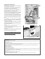
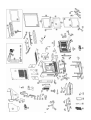
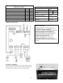
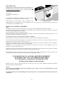
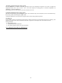
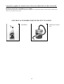
Specifications
PELLBOX SCF
PELLBOX SCF SPECIFICATIONS
INDEX
Miscellaneous and safety information
Operating principle and fuel notes
Exploded view with spare part code numbers
Specifications and wiring diagram
Loading pellets
Dimensions and distances between holes
Assembly and installation (TAC)
Interface
Operation
Low fuel warning
Advice in the event of problems
Servicing: routine, weekly and annual (TAC)
Optional extras
Check list
p. 2
p. 3
p. 4
p. 6
p. 6
p. 7
p. 8
p. 12
p. 12
p. 15
p. 16
p. 18
p. 19
p. 20
Dear Sir or Madam,
thank you for choosing our Pellbox SCF.
Before using your insert, please read this booklet carefully: it explains how to get the most from all its features in complete safety.
Please remember that the 1st ignition must be carried out by a TAC (authorized technical assistance centre), which verifies the
installation and completes the guarantee.
The manufacturer cannot be held liable for any damage which may derive from using the insert after incorrect installation, incorrect
maintenance or misuse.
SAFETY INFORMATION
• The PELLBOX SCF insert is designed to heat the room it is installed in by radiation and by air movement from the front grilles. It
may also heat an adjoining room by air movement from an outlet found on the right side panel. The heat is generated by automatic
pellet combustion in the firebox.
• The only risks which may derive from use of the insert are linked with non-compliance with the installation instructions, direct
contact with live electrical parts (inside) or with the fire or hot parts (glass, pipes and hot air outlet), and the introduction of foreign
substances. Only use pellets as fuel in the firebox.
• If components fail, the insert is fitted with safety devices which shut it down. This must be allowed to happen without interference.
• For correct operation, the insert must be installed in compliance with the instructions on page 8 and the door must not be opened
during operation: combustion is managed automatically so no manual operations are needed.
• Never put foreign substances in the firebox or hopper.
• Do not use flammable products to clean the smoke ducts.
• Firebox and hopper components must only be cleaned using a vacuum cleaner.
• The glass must be cleaned when COLD with a special product (e.g. GlassKamin) and cloth. Do not clean when hot.
• Make sure the insert is installed and ignited by a qualified TAC (technical assistance centre), which must also complete the
guarantee and take responsibility for correct installation.
• During insert operation, the outlet pipes and door reach high temperatures.
• Do not keep objects that are not able to withstand heat in the immediate vicinity of the insert.
• NEVER use liquid fuels to light the insert or rekindle embers.
• Do not block ventilation openings in the room where the insert is installed or air inlets in the insert itself.
• Do not get the insert wet, and do not put wet hands near electrical parts.
• Do not fit reducers on the smoke outlet pipes.
• The insert must be installed in a suitable place as regards fire safety, and provided with all the facilities (power supply and outlets)
it requires for correct safe operation.
2
OPERATING PRINCIPLE
PELLBOX SCF is a pellet-fired insert that manages
pellet combustion electronically.
The fuel (pellets) is taken from the storage hopper (A)
and delivered to the combustion chamber (D) by a
screw feeder (B) driven by a gearmotor (C).
The pellets are ignited by hot air produced by a
heating element (E) which is drawn into the
combustion chamber by a centrifugal fan (F).
The combustion smoke produced is drawn out of the
firebox by the same centrifugal fan (F), and expelled
from the nozzle (G) at the bottom rear of the insert.
Air is blown into the hollow space at the back of the
firebox by a fan (H), where it is heated before coming
out into the room from the front grille (I) and into an
adjoining room through appropriate piping (fig. along
side).
The
amount
of
fuel
and
the
smoke
extraction/combustion air supply are controlled by an
electronic circuit board (L) in order to achieve highly
efficient fuel consumption.
A display-control panel (M) is fitted on the front
under the door which allows all the operating stages to
be managed and displayed.
The same steps can be managed using the remote
control.
The pellet hopper is at the top of the insert.
The hopper is filled through a drawer (N) found at the
front above the hopper itself.
The internal structure of the insert is completely made
of cast iron.
Use the cold grip provided (component 44 in the
exploded view) to open the insert door.
–
Fit the two air circulation grilles (36 x 9 cm)
provided on the front and/or right side of the
fireplace (looking from the front).
Illustrative picture
NOTES on fuel.
Pellbox SCF is designed to burn pellets.
Pellets are small 6 mm diameter (approx.) fuel cylinders made from sawdust pressed at high pressure without adhesives or other
foreign material.
They are sold in 15 kg bags.
In order NOT to jeopardize insert operation, do NOT burn other substances. The use of other materials (including wood), which
can be detected by laboratory analyses, invalidates the guarantee.
EdilKamin has designed, tested and programmed its products to perform best with pellets with the following characteristics:
diameter: 6 millimetres
maximum length: 40 mm
maximum moisture content: 8%
heat output: 4300 kcal/kg (at least)
If pellets with different characteristics are used, the insert will need recalibrating (similar to the initial calibration carried out by
the TAC - technical assistance centre - upon first ignition).
Use of unsuitable pellets may lead to: a decrease in efficiency; operating anomalies; stoppages due to clogging, dirty glass,
unburnt fuel, etc.
Pellets may be simply analysed just by looking at them.
Good: smooth, regular lengths, not very dusty.
Poor-quality: with horizontal and vertical splits, a lot of dust, highly variable lengths and mixed with foreign matter.
3
4
5
TECHNICAL AND HEATING
SPECIFICATIONS
Hopper capacity
Efficiency
Available power (min/max)
Time between refuellings (min/max)
Fuel consumption (min/max)
Heatable room dimensions (min/max)
Weight
Smoke duct diameter (female)
Air intake duct diameter (male)
25
90
3/10
11/35
0.7/2.2
70/250
150
80
40
ELECTRICAL SPECIFICATIONS
kg
%
kW
hours
kg/h
m3
kg
mm
mm
Power supply
Average power consumption
Power consumption during
ignition
Remote control frequency
(supplied as standard)
Protection on mains power
supply
Electronic circuit board
protection
230 VAC +/- 10%
50 Hz
150
W
400
W
infrared
5 x 20 2 A 250
VAC fuse
5 x 20 2 A 250
VAC fuse
WIRING DIAGRAM
SAFETY DEVICES
THERMOCOUPLE: on the smoke outlet. It
measures the smoke temperature.
It controls the ignition, operating and shutdown
stages according to the parameters set.
AIR FLOW SENSOR: on the intake duct. It
trips when the flow of combustion air is not
correct, therefore causing low pressure
problems in the smoke circuit.
SAFETY THERMOSTAT: it trips if the
temperature inside the stove is too high. It
stops pellet loading, thus causing the stove to
go out.
PELLET LOADING
A convenient front drawer allows easy pellet loading without
having to remove the firebox from its housing, thus making it
absolutely safe in compliance with EN 14785 standards.
6
DIMENSIONS (fig. 1)
Smoke outlet
Hot air outlet
A: rear view
B: front view
C: side view
D: view from above
7
ASSEMBLY AND INSTALLATION (TAC - technical assistance centre)
Refer to the local regulations in the country of use for anything not expressly shown. In Italy, refer to UNI standard
10683/2005, along with any regional or local health authority regulations. If the insert is to be installed in a block of
flats, consult the block administration before installing.
COMPATIBILITY CHECK WITH OTHER DEVICES
The insert must NOT be installed in the same room as extractor fans or type B gas equipment.
ELECTRICAL CONNECTION CHECK (THE PLUG MUST BE IN AN ACCESSIBLE PLACE)
The insert is fitted with an electrical power cord for connection to a 230 V 50 Hz socket, preferably protected with a
thermal-magnetic circuit breaker. Voltage variations of greater than 10% may impair insert operation (fit a suitable
residual current circuit breaker if not already installed). The electrical system must comply with the law; in particular
make sure the earth circuit is in working order. The power supply line must have a suitable cross-section for the
equipment rating.
FIRE SAFETY DISTANCES AND LOCATION
The insert must be level for correct operation.
Check the load-bearing capacity of the floor.
The insert must be installed in compliance with the following safety conditions:
- minimum safety distance at the sides and back from medium-level flammable materials: 40 cm
- easily flammable materials must not be located less than 80 cm from the front of the insert
If it is impossible to comply with the distances given above, technical/building measures must be taken to avoid all fire
risks.
If the smoke outlet pipe is connected to walls made of wood or other flammable materials, it must be insulated with
ceramic fibre or other materials with similar characteristics.
AIR INTAKE
An outside air intake with cross section of at least 80 cm2 must be provided behind the insert to ensure sufficient air for
combustion.
Alternatively the air intake must be located in the room where the insert is installed and two suitable intake grilles must
be provided in the structure built around the insert.
It is advisable to ventilate the inside of the building work around the hood with air input from below, which leaves
through the grilles fitted at the top by convection, thus allowing heat recovery and preventing excessive overheating.
SMOKE OUTLET
The insert must have its own smoke outlet (it must not discharge into flues shared with other devices).
The smoke leaves the insert through the 8 cm diameter pipe on the cover.
The insert smoke outlet must be connected with the outside using suitable steel pipes, without obstructions
The pipe seals must be air-tight. To seal and insulate (if necessary) the pipes, material that withstands up to 300°C must
be used (silicone or high temperature mastic).
The horizontal sections may be up to 2 m long. Up to two bends with maximum curvature of 90° may be included.
If the smoke outlet does not end in a flue, a vertical section with wind guard at the end is essential (refer to UNI
standard 10683/2005). The vertical duct section may be indoor or outdoor. If the smoke duct* is outdoor, it must be
suitably insulated.
If the smoke duct* ends in a flue, the flue must be authorized for solid fuel. If it is more than 150 mm in diameter, it
must be renewed by inserting an internal pipe and sealing the smoke outlet from the brickwork.
All sections of the smoke duct* must be inspectable. If it is fixed, cleaning inspection openings must be provided.
Possible installation layouts are shown in figure 2 (A, B, C and D) on p. 9.
* section of flue duct which connects the insert to the flue or the chimney pot if there is no flue.
8
POSSIBLE INSTALLATION LAYOUTS (fig. 2)
A: internal flue up to roof
B: external brick-built flue
C: internal brick-built flue
D: external double-walled steel flue (for the following installation, the entire flue must have a
well insulated double wall)
*
two air circulation grilles (36 x 9 cm, provided) on the front and/or right side of the
fireplace (looking from the front)
9
LOCATION AND AIR CHANNELLING (fig. 3)
Hot air outlet
in adjacent room
or the same room.
Hot air outlet
from front grille
Outlet for coupling channel to
adjacent room
or the same room.
NB:
FIT ACCESSORY AIR
CIRCULATION GRILLE
(C)
Hot air outlet in adjacent room
or the same room.
A: adjacent room
B: anchor plugs to support insert (must be fixed)
C: air circulation grille
NB: FIT ACCESSORY AIR CIRCULATION GRILLE (C) ON THE FRONT AND/OR
RIGHT SIDE OF THE COVERING
10
CHANNELLING
The insert has an opening on the left side (see location p. 7
DIMENSIONS) to channel hot air into an adjoining room or
the same room as the fireplace using a specific optional kit
(No. 7, cod. n. 290420) consisting of:
• hose clamp
• 3 m long Ø 10 flexible hose
• nozzle
It is important to remember the importance of suitable air tube
insulation to prevent heat dispersion and air cooling.
Illustrative picture
Avoid bends in the tube itself as far as possible. The
channelling must not be plugged to avoid overheating. The air must in any case be released into the room where the
insert is found or into an adjacent room.
NOTES ON COVERING ASSEMBLY
Insert
To decide the exact location of Pellbox, the type of covering it will be completed with must be considered.
The insert must be positioned in a different way according to the model chosen (consult the assembly instructions
provided in the packaging of each covering).
During installation, always check plumb and level.
Fasten the supporting frame provided to the floor, with plugs, in order to prevent possible overturning (see fig. 3, p. 10)
when the firebox door is opened for maintenance.
Coverings and structure around the hood, and their ventilation
Before fitting the covering, make sure the connections, controls and all moving parts work correctly.
This check must be done with the fireplace on and working steadily for a few hours, so that any necessary corrective
operations may be carried out before covering the insert.
Consequently, finishing operations, such as building work around the hood, covering assembly, erection of pilasters,
painting, etc., must only be carried out if the tests are passed.
EdilKamin is in no case liable for costs deriving from the removal of these works or their rebuilding, even if it is
necessary in order to replace faulty parts.
Wooden parts must be protected with fire retardant panels, not come into contact with the insert itself, and be a suitable
distance from it (at least 1 cm so that air may flow and prevent heat build-up).
The structure around the hood may be built of fire retardant panels made of plasterboard or sheets of plaster; air
circulation grilles must be provided as previously described when these are built.
IT IS ESSENTIAL TO ASSURE AIR REPLENISHMENT
WITH THE TWO 36 X 9 CM GRILLES PROVIDED
ON THE FRONT AND/OR ON THE RIGHT SIDE
(looking at the fireplace from the front)
Besides the above, bear in mind the instructions in sections 4.4 and 4.7 of UNI standard 10683/2005 "insulation,
finishes and safety recommendations".
NOTE
If you do not wish to channel hot air into an adjacent room, it must in any case be channelled into the room
where the firebox is installed.
Do NOT channel hot air into the building work around the hood or covering since this would lead to dangerous
overheating.
11
INTERFACE:
DISPLAY-CONTROL PANEL
0/1 : Press for 2 seconds to turn on and off
Press briefly to change power level
(power 1 - power 2 – power 3) or temperature
REMOTE CONTROL (included)
0/1 : to turn on and off
Menu: to access the menu
+/- to increase / decrease
various settings
OPERATION
Before ignition.
1st Ignition: contact your local TAC (technical assistance centre, for information consult www.edilkamin.com, or
phone toll-free number in Italy +39 800014142) to calibrate the insert according to the pellets available and
conditions of use.
The first few times the Insert is ignited there may be a slight smell of paint, which disappears rapidly.
Before ignition, check:
⇒
The insert has been installed correctly (see pages 8-9)
⇒
The power supply.
⇒
the door is closed.
⇒
The combustion chamber is clean.
⇒
The display shows standby (flashing date, power or temperature)
SCREW FEEDER LOADING.
When first used or if the pellet hopper empties completely, press the + and - keys on the remote control together for a
few seconds to fill the screw feeder; LOAD appears on the display when the keys are released.
This must be done before igniting the insert again if it has shut down due to running out of pellets.
It is normal for a few pellets to be left in the hopper, which the screw feeder is not able to pick up.
INSTRUCTIONS FOR USE 14
IGNITION
Automatic ignition
When the insert is on standby, press the 0/1 key (on the display-control panel or remote control) for 2 seconds to start
up the ignition procedure. The word Start appears on the display along with a countdown in seconds (1020). The
ignition procedure does not take a preset time: it is automatically shortened if the electronics detect that certain tests are
passed). The flame appears after about five minutes.
Manual ignition
At temperatures of less than 3°C (too low for the heating element to glow) or if the heating element is temporarily out
of order, a firelighter may be used for ignition.
Put a piece of well lit firelighter in the combustion chamber, close the door and press 0/1 on the display-control panel or
remote control.
OPERATING MODES
Power adjustment / Manual operation using the display-control panel
With the insert working, press the 0/1 key on the display-control panel. The word POWER appears on the display along
with the power level the insert is running at. It is possible to increase the power by pressing the 0/1 key repeatedly (from
POWER 1 to POWER 3).
Ventilation is adjusted automatically according to the power chosen.
Power adjustment / Manual operation using the remote control
With the insert working, press the Menu key on the remote control once. The word POWER appears on the display
along with the power level the insert is running at. It is possible to increase or decrease the power by pressing the + or keys (from POWER 1 to POWER 3).
12
Automatic operation using the remote control
Press the Menu key to switch to automatic operation and set the temperature required in the room (to adjust the
temperature from 5°C to 35°C use the + and -). The insert adjusts its working power to reach the temperature set
(POWER 3 or maintain POWER 1).
If the temperature set is lower than in the room, the insert runs at P1.
Ventilation adjustment using remote control
With the insert operating, press the menu key again. The ventilation may now be adjusted (9 levels associated three by
three to the power levels) using the + and - keys.
Ventilation adjustment is only possible using the remote control during manual operation.
Switching off
Hold the 0/1 key down on the display-control panel or remote control for two seconds while the insert is operating. The
shutdown procedure starts and a countdown from 600 to 0 appears on the display (for a total of 600 seconds).
During shutdown:
• Pellet loading ceases.
• Ventilation turns up to maximum
• The smoke expulsion motor turns up to maximum.
Never unplug the insert while it is shutting down.
13
OPERATIONS WHICH CAN ONLY BE CARRIED OUT USING THE REMOTE
CONTROL
Clock adjustment
Hold the menu key down for two seconds to access the clock menu. and set the internal clock on the electronic circuit
board.
Press the menu key repeatedly to display and set the following parameters in the order shown:
day, month, year, hour, minutes, and day of the week.
Once done, "Save??" appears on the display. Make sure the changes made are correct and confirm by pressing the
menu key (the word "Saved" then appears).
INSTRUCTIONS FOR USE 16
Weekly time programmer
Press the menu key on the remote control for two seconds to access the time setting function and press the + key to
access weekly time programming: the message "Program on/off" appears on the display.
The insert may be programmed to come on and switch off automatically up to three times a day on each day of the
week.
Confirm this by pressing the Menu key. One of the following possibilities appears:
NO PROGRAM (not programmed)
DAILY PROGRAM (programmed to do the same thing every day)
WEEKLY PROGRAM (programmed differently for each day)
You can go from one to another using the + and - keys.
Confirm the "DAILY PROGRAM" option with the menu key to choose the number of programs (on/off) per day.
If you confirm "DAILY PROGRAM", the program(s) set will be the same every day of the week.
Press the + key repeatedly to display:
- No program
- 1st program (one ON and one OFF per day), 2nd program (ditto), then 3rd program (ditto)
Using the - key displays the items in reverse order.
If 1st program is selected, the ON time is displayed.
The display shows: 1 ON hour 10,30; use the +/ - keys to change the hour and press the menu key to confirm.
The display shows: 1 ON minutes 10,30; use the +/ - keys to change the minutes and press the menu key to confirm.
Proceed in the same way to program the OFF time and the other program times.
When Save?? appears on the display, confirm the changes by pressing the menu key.
After confirming "WEEKLY PROGRAM", choose the day the program applies to:
1 Mon, 2 Tue, 3 Wed, 4 Thu, 5 Fri, 6 Sat and 7 Sun
Once the day has been selected using the + and - keys and confirmed with the menu key, continue in the same way as
for the "DAILY PROGRAM". Choose the number of programs and the times for each day of the week.
If you make a mistake while programming, you can quit by pressing the 0/1 key: the display shows "Saved".
The operations described here (power/temperature and ventilation adjustment, clock adjustment, programming on/off
times, changing pellet load, cold tests and parameter adjustment) may only be carried out using the REMOTE
CONTROL.
To use the remote control, point it towards the insert. A beep confirms command reception, which is also confirmed
by the command taking place.
The most frequent cause of remote control malfunction is flat batteries. Replace and dispose of used batteries
suitably.
Change pellet load
Press the menu key on the remote control for two seconds and scroll through the items using the +/- keys until "ADJPELLET" appears on the display.
Confirm this item by pressing the menu key. The pellet load setting appears. Decreasing the setting decreases the pellet
load; increasing the setting increases the pellet load. This function may be useful if the type of pellet the insert has been
calibrated for is changed, thus making load adjustment necessary.
If adjusting this setting is not sufficient, contact the TAC (technical assistance centre) for a new operating setup.
14
Note on flame variability
Any variations in the state of the flame depend on the type of pellet used, the normal variability associated with solid
fuels and the periodic automatic combustion chamber cleaning (which does NOT replace the essential cold vacuumcleaning by the user before ignition).
LOW FUEL WARNING
The Pellbox SCF insert has an electronic function which detects the amount of pellets left in the hopper.
The detection system integrated into the electronic circuit board monitors how many hours and kilos are left until the
pellets run out.
For correct system operation, it is important that the following procedure is followed during the first ignition (by a
TAC).
First ignition/testing (by a TAC)
The insert must be installed pursuant to point 3.21 of UNI standard 10683.
This standard describes the operations to be carried out on the field in order to check correct system operation.
Low system pellets
Before starting the system up, it is necessary to fill the hopper with a bag of pellets and use the PELLBOX until the
loaded fuel is used up.
This is necessary in order to run the system in briefly.
After this, it is possible to fill the hopper completely and start the PELLBOX up.
During operation, the words “Low Fuel” flash on the display when it is possible to load a whole new 15 kg bag of
pellets.
After pouring the bag in, it is necessary to add the 15 kilos to the memory.
To do this, proceed as follows:
1.
2.
3.
press the “Menu” key (for about 3-4 seconds) until the word “Clock” appears.
press the “+” key until the “Low pellet level” message disappears.
press the “Menu” key to bring up the next screen, than use the “+” key to bring the figure (*) up to the number
of kilos loaded (15 kg in the case of this example).
PELLETS
KG 07 + 15*
kilos left in the hopper
4.
5.
kilos to load
press the “Menu” key to confirm
press the “0/1” key to quit.
by following the steps described above, the words “Low Fuel” will flash on the display again when the system has
burnt another 15 kg of pellets.
When this occurs, the operation should be repeated from point 1 to point 5.
15
ADVICE IN THE EVENT OF PROBLEMS
DISPLAY-CONTROL PANEL/SAFETY DEVICES
PROBLEM
CAUSE
display-control panel off
no mains voltage
remote control not working
outlet air not hot
no flame appears (remember that it
only appears 5 minutes after
pressing the On/Off key)
ignition failure
The ignition/off does not start at the
time required
excessive distance from insert
remote control battery flat
too much soot in heat exchanger
the screw feeder has not been filled
build up of unburnt material in
combustion chamber
Incorrect setting:
clock
programme enabling
programme enabling for the day
SOLUTIONS
make sure the power cord is
connected
check the fuse (on the power socket)
move nearer to insert
check battery and replace if necessary
clean heat exchanger from inside the
firebox
Fill screw feeder (see ignition
paragraph)
clean combustion chamber
Check according to instructions
The chimney pots and smoke ducts connected to solid fuel devices must be cleaned once a year (check whether there are
regulations on the subject in the country of installation). If inspection and regular cleaning are not carried out, the
probability of a chimney pot fire increases. In the event of a chimney pot fire, proceed as follows:
do not use water to extinguish;
empty the pellet hopper;
contact specialist staff after the accident before starting up again.
C
POSSIBLE CAUSES OF SHUTDOWN
Information that may appear on the display in the event of shutdown:
1)
2)
3)
4)
5)
6)
7)
No depression: shutdown due to low pressure
No expulsion: shutdown due to a fault detected by the smoke exhaust motor sensor
No fire: shutdown due to a drop in smoke temperature
No start: shutdown due to incorrect smoke temperature during ignition
Power failure: shutdown due to power failure
Termoc broken: shutdown due to thermocouple failure or disconnection
Over temp: shutdown when the maximum smoke temperature set is exceeded.
The message is displayed until the 0/1 key on the panel is pressed
Do not restart the insert until the problem has been looked into and the cause removed.
To start the insert up again after a shutdown, let the shutdown procedure end
(600 seconds marked by a beep) then press the 0/1 key.
Never unplug the insert while it is shutting down due to problems.
It is important to report what the panel says to the TAC (technical assistance centre).
NOTE
After 2500 kg of pellets are consumed, the display shows the word "service”
The insert works, but you should contact an authorized TAC for special maintenance.
16
ADVICE IN THE EVENT OF PROBLEMS
1) No Depression (this trips if the flow sensor detects insufficient combustion air flow).
The flow may be insufficient because the door is open, the door does not close properly (e.g. bad seal), there is an air
intake or smoke extraction problem, the combustion chamber is clogged, or the flow sensor is dirty (clean with dry air)
Check flow sensor threshold (in parameters).
The low pressure alarm may also occur during ignition.
2) No Expulsion (this trips if the smoke extraction speed sensor detects a fault)
- Check smoke extractor operation (speed sensor connection)
- Make sure the smoke duct is clean
3) No fire (this trips if the thermocouple detects a smoke temperature lower than the value set, which it interprets as the
absence of flames)
There may be no flames because
- there are no pellets
- too many pellets have smothered the flames
the maximum temperature thermostat has tripped (this is very unusual since it would only trip if there was excessive
smoke temperature)
4) No start (this trips if no flames appear or the start-up temperature is not reached within a maximum of 15 minutes).
There are two distinct cases:
The flame does NOT appear
Check:
- combustion chamber position and cleanliness
- if the heating element is working
- room temperature (if lower than 3°C) and damp. Try to
light with a firelighter.
Flames appear, but after the word "Start", the
message "Start Failed" appears
Check:
- if the thermocouple is working
- start-up temperature setting in the parameters.
5) Power failure
Check the electrical connection and for voltage drops.
6) Termoc broken (this trips if the thermocouple fails or is disconnected)
Check connection between the thermocouple and the circuit board: check operation with cold tests.
7) Over temp (shutdown due to excessive smoke temperature)
Excessive smoke temperature may be caused by: the type of pellet, smoke extraction fault, blocked smoke duct,
incorrect installation, or gearmotor "drift".
17
SERVICING
Regular maintenance is essential for good insert operation
Before carrying out any maintenance, disconnect the device from the mains power supply.
DAILY CLEANING
Clean with a vacuum cleaner. The whole process takes a few minutes a day.
USING A VACUUM CLEANER, when the insert is cold:
- Vacuum-clean the door, the hearth and the space around the combustion chamber where the ash falls.
- Remove combustion chamber, clean it with the small metal box, and unblock any blocked holes on all sides.
Vacuum-clean the combustion chamber compartment and the edges which touch the housing, and replace the
combustion chamber.
- If necessary clean the glass (when cold).
NEVER VACUUM-CLEAN HOT ASH, since it may damage the vacuum cleaner.
WEEKLY CLEANING
Pellbox SCF has two spy holes on the hearth “A” and two on the ceiling of the firebox “B" which allow easy effective
access for cleaning the smoke duct.
- essential smoke duct cleaning
“A”
“B”
- Empty the hopper and vacuum-clean the bottom if the insert is left unused. Do this in any case once a fortnight.
EVERY SEASON (by the TAC - technical assistance centre)
- After 2500 kg of pellets are consumed, the display shows the word “service”, which means maintenance is needed.
- General internal and external cleaning
- Carefully clean heat exchange pipes
- Carefully clean and descale combustion chamber and corresponding compartment
- Clean fan and mechanically inspect play and fastenings
- Clean smoke duct (replace gasket on smoke outlet pipe)
- Clean smoke extractor fan compartment and flow sensor, and check thermocouple
- Clean, inspect and descale ignition heating element compartment and change the heating element itself if necessary
- Clean/check display-control panel
- Visually inspect electric cables, connections and power cord
- Clean pellet hopper and check screw feeder-gearmotor assembly play
- Change door seal
- Test screw feeder loading, ignition, operation for ten minutes and shutdown
If the insert is used frequently, it is advisable to clean the smoke duct every 3 months.
18
FAILURE TO CARRY OUT MAINTENANCE LEADS TO FORFEITURE OF THE GUARANTEE.
OPTIONAL EXTRAS:
REMOTE IGNITION BY TELEPHONE (cod. n. 281900)
The insert may be turned on remotely by phone by having the TAC (technical assistance centre) connect a dialler to the
electronic circuit board (AUX port)
SUITABLE ACCESSORIES FOR EXCELLENT CLEANING
PIPPO ash vacuum
bin
GlassKamin
19
CHECK LIST
Read the entire specifications before using this list
Installation and setup
¾ Installation carried out by an authorized TAC which has issued the guarantee and maintenance
booklet
¾ Room ventilation
¾ The smoke duct/flue only receives smoke from the insert
¾ The smoke duct has:
¾ no more than 2 bends;
¾ a horizontal section of no more than 2 metres.
¾ chimney pot beyond the reflux area
¾ the outlet pipes are made of a suitable material (stainless steel is recommended)
¾ where pipes cross any flammable materials (e.g. wood) all precautions have been taken to avoid fire
Presence of air circulation grilles (36 x 9 cm) provided
Use
¾ The pellets used are good quality and not damp
¾ The combustion chamber and ash pan are clean and have been placed correctly
¾ Glass cleaning always takes place when glass is cool.
¾ The firebox smoke closure components (No. 14 and No. 15 in the exploded view) are fitted
correctly.
¾ The door is closed well.
¾ The combustion chamber is correctly inserted in its compartment
REMEMBER TO VACUUM-CLEAN THE COMBUSTION CHAMBER BEFORE EACH
IGNITION
If ignition fails, do NOT repeat ignition before emptying the combustion chamber
EDILKAMIN S.p.A.
Via Mascagni, 7 - 20020 LAINATE (MI) - Italy
Tel. +39 02937621 – Fax +39 0293762400
www.edilkamin.com - [email protected]
EdilKamin S.p.A. reserves the right to modify parts of this manual without prior notice
20
cod. n: 288890
2.06-07/A