1
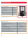
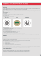
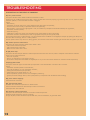
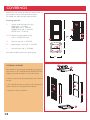
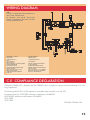
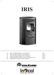
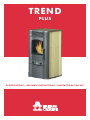
TREND
PLUS
SPECIFICATIONS - ASSEMBLY INSTRUCTIONS - INSTRUCTIONS FOR USE
Dear Madam, Dear Sir,
thank you for choosing our "TREND" stove.
Before using your stove, please read this booklet carefully: it explains how to get the most from all its features in complete safety. For any further clarification or requirements, phone us on: 02.93762333
ITALIANA CAMINI S.R.L.
INDICE
Safety information
Description and operating principle (structure and technical data).
Assembly and installation (TAC)
Interface
Operation
Before ignition (filling the screw feeder)
Notes on fuel
Ignition
Operating modes: manual / automatic
Switching off
Safety devices
Advice in the event of problems.
Servicing: routine and annual (TAC)
Remote ignition by phone and timer connection
Covering assembly
Installation accessories
p. 2
p. 3
p. 7
p. 9
p. 9
p. 9
p. 3
p. 10
p. 10
p. 10
p. 11
p. 11
p. 13
p. 13
p. 14
p. 16
SAFETY INFORMATION
The stove is designed to heat the room it is installed in by radiation and by air movement from the front grilles. The heat is generated by
automatic pellet combustion in the firebox.
The only risks which may derive from use of the stove are linked with non-compliance with the installation instructions, direct contact with live
electrical parts (inside) or with the fire or hot parts (glass, pipes and hot air outlet), and the introduction of foreign substances. If components
fail, the stove is fitted with safety devices which turn it off. This must be allowed to happen without interference.
For correct operation, the stove must be installed in compliance with the instructions on page 6 and the door must not be opened during
operation:
combustion is managed automatically so no manual operations are needed.
Never put foreign substances in the firebox or hopper.
Do not use flammable products to clean the smoke duct. Firebox and hopper components must only be cleaned using a vacuum cleaner.
The glass must be cleaned when COLD with a special product (e.g. GlassKamin) and cloth. Do not clean when hot.
Read this manual before using the stove.
Make sure the stove is ignited by a qualified TAC (technical assistance centre), which must also complete the guarantee and take responsibility
for correct installation.
During stove operation, the outlet pipes and door reach high temperatures: let children know about this risk.
Do not keep objects which are not able to withstand heat in the immediate vicinity of the stove.
NEVER use liquid fuels to light the stove or rekindle the embers.
Do not block ventilation openings in the room where the stove is installed.
Do not wet the stove, and do not put wet hands near electrical parts.
Do not remove hot embers with a vacuum cleaner.
Do not fit reducers on the smoke outlet pipes.
Parts highlighted in orange are for TACs (technical assistance centres) only.
OPERATING FEATURES
DESCRIPTION
The TREND stove is pellet-fired with electronically controlled combustion. Pellets are small cylinders of pressed wood.
The internal structure of the stove is completely made of cast iron.
Smoke is vented from the back, at the base, by an extraction motor which expels it horizontally.
The pellet hopper is at the top of the stove.
The hopper is filled through a lid found at the back of the top.
The external covering consists of ollite tiles or ceramic tiles available in the following colours: sand, terracotta and winered.
OPERATING PRINCIPLE
I
The fuel (pellets) is taken from the storage hopper (A) and delivered to the combustion chamber (D) by a screw feeder (B) driven by a gearmotor (C).
A
The pellets are ignited by hot air produced by a heating element (E) which is drawn into the combustion chamber by a
centrifugal fan (M).
The combustion smoke produced is drawn out of the firebox
by the same centrifugal fan (M), and expelled from the nozzle
(F) at the bottom rear of the stove.
B
Air is blown into the hollow space at the back of the firebox by
two fans (G), where it is heated before coming out into the
room from the front grille (I).
The amount of fuel and the smoke extraction/combustion air
supply are controlled by an electronic circuit board (N) in
order to achieve highly efficient fuel consumption.
There is a display-control panel (L) and two knobs on the front
panel under the door which allow all operating stages to be
managed and displayed. The same functions may also be
managed by remote control (optional).
D
L
C
E
F
M
N
G
NOTES on fuel.
The TREND pellet stove is designed and programmed to burn pellets.
Pellets are small 6 mm diameter (approx.) fuel cylinders made from sawdust and ground waste wood pressed at high pressure without
adhesives or other foreign material.
In order NOT to jeopardize stove operation, do NOT burn other substances.
The use of other materials (including wood), which can be detected by laboratory analyses, invalidates the guarantee.
EdilKamin has designed, tested and programmed its stoves to perform best with pellets with the following characteristics:
diameter: 6 - 7 millimetres, maximum length: 40 mm, maximum moisture content: 8 %, heat output: 4300 kcal/kg (at least)
If pellets with different characteristics are used, the stove will need recalibrating (similar to the initial calibration carried out by the
TAC - technical assistance centre - upon 1st ignition).
Use of unsuitable pellets may lead to: a decrease in efficiency; operating anomalies; stoppages due to clogging, dirty glass, unburnt
fuel, etc.
Pellets may be simply analysed just by looking at them.
Good: smooth, regular lengths, not very dusty.
Poor-quality: with horizontal and vertical splits, a lot of dust, highly variable lengths and mixed with foreign matter.
3
EXPLODED VIEW OF STRUCTURE
N.
1
2
3
4
5
6
7
8
9
10
11
12
13
15
16
18
21
22
23
24
25
26
27
4
Description
ANTI-VIBRATION MOUNT 30 x 20 x 8/70
BASE
LOWER WALL SUPPORT BAR
INSULATING GASKET
ASH GUARD BAR
CAST IRON FRAME
CAST IRON COMBUSTION CHAMBER
HANDLE HINGE BUSH
RIGHT WALL OF COMBUSTION CHAMBER SUPPORT
FRONT RIGHT COVERING SUPPORT
FLANC LATERAL CERAMIQUE (1 pièce)
TERRE CUITE
SABLE
BORDEAUX
PIERRE OLLAIRE
REAR/FRONT LEFT ALUMINIUM BAR
UPPER WALL SUPPORT BAR
CAST IRON TOP
PELLET HOPPER COVER
RUBBER BUNG
INTERNAL AIR BAFFLE
VENTILATION AIR CONVEYOR
CONVEYOR CLOSING BAR
PROTECTION GRILLE
RUBBER TUBE FOR PELLET GRILLE
REAR PELLET HOPPER WALL
PELLET HOPPER
Code
Nb pièces
249970
4
252480
1
247400
2
249190
2
249120
1
249330
1
248710
1
254110
1
247270
1
254500
1
264550
253150
264540
278140
6
6
6
6
253140
3
247250
2
252530
1
252540
1
234420
1
247300
1
247410
1
354740
1
257480
1
199040
1
253630
1
253580
1
28
SCREW FEEDER HALF COVER
247330
1
29
UPPER LOADER COVER
247480
1
30
120°C THERMOSTAT WITH AUTOMATIC RESET
255360
1
31
LOADER BODY
249960
1
32
CERAMIC PAPER GASKET FOR PELLET OUTLET
247370
1
33
TEFLON COATED LOADER BUSH
249010
2
34
LOADER SHAFT
249343
1
35
CERAMIC PAPER GASKET FOR LOADER
247380
1
36
LOWER SHAFT LOCKING FLANGE
247320
1
37
GEARMOTOR LOCKING BUSH
232580
1
38
1.5 rpm MK GEARMOTOR
230560
1
39
STAINLESS STEEL SMOKE PIPE
250300
1
40
TYPE "J" THERMOCOUPLE
255370
1
41
IGNITION AND EXHAUST PIPE
249350
1
42
300 W CARTRIDGE
248510
1
43
CARTRIDGE FASTENING BUSH
247350
1
44
FLOW SENSOR
232770
1
45
ROOM TEMPERATURE DETECTOR
255380
1
46
RUBBER ROOM TEMPERATURE SENSOR HOLDER
266650
1
47
MAINS POWER SOCKET WITH SWITCH
235210
1
48
POWER SOCKET FASTENING BAR
254213
1
49
REAR PANEL
253590
1
50
LEFT WALL OF COMBUSTION CHAMBER SUPPORT
247390
1
52
ANTI-VIBRATION SPACERS
285240
2
53
RUBBER ANTIVIBRATION MOUNTS
284930
4
54
TANGENTIAL FAN
284870
1
55
SMOKE EXHAUST MOTOR FASTENING FLANGE
250320
1
56
SMOKE EXTRACTOR FAN
215130
1
57
PAPER SEAL FOR SMOKE EXHAUST MOTOR
201010
1
58
ELECTRONIC CIRCUIT BOARD FASTENING BRACKET
248120
1
59
ELECTRONIC CIRCUIT BOARD FOR WEEKLY PROGRAMMING
263330
1
60
INTERNAL ELECTRIC CABLE KIT
250050
1
61
MAINS POWER SUPPLY CABLE
230210
1
62
FRONT CAST IRON AIR OUTLET GRILLE
252490
1
63
10 DIAM. GASKET
425780
1,5 mt
64
UPPER GLASS HOLDER
354560
1
65
CAST IRON DOOR FRAME
252500
1
66
DOOR HANDLE
254640
1
67
LOWER DOOR FASTENING PIN
248380
1
68
ADHESIVE 8 X 2 BLACK FIBRE SEAL
173050
0,28 mt x 2
69
285 X 308 X 4 GLASS
247450
1
70
LOWER GLASS HOLDER
247280
1
71
RUBBER SPACERS
216510
2
72
CONTROL PANEL
252510
1
73
ADJUSTMENT KNOBS
249430
2
74
DISPLAY-CONTROL PANEL SUPPORT
249140
1
75
10 X 2 ADHESIVE GASKET
425810
0,9 mt
76
COMBUSTION CHAMBER INSPECTION FLANGE
247310
1
77
10 DIAM/6.1 X 10 BUSH
252550
4
78
COMBUSTION CHAMBER INSPECTION PANEL
249130
1
79
LOWER CAST IRON DOOR
252520
1
80
WEEKLY PROGRAMMING DISPLAY-CONTROL SWITCH
263320
1
81
GLOVE
6630
1
82
SCRAPER
196500
1
83
REMOTE CONTROL (optional)
254160
1
The code numbers beside the components are for use when ordering.
5
SPECIFICATIONS
TECHNICAL CHARACTERISTICS *
Hopper capacity
14 kg
Average efficiency
80%
Available power (min / max)
2 / 5.6 kW
Time between refuellings (min / max)
10 / 28 h
Fuel consumption (pellets)
0.5 / 1.4 kg/h
Weight
130 kg
Heatable room dimensions
60/150 m
Independent smoke outlet diameter (A female)
80 mm
Independent external air intake duct diameter (B male)
40 mm
B
3
A
* The data shown was obtained using pellets compliant
with the characteristics listed on p. 3.
** electric socket
ELECTRICAL CHARACTERISTICS:
Power supply:
230 VAC +/- 10% 50 Hz
Maximum power consumption (normal operation):
250 W
Power consumption during ignition (max 9 min.)
300 W
Remote control frequency:
infrared
Remote control batteries:
12 V size 23 A
Protection on mains power supply:**
5 x 20 2A 250 VAC fuse
Electronic control circuit board protection:
5 x 20 2A 250 VAC fuse
Thermocouple flame detection safety system
yes
Excessive stove body temperature safety system with bimetallic thermostat
yes
Pellet supply adjustment with three power levels
yes
Room air ventilation min-max adjustment for every power
yes
Internal semiconductor probe for regulating room temperature
yes
6
INSTALLATION INSTRUCTIONS
ASSEMBLY AND INSTALLATION (TAC - technical assistance centre)
For anything not expressly mentioned, refer to Italian standard UNI 10683/2005, along with any regional or local health authority regulations. If the stove is to be installed in a block of flats, consult the block administration before installing.
COMPATIBILITY CHECK WITH OTHER DEVICES
According to Italian standard UNI 10683/98, the stove must NOT be installed in the same room as extractor fans or type A or B gas
equipment.
ELECTRICAL CONNECTION CHECK (THE PLUG MUST BE IN AN ACCESSIBLE PLACE)
The stove is fitted with an electrical power cord for connection to a 230 V 50 Hz socket, preferably protected with a thermal-magnetic
circuit breaker. The electrical system must comply with the law.
FIRE SAFETY DISTANCES AND LOCATION (fig. 4)
N.B.: FOR CORRECT OPERATION THE STOVE MUST BE LEVEL.
The stove must be installed in compliance with the following safety conditions:
- minimum safety distance at the sides and back from medium-level flammable materials: 40 cm;
- easily flammable materials must not be located less than 80 cm from the front of the stove;
- if the stove is installed on a flammable floor, a sheet of heat insulating material must be placed between the stove and the floor, which
protrudes by at least 20 cm at the sides and 40 cm at the front.
If it is impossible to comply with the distances given above, technical/building measures must be taken to avoid all fire risks.
Objects made of flammable materials must not be placed on the stove or at less than the safety distance from it.
If the smoke outlet pipe is connected to walls made of wood or other flammable materials, it must be insulated with ceramic fibre or
other materials with similar characteristics.
INSTALLATION
AIR INTAKE
The room where the stove is located must have an air intake with cross section of at least 80 cm2 to ensure replenishment of the air
consumed by combustion.
Alternatively, the stove air may be taken directly from outside through a 4 cm steel extension of the pipe. In this case, there may be condensation problems and it is necessary to protect the air intake with a grille, which must have a free section of at least 12 cm2. The
pipe must be less than 1 metre long and have no bends.
It must end with section at 90° facing downwards or be fitted with a wind guard.
SMOKE OUTLET
The stove must have its own smoke outlet (it must not discharge into flues shared with other devices).
The smoke leaves the stove through the 8 cm diameter pipe at the back.
A T-section with condensation trap and bleeder must be fitted.
It must be connected with the outside using black painted or steel pipes (resistant to 450°C), without obstructions.
The pipe seals must be air-tight. To seal and insulate (if necessary) the pipes, material that withstands up to 300°C must be used (silicone or high temperature mastic).
The horizontal sections may be up to 2 m long.
Up to two 90° bends may be included.
If the smoke outlet does not end in a flue, a suitably fixed vertical section (at least 1.5 m long unless clearly unadvisable for safety reasons) with wind guard at the end is essential. The vertical duct section may be indoor or outdoor. A workmanlike installation entails a
roof outlet (Italian standard UNI 10683, point 4.2.3).
If the smoke duct is outdoor it must be insulated.
If the smoke duct ends in a flue, the flue must be authorized for solid fuel. If it is more than 150 mm in diameter, it must be renewed
by inserting an internal pipe and sealing the smoke outlet from the brickwork.
All sections of the smoke duct must be inspectable. If it is fixed, cleaning inspection openings must be provided
Possible installations are shown in figures 1, 2 and 3 on p. 8.
7
ISTRUZIONI PER L’ INSTALLAZIONE
fig. 2
fig. 1
smoke
brick-built
flue
1.5 m minimum h
80
A
combustion air
taken from room
fig. 3
B
40
combustion air
taken from
outside
A
80
40
B
air intake from
outside to
room (minimum internal
section:
80 cm2)
Distance from flammable material
Floor protection
80
40
1.5 m minimum h
8
fig. 4
INSTALLATION INSTRUCTIONS
INTERFACE
Left knob (SX)
For power adjustment during manual operation and temperature adjustment during automatic operation. The operating mode may be set
using the A/M key on the central panel. The display shows the power or temperature set.
Right knob (DX)
For room air flow adjustment, which in any case cannot be set lower than the minimum necessary to ensure cooling of the internal stove
parts.
Panel On/Off key
To turn the stove on or off.
Panel A/M key
For switching the stove from manual to automatic operation and vice versa.
Panel "hourglass" key
For setting the programmed on/off times.
left knob
panel
right knob
Display unit messages:
Ac: Ignition stage (flame appearance).
Ar: second Ignition stage (flame stabilizing) before the operating stage.
Off: shutdown stage (10 minutes).
P1 or P2 or P3: power level set.
8-29: temperature set for automatic operation.
H1...H7: stoppage problem identification number (see p. 11).
Pu: automatic combustion chamber cleaning under way.
nn: motor stopping; wait a few tens of seconds before entering other commands.
When the stove is on standby, the display shows the power level or temperature at which it will start up again, and the time (flashing).
OPERATION
Make sure the switch on the electric socket is set to 1
Before ignition.
1st Ignition: contact your local TAC (technical assistance centre, for information phone our toll-free number from Italy) to calibrate the stove
according to the pellets used and conditions of use.
The first few times the stove is ignited there may be a slight smell of paint, which disappears rapidly.
Before ignition, check:
==> The stove has been installed correctly (see pages 7-8 ).
==> The power supply.
==> The door is closed.
==> The combustion chamber is clean.
==> The display shows standby (flashing power or temperature).
Hold the ON/OFF key down for at least two seconds: the stove will automatically start loading pellets to start combustion (the display
shows Ac). No flames appear for the first few minutes. Ac changes into Ar when the flame appears.
SCREW FEEDER LOADING.
If the pellet hopper empties completely, press the On/Off and A/m keys together to fill the screw feeder.
This must be done before igniting the stove again if it has shut down due to running out of pellets.
It is normal for a few pellets to be left in the hopper, which the screw feeder is not able to pick up.
9
INSTRUCTIONS FOR USE
IGNITION
Automatic ignition
Hold the ON/OFF key down for two seconds with the stove on standby to start the ignition procedure. Ac appears on the display for a few
minutes (the ignition procedure does not actually take a preset time: it is automatically shortened if the electronics detect that certain tests
are passed). The flame appears after about five minutes. It is normal for a little smoke to be seen in the combustion chamber before the
flame appears. "Ar" appears on the display until the flame stabilizes.
Manual ignition
At temperatures of less than 3°C (too low for the heating element to glow) or if the heating element is temporarily out of order, a firelighter
may be used for ignition. Put a piece of well lit firelighter in the combustion chamber, close the door and press ON/OFF.
OPERATING MODES (when the stove is working, press the A/m key to switch between modes)
Manual: adjust the working power (from P1 to P3 with the left knob) and the ventilation (with the right knob ).
Automatic: set the temperature which the room is to reach; the stove automatically adjusts the working power to reach it (P3) or maintain it
(P1).
If you set a lower temperature than current room temperature, the stove operates at P1 and consumes the corresponding quantity of pellets.
Note on flame variability
Any variations in the state of the flame depend on the type of pellet used, the normal variability associated with solid fuels and the periodic
automatic combustion chamber cleaning (which does NOT replace the essential cold vacuum-cleaning by the user before ignition).
SWITCHING OFF
Hold the ON/OFF key down for two seconds while the stove is operating. The shutdown procedure starts and the word "off" appears on the
display (for a total of 10 minutes).
During shutdown:
o Pellet loading ceases.
o Ventilation turns up to maximum.
o The smoke expulsion motor turns up to maximum.
Never unplug the stove while it is shutting down.
WEEKLY TIME PROGRAMMER BUILT INTO PANEL
The concept of the weekly time programmer built into the central panel.
It is possible to set 3 ignition programmes:
Pr01 with settable on and off times;
Pr02 with settable on and off times;
Pr03 with settable on and off times.
It is possible to enable one or more of the three settings on each day of the week (day1 = Monday, day2 = Tuesday…day7 = Sunday).
When on standby, the display alternates between showing the ignition mode (P1, P2, P3 or a temperature) and the clock.
Refer to page 9 for each of the buttons to press.
Setting the clock
Press the "hourglass" once. When ESC appears, press On/off(-). When SET appears, press the "hourglass" again. HOUR:MIN appears. It is
now possible to change the setting with the On/off (-) and Am (+) keys. Once the time is set, press the "hourglass" to confirm. The day number then appears (day1 = Monday, day2 = Tuesday…day7 = Sunday). It is now possible to change the day with the On/off (-) and Am (+)
keys. Press the "hourglass" to confirm. When ESC appears, press the "hourglass" again to quit programming.
Enabling programmes
Press the "hourglass" once. When ESC appears, press Am(+). When Pr off appears, press the "hourglass" again. When "off" appears, press
On/off(-) or Am(+) to change it to "on". Press the "hourglass" to confirm. When ESC appears, press the "hourglass" again to quit programming. When the stove is in Pr On mode, it responds to programmed on and off times.
Setting a programme (e.g. Pr01)
Press the "hourglass" once. When ESC appears, press Am(+) repeatedly until Pr01 appears (after Pr On, set as described above).
Confirm with the "hourglass". ON P1 appears followed by the programme 1 ignition time. This time can be changed using the On/off(-) and
Am(+) keys.
Confirm by pressing the "hourglass".
OfP1 appears, followed by the programme 1 off time. This time can be changed using the On/off(-) and Am(+) keys.
Confirm by pressing the "hourglass".
Ofd1 appears (i.e. programme 1 is not enabled for day 1, Monday). To enable it, press Am(+). Ond1 appears, i.e. programme 1 is enabled on Monday.
Press the "hourglass" to move on to the second day, and so on until day7. Press the "hourglass" to quit".
The Pr02 and Pr03 on and off times and the days on which they are enabled can be set in a similar way.
When the programmes are enabled, a green light appears next to the hourglass symbol.
10
DISPLAY-CONTROL PANEL/SAFETY DEVICES
POSSIBLE CAUSES OF SHUTDOWN
If the stove shuts down, the reason is shown on the display.
H1 low pressure alarm: problem connected with air circulation.
H2 Smoke expulsion motor failure.
SF (H3) flame stop.
AF (H4) ignition failed.
H5 power failure stoppage.
H6 thermocouple failure or disconnection.
H7 excessive smoke temperature.
The message is displayed until the ON/OFF key on the panel is pressed after leaving the stove to shut down for ten minutes.
Do not restart the stove until the problem has been looked into and the cause removed.
In the event of problems
To start the stove up again after a shutdown, let the shutdown procedure end (10 minutes marked by a beep) then press the ON/OFF
key.
Never unplug the stove while it is shutting down due to problems.
It is important to report what the panel says to the TAC (technical assistance centre).
SAFETY DEVICES
THERMOCOUPLE:
on the smoke outlet. It measures the smoke temperature.
It controls the ignition, operating and shutdown stages according to the parameters set.
AIR FLOW SENSOR:
on the intake duct. It trips when the flow of combustion air is not correct, therefore causing low pressure problems in the smoke circuit.
It turns the stove off and displays an "H1" alarm if the firebox door is open, the smoke circuit is blocked or the smoke outlet pipe is
blocked.
SAFETY THERMOSTAT:
It trips if the temperature inside the stove is too high.
It stops pellet loading, thus causing the stove to go out.
SUGGESTIONS IN THE EVENT OF PROBLEMS
PROBLEM
POSSIBLE CAUSE
display-control panel off and buttons
no mains voltage
not working
SOLUTIONS
- make sure the power cord is connected
excessive distance from stove
- move nearer to stove
remote control batteries
- check and change if necessary
ignition failure
build up of unburnt material in combustion chamber
- clean combustion chamber
outlet air not hot
too much soot in heat exchanger
- clean the heat exchanger from inside the firebox
no flame appears *
the screw feeder has not been filled
(p. 9)
- fill it
remote control (optional) not working
* Remember that the flame appears about seven minutes later and the ignition stage in any case lasts about a quarter of an hour.
11
TROUBLESHOOTING
SUGGESTIONS IN THE EVENT OF PROBLEMS
H1) Low pressure alarm
This trips if the flow sensor detects insufficient combustion air flow.
The flow may be insufficient because the door is open, the door does not close properly (e.g. bad seal), there is an air intake or smoke
extraction problem, or the combustion chamber is clogged.
Check:
- door closure;
- combustion air intake duct (clean, paying attention to the flow sensor components);
- clean the flow sensor with dry air (like that used for PC keyboards);
- stove location: it must never be right against a wall, as laid down by UNI (Italian Standards Institution) fire regulations;
- combustion chamber position;
- smoke duct (clean);
- installation (if it does not comply with regulations or the smoke outlet has too many bends);
- combustion chamber cleanliness (clean with an appropriate frequency for the type of pellet).
If you suspect the sensor is malfunctioning, carry out cold tests. If the conditions are changed (for example by opening the door) and
the value does not change, there is a sensor problem.
The low pressure alarm may also occur during ignition, since the flow sensor starts monitoring 90 seconds after the ignition cycle starts.
H2) Smoke expulsion motor failure
This trips if the smoke extraction speed sensor detects a fault.
- Check smoke extractor operation.
- Check speed sensor connection.
- Make sure the smoke duct is clean.
SF (H3) flame stop
This trips if the thermocouple detects a smoke temperature lower than the value set, which it interprets as the absence of flames.
There may be no flames because
- there are no pellets;
- there is no combustion air (low pressure alarm);
- the maximum temperature thermostat has tripped (this is very unusual since there would be an excessive smoke temperature).
AF (H4) Ignition failed
This trips if no flames appear and the start-up temperature is not reached within a maximum of 15 minutes.
Check:
- combustion chamber position and cleanliness;
- arrival of combustion air in the combustion chamber;
- heating element/thermocouple operation;
- pellet loading (screw feeder filling on p. 9);
- room temperature (if lower than 3°C use a firelighter) and damp;
- ignition parameter settings: delta T, start-up temperature (in comparison with the detector state reading).
H5) power failure stoppage
Check electrical connection.
H6) Thermocouple failure
Shutdown due to thermocouple failure or disconnection.
Check connection between the thermocouple and the circuit board.
Check operation with cold tests.
H7) Excessive smoke temperature
This trips if the thermocouple measures an excessive smoke temperature.
Excessive smoke temperature may be caused by:
the type of pellet, smoke extraction fault, blocked duct, incorrect installation, or gearmotor "drift".
12
CLEANING AND MAINTENANCE
SERVICING
Regular maintenance is essential for good stove operation.
Before carrying out any maintenance, disconnect the device from the mains power supply.
DAILY CLEANING
Clean with a suitable vacuum cleaner. The whole process takes a few minutes a day.
USING A VACUUM CLEANER, when the stove is cold:
- Vacuum-clean the door, vacuum-clean the hearth and vacuum-clean the space around the combustion
chamber where the ash falls.
(there is no extractable ash pan).
- Remove the combustion chamber or clean it with a scraper, and unblock any blocked holes on all sides.
- Vacuum-clean the combustion chamber compartment, clean touching edges and replace the combustion
chamber.
- If necessary clean the glass (when cold).
NEVER loosen the Allen screws inside the firebox: the loader will fall.
NEVER VACUUM-CLEAN HOT ASH, since it may damage the vacuum cleaner.
After a few months use dry air (PC keyboard type) to clean the flow sensor in the combustion air intake
pipe.
EMPTY THE HOPPER AND VACUUM-CLEAN THE BOTTOM IF THE STOVE IS NOT ACTIVE, and in any case
every 15 days.
EVERY SEASON (by the TAC - technical assistance centre)
- General internal and external cleaning.
- Carefully clean the heat exchange pipes.
NEVER loosen the Allen screws inside the firebox: the loader will fall.
- Carefully clean and descale the combustion chamber and corresponding compartment.
- Clean fan and mechanically inspect the play and fastenings.
- Clean smoke duct (replace gasket on the smoke outlet pipe).
- Clean smoke extractor fan compartment, clean flow sensor and check thermocouple.
- Clean, inspect and descale ignition heating element compartment and change the heating element itself
if necessary.
- Clean/check display-control panel.
- Visually inspect electric cables, connections and power cord.
- Clean pellet hopper and check screw feeder-gearmotor assembly play.
- Change door seal.
- Test screw feeder loading, ignition, operation for ten minutes and shutdown.
If the stove is used frequently, it is advisable to clean the smoke duct every 3 months.
OPTIONAL EXTRAS:
- REMOTE CONTROL (254160)
It is possible to buy a remote control to turn the stove on and off and adjust it remotely.
- REMOTE IGNITION BY TELEPHONE (281900)
The stove may be turned on remotely by phone by having the TAC (technical assistance centre) connect a
dialler to the electronic circuit board (AUX port).
13
COVERINGS
Model with side covering made of ceramic tiles, in
three colours: sand, wine-red and terracotta.
Or model with side covering made of ollite.
Covering parts list
11
ceramic side tiles (sets of 6 pcs).
SAND cod. n. 253390.
WINE-RED cod. n. 264520.
TERRACOTTA cod. n. 264530.
OLLITE cod. n. 278130.
10/12 aluminium side panels (4 pcs)
cod. n. 254500-253140.
15
cast iron top cod. n. 252530.
16
pellet hopper cover cod. n. 252540.
2
cast iron base cod. n. 252480.
11
12
91
10
O8
12
2
16
50
15
(the code numbers refer to the spare parts).
49
16
COVERING ASSEMBLY
15
After positioning the frame according to the instructions shown in the INSTALLATION INSTRUCTIONS
chapter, proceed as follows in the order shown:
• remove cast iron top by removing the screws found
on top ;
• very carefully slip the six ceramic side components
into the aluminium side guides from above;
• replace the top and fasten it;
11
11
10
12
2
14
WIRING DIAGRAM
N.B.:
.B.:
1) bear in mind that external devices
may cause interference;
2) caution: live parts. Servicing
and/or inspections must be carried
out by qualified staff.
staff.
SENSORE FLUSSO
RPM FUMI
TERMOCOPPlA J
AUX
l/O CONSOLLE
REG P/TEMP
REGOLAZIONE / VENTILAZIONE
SONDA AMBIENTE
MOTORE COCLEA
MOTORE ESPULSIONE FUMI
VENTILAZIONE
RETE 230 Vac 50Hz +/-10%
RES ACCENSIONE
TERMOSTATO SICUREZZA
FUSE 2A
ROOM SENSOR
SMOKE RPM
J THERMOCOUPLE
I/O CONSOL
VENTILATION ADJUSTMENT
FLOW SENSOR
SCREW FEEDER MOTOR
SMOKE EXTRACTION MOTOR
VENTILATION
230 V AC 50 Hz +/- 10% MAINS
IGNITION HEATING ELEMENT
SAFETY THERMOSTAT
C.E. COMPLIANCE DECLARATION
ITALIANA CAMINI S.R.L. declares that the "TREND" stoves it produces comply with the following C.E. marking regulations.
Trend has passed Pr EN 14785 operation and safety tests carried out by the TÜV
European Directive 73/23/EEC and later modification 93/68/EEC
89/336/EEC and later modifications 93/68/EEC
92/31/EEC
93/97/EEC
ITALIANA CAMINI S.R.L.
15
INSTALLATION ACCESSORIES
Stainless Steel Flues
REMEMBER TO VACUUM-CLEAN THE COMBUSTION CHAMBER BEFORE
EACH IGNITION.
If ignition fails, do NOT repeat ignition before emptying the
combustion chamber.
ITALIANA CAMINI declines all responsibility owing to printing or transcription errors and reserves the right to make changes to its technical or sales data without prior notice.
tel. 02.937.62.213 - fax 02.937.62.400
[email protected]
431730
for Pellet Stoves with forced wall outlets: Ø 8 cm
Black painted 5/10 STAINLESS STEEL (AISI 316/L) - for indoors.
BASIC INSTALLATION DIAGRAM
B1
A1
C
B2
A2
B2
A3
C
A3
E
D
(cm 100)
E
F
F
H
G
5/10 STAINLESS STEEL (AISI 316/L) - for outdoors.
BASIC INSTALLATION DIAGRAM
Q
L1
I
I2
1
(cm 50)
I
2
N
I
I
L2
3
3
(cm 100)
M
O
P
N
M
O
I 2 (cm 50)
P
Q
flue section
B-L 1/2 - 45° / 90°
bend
C-M - Ø 8 cm
wall medallion
D-N
pipe supporting collar
E-O
T connector
F-P
plug without condensation outlet
G-Q
chimney pot with rain guard
H-S
double female bell
1.07-06 / F
A-I 1/2/3 - cm 25/50/100
S