1
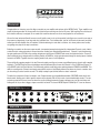
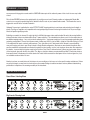
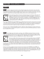
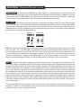
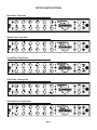
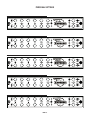
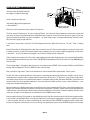
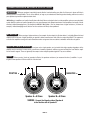
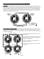
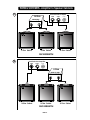
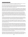
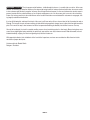
Owner’s Manual
Hello from the Tone Farm
...You, smart player and intuitive human, have put your trust in us to be your amplifier
company. This is something we do not take lightly. By choosing this instrument to be a
part of your musical voice, you have become part of the Mesa family...WELCOME!
Our goal is to never let you down. Your reward is that you are the new owner of an amp,
bred of fine all tube heritage...benefiting from the many pioneering and patented Mesa
circuits that led to the refinement of your new model. We feel confident, this amp will
inspire many hours of musical satisfaction and lasting enjoyment. It was built with you in
mind, by players who know the value of a fine musical instrument and the commitment it
takes to make great music. The same commitment to quality, value and support we make
to you...our new friend.
IMPORTANT SAFETY INSTRUCTIONS
Read these instructions.
Keep these instructions.
Heed all warnings.
Follow all instructions.
Do not use this apparatus near water.
Clean only with dry cloth.
Do not block any ventilation openings. Install in accordance with the manufacturer’s instructions.
Do not install near any heat sources such as radiators, heat registers, stoves, or other apparatus (including amplifiers) that produce heat.
Do not defeat the safety purpose of the polarized or grounding-type plug. A polarized plug has two blades with one wider than the other. A grounding type plug
has two blades and a third grounding prong. The wide blade or the third prong are provided for your safety. If the provided plug does not fit into your outlet,
consult an electrician for replacement of the obsolete outlet.
Protect the power cord from being walked on or pinched particularly at plugs, convenience receptacles, and the point where they exit from the apparatus.
Only use attachments/accessories specified by the manufacturer.
Unplug this apparatus during lightning storms or when unused for long periods of time.
Refer all servicing to qualified service personnel. Servicing is required when the apparatus has been damaged in any way, such as power-supply cord or plug
is damaged, liquid has been spilled or objects have fallen into the apparatus, the apparatus has been exposed to rain or moisture, does not operate normally,
or has been dropped.
To insure proper ventilation always make sure there is at minimum four inches (101.6mm) of space behind the rear of the apparatus. The ventilation should not
be impeded by covering the ventilation openings with items, such as newspapers, tablecloths, curtains, etc. Do not impede ventilation by placing objects on top
of the apparatus which extend past the rear edge of its cabinet.
No naked flame sources, such as lighted candles, should be placed on the apparatus.
The apparatus shall not be exposed to dripping or splashing and no objects filled with liquids, such as vases, shall be placed on the apparatus.
WARNING: To reduce the risk of fire or electric shock, do not expose this apparatus to rain or moisture.
The AC plug is the mains disconnect. The plug should remain accessible after installation.
WARNING: EU: permission from the Supply Authority is needed before connection.
WARNING: Always make sure proper load is connected before operating the amplifier. Failure to do so could pose a shock hazard and may result in damage
to the amplifier.
Do not expose amplifier to direct sunlight or extremely high temperatures.
Always insure the amplifier is properly grounded. Always unplug AC power cord before changing fuse, tubes or removing chassis. Use only same type and
rating when replacing fuse.
Avoid direct contact with heated tubes. Keep amplifier away from children.
To avoid damaging your speakers and other playback equipment, turn off the power of all related equipment before making the connections.
Do not use excessive force when handling buttons, switches and controls. Do not use solvents such as benzene or paint thinner to clean the unit.
Always connect to an AC power supply that meets the power supply specifications listed on the rear of the unit. Export models: always insure unit is wired for
proper voltage. Make certain grounding conforms with local standards.
YOUR AMPLIFIER IS LOUD! EXPOSURE TO HIGH SOUND VOLUMES MAY CAUSE PERMANENT HEARING DAMAGE!
Your Mesa/Boogie Amplifier is a professional instrument. Please treat it with respect and operate it properly.
READ AND FOLLOW INSTRUCTIONS OF PROPER USAGE.
Table of Contents
Precautions________________________________________________________________________________ 0
Overview_________________________________________________________________________________ 1-2
FRONT PANEL CONTROLS & FEATURES
MODES: CLEAN, CRUNCH, BLUES, BURN_____________________________________________________ 3-4
GAIN______________________________________________________________________________________ 5
TREBLE_ __________________________________________________________________________________ 5
MID_______________________________________________________________________________________ 6
BASS______________________________________________________________________________________ 6
REVERB___________________________________________________________________________________ 6
MASTER___________________________________________________________________________________ 7
CH1 / FTSW / CH2 SWITCH____________________________________________________________________ 7
CONTOUR_______________________________________________________________________________ 7-8
STANDBY__________________________________________________________________________________ 8
POWER____________________________________________________________________________________ 8
REAR PANEL CONTROLS, SWITCHES & JACKS
EXTERNAL SWITCHING______________________________________________________________________ 9
EFFECTS LOOP_____________________________________________________________________________ 9
POWER SELECT_ __________________________________________________________________________ 10
FULL POWER______________________________________________________________________________ 10
5 WATT_ __________________________________________________________________________________ 10
SPEAKERS________________________________________________________________________________ 11
FACTORY SAMPLE SETTINGS________________________________________________________________ 12
PERSONAL SETTINGS______________________________________________________________________ 13
DIAGNOSING TUBE PROBLEMS___________________________________________________________ 14-15
BIAS ADJUSTMENT ARTICLE_____________________________________________________________ 16-18
SPEAKER IMPEDANCE MATCHING AND HOOKUP GUIDE______________________________________ 19-24
FEATURE ARTICLE: ON PENTODES, TRIODES & IRISHMEN by Randall Smith_____________________ 25-27
TUBE TASK CHARTS: 5:25 & 5:50__________________________________________________________ 28-29
PART SHEETS: 5:25 & 5:50________________________________________________________________ 30-31
Operating Instructions
Overview:
Congratulations on choosing one of the Express models as your amplifier and welcome to the MESA Family! These amplifiers represent the latest generation of a time-proven circuit that has been evolving over the last 22 years. With inspiring Tone and a layout
that’s intuitive and easy to navigate, it’s no wonder this model has become one of our most popular line of instruments.
We use the term instrument literally because you will quickly come to rely on the myriad of truly Expressive sounds in your amp as
it becomes an integral part of your tone and your individual voice. Feel confident that, just like a fine musical instrument, we handcrafted your all-tube amplifier here in Petaluma, California adhering to a code that is centuries old…where patience and scrutiny
are guiding every step on the way to excellence.
Both Express models use the same super versatile, tone-packed preamp featuring two fully independent Channels, each of which
contain two style enhanced modes to choose from when creating your footswitching preferences. Channel 1 hosts the blooming
low-gain sweetness of CLEAN or the snarling mid-gain percussiveness of CRUNCH and covers the rhythm territories. Channel 2
offers a different face to mid-gain with the howling honesty of BLUES or a high-gain adventure through the searing layers of molten
harmonics in BURN. Together these two inspiring modes invite years of solo exploration.
These stylistically opposing modes in the two Channels enable your Express to roam many different genres of music with complete
legitimacy. The R&B, Roots or Blues minded player would find themselves at home with Channel 1 set to CLEAN and Channel 2
set to BLUES, while the Rock, Metal or Punk influenced guitarist would likely prefer switching between CRUNCH and BURN. This
ability to reconfigure the Channels and morph personalities creates a Jekyll/Hyde platform from where any classic or modern tone
you are aiming at can be found in seconds. The ability to adapt is part of what defines a classic instrument.
To add to the soul-power of these four modes, each Channel boasts an assignable/footswitchable CONTOUR mode with its own
blend control, allowing you to dial in specific amounts of this dynamic EQ circuit for each of your footswitchable sounds. The sizeenhancing sound of this preset curve has been the result of polling thousands of happy customers over our 38 year history and
finding most all of you want a bigger, crisper sound with less mids. The classic MESA Graphic EQ Mid-Dip “V” curve has become
FRONT VIEW: Express 5:25
™
CLEAN
ON
O
F
F
CRUNCH
GAIN
TREBLE
MID
BASS
REVERB
MASTER
BLUES
CONTOUR
CLASS A
REAR VIEW: Express 5:25
ON
FT SW
™
PAGE 1
STANDBY
ON
O
F
F
BURN
POWER
5 WATT
FT
SW
CH 2
INPUT
ON
FT SW
CH 1
Overview: (Continued)
synonymous with huge guitar sounds and this CONTOUR feature puts all the authentic power of this circuit into one easy to dial
control.
Rich all-tube REVERB enhances the spatial quality of your Express and each Channel provides an independent Reverb Mix
control so you can get the perfect blend of this beautiful effect for each of your footswitchable sounds. The Reverb effect can be
triggered on and off via the included Footswitch.
Outboard Processing is handled by the series EFFECTS LOOP, keeping patching to a minimum and protecting tonal integrity a
priority. The Express amplifiers are compatible with most good quality processors and using this feature for all of your rack-type
effects will produce gratifying results.
Both Express models, the bouncy 25 watt 5:25 with its 2xEL84 9-pin power tubes and the bolder 50 watt 5:50 running 2x6L6 octal-base pentodes, feature our patented Duo-Class™ power switching. This valuable feature allows you to run the output tubes in
two different wattage ratings – very cool, but what’s amazing is this – each power mode has it’s own tone-spawning operating class
and wiring configuration! Choose the full power mode of either amp (25W in 5:25 or 50W in 5:50) for Class AB running in a PushPull configuration for punch, authority and headroom. Then, kick down to the 5 watt mode for the ultimate in sweet clipability…
now you’re running one tube in pure Class A wired in Single-Ended configuration. Obviously we were thankful the patent office
saw the possibilities and rewarded our efforts with a patent, but what excites us is the look on players faces when they experience
this feature…hear and feel this bi-polar magic for the first time. Duo-Class™ delivers the best of these two iconic power styles in
all their authentic glory with the flick of a switch! The Express 5:25 also features our patented Dyna-Watt™ Power that creates a
time-specific burst of headroom at the initial attack of the notes that far exceeds the rated power of the circuit and gives the 5:25
an incredible sound and feel all its own.
Now that you have an overall picture of the features in your new Express Let’s move on to the specific modes and features. Before
we go there though, you may want to check out these two sample settings to audition two basic and very different footswitching
personalities to experience the amazing versatility of this instrument.
INSTANT GRATIFICATION
Sweet Clean / Howling Blues
Big Crunch / Burning Lead
PAGE 2
FRONT PANEL: Controls & Features
THE MODES
CHANNEL 1
CLEAN: This is the lowest gain of the four modes in your Express and it is voiced to deliver beautiful sparkling and warm clean
chording sounds. The CLEAN mode has the greatest dynamic range of all the modes as the signal here is not compressed with
any additional gain as are sequentially, the other three. Because of this more traditional gain structure, many players that are looking for a vintage style response from the Express should be at home here. At higher GAIN settings this mode
delivers great old school lead sounds and if you are a player that is reliant on overdrive pedals for a certain
sound (although we greatly encourage you to explore the other three modes – especially BLUES - for overdriven applications), CLEAN will likely be the best match for retaining more dynamic range.
The taper of the GAIN control is calibrated such that at the lower settings 9:30 - 11:00 the sound will be very
bright and skinny, as you approach 12:00 – 2:00 warmth and richness appears and the signal stays clean.
From the 2:30 – 4:30 range a soft fur will begin giving way to a vintage style break-up and finally at its maximum setting (5:30) the
signal will be fairly pushed and overdriven. Keep in mind that these are approximate descriptions of the sound and that your own
personal playing style, guitar, pickups and most of all touch, will determine how this mode reacts at specific settings.
CRUNCH: This mode excels at higher gain rhythm sounds and though it is quite a bit gainier than the CLEAN mode, it’s voiced
to retain as much dynamic range as possible. It cleans up nicely at the lower end of the GAIN control (9:00 – 12:00) and therefore
can be used as an alternate type of clean sound, though it will always retain a bit more aggressive midrange and will not have as
much top end sparkle as CLEAN.
Between 12:00 – 2:30 is where the classic rock rhythm sounds live, especially with humbucking pickups and
mahogany guitars. This is a sound that is overdriven, crisp and urgent, but not overly saturated. From 2:30
on up to the maximum GAIN setting (5:30), the sound becomes more saturated and begins to get a bit thicker
and creamier. This region is great for solo sounds where more urgency is needed, as it has ample gain but is
still tight tracking and responsive.
Be sure to experiment with the CONTOUR feature in the CRUNCH mode as some amazing sounds appear as a result of this combination. We tend to like the CONTOUR set at 12:00 with the GAIN at around 4:00 for a great rock rhythm sound. Again, these are
approximate settings as everyone will have different styles, guitars, pickups and touch.
PAGE 3
FRONT PANEL: Controls & Features (Continued)
CHANNEL 2
BLUES: Channel 2 is aimed more at single note soloing, although both of the modes contained in this channel work well for
rhythm playing as well if the GAIN controls are set in their lower regions. BLUES is the lower gain of the two modes in this Channel and owns the zone between the CLEAN and CRUNCH modes. It delivers a classic, old-school voice that can be set to achieve
anything from a warmer clean sound, through a purring, soft-clip break-up on up to a mournful, howling lead sound.
Because it derives its architecture more from a medium gain lead circuit, it will always be a little warmer and
thicker than the CLEAN mode even at the lowest regions of the GAIN control. Therefore, if you wish to use
BLUES as an alternate clean sound or, you prefer to use Channel 1 set to CRUNCH for an urgent lead sound
and BLUES as your main clean, you will need to run the GAIN very low (9:30), the TREBLE higher (1:30
– 2:00) and the MID low ((8:00 – 9:30). Following this scheme will give you the closest approximation of the
scoop and sparkle present in the CLEAN mode.
When using the CONTOUR feature with the BLUES mode, you will likely find the best results in the lower range of the control (9:30
– 1:00). Above this region the mid-dip EQ curve of the CONTOUR can get a little too extreme for most players searching for bluesy
solo sounds. However, this same curve can be a benefit to creating sweeter, more sparkling clean sounds as its mid-dip scoops
some of the heavier mids that are needed for a fat single note sound, but can be a bit clunky for a great clean.
Also be sure to check out combining the BLUES mode with the 5 Watt Class A setting of Duo-Class™ to explore some really cool
low-volume blues magic. The single-ended wiring produces a sweetness that enhances the BLUES mode perfectly, not to mention
that your roommates will love you for it.
BURN: This is the highest gain of all the modes in your Express and it is BURN that characterizes Channel 2 as the Lead
Channel. As mentioned in the Overview, this circuit has been evolving over the last 22 years and after you’ve dipped your guitar
into this river of undulating harmonics, you’ll come away a new soloist…baptized by gain that’s inseparable from the notes. Tight
and focused, searing yet vocal, BURN delivers the ultimate in Expressive high-gain.
At the lower end (8:30 – 9:30) of the gain range you will find a small overlap with the top zone of the BLUES
mode, although a bit fatter and more saturated, that offers some cool Blues or Roots melody line possibilities. The similarities end abruptly here and a wide region of amazing Rock sounds appear in the middle (9:45
– 2:00) range of the GAIN control. This is where you will likely find the most musical and versatile of your
high-gain sounds…small adjustments here can make big changes in the attack and the body of the notes.
From there on up (2:15 – 5:30) the smoldering intensity of this channel is unleashed to produce a sound that is pure molten MESA.
Legato and fluid, yet with beam-like clarity and sustain, BURN is testimony that 38 years ago on a mountainside in Marin County …
we invented high gain.
Perhaps no other mode in your Express showcases the power and sonic potential of the CONTOUR feature like BURN. Here,
the entire range of the CONTOUR control produces useful and in fact, phenomenal gain sounds. The lower (8:30 – 11:00) range
combined with lower GAIN settings works great for widening mid-gain single note solo sounds, while higher settings (11:30 – 5:30)
combined with more GAIN unveil a wall of crushing aggression that is equal to, in menace, our own Dual Rectifier™ line. Be sure
to explore this hellacious realm of sounds when you’re ready for some really big guitar sounds.
PAGE 4
FRONT PANEL: Controls & Features (Continued)
GAIN: As with all tube amplifiers, especially those with higher GAIN circuits, the GAIN control is by far the most powerful control
in the amplifier. It determines the overall GAIN amount you will be working with (how clean or saturated the signal is) in any given
channel or mode by metering the signal in the beginning stages (first tubes) of the preamp. It is also a very important Tone control
as well.
CLEAN
Generally speaking, lower the settings of the GAIN control (below 12:00 in all modes) produce sounds that
are less saturated, cleaner, brighter and more dynamic. As the GAIN control is increased the sound begins
to get thicker and warmer and the dynamic peaks get softened by natural, sweet tube compression as the
TREBLE
MID
BASS
signal
moves toward
saturation.
This is REVERB
pretty much MASTER
an across the board (or Channels) response, asCONTOUR
these
global behavior traits remain constant regardless of the individual architecture of the modes themselves.
ON
O
F
F
CRUNCH
GAIN
BLUES
INPUT
FT SW
CH 1
5 WATT
FT
SW
CLASS A
CH 2
FT SW
BURN
Another simple guideline to follow that might make dialing for your sounds easier is this; as the GAIN goes
up…the BASS should come down. Following this scheme will help you avoid flub and retain a tight, focused attack.
So for example, if you are in Channel 1 CRUNCH and you want to max the GAIN (5:30) for a rhythm sound, you would want to run
the BASS control somewhere around 10:30 to keep the sound tracking tight. In the BLUES mode of Channel 2, things would be a
bit more flexible. If you wanted to run the GAIN just high enough to have a nice fury break-up when you lean into it (1:00 – 2:00),
you will be able to run the BASS a little higher (11:00 – 12:00) because there is less GAIN in the mode to begin with and you are
not using an extreme setting of the GAIN control.
NOTE: If you need very high GAIN settings to achieve the type of sound you are after, try looking to the CONTOUR for any added
low-end enhancement as this circuit comes later in the preamp and is less likely to bloat the sound. If the top-end enhancement is
unwanted, reduce the TREBLE.
Just remember that as the internal gain structure of the Modes gets increased across the Channels, so does the need to carefully
blend the GAIN and BASS, and in fact all the controls, to keep balance and cohesiveness in your Tone.
NOTE: Avoid extreme settings of both GAIN and TREBLE at the same time as the likelihood of annoying microphonic tube problems increases. If you need one set high to achieve the sound you are after, reduce the other to ensure uninterrupted performance.
TREBLE: As in most tube guitar amplifiers, the TREBLE control (in both channels of your Express) is the most powerful of the rotary
controls and is next in line only to the GAIN control as a shaping tool. Because it is first in the signal path of the tone controls - and
from here the Middle and Bass receive their signal - it is by far the dominant tone control. For this reason the setting of the TREBLE
control is very important for equal representation of the three frequency regions to appear at their respective controls. Like most of
the controls on your Express, there is an optimum region of the TREBLE control where ample top end is mixed in and yet enough
signal is still passed on to the MIDDLE and BASS controls.
AN
ON
O
F
F
ES
TREBLE
ON
As you might surmise, here is the sweet spot. There are definitely great sounds above and below this middle region
POWER
(11:00
between MASTER
the TREBLE control and the other two tone controls
is compromised.
MID - 1:30), but
BASSthe balance
REVERB
CONTOUR
FT SW
CH 1
GAIN
5 WATT
FT
SW
CLASS A
CH 2
ON
FT SW
PAGE 5
STANDBY
ON
O
F
F
RN
POWER
STANDBY
ON
O
F
F
NCH
ON
ON
FRONT PANEL: Controls & Features (Continued)
MID: The MID control is responsible for the blend of midrange frequencies in the mix and though its effect is not as dramatic as
that of the TREBLE control, it plays an integral part in achieving any sound in your Express. It is capable of changing the feel dramatically as it blends in a group of frequencies that tend to soften or stiffen the way a sound feels to play.
Most players tend to lean in the direction of lower MID control settings (7:00 - 11:00) where a scoop in this region produces girth (by letting the Bass become a little more dominant) and a lack of punch lendsON a more compressed, even
feel to the strings and therefore less apparent resistance to the pick. As the MID control is increased, (11:30 - 1:30) the
POWER
BASSis rounded-out
REVERB and filled-in
MASTER with a focused mid attack appearing ratherCONTOUR
sound
quickly. As you would guess, the feel starts
STANDBY
to change - becoming more resistant. Above this region the MID control could be used to compensate for either weaker
ON
pick-ups or for times when a specific deficiency is produced by either an extremely high setting of other tone controls,
or a physical anomaly in the room. While these MID control settings (2:00 - 5:00) can introduce added gain and create
enhanced focus, the trade-off will be a stiffer, more forward, less compressed feel.
ON
O
F
F
FT SW
CH 1
TREBLE
MID
5 WATT
FT
SW
CLASS A
CH 2
ON
O
F
F
FT SW
BASS: The BASS control in your new Express works similarly in both channels in that it determines the amount of low frequencies present in a sound. However, the style of lows it mixes in changes from channel to channel. Like the MID control, it falls in line
signal-wise after the TREBLE control and the same scheme applies. When the TREBLE control is set high, the effectiveness of the
BASS and MID controls is reduced. If the TREBLE control is set low these two controls become dominant.
ON
O
F
F
ON
For the most balanced sound and a balance of power between the three rotary tone controls, try to use the TREBLE
POWER
control
in its middle
ranges. This scenario produces nearly equal representation
of all the frequencies on the tone controls
REVERB
MASTER
CONTOUR
STANDBY
and provides a great neutral starting point for further tweaking.
FT SW
CH 1
MID
BASS
5 WATT
FT
SW
CLASS A
CH 2
ON
O
F
F
ON
FT SW
Note: The BASS control in both channels of your Express is very powerful and though we have taken steps to ensure
a balanced tone is easy to achieve, it is wise to blend with subtle nuance in mind. This is especially true in Channel 2
when using either the regular Channel 1 style gain circuitry cranked, or the DRIVE circuitry for higher gain lead sounds. A good rule
to follow is this; as you increase the GAIN reduce the BASS. Following this scheme will retain balance and keep the attack of the
notes tight, dynamic and touch sensitive.
REVERB: Your new Express amplifier is equipped with a rich, natural sounding all-tube Reverb circuit. The REVERB control enables
you to dial-in just the right amount of Reverb to be mixed with the dry signal. It is normal for extreme settings of the REVERB control
to slightly alter the character of the amplifier as the voicing of the Reverb circuit becomes more dominant in the mix.
NOTE: Avoid using high setting the REVERB control when High Gain and Treble settings are in use. This reduces the
ON
likelihood of annoying microphonic problems occurring.
ON
O
F
F
FT SW
CH 1
BASS
REVERB
MASTER
POWER
5 WATT
FT
SW
CONTOUR
CLASS A
CH 2
STANDBY
ON
O
F
F
ON
FT SW
PAGE 6
FRONT PANEL: Controls & Features (Continued)
MASTER: This control is the master feed from the end of the pre-amp to the driver stage and the Effects Loop. As you can see each
Channel is fitted with its own MASTER control, enabling both channels relative volumes to be matched regardless of their extremely
different sound styles and gain signatures. The MASTER control makes possible a wide range of sounds through its ability to use very
low Gain sounds at high volumes and conversely, high Gain sounds at low volumes and everywhere between.
ON
O
F
F
CH 1
REVERB
MASTER
Again, we suggest using the MASTER control in its sensible ranges (9:00 - 2:00). Here, the channels will be easier
POWER
to match with each other and the Effects
CONTOURLoop will see more reasonable signal levels.
ON
FT SW
5 WATT
FT
SW
CLASS A
CH 2
STANDBY
ON
ON
NOTE: Because the MASTER control creates the
send to the Effects Loop, extreme settings will cause a large
signal to be sent to the Loop for that Channel. Not only may this cause possible overloading of the processors Input
stage, but will make balancing both channel’s Effect Send level difficult.
O
F
F
FT SW
CH 1 / FTSW / CH 2:
This 3 position mini toggle allows manual selection the Channels when the Footswitch is not connected. When the switch is in the CH. 1 (switch up) position Channel 1 will be activated and the green LED will be illuminated. The
center position labeled FTSW activates the footswitch. The lower position, CH. 2 (switch down) activates Channel 2 and the red
LED will come on.
ON
O
F
F
MASTER
ON
NOTE: When the Channel Select switch is in the FTSW (center) position and the Footswitch is not connected,
POWER
the default setting is Channel
CONTOUR1 active.
FT SW
CH 1
5 WATT
FT
SW
CLASS A
CH 2
STANDBY
ON
O
F
F
ON
NOTE: The indicator LED above the CHANNEL
button on the Footswitch is a dual-color type that tracks the
colors on the Front Panel Channel LED indicators. It will appear green in Channel 1 and change to red when
Channel 2 is activated.
FT SW
Now let’s move to the individual controls and go over how they interact to achieve the sound you’re looking for.
CONTOUR: These two sets of 3 position mini toggles and rotary controls make up the amazing Channel specific, auto-assignable/footswitchable CONTOUR feature. This circuit puts all the power of our popular graphic EQ into one simple to dial control that
allows you to blend in the amount of EQ you wish to mix with your dry signal. The preset curve is based on the
classic “V” setting that 90 percent of all MESA graphic aficionados use, which scoops the mids while boosting the
ON high frequencies, to create a sound that is absolutely huge.
low and
ON
O
F
F
FT SW
POWER
5 WATT
CONTOUR
CLASS A
ON
O
F
F
FT SW
The mini toggles operate much the same as the Channel Select switch; ON (switch up) activates the CONTOUR
ON OFF (switch center) defeats the CONTOUR and FTSW (switch down) allows you to trigger the CONfeature,
TOUR from the Footswitch.
STANDBY
NOTE: The LED above the CONTOUR button on the Footswitch is a dual-color type that tracks the color of the Channel’s CONTOUR LED’s when the Channel button on the Footswitch is used to switch between the Channels. Channel 1 activates a green
CONTOUR LED while Channel 2’s CONTOUR is indicated by the red side of the LED.
The mid-dip of the CONTOUR, while it enhances clean and bluesy sounds very nicely in the lower (7:30 – 11:30) range of the
control, is especially effective in creating menacing high gain sounds in both Channels 1 and 2. Here, the CONTOUR can be applied more liberally without the risk of sounding too edgy (due to inherent tube compression) and some truly outrageous sounds
start to appear in both CRUNCH and BURN at around noon (12:00). As you pass 3:00 and the CONTOUR is increased toward
PAGE 7
FRONT PANEL: Controls & Features (Continued)
CONTOUR: (Cont.)
maximum, the EQ effect becomes extreme and a realm of sounds that are hard to believe appear.
Tight, percussive lows and rich layers of chirping upper harmonic expression make the sound and feel dangerously addictive to
play. The possibilities are almost limitless when you combine the sonic personalities of the four Modes with the versatility and
power of the CONTOUR feature. Be sure to spend some time in each of the Modes exploring this inspiring frontier of sounds.
STANDBY: Perfect for set breaks...this toggle switch also serves an even more important purpose. In the STANDBY position (switch
up), the tubes are at idle so that during power up they may warm up before being put to use.
Before the power is switched on, make sure the STANDBY switch is in the STANDBY position. Wait at least
30 seconds and then flip the STANDBY switch to its ON position. Following this simple warm up procedure helps in
preventing tube problems and increase their toneful life substantially.
POWER: This switch delivers the A.C. power to the Express. Make sure the unit is properly grounded ( all three terminals of the A.C.
power cord must be connected whenever possible and that the proper voltage is present. Follow the cold start procedure described
in the ON/STANDBY section above when powering up your new Express amplifier.
NOTE: Never alter the A.C. power cord in any way.
Now let’s spin your Express around and cover the Rear Panel Features.
PAGE 8
REAR PANEL: Controls & Features
EXTERNAL SWITCHING: These four ¼ “ jacks trigger the Channels, REVERB and CONTOUR feature of each Channel when
you want to control your Express with a master external switcher. In this way you can call up the sounds on your Express remotely
without connecting the Footswitch and have your effects and amp sounds respond to a single button (possibly
midi) program change command.
Simply connect standard unshielded (speaker) ¼” phone cables to these four jacks and short the “tip” to “ground” to
activate the features. This standard tip-to-ground “latching type” logic is supported on most all master switching devices so all you will have to do is program what ports on your switcher will be grounded under which programs.
EFFECTS LOOP:
The Express incorporates an internal EFFECTS LOOP to handle the interfacing of outboard processing. This
circuit is a patch point between the preamp and the power section and it is wired in series with the dry (un-affected) signal. Since
this loop is a series-type loop (as opposed to parallel - where the loop signal runs alongside the dry signal) it is
important that you use good quality processors “in the middle” of your amp. While the loop is compatible with most
processor Input/Output impedance demands, there can be a lot of room for sonic compromise in some of the less
expensive units. Remember that every part in your signal path is a tone part.
NOTE: Always use good quality shielded cable of the shortest possible length when patching your effects. One foot
lengths are preferable - with lengths of more than 3 feet (each cable) starting to roll off top end and reduce upper
midrange punch and top end clarity.
To use the EFFECTS LOOP;
1) Connect the SEND jack to your processor’s Input
2) Connect the RETURN jack to your processor’s Output
3) Adjust the processor’s Input/Output Level attenuator to achieve unity gain while plugging the RETURN cable in and out making
fine adjustments at the processor until you here no level difference.
NOTE: The EFFECTS LOOP is optimized for professional quality rack mount processors. Most pedal type effects work better in the
“front-end” between your instrument and the INPUT. You will experience some tonal changes because of the additional cable and
the fact that your instrument will no longer be going straight into the grid of the first tube. It’s up to you to decide if the trade off is
acceptable.
PAGE 9
REAR PANEL: Controls & Features (Continued)
POWER SELECT:
As mentioned in the OVERVIEW, your Express features our patented Duo-Class™ Power which allows you
to switch between two power ranges that run in both a different Class of Operation and a different Wiring Configuration. You will only
find this powerful feature on MESA amplifiers and it allows you to tune the power section for volume, Tone and feel… optimizing its
response for higher volume gig applications or lower volume recording and inspiring practice sessions
FULL POWER: The Full Power setting (50 watts in Express 5:50, 25 watts in the Express 5:25) runs in Class A/B and is wired in
a Push-Pull Configuration. This position (switch up) delivers the full rated power and would be the choice any time you need headroom
for clean sounds or bold, tight authority for all the sounds while playing with other people. Class A/B, when combined with a pair of
output tubes wired in a Push-Pull configuration, is the most efficient operating class and style of wiring and this scheme emphasizes
upper mid punch, low-end clarity and upper harmonic cut.
Express 5:25
Express 5:50
NOTE: 5:25 Owners! You’ve probably noticed by now that your Express seems far louder and more dynamic than any other 25 watt
amp you’ve heard. This is due to Dyna-Watt™, our patented way of wiring up a pair of EL84 output tubes that delivers a massive
burst of headroom at the initial attack of the note. From there a “timed sag” circuit loosens the feel as the notes decay and the result
is a little amp that is twice as powerful as its rated wattage on the attack – where you need it – but sweet and clippable, bouncy and
dynamic as the sound decays. The Express 5:25 with Dyna-Watt™ is one of our most enjoyable circuits to play as it is extremely
Expressive and friendly feeling on the strings as well as incredible sounding…5:50 owners, check one out sometime!
5 WATT: This position (switch down) reconfigures everything in your power section! The operating Class is switched to Class A,
which is far less efficient - but produces smooth, rich, silky harmonics and warm low end. Many vintage amplifiers were built with this
operating class. Now here is where we get tricky and is the basis of our patent. The wiring configuration is switched as well - from
Push-Pull to Single-Ended. This configuration - the first way tubes were ever wired – is again far less efficient but puts emphasis on
the even order harmonics. These are the second harmonic that lives one octave above the notes that are being played and they’re
the most pleasing of all harmonics. They sound sweet and add a fullness to the sound like no other, almost like a super subtle octaver
that is way back in the mix. Push-Pull circuits cancel out this second harmonic when the wave form is split in half and each half is
amplified separately and the sweet second harmonic is replaced by the punchier odd-order third harmonic…thus the substantially
louder impact of the Push-Pull configuration. Use the 5 WATT setting anytime you want the sweetest little amp response at home or
in the studio. It produces gorgeous clean sounds at very low volumes and when pushed, clips in the coolest way…even beyond our
favorite vintage classics.
The tone and versatility of this two mode power section leaves most other circuits pretty lacking. It’s truly like having two amps in
one package. And when you start combining the power choices with the myriad of sounds in the two Channels, the possibilities for
inspirational sounds are endless. Experiment and Enjoy!
PAGE 10
REAR PANEL: Controls & Features (Continued)
SPEAKERS: These jacks handle the output to speaker cabinets or the internal combo speaker in your Express. There is one
8 Ohm and two 4 Ohm jacks here and between these outputs, most popular speaker combinations can be accommodated. You’ll
find that different impedance loads change the way your amp sounds and feels - and though it is usually best to match the load you
are using to the matching SPEAKER impedance output – you may find a certain mismatch combination to your liking. For example,
some players like the tighter, bolder correct-match-response of an 8 Ohm speaker on the 8 Ohm
SPEAKER output. Others may prefer the scoopier, more elastic vibe of the 8 Ohm speaker on
the 4 Ohm jack. Feel free to experiment as your Express is capable of running with most any load
and producing amazing sound. If you prefer the sound of an impedance mismatch, by all means
go with the Tone.
NOTE: Using impedance mismatches in the low direction (i.e. a 2 Ohm load on the 4 Ohm output)
will cause the power tubes to wear a bit faster.
COMBO: Express combos use either one internal 8 Ohm speaker or, two 16 Ohm speakers (wired in parallel) to produce an 8 Ohm
load. If you wish to use an extension speaker cabinet (we make several matching Express cabinets, see you nearest dealer) you will
need to remove the combo’s speaker from the 8 Ohm SPEAKER output and connect it and the extension cabinet (also 8 Ohms) to
the two 4 Ohm jacks for a correct impedance match.
HEAD: Express heads can be used with most any speaker enclosure. Most MESA cabinets 1x12, 2x12 and 4x12 are wired to
8 Ohms. If you intend to use a non-MESA cabinet (we we’re sure you’ll find our cabinets superior both in sound and construction)
that is wired to 16 Ohms, connect it to the 8 Ohm SPEAKER output.
Now that we’ve covered the features and operation of your Express, it’s time to enjoy the best part…the sound and feel! We wish you
many years of inspiration, fulfillment and musical satisfaction from your new Express.
PAGE 11
FACTORY SAMPLE SETTINGS
Roots Clean / Texas Lead
Spankin’ Clean / Vocal Lead
Pushed Clean / Thick Crunch
Tight Crunch / Soaring Lead
Alternative Clean / Huge Crunch
PAGE 12
PERSONAL SETTINGS
PAGE 13
TUBE NOISE & MICROPHONICS: You may occasionally experience some form of tube noise or microphonics. Certainly no cause
for alarm, this quirky behavior comes with the territory and the Tone. Much like changing a light bulb, you don’t need a technician
to cure these types of minor user serviceable annoyances and in fact, you’ll be amazed at how easy it is to cure tube problems...by
simply swapping out a pre-amp or power tube!
First may we suggest that you set the amplifier up on something so that you can get to the tubes comfortably without having to bend
down. It also helps to have adequate lighting as you will need to see the tube sockets clearly to swap tubes. Use caution and common sense when touching the tubes after the amplifier has been on as they may be extremely hot! If they are hot and you
don’t want to wait for them to cool off, try grasping them with a rag and also note that the glass down around the bulbous silvery tip is
considerably less hot which makes it easier to handle. Gently rock the tube back and forth as you pull it away from its socket.
DIAGNOSING POWER TUBE FAILURE:
There are two main types of tube faults: shorts and noise. Both large and small tubes
may fall prey to either of these problems but diagnosis and remedy is usually simple.
If a fuse blows, the problem is most likely a shorted power tube and shorts can either be mild or severe. In a mildly shorted tube the
electron flow has overcome the control grid and excess current flows to the plate. You will usually hear the amp become distorted
and begin to hum slightly. If this occurs, quickly look at the power tubes as you switch the amp to STANDBY and try to identify one
as glowing red hot. It is likely that two of a pair will be glowing since the “shorted” tube will pull down the bias for its adjacent mates,
but one tube may be glowing hotter — and that one is the culprit. The other two are often fine — unless they’ve been glowing bright
red for several minutes.
Because there is no physical short inside the tube (just electrons rioting out of control) merely switching to STANDBY for a few moments then back to ON will usually cure the problem...at least temporarily. Watch the tubes carefully now. Should the problem recur,
the intermittent tube will visibly start to over heat before the others and thus it can be identified. It should be replaced with one from
the same color batch, shown on its label. Call us and we will send one out to you.
The severe short is not nearly so benign. In the worst cases, a major arcing short occurs between the plate and the cathode with
visible lightning inside the glass and a major noise through the speaker. If this is seen to happen, IMMEDIATELY turn the amp to
STANDBY. By this time the fuse probably will have blown. Such a short is usually caused by a physical breakdown inside the tube
including contaminate coming loose or physical contact (or near contact) between the elements. Replace it and the fuse with the
proper slo-blo type and power up the amp using the power up procedure as we described earlier in this manual.
TUBE NOISE: Often caused by contamination within in a tube, the culprit can usually be identified, and by lightly tapping on the glass,
you will probably hear the noise change. Hearing some noise through the speakers while tapping on the 12AX7’s is normal however.
And the one nearer the INPUT will always sound louder because its output is being further amplified by the second 12AX7.
The power tubes should be all but quiet when they are tapped. If crackling or hissing changes with the tapping, you have probably
found the problem. To confirm a noisy power tube, merely put the amplifier on Standby, remove it from its socket and turn it back on.
It will cause no damage to run the amplifier briefly with one power tube missing. You may notice a slight background hum, however,
as the push-pull becomes unbalanced. Whenever you are trying to diagnose a suspect tube, keep your other hand on the POWER
and STANDBY switches ready to shut them off instantly in the unlikely case you provoke a major short.
If you think you’ve located a problem tube but aren’t sure, we recommend substituting the suspect with a new one just to be sure of
your diagnoses. You will be doing yourself and us a big favor by just following the simple guidelines previously mentioned regarding
tube replacement. You’ll probably be successful with much less effort than is required to disconnect everything and haul the unit to a
technician who will basically perform the same simple tests. If the tubes are still within their six-month warranty period, we will happily
send you a replacement. Just note the color designation on the tube label so that we can send you the appropriate match.
PAGE 14
DIAGNOSING PRE-AMP TUBE PROBLEMS: Because your amplifier is an all tube design, it is quite possible that you will at some
point experience minor pre-amp tube noise. Rest assured - this is no cause for alarm and you can take care of the problem yourself
in a matter of minutes by simply swapping tubes.
Let us begin by saying; It is a “very good” idea to keep at least a couple of spare pre-amp tubes on hand at all times to insure uninterrupted performance. These minor pre-amp tube problems can take many forms but can generally be described in two categories:
Noise and Microphonics. Noise can be in the form of crackling, sputtering, white noise/hiss and/or hum. Microphonic problems usually
appear in the form of a ringing or high pitched squealing that gets worse as the gain or volume is increased thus are more noticeable
in the higher gain “HI” modes. Microphonic problems are easily identified because the problem is still present even with the instruments’ volume off or unplugged altogether - unlike pick-up feedback which ceases as the instrument is turned down. Microphonic
noise is caused by mechanical vibration and shock: think of banging a microphone around and you’ll understand where the word
came from.
The best way to approach a pre-amp tube problem is to see if it occurs only in one specific mode or channel. This should lead you to
the tube needing replacement. Then all that remains is to swap the suspect tube for a known good performer. If you cannot narrow
down the trouble to a specific mode or channel, the problem may be the small tube that drives the power tubes which is operational
in all modes and channels. Though rare, a problem with the driver tube would show up in all aspects of performance - so if you can’t
narrow the problem down to being mode or channel specific, you may want to try replacing the driver tube. Driver problems generally
show themselves in the form of crackling or hum in all modes of performance and/or weak overall output from the amplifier. Occasionally an anemic driver tube will cause the amplifier to sound flat and lifeless, but this is somewhat uncommon, as worn power tubes
are a more likely suspect for this type of problem.
Sometimes making the diagnosis is more trouble than it’s worth and it’s faster and easier to merely replace the small pre-amp tubes
ONE AT A TIME with a replacement known to be good. But MAKE SURE you keep returning the tubes to their original socket until you
hit the one that cures the problem. You’ll notice that tubes located nearer to the INPUT jack always sound noisier...but this is because
they are at the start of the chain and their noise gets amplified over and over by the tubes that follow. The tube that goes into this
“input socket” (usually labeled V1) needs to be the least noisy of the bunch. The tube that goes at the end of the preamp chain - just
ahead of the power tubes - can be quite noisy without causing any problem at all. The tubes in your amp have already been located
in the most appropriate sockets and this is why you should NEVER pull them all out at once and ALWAYS swap them one at a time.
ALWAYS return a perfectly good tube to its original socket. Also it’s a good idea to put the amp on STANDBY when swapping tubes
to reduce the heat build up in the tubes themselves and to prevent explosive noises (which can still occur even if you are pulling the
tubes away from their sockets gently) from coming through the speaker.
Remember, take your time, be patient and chances are real good that you can fix your amp yourself by finding and replacing the bad
tube. It kills us to see someone who has shipped their amp back to us...and all it needed was a simple tube replacement! If you must
send back your amp, remove the chassis from the cabinet by unscrewing the four mounting bolts on the bottom top. The chassis then
slides back like a drawer and comes out from the back. Remove the big power tubes and mark them according to their location from
left to right 1, 2 etc. They need to be wrapped separately with plenty of wadded up newspaper around them and put in a smaller box
within the larger carton. Remove the Rectifier tubes and wrap them also. You can leave the preamp tubes in or remove them and wrap
them separately being sure to label their location. (See Tube Task Chart.)
To wrap the chassis, use plenty of tightly wadded up newspaper so there is at least six inches of “crush space” between the chassis
and the cardboard box. Bubble wrap also works well, but please DON’T use styrene peanuts - they will shift during transit and get
lodged inside your electronics as well as allowing your amp to end up at the bottom of the box unprotected and possibly damaged.
Pre-amp tubes don’t normally wear out as a rule. Therefore, it is not a good idea to change them just for the sake of changing them.
If there isn’t a problem - don’t fix it. If there is no result from your substitutions, it may be possible that you have more than one
problematic tube. Though rare, this does happen and though it makes the troubleshooting process a little more intimidating, it is still
possible to cure the problem yourself.
NOTE: It is normal to hear a slight metallic ringing sound when tapping on the preamp tubes. As long as the tube does not break into
oscillation or start crackling or any other form of bizarre noise, it is considered normal and functional.
PAGE 15
BIAS ADJUSTMENT: (Part of a continuing series)
An Article written by Randall Smith that
we thought you might find interesting.
CATHODE ( )
GRID ( , )
SCREEN
GRID ( )
Here’s a question we often hear:
“Why doesn’t Mesa put bias adjustments
in their amplifiers?”
BEAMCONFINING
ELECTRODE ( )
..
.....
..
..
.
...
..
...
PLATE
( , )
Structure of a 6L6 / 5881
Beam Power Pentode.
Well, there’s a short answer and a long answer to this question.
The short answer is that during my 12 years of repairing Fenders, one of the most frequent problems I saw was bias controls that
were either set wrong or that had wandered out of adjustment due to vibration. As any honest tech will tell you, there’s lot’s of easy
money to be made by sprinkling “holy water” on amplifiers ... uh, what I meant to say is “Your amp needed biasing.” See what I mean?
What customer is going to argue with that?
It only takes a moment and a volt meter: The Fender diagram shows how: “Adjust this trim pot for - 52 volts.” That’s it. Nothing
more.
Now don’t be fooled into thinking that tubes “draw” more or less bias, they don’t. The way a bias supply is connected to a tube is akin
to a dead end road, it just trails off to nowhere without really completing a circuit. It’s a static voltage and regardless of what tube is
in the socket — or even if the tubes aren’t plugged in at all, it doesn’t change the bias voltage a bit.
So the end of the short answer is this: Since a bias supply needs to put out the right voltage and never vary, I wanted to build amplifiers
that were individually hard wired to the correct values and NEVER needed adjustment. And for 25 years, that’s how MESA/Boogies
have been built.
Time to change tubes? Just plug our tubes into any one of our amps and you’re DONE. No tech needed. NO bills and no BS about
biasing. And most important: The bias is RIGHT because it can’t change!
Now, you want the long answer? Here’s more information on how our hard-wired bias avoids trouble. Please read on.
But first, let’s make an important distinction. Our business is designing and building high performance amplifiers. And for this we
need tubes whose variance is within a narrow range. Our warehouse is full of rejects ...oh, they work — they just don’t perform within
our tolerance range. We have a very sophisticated computer - based tube testing system (nicknamed “Robotube”) that matches and
measures tubes over seven important parameters. It can even predict which tubes are likely to have a shortened lifetime — even
though they work perfectly during the test.
Because our business is building quality amps, we can afford to reject a lot of wayward tubes. The guys you hear complaining because
Boogies don’t have bias adjusters are primarily in the business of selling tubes - not amps. They don’t want to throw away 30 percent
of their inventory, so they promote the idea that tubes outside our parameters can be used to “customize” amplifiers and they criticize
us because our amps can’t be adjusted to accommodate their out-of-MESA tolerance tubes.
Now you might be thinking, “But I thought you just said that tubes don’t “draw” bias, therefore they don’t effect the bias supply and thus
it doesn’t need to be adjustable.” When you set the bias (whether it’s by selecting the right resistors, as we do, or adjusting a trimmer
— which is quicker) what you are doing is establishing the correct amount of idle CURRENT that flows through the power tubes.
But you can’t adjust the current directly, you can only change it by adjusting the amount of bias VOLTAGE that goes onto the tubes’
PAGE 16
BIAS ADJUSTMENT: (Continued) control grids. Voltage and current are NOT the same. Current is the AMOUNT of electricity, the
“quantity” — and is measured in amperes. Voltage is the degree of electric charge — like the “pressure” to use the old water analogy.
Let me illustrate how different voltage and current are:
When you scrape your feet across a carpeted floor in dry, wintery conditions, your body can become charged with 50,000 to 100,000
volts of static electricity. And when you reach for the door knob, a spark jumps and you feel it! The voltage is super high but the current (measured in micro-amps) is tiny - otherwise you would die from electrocution.
Contrast this with your car battery, which puts out a mere 12 volts. You can lay your hands right across the terminals and not feel a thing.
Yet the amount of current available can run to several hundred amperes .. enough to turn over a cold engine and get it started.
So current and voltage are two totally separate electrical parameters — though when you multiply them together, you get POWER,
which is measured in watts.
When you set the bias of an amplifier, you are adjusting the static VOLTAGE at the control grid of the tube in order to produce a
desired amount of idle CURRENT flowing to the tube’s plate. A small change in grid voltage, produces a large change in the amount
of current flowing — and that’s basically how a tube works. Say that again because it’s super important: A small change in voltage
at the grid causes a large change in current flowing to the plate. See, that’s the essence of amplification: A small change causing a
large change. And here it’s a small voltage change causing a large current change.
The bias conditions are what determines how much current flows through the big power tubes when you’re not playing. And what
drives your speakers is fluctuations in that current flow when you ARE playing. If the amount of current increases and decreases
440 times per second, then you’ll hear an A note. If the fluctuations in current flow are large and still at 440 per second, you’ll hear
an A that is LOUD!
But for purposes of biasing, it’s the amount of “plate current” flowing with no signal applied that’s important. Unfortunately current is
hard to measure because the circuit must be interrupted — as in “cut the wire” — and the meter spliced “in series” with the broken
circuit. But measuring VOLTAGE is easy. It is not necessary to interrupt the circuit because a voltage reading can be taken in PARALLEL with the circuit intact.
Thus, as a matter of convenience, most bias settings are given in volts at the grid ... even though current through the plate is the
important factor. In fact plate current is so inconvenient (and dangerous) to measure that Fender doesn’t even state what the correct
value should be. They only give the grid voltage that will produce that current. (That’s the minus 52.) But that only happens if the
tubes being used are “in spec.”
As long as the tubes ARE “in spec”, the right bias voltage will always give the correct plate “CURRENT” — but then there’s no need
for the bias voltage to be adjustable!
If the tubes are NOT in spec, then the only proper way to re-set the bias is to cut the circuit and measure the current while adjusting
the bias ... but no manufacturer I know even STATES the desired current value! Be that as it may, when the original bias voltage is
altered far enough, it will compensate for the tube’s abnormal performance and the correct amount of idle current flow may then be
restored. Clearly this is something most repair techs should not attempt.
Some newer amps have LED indicators connected to the circuit which will turn on when the right threshold of current flow has been
reached. This is an improvement, and almost worthy if you’re willing to accept resistors and lights added into your amplifier’s audio
path — which we aren’t.
The other “advantage” of this system is that it allows some amp manufacturers to avoid matching their power tubes. The thinking
is that adjusting the bias to each tube separately eradicates the inherent differences between the tubes by insuring that the same
current flows through each one.
PAGE 17
BIAS ADJUSTMENT: (Continued) Again, this has some merit .. but it’s still not as good as using tubes that are matched in the first
place because compensating for the mis-match causes the push-pull circuit itself to become unbalanced. Two wrongs don’t really
make a right.
Some of the other recommended biasing, “methods” — such as -”.. tubes running red hot, increase the bias .. sounds harsh and runs
too cool, turn it down ...” are guesswork at best. Luckily, one of the great things about tube amps is that they can usually stand some
abuse without causing any real harm ... at least not immediately. But don’t these alterations imply that you are second-guessing the
amp designer and that there’s a better set of operating conditions that the designer missed but the tube sellers have discovered?
Now some players may like the sound of their amp altered by tubes with extreme characteristics and with the bias set to help compensate. But often it is the mere novelty of change that they’re really responding to and when the amp goes back to the proper original
way, we’ve seen them be far happier still!
Because every part in every one of our designs has been meticulously evaluated, compared and stressed over — no matter how
seemingly insignificant it might be. And with every design we look for a “sweet spot” where all the parameters — including the bias
— come together to give the best sonic performance, consistently and reliably. Every part and voltage is important — yet no one
complains that these other parameters aren’t available for tinkering.
Consider our patented Simul-Class circuitry where there are two different bias voltages used for separate pairs of power tubes ...
and changing one voltage also changes the other. Great care goes into getting this just right and we think we’d be asking for trouble
to have it adjustable for the world to play with ... unless you like paying to have your amp messed up. Sorry, I meant to say, “Uh, ...
your amp needed biasing.”
If that doesn’t appeal to you, then merely plug a matched set of MESA tubes into one of our amps and you’re ready for tone. Guaranteed. You’d be amazed at the number of service calls we field every day that lead to a diagnosis of out-of-tolerance, non-spec tube
problems. To think these would be prevented by including a bias adjustment is something of an insult to you and us. If you put the
wrong size tires on your car, do you think changing the pressure will make them right?
Please, don’t think this is a blanket indictment of the other guys selling tubes — it isn’t. And their tubes aren’t all bad either. It just
doesn’t make sense to pay more of your hard earned cash for tubes that were probably made in the same Russian or Chinese factory and which have the possibility of being outside the performance window we select for your amp. And it pains us to hear the hype
and mystique built up around biasing when twenty-five years of evidence affirms our decision to make bias circuits that “never need
adjustment”. How much money and trouble that has saved MESA/Boogie players you couldn’t estimate.
Our rigorously tested and hand selected tubes are available at your nearest MESA/Boogie Pro Center or from us directly. Nobody
offers better price, quality or warranty than we do ... so why swerve?
Next time we’ll talk about our part in developing the great Sylvania STR 415 type 6L6 and how we’re on the verge of seeing something
fairly close reappear on the market. Remember, we still have some of these super rugged mondo-bottles available for older amps
— Boogies only please! Until then, Relax, Breathe and Nourish your soul!
Cheers!
MESA/Boogie Ltd.
PAGE 18
SPEAKER IMPEDANCE MATCHING & HOOK-UP GUIDE:
IMPEDANCE:
Wiring up speakers to provide the most effective load and making sure that all of them are in phase will help in
creating the best sound possible. This is not too difficult, as long as you understand a few things about loading and how to connect
your speakers to provide an optimal resistive load.
MESA/Boogie amplifiers can handle 4 and 8 ohms effectively. Never run below 4 ohms in a tube amplifier unless you are absolutely
certain that the system can handle it properly; this can cause damage to the Output transformer. A few amplifiers can handle 2 ohms
effectively without damaging them ( for example the MESA’S Bass 400+ ). You can always have a higher resistance ( 16 ohms, for
example ) without damaging results, but too low of a resistance will likely cause problems.
MIS-MATCHING: When running a higher resistance ( for example: 8 ohm output into 16 ohm cabinet ), a slightly different feel and
response will be eminent. A slight mismatch can provide a darker smoother tone with a little less output and attack. This response is
a result of the amplifier running a bit cooler. Sometimes when using more than one cabinet a mismatch will be the only option.
WHAT IS MY CABINETS IMPEDANCE: If you have only a single speaker, you just match that single speakers impedance to the
amplifier, and you are done. In many cases, you will have a number of speakers, and then you must calculate the “load” that the amplifier will need to support. There are generally three ways to wire multiple speakers together. They are as follows:
SERIES:
When you wire ( hook-up ) speakers in Series, the speakers resistance ( as measured in ohms ) is additive - i.e. putting two 8 ohm speakers in Series results in a 16 ohm load.
NEGATIVE =
POSITIVE =
BLA
BLA
DOW
Made by
Made by
DOW
SHA
CK
Electro-Voice
SHA
CK
Electro-Voice
Speaker B = 8 Ohms
Speaker A = 8 Ohms
SERIES: Connect the Negative side of Speaker A
to the Positive side of Speaker B
PAGE 19
SPEAKER IMPEDANCE MATCHING & HOOK-UP GUIDE: (Continued)
PARALLEL:
When wiring in parallel, the resistance of the speakers decreases. Two 8 ohm speakers wired in ( hooked-up )
Parallel results in a 4 ohm load. It’s easy to calculate the effect of a resistive load when all the speakers are all the same resistance.
It is really not suggested to wire different resistive load values in Parallel ( 8 and 4, 16 and 8 etc. ) The formula for figuring the total
impedance in Parallel is the multiplication of the two loads divided by the sum of the two loads - i.e. putting two 8 ohm speakers in
Parallel results in a 4 ohm load. Connect the Positive side of Speaker A to the Positive side of Speaker B - Connect the Negative
side of Speaker A to the Negative side of Speaker B.
Speaker B
8 Ohms
Speaker A
8 Ohms
BLA
BLA
DOW
Made by
Made by
DOW
SHA
CK
Electro-Voice
SHA
CK
Electro-Voice
NEGATIVE
POSITIVE
Total Load = 4 Ohms
COMBINATION OF SERIES & PARALLEL:
This is really just two sets of Series wired speakers connected in Parallel. This is
how you maintain a consistent load with multiple speakers. The importance of this is more evident when you have more than one
cabinet to connect to your amplifier. This is when you need to figure out the loads and how to wire them up without applying too low
of a resistance on the amplifier.
All 4 Spkrs. are 8 Ohms
SPEAKER A
Simply connect the Positive side of Speaker A to the Positive
side of Speaker C.
SPEAKER B
BLA
BLA
DOW
Made by
Made by
DOW
SHA
CK
Electro-Voice
SHA
CK
Electro-Voice
Connect the Negative side of Speaker A to the Positive side of
Speaker B. Next, connect the Negative side of Speaker C to
the Positive side of Speaker D.
And lastly, connect the Negative side of Speaker B to the
Negative side of Speaker D.
4 Eight ( 8 ) Ohm speakers wired in Series Parallel = a Total
Load of 8 Ohms.
SPEAKER D
BLA
POSITIVE
K SHA
CElectro-Voice
Made by
DOW
Made by
DOW
SHA
CK
Electro-Voice
BLA
SPEAKER C
NEGATIVE
PAGE 20
WIRING SCHEMES...Amplifier to Speaker Cabinets
1
Partial back view of amplifier
8 OHM
4 OHM
2
Partial back view of amplifier
4 OHM
8 OHM
4 OHM
4 OHM
8 Ohm Cabinet
3
Partial back view of
some Mesa amp
84Ohm
Ohm Cabinet
Cabinet
8 OHM
4 OHM
4 OHM
4 Ohm Cabinet
4
5
Partial back view of amplifier
4 OHM
8 OHM
16 OHM
Partial back view of amplifier
8 Ohm Cabinet
4 OHM
8 OHM
16 OHM
SAFE MISMATCH
16 Ohm Cabinet
16 Ohm Cabinet
SAFE MISMATCH
PAGE 21
6
WIRING SCHEMES...Amplifier to Speaker Cabinets
Partial back view of amplifier
Partial back view of amplifier
8 OHM
4 OHM
4 OHM
4 OHM
4 OHM
8 OHM
16 Ohm Cabinet
8 Ohm Cabinet
8 Ohm Cabinet
8 Ohm Cabinet
7
SAFE MISMATCH
CORRECT MATCH
8
9
Partial back view of amplifier
8 OHM
4 OHM
Partial back view of amplifier
4 OHM
8 OHM
8 Ohm
4 Ohm Cabinet
4 OHM
8 Ohm
SERIES BOX
4 Ohm
4 OHM
PARALLEL BOX
4 Ohm
CORRECT
MATCH
16 Ohm
4 Ohm Cabinet
16 Ohm Cabinet
PAGE 22
16 Ohm
CORRECT
MATCH
16 Ohm Cabinet
WIRING SCHEMES...Amplifier to Speaker Cabinets
10
Partial back view of amplifier
4 OHM
4 OHM
16 Ohm
8 OHM
SERIES BOX
8 Ohm
8 Ohm
8 Ohm Cabinet
8 Ohm Cabinet
8 Ohm Cabinet
SAFE MISMATCH
11
12
Partial back view of amplifier
4 OHM
4 OHM
CORRECT MATCH
8 OHM
Partial back view of amp
8 OHM
4 OHM
4 OHM
8 Ohm
PARALLEL BOX
16 Ohm
16 Ohm
8 Ohm Cabinet
16 Ohm Cabinet
16 Ohm Cabinet
SAFE MISMATCH
16 Ohm Cabinet
PAGE 23
16 Ohm Cabinet
WIRING SCHEMES...Amplifier to Speaker Cabinets
13
Partial back view of amplifier
16 Ohm
4 OHM
4 OHM
8 OHM
SERIES BOX
8 Ohm
8 Ohm
8 Ohm Cabinet
8 Ohm Cabinet
16 Ohm Cabinet
SAFE MISMATCH
14
Partial back view of amplifier
8 OHM
4 OHM
4 OHM
8 Ohm
PARALLEL BOX
16 Ohm
16 Ohm Cabinet
16 Ohm Cabinet
SAFE MISMATCH
PAGE 24
16 Ohm
16 Ohm Cabinet
ON TRIODES, PENTODES & IRISHMEN:
With apologies to Friends and Relatives from the Emerald Isle - who will make their appearance soon enough - the humor which
follows is dedicated to the memories of Spec McAuliff and Fae (Rafael) McNally, two of the True Greats.
As their numerical references suggest, the terms Diode, Triode and Pentode indicate the number of elements within the vacuum
tube i.e. two, three or five. All tubes also require a filament or heater which is not included in the count. Its purpose is to excite electrons from the cathode coating by raising the temperature such that they are able to boil out of the electron-rich coating material
and form a cloud of free electrons in the vacuum space surrounding the cathode.
Although the term filament and heater are often used interchangeably, there are specific differences: A filament is a directly heated
cathode where cathode coating is applied directly to the heating element. Examples are 5U4 twin diode rectifier and 300B triode
amplifier tubes. A heater, on the other hand, is a heating element which is separate from the cathode and is usually inserted within
the tubular cathode sleeve. Examples are 12AX7 twin triode amplifier and 6V6 or EL84 beam power pentode tubes. In all cases this
fundamental aspect of each tube’s construction is clearly visible, especially when the heating element is glowing red hot.
The cathode, then, would be considered the first numbered element because it is the source of the electrons. The word itself is
from the Greek literally meaning completely down, which implies a sense of central origin - like the center of the earth where
Tone begins. It might be said that an ecstatic audiophile experiences a positive catharsis, his soul being purified when his system
transports him to Audio Nirvana. The only trouble with taking this positive imagery too far is that the cathode is, unfortunately,
negative... at least electrically speaking. However this is easily remembered since virtually all musicians and audiophiles have also
experienced the more common negative catharsis when they emerge from the emotional rebirth kicking and screaming in rage and
frustration.
Once heated, the intrinsically negative electrons are energetic little fellows of almost no mass. Thus they may be accelerated almost instantaneously and will travel through a vacuum a nearly the speed of light. Being of like, negative charge, they tend to repel
one another and thus within the electron cloud surrounding the cathode, there is much jostling and elbowing as each one tries to
maintain his distance from all the others... unless there is a strong and universal attraction from an outside influence.
Visualize, if you will, a group of sub-atomic Irishmen milling about and in a repellent, negative state of mind. All are scowling and
none wants to have anything to do with the other. Now introduce a strong attraction say, a public bar, and you can easily picture an
orderly, if rapid movement of the lot in a single direction. This is what happens when a positively charged element called the anode
or plate is introduced into the vacuum.
The plate is the large metal element most prominently visible through the glass of an electron tube. It is the outermost element of
a tube’s structure and it surrounds all the others. The cathode is at the center radiating electrons outwards. As higher and higher
positive voltage is applied to the plate, the attraction for the electrons surrounding the cathode is increased and with nothing standing in the way, full uninhibited flow to the plate occurs... sort of like removing the doors and offering free drinks to the crowd of surly
Irishmen milling around outside. As electrons flow to the plate, the space charge will continually be replenished by further ‘boiling’
of the hot, electron-rich cathode as you can easily imagine other Irishmen impatiently taking up the places of those who’ve gone
inside - until the entire village is deserted.
Now, where do they come from and how do they emerge? Well, a grand and elegant lady once showed me how to revive flat champagne: She dropped a raisin into the glass. There was a dramatic and immediate increase in effervescence with the introduction of
a cathoding surface. Thousands of tiny bubbles suddenly appeared - and continued to flow from the raisin. Of course the bubbles
were made up of gas dissolved in the beverage, but the analogy makes it easy to visualize the loosely bound electrons dissolved
in the rich cathode coating as they effervesce from its heated surface.
But back to the electron flow. If the electrons are strongly attracted to a positively charged plate, then it follows that they are
strongly repelled by a negatively charged plate and they are. Thus, if an alternating current - such as comes from a transformer - is
applied to the plate, electrons will flow only during the times when the plate is positively charged. During periods of negative plate
charge, electron flow is stopped and the space charge of electrons remains compressed in the area around the cathode.
PAGE 25
ON TRIODES, PENTODES & IRISHMEN: (Continued) Thus a diode tube - one with a cathode and an anode - is mostly used to
rectify alternating current into direct current by passing it without restriction, but in one direction only. This also explains why closing
time is strictly enforced at Irish pubs: During normal operation, the traffic flow is similarly unimpeded and uni-directional toward the
bar and this process rectifies the work-day negativity. It goes without saying that no one leaves as long as the atmosphere around
the bar remains positively charged.
TRIODES: This section is a continuing technical treatise on the workings of Irish Pubs but to make it easier for the layman to
understand, it is explained in terms of vacuum tube technology. Enter the original bar - free beer and no doors. Well, it turns out that
some control over the flow can be a necessary and useful advantage. This led to the invention of those swinging louvered saloon
doors which are open at the top and bottom. They are patterned after the control grid of the vacuum tube, which is a loosely wound
coil of thin wire located between the cathode and the plate.
In a Triode the plate is always positively charged with high voltage D.C. and even though the grid is blocking the path, those negative electrons can still FEEL the strong attraction - just as the Irishmen can see in through the louvers of the bar doors. They know
what pleasures lie beyond, but to get there requires overcoming the negative influences controlling the access. This negative influence is typically called a Bias. In electronic terms that means the grid is supplied with a voltage which is slightly MORE NEGATIVE
than the already negative electrons. The more negative the Bias, the more it tends to neutralize the attraction of the plate and repel
the electrons back toward the cathode.
The Irish can be similarly charged with Bias, but unless you are Irish yourself, this type of Biasing may be more difficult to understand. The effect is similar though: The more negative the Bias, the more it impedes forward progress. Generally speaking though,
the electronic Bias of the grid is easiest to overcome, and for two main reasons: First, the Bias is set - like the bar doors - to allow
some passage. Second, the grid is mostly NOT THERE, like the louvered doors which are mostly open spaces. Unlike the plate
which is solid, the grid is like a coiled bed spring. It can create a repelling field but mostly it’s empty space in between widely separated windings of wire. It’s very easy to control the electrons as they pass through the grid’s force field: Changing the grid voltage
only slightly will have an enormous effect on how much current flows through... and that’s what AMPLIFICATION is: a small change
in voltage at the grid causing a large change in current flowing to the plate.
The purpose of the louvered bar doors is similar to that of the grid, namely, to give momentary pause while still revealing the
promise within. Hesitation mostly gives way to temptation, but there are those few stalwart Irishmen who think twice and decide
to come back later. Most just pause slightly then go on through. That is the purpose of the bar doors: to prevent everyone from
crowding in all at once - and as the door is made less of a barrier, wider spaces between the louvers, more of the bar’s attractive
influence is felt outside thus amplifying the  customer flow and increasing the crowd at the bar.
PENTODES:
Occasionally though, bar doors - even the louvered type - were found to be too effective, and too many customers
turned away. Something further was needed to increase the attraction of the bar and overcome the resistance created by the door.
Thus the cocktail waitress was invented.
Once again the idea was inspired by the vacuum tube. It had been discovered in some tubes, often large power types, that the
distance to the plate was too great to attract enough electrons past the negative influence of the control grid. So another grid coil of
fine wire was inserted between the first grid and the plate. This was called the screen grid and carrying a highly positive charge, it
functioned as a “bait” for the plate.
In a properly designed power tube such as an EL84 or a 6V6, the windings of the screen grid are precisely aligned to fall in the
shadow of the control grid. This way the electrons responding to the pull of the screen grid are lined up in sheets as they pass between windings of the inner control grid... only to find that they have been fooled! Once past the control grid and drawn toward the
screen grid, they discover...there’s almost nothing there. The path they’re on has them aligned to zing straight through the spaces
BETWEEN screen grid windings. So rather than a close and personal encounter, they just fly on past - and once they’re out that
far, there’s no stopping them. The influence of the plate takes over and - being solid metal and of the highest positive attraction - it
is at this final destination that the electrons congregate.
PAGE 26
PENTODES: (Continued) Thus the proper cocktail waitress - visible through the louvers - is scantily clad so as to be all the more
effective at reinforcing the attractive influence of her bar and by being located in between the door and the bar, she serves as bait
to lure customers past the door’s negative influence. Once through the door however, it is the rare Irishman who actually comes in
personal contact with the cocktail waitress as, for all intents and purposes, she - like the screen grid - turns out to be a vanishing
illusion. Yet, having come this far, the solid influence of the bar itself now takes over and attracts the customers to congregate, having happily reached their destination.
If you’re still following this and haven’t lost track of the count, you’ll know we’re still one element short of the five needed to make a
Pentode. This last part is a pair of beam-confining shields which being negatively charged, serve to direct the flow right toward the
plate. This is much the way a short entrance hall to the bar prevents wandering accidentally into the Men’s room on the way.
Once at the bar though, the circuit is complete and the process of soul-nourishing works its ritual magic. Biases having been overcome, illusory nightingales having vanished, the spirits truly soar and the once surly Irishmen now are filled with warmth, wit and
kindred friendship, enjoying the music and glowing nicely with their heaters on.
With appreciative thanks to the inhabitants of the Land of the Leprechaun, we have now concluded our little diversion into the
mechanics of proper bar lay-out.
A feature article by Randall Smith
Designer / President
PAGE 27
PAGE 28
PAGE 29
LED
pt# 395438
590150
590151
590738
590740
590740
LED LED
pt# 394251 pt# 394232
590736
590148
LENS
pt# 703330
590148
590151
ALL KNOBS
PT# 408015
590739
590739
2 SWITCHES LED pt#
pt# 607233 394201
590737
SWITCH
pt# 607233
3 JACKS
pt# 619356
2 SWITCHES
pt# 600631
590738
LED
pt# 395735
LENS
pt# 703330
SWITCH
pt# 619357
590739
FRONT PANEL: Express 5:25
SWITCH
pt# 607231
JACK
pt# 610120
SWITCH
pt# 607231
3 x DUAL JACKS
pt# 619357
REAR PANEL: Express 5:25
DOM pt#
790100
EXP pt#
795080
HOLDER pt#
790347
LENS pt#
703782
BULB pt#
703047
HOLDER pt#
703047
PAGE 30
LED
pt# 395438
LED
pt# 395438
590151
590738
590740
LENS
pt# 703330
590150
LED
pt# 394251
590736
590740
LENS
pt# 703330
590148
590148
ALL KNOBS
PT# 408015
590739
590151
LENS pt#
703330
LED pt#
395735
590739
2 SWITCHES
pt# 607233
590737
SWITCH
pt# 607233
590738
LED
pt# 395735
LENS
pt# 703330
SWITCH
pt# 619357
3 JACKS
pt# 619356
LENS pt#
703782
BULB pt#
703047
HOLDER pt#
703047
590739
FRONT PANEL: Express 5:50
SWITCH
pt# 607231
JACK
pt# 610120
SWITCH
pt# 607231
3 x DUAL JACKS
pt# 619357
REAR PANEL: Express 5:50
DOM pt#
790300
EXP pt#
795200
HOLDER pt#
790347
2 SWITCHES
pt# 600631
PAGE 31
NOTES
®
®
®
09/14/09