1
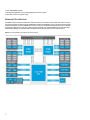
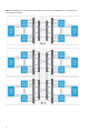
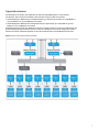
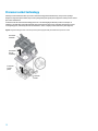
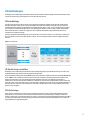
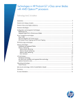
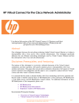
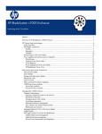
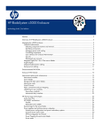
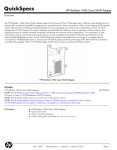
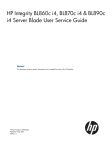
Technical white paper
Benefit from HP Integrity server blade
technology and architecture
HP Integrity BL860c i4, BL870c i4, and BL890c i4 Server Blades
Table of contents
Introduction
3
Integrity server blade architecture
HP Integrity BL860c i4 Server Blade details
Balanced I/O architecture
HP Integrity BL870c i4 Server Blade details
HP Integrity BL890c i4 Server Blade details
Scalable blade technology
Supported technologies
Supported enclosures
3
3
4
5
5
5
5
7
Processor technologies
Multilevel caches
Hyper-threading
Instruction replay technology
Integrated memory controllers and Scalable Memory Interconnect
Enhanced instructions-level parallelism
QuickPath Interconnect architecture
Thermal logic technologies
8
8
8
9
9
9
10
10
Reliability, availability, and serviceability technologies
Processor reliability, availability, and serviceability (RAS) improvements
Memory RAS features
Intel QPI RAS features
11
11
11
11
Processor socket technology
12
I/O technologies
PCIe technology
HP Smart Array controllers
SAS technology
Optional mezzanine cards
Networking technology
13
13
13
13
14
14
Configuration and management technologies
HP BladeSystem Onboard Administrator
HP Integrity iLO 3
HP Insight Control for HP-UX
15
15
16
16
Power management technologies
Power meter
OS power regulation
HP Dynamic Power Capping
16
16
16
16
Data security technology with TPM
17
Partition Technologies
Physical nPartition support
HP-UX virtual partitions
17
17
17
Conclusion
18
For more information
18
Introduction
This paper describes the architecture and implementation of major technologies in the HP Integrity c-Class server blades
based on the Intel® Itanium® processor 9500 series modules. The Integrity server blades architecture opens a chapter in
server scalability by using a common base two-socket (2S) base blade to build four- and eight-socket systems.
HP Integrity Blade Links attach to common base server blades to scale from two (BL860c i4), to four- (BL870c i4) or
eight-socket systems (BL890c i4). See figure 1 for a physical view of the three form factors.
It is assumed that the reader is familiar with HP Integrity server technology and has some knowledge of BladeSystem
architecture. For more information about the infrastructure components and complete specifications of each server
blade, visit hp.com/go/bladesystem.
Figure 1. HP Integrity BL860c i4, BL870c i4, and BL890c i4 Server Blade form-factor view
BL860c i4
BL870c i4
BL890c i4
Integrity server blade architecture
HP Integrity BL860c i4 Server Blade details
Figure 2 shows a block diagram for the base blade of the HP Integrity BL860c i4 Server Blade. The server blade features:
• Two Intel Itanium processor 9500 series module
• 24 DDR3 DIMMs operating at 1066 MTs. Supported DIMM capacities 4 GB, 8 GB, 16 GB, and 32 GB
• Three Gen 2 PCIe x8 Mezzanine I/O cards support
• Next-generation network adapters based on Emulex BE3 chipset that converge Ethernet and, Fibre Channel on one
adapter, at the price of 10GbE
• PMC8011 serial-attached SCSI (SAS) Controller supporting dual SAS hot-plug disk drives that could be configured as
RAID 1 or 0 or HBA mode. 512 MB battery-less embedded cache supported
• Optional trusted platform module (TPM) 1.2 support
• Dual USB 2.0 ports
• RN50 Radeon VGA
3
• Intel® 7500 IOH/ICH10 chipset
• HP Integrated Lights-Out 3 (iLO 3) manageability chip network accessible
• Blade Link connector for system scaling
Balanced I/O architecture
The BL860c i4 features PCIe Gen 2 with x8 link width mezzanine cards. In addition, x4 Gen 2 PCIe links connect to each of
the two Fibre Channel over Ethernet (FCoE) 10GbE LAN on motherboard (LOM) NICs. This is an uncompromised aggregate
32 GB/s I/O bandwidth. The Intel 7500 IOH PCIe controller connects to two Intel Itanium 9500 series processors, through
dedicated 25.6 GB/s links for a total of 51.2 GB/s aggregate bandwidth. This makes the BL860c i4 a system with a high
I/O bandwidth capability. The I/O bandwidth scales proportionately with the number of Intel 7500 per system.
Figure 2. HP Integrity BL860c i4 Server Blade system block diagram
4
HP Integrity BL870c i4 Server Blade details
By using the Integrity Blade Link-2, two base blades are combined to scale double the available system resources of a
single BL860c i4. Resources hosted on the ICH MEZZ Card (see figure 2) are not replicated. Refer to table 1 for a view of
the available resources for a BL870c i4. Now physical nPartition is supported.
HP Integrity BL890c i4 Server Blade details
By using an Integrity Blade Link, four base blades are combined to scale to quadruple the available system resources of
a single BL860c i4. Resources hosted on the ICH MEZZ Card (see figure 2) are not optional and not duplicated. Refer to
table 1 for a view of the available resources for a BL890c i4. Now physical nPartition is supported.
Table 1. HP Integrity server blades maximum supported configurations
System name
CPU sockets
CPU cores
DIMM slots
Hot plug disks
Mezzanine cards
10 Gb LOMs
BL860ci4
2
16
24
2
3
4
BL870ci4
4
32
48
4
6
8
BL890ci4
8
64
96
8
12
16
Scalable blade technology
HP Integrity server blades offer unprecedented flexibility to scale up your system. Each base server blade features a
Blade Link connector that allows two or four base blades to be connected together to form up to an eight-socket server.
The base blades are connected with Integrity Blade Links. You can choose between two Integrity Blade Link
connectors—Blade Link-2 or Blade Link-4 used to scale to four-and eight-socket systems respectively.
The Integrity Blade Links connect selected QuickPath Interconnect (QPI) ports among processors, the required clocks,
and sideband signals for the system to operate a scale-up multiprocessor system. See figure 3 for link connectivity
representations of the 4S and 8S topologies.
Supported technologies
The HP Integrity server blades based on Intel Itanium processor 9500 series include mission-critical class technologies:
• Two Itanium® processor 9500 series modules—four to eight processors when conjoined with a Blade Link
• Thermal Logic technologies
• Multiple slots for I/O cards
• Integrated 10 Gb FlexFabric adapters supporting 10 Gb/1 Gb autosensing Ethernet, FCoE, Flex-10, and TCP/IP
offload engine
• Hot-plug disk drives
• Power management
• Scaling base blades with different Integrity Blade Links; from 2S to 4S and 8S server blades supported
Refer to table 1 for system scaling options.
5
Figure 3. Integrity Blade Link-2, conjoining two base server blades for a 4S system. Also, Integrity Blade Link-4, conjoining four base
server blades for an 8S system.
6
Supported enclosures
The HP Integrity server blade is a full-height 8U server that slides into HP BladeSystem c-Class enclosures.
Two different c-Class enclosures are available to meet the needs of large or small IT environments:
• The HP BladeSystem c7000 Enclosure is 10U high and holds up to 16 ProLiant server blades, up to eight BL860c i4,
up to four BL870c i4, or up to two BL890c i4 server blades.
• The HP BladeSystem c3000 Enclosure is 6U high and holds up to eight ProLiant, up to four BL860c i4, up to two
BL870c i4 or up to one BL890c i4 server blades.
The BladeSystem enclosures fit in HP 10000 series racks and can operate with as few as one server blade installed. The
greatest advantage of blade architecture, however, is the ease of adding more server blades. Integrity server blades,
ProLiant server blades, and HP storage blades can all be used simultaneously in the same BladeSystem enclosure.
Figure 4. Itanium processor 9500 series hierarchy diagram
7
Processor technologies
Intel Itanium processor 9500 series micro-architecture features a record 3.1 billion transistors. The most significant
improvements in the Itanium processor 9500 series include doubling the number of processing cores to eight from the
previous Itanium processor 9300 series, increased maximum core frequency of 2.53 GHz from 1.86 GHz, 50 percent
frequency increase in IO and memory interfaces, greater physical memory capacity and next-generation reliability,
availability, serviceability (RAS) and manageability features.
A new core micro-architecture is implemented. It improves power efficiency and significantly improves frequency. The
core features an 11 stage in-order, decoupled front end and back end pipeline. It employs replay and flush mechanisms
versus the previous global stall micro-architecture. A hardware data prefetcher, data access hints and TLB concurrent
accesses improvements, are among other new core features implemented in the Itanium processor 9500 series to
improve overall performance. The HP Integrity server blades are equipped with Itanium processor 9500 series. Each
processor can host up to eight processing cores. Each processor features two memory controllers and QPI technology to
boost bandwidth between processors, memory, and I/O subsystems.
Multilevel caches
Intel Itanium processor 9500 series have a three-level cache hierarchy (figure 4)
• An on-core 32 KB Level 1 (L1) cache split into 16 KB for instruction and 16 KB for data. The L1 cache can deliver six
instructions every clock cycle.
• The on-core Level 2 (L2) cache is organized as 512 KB instruction and 256 KB data caches.
• Each processor core features up to 4 MB Level 3 (L3) cache. All L3 caches amount to a total of up to 32 MB per
processor socket.
• Each memory controller also features a 1.5 MB directory cache.
Hyper-threading
With eight multi-threaded cores, each processor can execute up to sixteen simultaneous software threads. Thread
management has improved compared to previous Itanium generations. The processor adds more features over prior
generations improving performance and throughput. As in previous generations, the core duplicates all the architectural
and some micro-architectural state to create two logical processors in each physical core.
The Itanium processor 9500 series introduces the concept of two thread domains within the pipeline where the
instruction fetch (Front End) and execution (Back End) operate independently. This concept is referred to as dual domain
multi-threading. With independent thread domains and a fully duplicated instruction buffer, the Front End can perform
instruction fetch for either thread regardless of which thread the Back End is executing. This feature improves
application response time and overall system throughput.
8
Instruction replay technology
The processor core pipeline management efficiency is improved by means of new error recovery path techniques. Dual
domain multi-threading provides for two paths for flushing the pipeline and five paths for retrying the pipeline.
Integrated memory controllers and Scalable Memory Interconnect
The Scalable Memory Interconnect (SMI) connects to the Intel Scalable Memory Buffers to support larger physical
memory configurations and dramatically improves communication channels between the processor cores and main
memory. Each processor has two integrated memory controllers that provide peak memory bandwidth up to 34 GB/s
read, plus up to 11.2 GB/s concurrent write. The memory subsystem is capable of supporting 32 GB DIMMs, hence
duplicating the supported memory from prior generation.
Enhanced instructions-level parallelism
Instructions-level parallelism (ILP) refers to the ability to process multiple instructions on each software thread.
Each core within the Itanium processor 9500 series disperses instructions to a 12 wide, 11 stage deep execution
pipeline. The per core resources consist of:
• Six integer units
• One integer multiply unit
• Four multimedia units
• Two load-store units
• Three branch units
• Two floating point units supporting extended, double, and single precision computations
• No Operation (NOP) squashing
• 96 entry instruction buffer duplicated for dual-domain multithreading
• 160 additional stacked general registers (32 additional registers over the 9300 series processor)
Other processor features are dynamic prefetch, branch prediction, register scoreboard, and non-blocking cache. To
support dual domain multithreading, each core duplicates its architectural state registers, thus enabling greater
performance.
9
QuickPath Interconnect architecture
Each QPI consists of two unidirectional links that operate simultaneously in opposite directions using differential signaling.
Unlike a typical serial bus, the QPIs transmit data packets in parallel across multiple lanes, and packets are broken into
multiple parallel transfers. Each link is comprised of 20 1-bit lanes. A maximum of 16 bits (2 bytes) are used to transfer data
and error correction use the remaining 4 bits. The link allows a maximum of 12.8 gigabytes per second in each direction, for
a total bandwidth of 25.6 gigabytes per second. If an application requests data from the memory of another processor, the
QPI uses high-bandwidth inter-processor communication to retrieve the data. The communication between processors
within the same blade server is twice as fast when compared to the communications through the Integrity Blade Link.
Figure 5 shows the HP Integrity BL860c i4 Server Blade QPI links implementation.
Figure 5. HP Integrity BL860c i4 Server Blade QPI links interconnectivity diagram. Notice the blade link connector to allow multiple
server blades interconnect. QPI links connected through the blade link connector are half width.
Thermal logic technologies
Itanium processor 9500 series power and thermal management is different from the 9300 series. Thermal design
power (TDP) control mechanism is via regulating the instruction dispersal, instead of frequency change; via core level
monitoring instead of socket.
The Power Management Controller (PMC) monitors the core activity levels in real time, and adjusts the activity to stay
within TDP. The controller calculates a “Digital Activity Factor” per core. Each core enforces its own “Activity Factor
Throttling” (AFT) to keep the processor at TDP. With AFT, the instruction dispersal in the particular core is lowered to
keep the core within TDP, instead of changing the processor frequency. The PMC allows full activity for applications that
operate under the activity limit.
10
Reliability, availability, and serviceability technologies
Processor reliability, availability, and serviceability (RAS) improvements
Itanium processor 9500 series extends the mainframe-class RAS features from previous Itanium processors. The
Itanium processor 9500 series incorporate extensive capabilities for detecting, correcting, and reporting processor soft
and hard errors.
Major core structure improvements include:
• Soft errors: High-energy particles striking a processor may cause a logic gate to switch state, resulting in a “soft”
error. Itanium processor 9500 series circuit topologies were designed to improve resistance to soft errors in latches
from any regular latch. Registers are also less susceptible than standard registers to soft errors.
• ECC or parity: All major structures on the Itanium processor 9500 series are protected through ECC or parity error
protection. End to end parity protection with recovery support is featured on all critical internal buses and data paths.
• Intel Cache Safe technology: Heuristics are used to monitor the number of errors per cache index and map out bad
cache lines. Cache data is also automatically scrubbed to correct single bit errors. Itanium processor 9500 series
protect the second and third-level cache arrays. Previous Itanium processors only protected the third-level cache.
• Advanced Machine Check Architecture (AMCA): This enables coordinated error handling across the hardware,
firmware, and OSs. The coordinated handling greatly reduces the likelihood of data corruption. It also improves the
reliability of the system as firmware and OS participate on the system recovery, from otherwise uncorrectable errors.
Memory RAS features
Extensive RAS features are integrated to detect and correct errors on the memory subsystem.
• DRAM ECC: By using memory DIMMs whose base DRAM is x4 bits wide, the subsystem corrects single device data
correction (SDDC) and double device data correction (DDDC). This means that the memory subsystem can map out two
failed devices and continue correcting single bit errors. There is no performance penalty for mapping out the devices.
• Memory scrubbing: Accumulated memory DIMM errors can result in multibit errors that cannot be corrected and can
result in data corruption. Memory scrubbing finds memory errors before they accumulate. Corrected data is rewritten
back to the appropriate memory location.
• SMI Memory Channel Protection: Cyclic Redundancy Check (CRC) is used to detect errors in the SMI channels. Upon
errors, the transactions are retried several times. If required, the channel could be reinitialized on demand. If the
problem persists, the affected memory channel is mapped out.
Intel QPI RAS features
Extensive RAS features are integrated to detect and correct errors on the memory subsystem.
• Error detection and correction: CRC is used to detect errors—transactions can be retried multiple times, the channel
can be physically reset on the fly by the link layer, and bad lanes can be failed over.
• Clock failover: In the event of a clock failure, clocks can be redirected to one of two failover clock lanes to enable
uninterrupted operation.
• Lane failover: During operation, failed lanes would cause CRCs that would trigger a “on the fly” link retraining where
the bad lane are mapped. Operations are resumed with a reduced width link. Although mapping out lanes may affect
the performance by reducing a full-width link to half or half-to-quarter, it does enable uninterrupted operation and
protection against most multibit hard errors.
11
Processor socket technology
Itanium processor 9500 series uses a processor socket technology called Land Grid Array. The processor package
designs no longer have pins. Instead, the processor package has pads of gold-plated copper that touch processor socket
pins on the motherboard.
Technicians must be careful when installing processors to avoid damaging the delicate processor socket pins. If
installing a new CPU field-replaceable unit (FRU), first install the Ararat-II/processor assembly through the processor
socket guiding posts, followed by the heat sink installation. This is a simple procedure without any tools (figure 6).
Figure 6. Diagram showing processor socket and processor/power supply assembly as installed into the processor socket
Processor
heatsink
Processor/
Ararat
assembly
Processor
socket
posts
Processor
socket
12
I/O technologies
HP Integrity server blades support PCI Express (PCIe), SAS, multifunction 1GbE or 10GbE, and 8 Gb Fibre Channel. Future
releases are expected to provide supports for more I/O cards and protocols.
PCIe technology
The PCIe serial interface provides point-to-point connections between the chipset I/O controller hub and I/O devices.
Each PCIe serial link consists of one or more dual-simplex lanes. Each lane contains a send pair and a receive pair to
transmit data at the signaling rate in both directions simultaneously (figure 7). PCIe 1.0 has a signaling rate of 2.5 Gb/s
per direction per lane. PCIe 2.0 doubles the per-lane signaling rate of PCIe 1.0 from 2.5 Gb/s to 5 Gb/s. This flexibility
allows slower devices to transmit on a single lane with a relatively small number of pins while faster devices can
transmit on more lanes as required.
PCIe 2.0 is backward compatible with PCIe 1.0. A PCIe 2.0 device can be used in a PCIe 1.0 slot and a PCIe 1.0 device can
be used in a PCIe 2.0 slot. For best performance, however, each card should be used in a slot that supports its logical
link size.
Figure 7. PCIe bandwidth
HP Smart Array controllers
HP Integrity server blades support internal hard drives through integrated or optional HP Smart Array controllers. The
embedded HP Smart Array P410i Controller supports SAS SFF drives.
An optional battery-backed write cached (BBWC) Smart Array controller is available to interface with the HP MDS600 disk
array. A BBWC is also available as an option for the Smart Array controllers. The battery prevents information in the
buffer from being lost in case of an unexpected system shutdown. In the case of a complete system failure, IT
administrators can move the controller and disks to a different server where the controller flushes out the cache to the
disks after power is restored. In the case of a controller failure, administrators can move the cache module and disks to a
working controller where the cache is flushed out to the disks. The battery lasts up to two days without receiving any
power from the computer.
SAS technology
SAS is a serial communication protocol for direct-attached storage devices such as SAS and SATA Small Form Factor
(SFF) disk drives. It is a point-to-point architecture in which each device connects directly to a SAS port rather than
sharing a common bus, as parallel SCSI devices do. Point-to-point links increase data throughput and improve the ability
to locate and fix disk failures. More importantly, SAS architecture solves the parallel SCSI problems of clock skew and
signal degradation at high signaling rates.
13
Optional mezzanine cards
HP Integrity server blades use two types of mezzanine cards to connect to the various interconnect fabrics such as
Fibre Channel, Ethernet, SAS, or InfiniBand. Type I and Type II mezzanine cards differ only in the amount of power
allocated to them by the server and in the physical space they occupy on the server blade. Type I mezzanine cards have
slightly less power available to them and are slightly smaller. Type I mezzanine cards are compatible with all
mezzanine connectors in Integrity and ProLiant server blades. Type II mezzanine cards are compatible with mezzanine
2 or 3 connectors in full-height c-Class server blades. Type II mezzanine cards are also compatible with mezzanine
2 connectors in half-height c-Class server blades.
Both types of mezzanine cards use a 450-pin connector, enabling up to eight lanes of differential transmit and receive
signals. Because the connections between the device bays and the interconnect bays are hard-wired through the signal
midplane, the mezzanine cards must be matched to the appropriate type of interconnect module. For example, a
Fibre Channel mezzanine card must be placed in the mezzanine connector that connects to an interconnect bay holding a
Fibre Channel switch. Check for mezzanine cards supported by your system before purchasing. For the most up-to-date
information about the c-Class mezzanine card options, visit the HP website:
http://h18004.www1.hp.com/products/blades/components/c-class-interconnects.html.
Networking technology
Multifunction 1GbE or 10GbE network adapters integrated on all c-Class server blades provide several advantages:
• Each base blade has two (2) dual-port integrated 10 Gb FlexFabric adapters supporting 10 Gb/1 Gb autosensing
Ethernet, FCoE, Flex-10, and TCP/IP offload engine
• Each 10 Gb Virtual Connect FlexFabric port provides up to four (4) adjustable FlexNIC connections (three Ethernet and
one Fibre Channel, or four Ethernet)
Virtual Connect
Virtual Connect technology is a set of interconnect modules and embedded software for c-Class enclosures that
simplifies the setup and administration of server connections. HP Virtual Connect includes the following components:
• Virtual Connect FlexFabric 10 Gb/24-Port Module
• Virtual Connect Flex-10/10D Module
• Virtual Connect Flex-10 and VCEM Bundle
• Virtual Connect Flex-10 10 Gb Ethernet Module
• Virtual Connect 1/10 Gb-F Ethernet Module
• Virtual Connect 8 Gb 20-Port Fibre Channel Module
• Virtual Connect 8 Gb 24-Port Fibre Channel Module
• Virtual Connect Enterprise Manager
Virtual Connect implements server-edge virtualization so that server administrators can upgrade, replace, or move
server blades within their enclosures without changes being visible to the external LAN and SAN environments. HP
recommends using Virtual Connect or managed switches to reduce cabling and management overhead.
Like other Ethernet and Fibre Channel switches, Virtual Connect modules slide into the interconnect bays of c-Class
enclosures. To support the Virtual Connect Fibre Channel module, the enclosure must have at least one Virtual Connect
Ethernet module, because the Virtual Connect Manager software runs on a processor that resides on the
Ethernet module.
When the LAN and SAN connect to the pool of servers, the server administrator uses Virtual Connect Manager to define a
server connection profile for each server. The Virtual Connect Manager creates bay-specific profiles, assigns unique MAC
addresses and Worldwide Names (WWNs) to these profiles, and administers them locally. Network and storage
administrators can establish all LAN and SAN connections once during deployment. If servers are later deployed, added,
or changed, no connection changes are needed because Virtual Connect keeps the profile for that LAN and SAN
connection constant.
14
The HP Virtual Connect FlexFabric 10 Gb technology combines the functionality of Ethernet and Fibre Channel (FC) onto a
single adapter designed for the HP BladeSystem c-Class platform. VC FlexFabric optimizes network and storage traffic
with hardware acceleration and offloads for stateless TCP/IP, TCP Offload Engine (TOE), and Fibre Channel. Using
FlexFabric, administrators can partition the bandwidth of a single 10 Gb pipeline into multiple FlexNICs. In addition,
administrators can regulate the bandwidth for each partition by setting it to a user-defined portion of the total 10 Gb
connection. Administrators can set speeds from 100 Mb per second to 10 Gb per second in 100 Mb increments.
There are advantages to partitioning a 10 Gb pipeline:
• More NIC connections per server, which is especially important in a virtual machine environment
• Ability to match bandwidths to the network function, such as management console or production data
FlexFabric technology uses two hardware components:
• The HP Virtual Connect FlexFabric, Virtual Connect FlexFabric 10 Gb/24-Port Module
• Either the 10 Gb FlexFabric LOM or the dual-port FlexFabric Adapter mezzanine card
The Virtual Connect FlexFabric Module is required to manage the 10 Gb server connections to the data center network.
The 10 Gb FlexFabric LOM and mezzanine cards are NICs, each with two 10 Gb ports. Each 10 Gb FlexFabric port can be
configured from one to a maximum of four individual FlexNICs. The server ROM and the OS or hypervisor recognize each
FlexNIC as an individual NIC.
Full details about Virtual Connect technology are available in the technology brief titled “HP Virtual Connect technology
implementation for the HP BladeSystem c-Class” on the HP technology website:
http://h20000.www2.hp.com/bc/docs/support/SupportManual/c00814156/c00814156.pdf
Configuration and management technologies
HP BladeSystem Onboard Administrator
The heart of c-Class enclosure management is the BladeSystem Onboard Administrator (OA) module located in the
enclosure. It performs four management functions for the entire enclosure:
• Detecting component insertion and removal
• Identifying components and required connectivity
• Managing power and cooling
• Controlling components
The BladeSystem OA works with the iLO 3 management processor on each server blade to form the core of the
management architecture for HP BladeSystem c-Class.
To identify a component, the BladeSystem OA reads an FRU Electrically Erasable Programmable Read-Only Memory
(EEPROM) that contains specific factory information about the component, such as product name, part number, and
serial number. The BladeSystem OA accesses server blade FRU EEPROMs through their iLO 3 management processors.
The server blades contain several FRU EEPROMs: one on the server board that contains server information and
embedded NIC information, and one on each of the installed mezzanine option cards. Server blade control options
include auto login to the iLO 3 Web interface and remote server consoles, virtual power control, and boot order control.
Server blade control options also include extensive server hardware information including iLO 3 firmware versions,
server name, network adapter and option card port IDs, and port mapping. The BladeSystem OA provides
easy-to-understand port mapping information for each of the server blades and interconnects modules in the enclosure.
To simplify the installation of the various mezzanine cards and interconnect modules, the BladeSystem OA uses an
electronic keying process to detect mismatches.
15
HP Integrity iLO 3
Integrity server blades include the Integrity iLO 3 management processor. Each individual blade in conjoined server
blades contains a physical iLO 3, but the management is aggregated into a single unified iLO 3 user interface. The c-Class
enclosure includes an Ethernet management network to aggregate all iLO 3 management communications across the
entire enclosure. This management network connects iLO 3 processors to the BladeSystem OA through the BladeSystem
OA tray. The BladeSystem OA provides direct access to each iLO 3 through the enclosure management network. The
BladeSystem OA uses this network to manage pooled enclosure power and cooling. In addition, every Integrity server
blade ships with an Integrity iLO 3 Advanced license key factory installed. This key enables advanced management
features of the iLO 3 such as virtual media and integration with Insight power management.
HP Insight Control for HP-UX
Insight Control for Integrity provides centralized management tools for deployment, performance analysis, power
management, and health monitoring. Full Insight Control functionality is included in the HP-UX 11i v3 Operating
Environments. Applications such as Software Assistant (SWA), Systems Management Homepage (SMH), and Insight Control
power management (ICpm) can be run from the Systems Insight Manager (SIM) consistent multi-system management and
provide an agile and resilient foundation to meet service levels continuously in an Adaptive Infrastructure.
• HP SIM provides a single tool for managing HP Integrity, ProLiant, and HP 9000 systems.
• HP SMH is a Web-based interface that consolidates and simplifies single system management for HP servers.
• SWA simplifies patch and security bulletin management on HP-UX systems.
• Ignite-UX is an HP-UX administration toolset that allows simultaneous installation of HP-UX on multiple clients,
creation of golden images and recovery media.
• Insight Control power management provides graphical power and thermal monitoring, power event response, and
intelligent discovery of power topology.
Details on Insight Control for OpenVMS and Windows® are expected to be provided when those OS platforms are
qualified on the HP Integrity server blades.
Power management technologies
Power meter
An integrated power meter in HP c-Class server blades analyzes actual server power use. The BladeSystem OA can
access the power meter through the Integrity iLO 3 and can communicate through external power management
software such as Insight Control power management. Insight Control power management also consolidates power
data for multiple servers to a central location. IT departments can use this information to charge business units or
third parties for the actual energy costs associated with workload processing. The BladeSystem OA provides instant
and time-averaged views of the power consumption of individual servers or of all servers within a c-Class
BladeSystem enclosure.
OS power regulation
HP-UX 11i v3 can realize a power savings of processor power on a system with the pwr_idle_ctl command, which
determines how aggressive the OS will be in keeping a processor idle once it has become idle. Some states have been
optimized to save power with practically no performance penalty. Active processors have power saving options with the
pstatectl command. Active processors can be set to a dynamic control mode that can change performance states to
match processor performance (and power consumption) with utilization requirements. A static control mode is also
available which allows a processor’s performance state to be set and maintained at a tunable value.
HP Dynamic Power Capping
Dynamic Power Capping can bring a server experiencing a sudden increase in workload back under its power cap in less
than one-half second. This fast response prevents any surge in power demand that could cause a typical data center
circuit breaker to trip. Dynamic Power Capping prevents tripping circuit breakers that have a specified trip time of three
seconds or longer at 50°C and 150 percent overload.
16
Data security technology with TPM
The TPM is a hardware-based system security feature that can securely store information such as passwords and
encryption keys for applications running on the platform. It can also be used to authenticate the platform.
Administrators can use the TPM to store platform measurements that help ensure that the platform remains
trustworthy during the boot process. The Integrity server blades currently support an optional TPM v1.2.
Partition Technologies
Physical nPartition support
The HP Integrity BL870c i4 and BL890c i4 server blades support HP nPartitions (nPars) as a default feature in the
HP virtualization continuum. HP nPartitions enable electrically isolated hard partitions at the hardware level, providing
improved scalability, availability, fault isolation and ultimately a richer set of virtualization options within the Blade Link
Domain. The nPartition capability is seamlessly integrated into the converged infrastructure environment, including
Virtual Connect and HP Insight management tools, such as HP SIM. Moreover, the system administrator will find
nPartitions configuration management quick and easy to use.
HP-UX virtual partitions
The Integrity BL860c i4, BL870c i4, and BL890c i4 server blades support both HP Integrity Virtual Machines and HP-UX
Virtual Partitions (vPars) as part of the HP virtualization continuum.
HP-UX vPars v6 is a software partitioning solution enabling multiple instances of HP-UX to run simultaneously on a
single Integrity server or hard partition. Each vPar is assigned a subset of hardware and runs a separate instance of
HP-UX, and hosts its own set of applications. HP-UX instances are isolated from each other at OS and application levels.
Virtual partitions can scale up from a single core up to 31 cores allowing the consolidation of workloads of various sizes.
17
Conclusion
The technologies in HP Integrity servers are the foundation of industry-leading solutions that are virtualized, scalable,
and available. HP Integrity servers based on the Intel Itanium processor technology deliver high performance, high
availability, and the ability to run multiple operating systems as well as other leading virtualization solutions.
Additionally, the servers enable mission-critical RAS functionality not available on commodity-based x86/x64-based
servers—so you get the right outcome, at the right time, and the right price.
For more information
Benefit from the HP Integrity server blades technology and architecture, visit hp.com/go/integrityblades.
Get connected
hp.com/go/getconnected
Current HP driver, support, and security alerts
delivered directly to your desktop
© Copyright 2010–2012 Hewlett-Packard Development Company, L.P. The information contained herein is subject to change without notice.
The only warranties for HP products and services are set forth in the express warranty statements accompanying such products and services.
Nothing herein should be construed as constituting an additional warranty. HP shall not be liable for technical or editorial errors or omissions
contained herein.
Intel, Itanium and Intel Itanium are trademarks of Intel Corporation in the U.S. and other countries.
Windows is a U.S. registered trademark of Microsoft Corporation.
18
4AA1-1131ENW, Created April 2010; Updated November 2012, Rev. 4