1
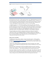
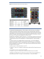
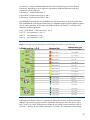
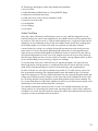
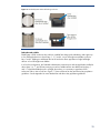
HP BladeSystem c3000 Enclosure
technology brief, 2nd edition
Abstract.............................................................................................................................................. 3
Overview of HP BladeSystem c3000 Enclosure ....................................................................................... 3
Managing the c3000 enclosure ............................................................................................................ 5
Onboard Administrator..................................................................................................................... 5
Detecting component insertion and removal..................................................................................... 5
Identifying components ................................................................................................................. 6
Managing power and cooling ....................................................................................................... 6
Controlling components................................................................................................................. 6
User interfaces for Onboard Administrator ...................................................................................... 8
Security ....................................................................................................................................... 8
Role-based user accounts............................................................................................................... 8
Integrated Lights-Out 2 for c-Class server blades .................................................................................. 9
Insight Display ................................................................................................................................. 9
Onboard Administrator cabling ....................................................................................................... 10
Enclosure link cabling ..................................................................................................................... 11
Enclosure-based DVD ROM................................................................................................................. 12
Enclosure KVM Module ...................................................................................................................... 12
Interconnect options and infrastructure.................................................................................................. 13
Interconnect modules ...................................................................................................................... 15
Server blades ................................................................................................................................ 16
Storage and other option blades...................................................................................................... 16
Mezzanine cards ........................................................................................................................... 17
Virtual Connect .............................................................................................................................. 18
Fabric connectivity and port mapping............................................................................................... 18
c3000 bay-to- bay crosslinks ........................................................................................................... 21
Device bay crosslinks.................................................................................................................. 21
Interconnect bay crosslinks .......................................................................................................... 22
HP Thermal Logic technologies ............................................................................................................ 22
Active Cool fans ............................................................................................................................ 23
HP PARSEC architecture.................................................................................................................. 24
Parallel...................................................................................................................................... 24
Redundant and scalable.............................................................................................................. 25
Thermal Logic for the server blade.................................................................................................... 26
Power supplies and enclosure power subsystem................................................................................. 27
Pooled power configuration and power redundancy options ........................................................... 29
Dynamic Power Saver mode ........................................................................................................ 30
HP Power Regulator for ProLiant ................................................................................................... 31
Power Capping for each server blade........................................................................................... 31
Power meter .............................................................................................................................. 31
HP BladeSystem Power Sizer ....................................................................................................... 31
Summary .......................................................................................................................................... 32
Appendix. Fan, power supply, and device bay population guidelines...................................................... 33
For more information.......................................................................................................................... 38
Call to action .................................................................................................................................... 38
2
Abstract
The HP BladeSystem c3000 Enclosure is the next generation in an evolution of the entire rackmounted infrastructure. The c3000 enclosure is designed for remote sites, small and medium-sized
businesses, and data centers with special power and cooling constraints. This technology brief
provides an overview of the HP BladeSystem c3000 Enclosure, Thermal Logic power and cooling
technologies, and interconnect options.
This technology brief assumes the reader is familiar with HP ProLiant server technology and has some
knowledge of general BladeSystem architecture. For more information about the infrastructure
components, see the HP website at www.hp.com/go/bladesystem/.
Overview of HP BladeSystem c3000 Enclosure
The HP BladeSystem c3000 Enclosure, announced in September 2007, is the newest enclosure
implemented using the BladeSystem c-Class architecture. While the c7000 enclosure is optimized for
enterprise data center applications, the c3000 enclosure is optimized for other computing
environments such as remote sites or small businesses. More information on c-Class architecture and
the c7000 enclosure is available on the HP technology website at www.hp.com/servers/technology.
The c3000 enclosure is available in two different models, the c3000 rack model that fits into standard
size HP and third-party racks, and the c3000 Tower model, which works well in sites without racks
(Figures 1 and 2). Both models employ c-Class form-factor server blades, storage blades, and
interconnect modules. The c3000 enclosure is optimized for particular computing environments such
as remote sites, retail stores, small offices, oil platforms, ships, planes, trucks, or any site with limited
power options. The c3000 enclosure is also designed for sites that may not have any special cooling
capability, and can exist in environments of up to 35 degrees centigrade. The c3000 enclosure is
designed for use with management devices such as local KVM switches for local administration.
Figure 1. HP BladeSystem c3000 Enclosure – front view
3
Figure 2. HP BladeSystem c3000 Enclosure – rear view
The HP BladeSystem c3000 Enclosure has redundant signal paths between servers and interconnect
modules. 1 The NonStop signal midplane in the c3000 enclosure has no active components. The
enclosure is available with a single-phase power subsystem that can run on either low-line or high-line
power. Both c3000 models can be populated with the following components:
• Up to four full-height (FH) or eight half-height (HH) server and/or storage blades per enclosure
• Up to four interconnect modules simultaneously supporting a variety of network interconnect fabrics
such as Ethernet, Fibre Channel (FC), InfiniBand (IB), Internet Small Computer System Interface
(iSCSI), or Serial-attached SCSI (SAS)
• Active Cool fan kits for a maximum of six fans
• Up to six power supplies with either low-line or high-line power input 2
• Onboard Administrator (OA) management module
• DVD drive
• Optional KVM enclosure module for connecting the c3000 to an in-rack KVM switch or HP TFT
7600 Rack Mount Keyboard/Monitor
Both c-Class enclosures have common critical components such as servers, interconnects, mezzanine
cards, storage blades, power supplies, and fans. Table 1 lists components supported by the c3000
and c7000 enclosures.
The c3000 enclosure will soon support two Onboard Administrator management modules, providing a fully
redundant design.
2
Typically, only four power supplies are required, especially in sites where non-redundant AC input is
acceptable.
1
4
Table 1. Components supported by HP BladeSystem c-Class enclosures
Enclosure
c3000
c7000
Model
Rack (6U) or Tower
Rack (10U)
Blade orientation
Horizontal (rack)
Vertical
Vertical (tower)
Blades supported
8 HH , 4 FH, 6HH/1FH
16 HH, 8 FH
Interconnect bays
4
8
Power supplies
6 at up to 1200 watts each
6 at 2250 watts each
Active Cool fans
6
10
Enclosure KVM support
Yes
No
CD/DVD support
Enclosure-based available
External
OA support
Single (now)
Single or dual
Dual (future)
Midplane speed
Tested up to 10 Gbit on midplane
Tested up to 10 Gbit on midplane
OA Serial/USB connections
In front
In rear
Managing the c3000 enclosure
The HP BladeSystem c3000 Enclosure has extensive embedded management capabilities based on
the Onboard Administrator, Integrated Lights-Out 2 (iLO 2) management processors integrated on the
server blades, and interconnect module management processors such as the HP Virtual Connect
Manager. Integrating all these management capabilities provides powerful hardware management for
remote administration, local diagnostics, and troubleshooting.
Onboard Administrator
The heart of c-Class enclosure management is the Onboard Administrator. The Onboard
Administrator module in the c3000 enclosure provides four services for the entire enclosure: detection,
identification, management, and control. There are three ways to access the Onboard Administrator:
web browser graphical user interface (GUI), scriptable command line interface (CLI), and the built-in
Insight Display diagnostic LCD panel included in the front of every c-Class enclosure.
Managing a c-Class enclosure involves multiple functions:
• Detecting component insertion and removal
• Identifying components and required connectivity
• Managing power and cooling
• Controlling components, including remote control and remote consoles
Detecting component insertion and removal
Onboard Administrator provides component control in c-Class enclosures. Component management
begins after the component is detected and identified. The Onboard Administrator detects
components in BladeSystem c-Class enclosures through presence signals on each bay. When a
component is inserted into a bay, the Onboard Administrator immediately recognizes and identifies
5
the component. If a component is removed from a bay, the Onboard Administrator deletes the
information about that component.
Identifying components
To identify a component, the Onboard Administrator reads a Field-Replaceable Unit (FRU) Electrically
Erasable Programmable Read-Only Memory (EEPROM) that contains specific factory information
about the component, such as product name, part number, and serial number. All FRU EEPROMs in
c-Class enclosures are always powered, even if the component is turned off, so the Onboard
Administrator can identify the component before granting power. For devices such as fans, power
supplies, and Insight Display, the Onboard Administrator reads the FRU EEPROMs directly. The
Onboard Administrator accesses server blade FRU EEPROMs through their iLO 2 management
processors.
The server blades contain several FRU EEPROMs: one on the server board which contains server
information and embedded NIC information and one on each of the installed mezzanine option
cards. Server blade control options include auto login to the iLO 2 web interface and remote server
consoles, virtual power control, and boot order control. Server blade control options also include
extensive server hardware information including BIOS and iLO 2 firmware versions, server name, NIC
and option card port IDs, and port mapping. The Onboard Administrator provides easy-to-understand
port mapping information for each of the server blades and interconnect modules in the enclosure.
The NIC and mezzanine option FRU information informs the Onboard Administrator of the type of
interconnects each server requires. Before granting power to a server blade, the Onboard
Administrator compares this information with the FRU EEPROMs on installed interconnect modules to
check for electronic keying errors. For interconnect modules, the Onboard Administrator provides
virtual power control, dedicated serial consoles, and management Ethernet connections, based on
which specific interconnect features are included.
Managing power and cooling
The most important Onboard Administrator tasks are power control and thermal management. The
Onboard Administrator can remotely control the power state of all components in BladeSystem c-Class
enclosures. For components in device bays in the front of each enclosure, the Onboard Administrator
communicates with iLO 2 to control servers and communicates with a microcontroller to control
options such as storage blades. A separate microcontroller controls power to interconnect modules.
Once components are granted power, the Onboard Administrator begins thermal management with
Thermal Logic. The Thermal Logic feature in the BladeSystem c3000 enclosure minimizes fan
subsystem power consumption by reading temperature sensors across the entire enclosure and
changing fan speed in different zones to minimize power consumption and maximize cooling
efficiency. More detailed information on Thermal Logic technologies follows later in this technology
brief.
Controlling components
The Onboard Administrator uses embedded management interfaces to provide detailed information
and health status for all bays in the enclosure (Figure 3). The Onboard Administrator also offers
information on firmware versions for most components in the enclosure and can be used to update
those components.
6
Figure 3. Management communications between Onboard Administrator and other components in an HP
BladeSystem c3000 Enclosure
c3000 internal management interfaces
The Onboard Administrator has several hardware interfaces to each bay in the c3000 enclosure to
provide management communications between the Onboard Administrator and all components in the
enclosure. The management hardware interfaces include unique presence pins, Inter-Integrated Circuit
(I2C), serial, and Ethernet connections. These management interface connections are completely
isolated from the server blade connections to interconnect modules.
c3000 external management interfaces
Each c3000 enclosure has several external management interfaces that connect the user to the
Onboard Administrator. The primary external management interface is the management port for the
Onboard Administrator, which is an RJ-45 jack providing Ethernet communications not only to the
Onboard Administrator, but also to every device or interconnect bay with a management processor.
This includes iLO 2 communication for the server blades and any interconnect module using the
c-Class embedded Ethernet management network, such as Virtual Connect Manager.
A serial port on the Onboard Administrator module provides full out-of-band CLI access to the
Onboard Administrator and is used for Onboard Administrator firmware flash recovery. USB ports on
the Onboard Administrator are used to connect external DVD drives to support the enclosure DVD
feature. In addition, an optional internal DVD drive is available for the c3000 enclosure. All c-Class
enclosures support two enclosure link connectors that provide private communications between
enclosures linked with CAT5 cable. In addition, the enclosure link-up connector provides an enclosure
7
service port that allows users to temporarily connect a laptop PC to any of the linked enclosure
Onboard Administrators for local diagnostics and debugging.
Updating firmware
The Onboard Administrator manages firmware updates for the enclosure’s management devices.
Updating firmware, including server BIOS firmware, NIC and mezzanine BIOS firmware, and iLO 2
firmware, is possible using HP System Update Manager or the blade firmware update maintenance
CD. These utilities can be connected to all the server blades in the enclosure using the Onboard
Administrator enclosure DVD feature. When the active Onboard Administrator detects that an external
USB DVD drive is installed in the internal DVD option or plugged into the USB port, it scans the DVD
drive for a CD or DVD disk. This disk can then be connected to one or more server blades using the
Onboard Administrator GUI, CLI, or Insight Display.
User interfaces for Onboard Administrator
Three user interfaces to the Onboard Administrator allow control and provide information about the
enclosure and installed components:
• Web browser GUI
• Scriptable OA CLI with optional KVM Module to access OA CLI
• Insight Display diagnostic LCD panel
Remote network access to the Onboard Administrator GUI and CLI is available through the
management Ethernet port. The Onboard Administrator serial port is available for local CLI access
and Onboard Administrator flash recovery. The c-Class enclosure link-up port is also available as the
service port for temporary local Ethernet access to the Onboard Administrators and devices in linked
enclosures.
Insight Display is accessed directly through the buttons on the display or remotely through the
Onboard Administrator GUI. The Optional KVM Module provides access to the Onboard
Administrator CLI through the external VGA monitor and USB keyboard.
Security
Security is maintained for all user interfaces through user authentication. User accounts created in the
Onboard Administrator define three user privilege levels and the component bays to which each level
is granted access. The Onboard Administrator stores the passwords for local user accounts and can
be configured to use Lightweight Directory Access Protocol (LDAP) authentication for user group
accounts. The Insight Display can be protected by an LCD PIN code or completely disabled. The
Optional KVM Module protects against changes to server power or enclosure DVD connection using
the LCD PIN code. Use of the KVM Module to access server consoles is protected by server operating
system username/passwords.
Role-based user accounts
The Onboard Administrator provides configurable user accounts that can provide complete isolation
of multiple administrative roles such as server, LAN and SAN. User accounts are configured with
specific device bay or interconnect bay permissions and one of three privilege levels: administrator,
operator, or user. An account with administrator privileges including Onboard Administrator bay
permission can create or edit all user accounts retained in an enclosure. Operator privileges allow full
information access and control of permitted bays. User privileges allow information access but no
control capability.
The Onboard Administrator requires user login to the web GUI or CLI with an account and password.
The account can be a local account where the password is stored on the Onboard Administrator, or
an LDAP account, where the Onboard Administrator contacts the defined LDAP server to check the
8
user credentials. Two-factor authentication allows even tighter security for the user management
session to the Onboard Administrator.
Rather than requiring separate logins to multiple resources (once to each enclosure and/or once to
every server management processor), the Onboard Administrator allows secure, single point access.
Thus, the administrator can use single sign-on to log in to a single Onboard Administrator and use the
web GUI to graphically view and manage the HP BladeSystem c-Class components in up to four
linked enclosures. For example, an IT administrator could automatically propagate management
commands—such as changing the enclosure power mode—throughout the linked enclosures.
More information about the Onboard Administrator is available in the technology brief entitled
“Managing the HP BladeSystem c-Class” at
http://h20000.www2.hp.com/bc/docs/support/SupportManual/c00814176/c00814176.pdf.
Integrated Lights-Out 2 for c-Class server blades
HP BladeSystem c-Class employs iLO 2 to configure, update, and operate individual server blades
remotely. The c3000 enclosure includes an Ethernet management network to aggregate all iLO 2
management communications across the entire enclosure. This management network connects iLO 2
processors to the Onboard Administrator through the Onboard Administrator tray. The Onboard
Administrator provides direct user access to each iLO 2 through the enclosure management network.
The Onboard Administrator uses this network to manage pooled enclosure power and cooling, which
results in substantial energy savings over the same number of individual rack-mounted servers.
Insight Display
The Insight Display (Figure 4) is an ever-ready, rack-mounted information exchange device with
access to all Onboard Administrator setup, management, and troubleshooting features. It is a quick
and easy-to-use device that allows the rack technician to initially configure the enclosure. It also
provides information about the health and operation of the enclosure. The Insight Display is effective
mechanically because it is big enough for the technician to see ample information, and it can slide
back and forth to allow access to the power supplies.
Figure 4. Insight Display on the c3000 enclosure
When the c3000 enclosure is initially powered on, the enclosure UID LED and the Insight Display are
illuminated blue to identify the enclosure being configured. The Insight Display automatically launches
an installation wizard to guide the user through the configuration process. After the enclosure is
9
configured, the Insight Display verifies that there are no installation or configuration errors. The
Installation Wizard turns off the enclosure UID when the installation is complete.
When an error or alert condition is detected, the Insight Display Health Summary screen displays the
total number of error conditions and their locations in the order of error severity (Figure 5). Failure
alerts (if any) are displayed first and then caution alerts are displayed. Providing this level of
diagnostic information for each enclosure dramatically shortens setup, repair, and troubleshooting
time.
For example, in Figure 5, the BladeSystem c-Class Insight Display diagnostic screen reports an error
in power supply bay 5. The device error reported on the Health Summary screen shows the power
supply in bay 5 as red. When the technician selects View Alert, the Device Error Summary screen
indicates the same condition. The Device Error detail in the third screen shows that the power supply
in bay 5 has failed. When the technician selects fix on the Device Error screen, suggestions for
corrective action appear.
Figure 5. BladeSystem c-Class Insight Display diagnostic screens indicating an error and suggested corrective
action
More information about the Insight Display is available in the technology brief entitled “Managing the
HP BladeSystem c-Class” at
http://h20000.www2.hp.com/bc/docs/support/SupportManual/c00814176/c00814176.pdf.
Onboard Administrator cabling
The standard Onboard Administrator module is preinstalled in a front-loading tray that also houses
the HP BladeSystem Insight Display. The Onboard Administrator module contains a serial connector
for connection to a PC with a null-modem RS232 serial cable. A USB connector is also available for
future USB connectivity. A separate rear-loading Onboard Administrator link module contains RJ-45
ports for enclosure link-up/link-down connectivity and Onboard Administrator network access
(Figure 6).
10
Figure 6. HP BladeSystem c3000 Onboard Administrator link module
Enclosure link cabling
The Onboard Administrator link module contains two enclosure link ports to allow any active
Onboard Administrator module to access linked enclosures. On a standalone enclosure or upper
enclosure in a series of linked enclosures, the upper enclosure link-up port functions as a service port
for temporary connection to a PC with a CAT5 patch cable. It provides quick access to any Onboard
Administrator module, iLO 2, or interconnect module with Ethernet management ability.
The enclosure link-down port connects to the enclosure link-up port on the enclosure below it. The
enclosure link-up port connects to the enclosure link-down port on the enclosure above it. Linking the
enclosures enables the rack technician to access all the enclosures through the open link-up/service
port. If more c-Class enclosures are added to the rack, they can be linked through the open enclosure
link-up port on the upper enclosure or the link-down port on the bottom enclosure.
NOTE
The enclosure link ports are designed only to support c-Class
enclosures in the same rack. The enclosure link-down port on the
upper enclosure is the service port. The enclosure link-down port
on the bottom linked enclosure is unused.
IMPORTANT
The HP BladeSystem c-Class Enclosure link ports are not
compatible with the HP BladeSystem p-Class Enclosure link
ports.
11
Enclosure-based DVD ROM
The HP BladeSystem c3000 Enclosure has an optional CD/DVD ROM drive that installs in the front of
the enclosure. The Insight Display and Onboard Administrator allow system administrators to connect
and disconnect the media device to one or multiple servers at a time. In addition, a browser-based
console is available through the iLO functionality of each server blade. The console enables
administrators to perform numerous options:
• Use HP SmartStart to install system software and operating systems
• Install additional software
• Perform critical OS updates and patches
• Update server platform ROMs
The enclosure-based CD/DVD offers local drive access to server blades by using the Onboard
Administrator or Insight Display. When media is loaded in the enclosure-based DVD ROM, local
administrators can use the Insight Display to attach the media device to one or multiple server blades
simultaneously. When the DVD Connect Status screen is displayed on the Insight Display, choosing to
connect the media device to a server or group of servers prompts the user to connect or to connect
and reboot the server.
When it is connected and no read operations have occurred in the previous 16 seconds, the media
device can be disconnected from server blades.
Enclosure KVM Module
Another option for the c3000 enclosure is the KVM Module, which plugs into the rear bay adjacent to
interconnect module 1 and provides a VGA connector and two additional USB connectors for the
c3000 enclosure. The VGA connector can be connected to an external VGA monitor and external
USB keyboard/mouse to provide access to all server video consoles, the Onboard Administrator
command line interface (CLI), or Insight Display. Using PrintScrn as a hot key to switch consoles, the
user can select a particular server console, control the server power, or connect to the enclosure DVD
from the KVM menu screen (Figure 7). In addition to allowing the user to select a server video
console, the menu provides current server health status, power status, and DVD connect status. Instead
of manually configuring a server name, the name is automatically provided by the Onboard
Administrator based on server information. From a server video console session, the user presses
PrintScrn to hot key back to the KVM menu. The Onboard Administrator CLI console provides a text
screen to log in and run command-line commands to the Onboard Administrator. The Insight Display
provides all the Insight Display screens for the enclosure on the KVM monitor and uses the KVM
keyboard to navigate those screens from the KVM station.
12
Figure 7. Optional c3000 KVM Module – KVM menu screen
Interconnect options and infrastructure
A key component of the c3000 enclosure is the I/O infrastructure—essentially, a NonStop signal
midplane that provides the internal wiring between the server or storage blades and the interconnect
modules. The NonStop signal midplane is an entirely passive board that takes advantage of
serializer/deserializer (SerDes) technology to support multiple protocols and provide point-to-point
connectivity between device bays and interconnect bays. The term passive means there are no active
electrical components on the board. BladeSystem enclosures easily enable connecting the ports of
embedded devices to the interconnect bays. The c3000 enclosure NonStop signal midplane
(Figure 8) acts as a PCI Express (PCIe) bus connecting interconnect ports on blade devices to
interconnect modules. It has eight device bay signal connectors (one for each half-height server blade
and two for each full-height server blade) and four interconnect module connectors (one for each
interconnect bay). The device connections are in groups of lanes. Each lane is a group of four pins
(two sending traces and two receiving traces), resulting in full-duplex communication. This
combination provides a 1x (500-Mb/s) transfer rate with 2x = 2 lanes (1-Gb/s).
13
Figure 8. Diagram of the HP BladeSystem c3000 signal midplane
By taking advantage of the similar four-wire differential transmit and receive mechanism, the NonStop
signal midplane can support either network-semantic protocols (such as Ethernet, Fibre Channel, and
InfiniBand) or memory-semantic protocols (PCIe), using the same signal traces. 3 Figure 9 illustrates
how the physical lanes can be logically overlaid onto sets of four traces. Interfaces such as Gigabit
Ethernet (1000-base-KX) or Fibre Channel need only a 1x lane, or a single set of four traces. Higher
bandwidth interfaces, such as InfiniBand DDR, use up to four lanes.
Network-semantic interconnect protocols use network addresses in the packet headers to exchange data
between two nodes such as MAC addresses and IP addresses for Ethernet, world-wide port name for FC, or
GUID for InfiniBand. Memory-semantic interconnect protocols use memory addresses in the packet headers to
deposit or retrieve data where these addresses can be memory-mapped registers of a chip or system memory
location.
3
14
Figure 9. Logically overlaying physical lanes (right) onto sets of four traces (left)
Each device bay connector has a 100-pin signal connector with 64 high-speed signal pins hard-wired
from the device bay connector to the interconnect bays. This configuration results in 16 lanes (64 ÷ 4)
to each interconnect bay, which provides at least two lanes to each interconnect port for connectivity
to LAN, storage area network (SAN), InfiniBand, or any other interconnect type. Full-height servers
occupy two half-height device bays and, therefore, have up to 32 lanes available.
A single lane supports up to 10-Gb signals, depending on the protocol requirement. Each lane
provides the flexibility of 1x, 2x, or 4x connections from the server blade mezzanine cards, which
provide connectivity to the interconnect bays. The rear of the enclosure includes four interconnect bays
that can accommodate four single or two redundant interconnect modules. All interconnect modules
plug directly into these interconnect bays. Each HP BladeSystem c3000 Enclosure requires two
interconnect switches or two pass-thru modules, side-by-side, for a fully redundant configuration.
The signal midplane also includes the management signals from each bay to the Onboard
Administrator modules. These management signals are completely isolated from the high-speed
server-to-interconnect signals. The Onboard Administrator is the terminating point for all interconnect
bays. An interconnect module cannot use the connection to the Onboard Administrator to
communicate with another interconnect module.
Interconnect modules
The BladeSystem c3000 enclosure supports a variety of interconnect options, including pass-thru
modules, Ethernet and Fibre Channel switches, and high-bandwidth fabrics such as InfiniBand. The
HP website (www.hp.com/go/bladesystem/interconnects) contains the most up-to-date information about
the c-Class interconnect modules.
Switches offer a traditional approach to administering the network. The primary value in blade
switches is cable consolidation through high-speed uplinks and the shared blade power and cooling
infrastructure.
Ethernet and Fibre Channel pass-thru modules are available when direct one-to-one connections
between servers and LAN or SAN are required. HP Ethernet and Fibre Channel Pass-Thru Modules
provide 16-port, transparent, 1:1 port connectivity between the server and an external switch.
Interconnect modules in the c3000 are available in two widths: single- and double-wide. Single-wide
interconnect modules provide sixteen internal ports, each connected to a separate device bay in the
front of the enclosure. Double-wide interconnect modules provide sixteen internal ports, each doublewide, providing connectivity to DDR Infiniband and other 4-lane high speed interconnects.
15
Each interconnect module also provides external connectors that vary based on the particular design.
In the c3000 enclosure, pairs of single-wide interconnect modules installed in adjacent horizontal
bays provide redundant connectivity for dual-port interfaces in each device bay. Adjacent
interconnect modules also have high-speed cross-connect capability through the enclosure’s NonStop
signal midplane.
NOTE
The c-Class Ethernet Pass-Thru Module only supports fixed speed
gigabit Ethernet. Because the server, storage, or other option
blades are connected through SerDes to the interconnect bays, and
SerDes Ethernet does not have an auto-negotiation protocol, a
switch is required to connect to 10/100 networks outside of the
enclosure. The NICs themselves are capable of different modes of
operation, but the outbound wiring to which they are connected is
not auto-negotiation friendly. Note that this is a limitation of an
Ethernet Pass-Thru Module only. The Fibre Channel Pass-Thru
Module ports do auto-negotiate.
Server blades
Server blades for the BladeSystem c3000 enclosure are built according to c-Class standard formfactors referred to as half-height and full-height. The enclosure can hold either full-height or half-height
server blades or a combination of the two.
For connectivity, every server ships with at least two built-in Ethernet connections. To maintain
flexibility, the server blades use optional mezzanine cards to provide additional interconnect fabric
connections such as Gigabit Ethernet, InfiniBand, and Fibre Channel.
Half-height server blades typically have two embedded Gigabit NICs and two c-Class PCIe
mezzanine option connectors. A half-height server configured with one dual-port Gigabit NIC
mezzanine card and one quad-port Gigabit NIC mezzanine card provides eight independent Gigabit
NICs. Full-height server blades typically have four embedded Gigabit NICs and three c-Class PCIe
mezzanine option connectors. A full-height server blade configured with three quad-port Gigabit NIC
mezzanine cards provides sixteen independent Gigabit NICs. The flexibility of c-Class design allows
customers to configure up to four different interconnect fabrics without sacrificing redundancy or
performance.
The HP website (www.hp.com/go/bladesystem/) contains the most up-to-date information about c-Class
server blades.
Storage and other option blades
Storage blades provide an alternative to internal disk drives or SAN connectivity. The c-Class
enclosure supports two types of storage blade solutions: direct-attach storage blades and shared
storage blades. For mechanical compatibility, storage blades use the same half-height form factor as
server blades. In addition to storage blades, tape and PCI option blades are available for c-Class.
Each of these option blades increases configuration flexibility by adding options that would not fit
inside the server blade.
A direct attach storage blade holds up to six SAS or SATA drives and must be paired with an
adjacent server blade in the same zone. This is because the physical connection between the direct
attach storage blade and its adjacent server blade is a dedicated x4 PCIe connection across the
NonStop midplane that connects the adjacent bays. The direct attach storage blade is equipped with
16
a Smart Array controller to enable hardware-based RAID configurations. A mezzanine card is not
required to connect a half-height server blade to a direct attach storage blade.
However, a full-height server blade does require a mezzanine card to connect to the direct attach
storage blade. The card must be in the Mezzanine 3 connector to allow full use of the interconnect
bays with Type I or Type II mezzanine cards, to be consistent with the half-height server blades, and
to enable mixing half-height and full-height server blades in the same enclosure. Additional options for
mezzanine cards are discussed in the following section.
NOTE
Because the direct attach storage blade must be in the bottom bay
when used with a full-height server blade, a blank must be
attached above the storage blade to block the empty upper bay, or
a half-height server blade must be inserted into the upper bay. For
the latter configuration, the storage blade should be installed
before the half-height server blade is installed, and the half-height
server blade should be removed before the storage blade is
removed.
HP also offers shared storage blades and shared storage arrays for the c3000 enclosure. Internal to
an enclosure, the HP StorageWorks All-in-One (AiO) SB600c shared storage blade requires two
adjacent half height device bays. The AiO SB600c shared storage device uses Windows Storage
Server, which can be configured as either file-based network-attached storage (NAS) or as blockbased iSCSI storage area network (SAN). The SB600c has approximately 1 TB of usable shared
storage capacity. The shared storage blade can be attached to server blades within or outside the
enclosure by using one or more Ethernet interconnect modules in the rear of the c3000 enclosure. The
Ethernet switches can be configured with iSCSI dedicated VLANs for isolating storage networks and
improving I/O performance.
The c3000 enclosure can also connect to a variety of external shared storage arrays and devices,
such as iSCSI, Fibre Channel, Serial Attached SCSI, and InfiniBand based storage arrays.
The most up-to-date information about the HP StorageWorks storage blade solutions is available at
http://h18004.www1.hp.com/products/blades/components/c-class-storageworks.html.
Mezzanine cards
HP offers a variety of mezzanine card options to provide connectivity to outside networks and
storage. HP ProLiant c-Class server blades use two types of mezzanine cards to connect to the various
interconnect fabrics such as Fibre Channel, Ethernet, serial-attached SCSI, or InfiniBand. Type I (x4)
and Type II (x8) mezzanine cards differ only in the amount of power allocated to them by the server
and in the physical space they occupy on the server blade. Type I mezzanine cards have slightly less
power available to them and are slightly smaller. Type I mezzanine cards are compatible with all
ProLiant c-Class server blades in all mezzanine connectors. Type II mezzanine cards are compatible
with Mezzanine 2 or 3 connectors in full-height c-Class server blades. Type II mezzanine cards are
also compatible with Mezzanine 2 connectors in half-height c-Class server blades.
NOTE
For all server blades other than the BL680c G5 and BL685c G5,
the InfiniBand 4x DDR single-port mezzanine card should be
placed in Mezzanine 2 or Mezzanine 3 connectors for maximum
performance. For the BL680c G5 and BL685c G5, the InfiniBand
17
4x DDR single-port mezzanine card will work equally well in
Mezzanine 1, Mezzanine 2, or Mezzanine 3 connectors.
Both types of mezzanine cards use a 450-pin connector, enabling up to eight lanes of differential
transmit and receive signals—in other words, up to two x1 connections, up to two x4 connections, or
a single x8 connection.
Because the connections between the device bays and the interconnect bays are hard-wired through
the signal midplane, the mezzanine cards must be matched to the appropriate type of interconnect
module. For example, a Fibre Channel mezzanine card must be placed in the mezzanine connector
that connects to an interconnect bay holding a Fibre Channel switch. To simplify installing various
mezzanine cards and interconnect modules, the Onboard Administrator uses an electronic keying
process to detect any mismatch between the mezzanine cards and the interconnect modules. The most
up-to-date information about c-Class mezzanine card options is available at
http://h18004.www1.hp.com/products/blades/components/c-class-interconnects.html.
Virtual Connect
With c-Class architecture, HP introduced a new type of interconnect technology: Virtual Connect. As it
is implemented in the c-Class architecture, Virtual Connect technology provides virtualized server I/O
connections to the Ethernet (LAN) or Fibre Channel (SAN) networks. Virtual Connect technology
virtualizes the server-edge so that networks can communicate with pools of HP BladeSystem servers
rather than in a conventional one-to-one relationship. HP recommends using Virtual Connect or
managed switches to reduce cabling and management overhead.
Virtual Connect consists of hardware (the Virtual Connect module) and firmware that runs on the
Virtual Connect module. Like other Ethernet and Fibre Channel switches, the Virtual Connect modules
slide into the switch bays of the c3000 enclosure. The Ethernet module is necessary to install Fibre
Channel because the Virtual Connect Manager software runs on a processor on the Ethernet module.
The Ethernet module has sixteen 1-GbE downlinks to servers (connected across the Nonstop signal
midplane), eight 1-GbE uplinks to the network (RJ45 copper Ethernet connectors), two 10-GbE
connectors (for copper CX4 cables), and one 10-GbE internal inter-switch link (across the NonStop
signal midplane) for a failover connection between Virtual Connect modules. The Fibre Channel
module has sixteen 4-Gb Fibre Channel downlinks to servers and four 1/2/4-Gb auto-sensing Fibre
Channel uplinks to the network.
Full details about Virtual Connect technology are available in the technology brief entitled “HP Virtual
Connect technology implementation for the HP BladeSystem c-Class”:
http://h20000.www2.hp.com/bc/docs/support/SupportManual/c00814156/c00814156.pdf.
Fabric connectivity and port mapping
Each enclosure requires interconnects to provide network access for data transfer. The interconnects
reside in interconnect bays located on the rear of the enclosure (Figure 10). The server blades and
enclosure support up to three independent interconnect fabrics, such as Ethernet, Fibre Channel,
InfiniBand, and Virtual Connect modules.
18
Figure 10. HP BladeSystem c3000 interconnect bay numbering
For interconnect bay mapping purposes, it does not matter in which device bay a server blade is
installed. The mezzanine connectors always connect to the same interconnect bays. Because the
connections between the device bays and the interconnect bays are hard-wired through the NonStop
signal midplane, the server mezzanine cards must be matched to the appropriate type of interconnect
module. For example, a Fibre Channel mezzanine card must be placed in the mezzanine connector
that connects to an interconnect bay holding a Fibre Channel switch.
Embedded NICs and adapters installed in Mezzanine 1 are supported by single-wide interconnects in
interconnect bays 1 and 2 respectively. Mezzanine 2 and 3 can be supported by either single-wide
or double-wide interconnects such as InfiniBand or 10 Gb Ethernet devices in interconnect bays 3
and 4.
An internal connection on the midplane between interconnect bays 1 and 2 and an additional
connection between interconnect bays 3 and 4 provide an internal link for use as a crosslink port
between interconnect bays 1 and 2 or interconnect bays 3 and 4. NIC teaming can be configured
between embedded NICs and Mezzanine 1 NICs using the internal crosslinks between the switches
through this internal connection.
Several port types are referenced in Figures 11 and 12:
• Examples of 1x ports are 1-Gb Ethernet (1-GbE) pass-thru modules and Fibre Channel interconnect
modules.
• An example of a 2x port is a SAS interconnect module.
• Examples of 4x ports are 10-GbE pass-thru modules and InfiniBand interconnect modules.
A full-height server blade plugs into two device bay connectors and has 32 lanes available to the 4
interconnect bays (16 lanes x 2 in Figure 12). Interconnect bay 1 is reserved for Ethernet
19
interconnects. It connects embedded Ethernet NICs to the internal facing ports on the Ethernet
interconnect. Depending on the configuration requirements, additional mezzanine cards and
interconnects can be employed:
• Mezzanine 1 and Interconnect Bay 2
• Mezzanine 2 and Interconnect Bays 3 and 4
• Mezzanine 3 and Interconnect Bays 3 and 4
The full-height server blade has four embedded NICs and can accept up to three mezzanine cards.
Each embedded NIC and optional mezzanine port is mapped through the signal midplane to specific
ports on interconnect bays. A full-height server blade installed in device bay 1 would have NICs
mapped in the following manner:
• NIC 1 (PXE default) — Interconnect bay 1 port 5
• NIC 2 — Interconnect bay 1 port 13
• NIC 3 — Interconnect bay 1 port 1
• NIC 4 — Interconnect bay 1 port 9
Figure 11. Port mapping for HP BladeSystem c3000 full-height server blades to interconnect bays
Half-height server blades connect to a single power and signal connector on the NonStop signal
midplane. The remaining signal connector is allocated to the adjacent device bay (that is, device
bays 1 and 5). As a result, half-height server blades do not support four-port mezzanine cards on
connector 1, and they do not contain a Mezzanine 3 connector. The extra lanes on the NonStop
20
signal midplane are allocated to the adjacent device bay. A four-port PCIe x8 mezzanine card
installed in connector 2 PCIe x8 can send x2 signals to interconnect bays 3 and 4.
Figure 12 lists the available configurations for half-height devices installed in device bay N (1–8).
Figure 12. Port mapping for HP BladeSystem c3000 half-height server blades to interconnect bays
Port mapping differs slightly between full-height and half-height server blades due to the support for
additional mezzanine cards on the full-height version. HP has simplified the process of mapping
mezzanine ports to switch ports by providing intelligent management tools through the Onboard
Administrator and HP Insight Manager software.
c3000 bay-to- bay crosslinks
For bay-to-bay communication, the c3000 midplane provides four-trace SerDes signals between
adjacent bays.
Device bay crosslinks
Device bay crosslinks are wired between adjacent horizontal device bay pairs as indicated by the
arrows in the c3000 enclosure front view (Figure 13). The crosslink connectivity is identical in the
c3000 Tower enclosure. For half-height server blades, these crosslinks are used for four-lane PCIe
connection to a partner blade such as a tape blade or PCI expansion blade. For full-height server
blades, these signals are used for PCIe connection to a partner blade in the lower adjacent bay and
require a PCIe pass-thru mezzanine card installed in mezzanine connector 3. The Onboard
Administrator disables the device bay crosslinks in instances where they cannot be utilized, such as
when two server blades reside in adjacent device bays.
21
Figure 13. HP BladeSystem c3000 device bay crosslinks as indicated by the arrows
Interconnect bay crosslinks
Interconnect bay crosslinks are wired between adjacent interconnect bay pairs as indicated by the
arrows in the c3000 enclosure rear view (Figure 14). The crosslink connectivity is identical in the
c3000 Tower enclosure. These signals can be enabled to provide module-to-module connections,
(such as Ethernet crosslink ports between matching switches) or they can be used by Virtual Connect
modules as stacking links. The Onboard Administrator disables the interconnect bay crosslinks in
instances where they cannot be used, such as when two different modules reside in adjacent
horizontal interconnect bays.
Figure 14. HP BladeSystem c3000 interconnect bay crosslinks indicated by the arrows
HP Thermal Logic technologies
The HP BladeSystem c3000 Enclosure incorporates a variety of HP Thermal Logic technologies,
including mechanical design features, built-in intelligence, and control capabilities. Thermal Logic
technologies provide significant power and cooling savings—as much as 40 percent compared to
traditional rack and tower based servers. Thermal Logic provides an instant view of power use and
temperature at the server, enclosure, or rack level. Thermal Logic automatically adjusts power and
thermal controls to minimize power and cooling use while maintaining adequate cooling for all
devices and ensuring high availability.
22
HP Thermal Logic technologies include many elements and capabilities:
• Active Cool fans
• Parallel Redundant Scalable Enclosure Cooling (PARSEC) design
• Instant power and thermal monitoring
• Pooled power for a variety of power redundancy modes
• Dynamic Power Saver mode
• Power Regulator
• Power Capping
• Power Meter
Active Cool fans
Quite often, dense, full-featured, small form-factor servers use very small fans designed to provide
localized cooling in the specific areas needed by the server blade. Because such fans generate fairly
low airflow (in cubic feet per minute, or CFM) at medium backpressure, a single server often requires
multiple fans to ensure adequate cooling. If each server blade contains several fans, installing many
server blades together in an enclosure can result in a significant cost and space overhead.
A second solution for cooling is to use larger, blower-style fans that can provide cooling across an
entire enclosure. Such fans are good at generating high-volume airflow, but they typically require
higher power input and must be designed for the maximum load in an enclosure. They also take up
more space and generate more noise. As a result, designers may have to sacrifice server features to
allow the large, high-power fans to fit in the enclosure. Even then, ensuring adequate airflow to all the
servers without leakage, over provisioning, or bypass is a challenge.
To overcome these issues in the c3000 enclosure, HP engineers designed a new type of fan that
delivers high airflow and high pressure in a small form factor that can scale to meet future cooling
needs. HP has 20 patents pending for its Active Cool fan technology and its implementation.
HP Active Cool fans can cool eight server blades using as little as 100 watts of power. Active Cool
fans use ducted fan technology with a high-performance motor and impeller (Figure 15) to deliver
high CFM at high pressure. The fan includes a bell mouth inlet with a specially designed impeller and
a stator section that also provides cooling fins for the motor and acoustic treatments at the rear of the
fan. This design provides cooling capacity to support blade products beyond current roadmaps. The
fan’s unique shape allows for high-volume, high-pressure airflow at even the slowest fan speeds, while
maintaining low noise levels and minimal power consumption.
The Onboard Administrator controls the Active Cool fans. The Onboard Administrator can ramp
cooling capacity up or down based on system needs, optimizing airflow, acoustic levels, and power
consumption. As a result, the c3000 enclosure requires less airflow than traditional rack-mount servers
to properly cool the server blades within the enclosure.
23
Figure 15. Ducted fan cross-section and ducted fan blade compared to traditional server fan
HP PARSEC architecture
The c3000 enclosure uses PARSEC architecture—parallel, redundant, scalable, enclosure-based
cooling. In this context, parallel means that fresh, cool air flows over all the server blades (in the front
of the enclosure) and all the interconnect modules (in the back of the enclosure). The enclosure is
divided into four cooling zones with fans in each. The Active Cool fans provide cooling for their own
zone and redundant cooling for the rest of the enclosure. To ensure scalability, HP designed both the
fans and the power supplies with enough capacity to meet the needs of compute, storage, and I/O
components well into the future.
Parallel
To optimize thermal design, HP developed a relatively airtight center air plenum, or air chamber. In
the c3000 enclosure, all device bays include a shutoff door that is normally closed to prevent air
leakage through that device bay into the center air plenum. When a server blade is inserted, it seals
into the plenum docking collar, and the server shutoff door opens to allow airflow across that server
blade. Similarly, Active Cool fans seal into the center air plenum docking collar. Each fan bay
includes louvers that automatically open when a fan is installed. If a fan is not installed or is not
functional, the pressure distribution around the fan changes. This pressure change causes the louvers
to close, ensuring that cool air is not diverted through the inoperative fan (Figure 16).
24
Figure 16. HP BladeSystem c3000 self-sealing enclosure
Redundant and scalable
BladeSystem c3000 enclosures ship with four installed fans that provide redundancy and support up
to four half-height devices in device bays 1, 2, 5, and 6, or two full-height server blades in device
bays 1 and 2. Adding two additional fans to the enclosure allows population of eight half-height
devices or four full-height server blades.
In a four-fan configuration, the Onboard Administrator prevents server and storage blades installed in
device bays 3, 4, 7, and 8 from powering on until two additional fans are added into fan bays 1
and 3. To populate blade devices in all eight device bays, it is necessary to populate c3000
enclosures with six Active Cool fans. Figure 17 shows enclosure fan bay and device bay population
guidelines. See the Appendix for more detailed fan and device bay population guidelines.
25
Figure 17. The c3000 enclosure fan bay and device bay population guidelines
Thermal Logic for the server blade
Precise ducting on HP server blades manages airflow and temperature based on the unique thermal
requirements of all the critical components. The airflow is tightly ducted to ensure that no air bypasses
the server blade and to obtain the most thermal work from the least amount of airflow. This concept
allows much more flexibility in heat sink design. The heat sink design closely matches the server blade
and processor architecture requirements. For example, in the HP BladeSystem BL460c server blade
using Intel® Xeon® processors, HP was able to use a smaller, high-efficiency processor heat sink than
in rack-mount servers. These heat sinks have vapor chamber bases, thinner fins, and tighter fin pitch
than previous designs. This creates the largest possible heat transfer surface in the smallest possible
package (Figure 18). The smaller heat sink allows more space on the server blades for full-size DIMM
sockets and hot-plug hard drives.
26
Figure 18. Processor heat sink using fully ducted design (left) and a traditional heat sink in a 1U rack-mount
server (right)
Instant Thermal Monitoring provides a real-time view of heat, power, and cooling data. The Onboard
Administrator retrieves thermal information from all server blades, storage blades, and interconnect
modules in the enclosure to ensure an optimal balance between cooling, acoustic levels, and power
consumption. The Thermal Logic feature of the Onboard Administrator keeps fan and system power at
the lowest level possible. However, if the thermal load within the enclosure increases, the Thermal
Logic feature instructs the fan controllers to increase fan speeds to accommodate the additional
demand. If high temperature levels occur, the iLO 2 and Onboard Administrator modules provide
alerts to various management tools such as HP Insight Control Environment for BladeSystem and HP
Systems Insight Manager. In addition, built-in failsafes shut down devices in the enclosure if
temperature levels exceed specified parameters. This protects against permanent damage to all
devices within the enclosure.
HP Thermal Logic includes sophisticated algorithms in each BladeSystem ROM, iLO, and Onboard
Administrator. In combination, these algorithms minimize the power and cooling required to maintain
the proper HP BladeSystem environment.
Power supplies and enclosure power subsystem
The HP BladeSystem c3000 Enclosure ships with two power supplies; however, up to six power
supplies can be installed (Figure 19) depending on the AC redundancy level required and the number
of devices installed in the enclosure. BladeSystem c3000 single-phase power supplies automatically
switch between low-line (120VAC) and high-line (240 VAC) to support both environments. A pooled
power backplane delivers power to the enclosure. This ensures that the full capacity of the power
supplies is available to all server blades.
Moving the power supplies into the enclosure reduced the transmission distance for DC power
distribution, allowing the use of an industry-standard 12V infrastructure. Using a 12V infrastructure
eliminated several power-related components and improved power efficiency on the server blades
and in the infrastructure. The control circuitry was stripped and put on the management board and
fans.
27
Figure 19. HP BladeSystem c3000 Enclosure supports up to six power supplies
High efficiency HP c3000 power supplies provide greater than 90 percent efficiency in AC to DC
conversion. These power supplies use the ProLiant universal form factor so they can also be used in
other ProLiant servers. Each power supply ships with a standard power distribution unit (PDU) power
cord (C13 to C14), and each enclosure includes c13 to c20 power cords for different types of PDUs.
By purchasing proper wall outlet cords, users can connect the power supplies to standard wall outlets.
CAUTION
Wall outlet power cords should only be used with low-line
power sources. If high-line power outlets are required, safety
regulations require either a PDU or a UPS between the c3000
enclosure power supplies and wall outlets.
The enclosure can contain up to six 1200-watt self-cooled power supplies. Most typically, the c3000
enclosure would be deployed at sites that would not normally have datacenter AC redundancy to
racks. Therefore, the c3000 has been configured so that only four power supplies are needed in a
Power Supply Redundant (N+1) mode, where the enclosure would be connected to a UPS, or a single
PDU, or directly into 110V wall outlets. If there is a need for dual AC power feeds and datacenterlike AC Redundancy, 6 power supplies can be configured to connect to a pair of PDUs (three
connected to each PDU). A variety of PDUs are available, as indicated in the c3000 QuickSpecs:
http://h18004.www1.hp.com/products/quickspecs/12790_div/12790_div.html. The HP BladeSystem
Power Sizer is a tool for sizing the PDU appropriately for the c3000 storage and server
configuration. 4
HP expects that in many of the markets targeted for the c3000 enclosure (midmarket and remote
sites), the c3000 will be connected to an uninterruptible power supply (UPS) for power backup
instead of to a PDU (Figure 20). HP recommends using HP BladeSystem Power Sizer to determine the
number of power supplies needed in the c3000 and to determine the UPS capacity requirement.
4
See the For more information section at the end of this document for a link to the HP BladeSystem Power Sizer.
28
Figure 20. Remote site solution includes a c3000 enclosure with UPS and local KVM in a small 14U rack
NOTE
The rack-mountable HP R5500 UPS (5000VA/4500W)
supports four power supplies in the power supply redundant
(N+1) power mode.
Pooled power configuration and power redundancy options
All the power in the enclosure is provided as a single power pool that any server blade within the
enclosure can access. This provides maximum flexibility when configuring the power in the system so
that customers can choose the required enclosure power mode. Because this power design has no
zones, it facilitates both N+N and N+1 power modes, which future-proofs the enclosure for higher
power requirements, if needed. Looking forward at least five years, HP believes there is sufficient
power capacity to handle future power-hungry devices.
The c3000 enclosure has three configurable redundancy modes: power supply redundant, AC
redundant, and no redundancy mode. The Onboard Administrator or the Insight Display can be used
to select the power redundancy mode. For more information, consult the HP BladeSystem Onboard
Administrator User Guide:
http://h20000.www2.hp.com/bc/docs/support/SupportManual/c00705292/c00705292.pdf.
Typical power configuration connecting to UPS, wall outlets, or a single non-redundant PDU (using
Power Supply redundancy mode)
In a configuration with N+1 power supply redundancy connecting to a UPS (Figure 21), wall outlets,
or to a single non-redundant PDU, the total power available equals the total power available less one
power supply. Up to six power supplies can be installed and one of them is always available to
provide redundancy. In the event of a single power supply failure, the redundant power supply will
take over the load of the failed power supply.
29
Figure 21. Redundant HP BladeSystem c3000 power supplies connected to an HP R5500 UPS
Connecting to PDUs with AC redundancy to each rack
In an N+N AC redundancy configuration, the total power available in the power pool equals the
amount from the A or B side, whichever contains fewer power supplies. In this configuration, N power
supplies are used to provide power, and the same number are used to provide redundancy. N can
equal 1, 2, or 3. Any number of power supplies from 1 to N can fail without causing the enclosure to
lose power. When correctly wired with redundant AC line feeds, this configuration will also ensure
that a single AC line feed failure will not cause the enclosure to power off.
Connecting with no power redundancy configured
In a configuration with no power redundancy, the total power available in the power pool equals the
sum of the power generated by all installed power supplies. Any power supply failure will cause the
system to power off if the remaining power supplies are unable to handle the full load.
The Onboard Administrator manages power allocation rules of various components and can limit
overall power capacity for the enclosure. More information on power management is available in the
technology brief entitled “Managing the HP BladeSystem c-Class”:
http://h20000.www2.hp.com/bc/docs/support/SupportManual/c00814176/c00814176.pdf.
Dynamic Power Saver mode
In the c3000, the Onboard Administrator module enables Dynamic Power Saver. When enabled, this
feature monitors the total power consumed by the enclosure in real-time and automatically adjusts for
changes in demand. For example, most power supplies operate more efficiently when heavily loaded
and less efficiently when lightly loaded. Dynamic Power Saver mode shifts power load for maximum
power supply efficiency and reliability. Maximizing power supply efficiency reduces operating costs.
Power supply efficiency is simply a measure of DC watts output divided by AC or DC watts input. At
50 percent efficiency, 2000W input would yield 1000W output. The difference is costly wasted
energy that generates unnecessary heat.
Dynamic Power Saver mode is active by default since it saves power in the majority of situations.
When enabled, Dynamic Power Saver runs the required power supplies at a higher use rate and puts
unneeded power supplies in standby mode. A typical power supply running at 20 percent load could
have an efficiency rating as low as 60 percent. However, at 50 percent load, the efficiency rating
could be up to 90 percent, providing a significant savings in power consumption.
30
NOTE
In redundant environments using Dynamic Power Saver mode, a
minimum of two power supplies are always active. The
maximum load for any power supply is 50 percent. Once the
50 percent load is reached, another two power supplies are
activated to ensure redundancy at all times.
HP Power Regulator for ProLiant
HP Power Regulator for ProLiant and BladeSystem servers provides iLO-controlled speed stepping for
Intel x86 and recent AMD processors to improve server energy efficiency by giving processors full
power when they need it and reducing power when they do not. This power management feature
allows ProLiant servers with policy-based power management to control processor power states.
Power Regulator can be configured for continuous Static Low Power mode or for Dynamic Power
Savings mode in which power is automatically adjusted to match processor demand. Additional
information on the HP Power Regulator is provided in the paper, “Power Regulator for ProLiant
servers”: http://h20000.www2.hp.com/bc/docs/support/SupportManual/c00593374/c00593374.pdf.
Power Capping for each server blade
Using HP Power Capping, iLO 2 firmware version 1.30, and System ROM/BIOS dated May 1,
2007, or later, IT administrators can limit power consumption by HP BladeSystem c-Class server
blades. Customers can set a power cap in watts or BTUs per hour. This cap constrains the amount of
power consumed, which reduces heat output into the data center. The iLO 2 firmware monitors server
power consumption, checks it against the power cap goal, and, if necessary, adjusts server
performance to maintain an average power consumption that is less than or equal to the preset power
cap. This functionality is available on all ProLiant server blades using Intel or recent AMD processors.
Using the Insight Power Manager (IPM) v1.10 plug-in to HP Systems Insight Manager v5.1, IT
administrators can set power caps on groups of supported servers. The IPM software statically
allocates the group power cap equitably among the servers in the group. The allocation is based on a
calculation using the idle and maximum measured power consumption of each server. IPM can track
and graph over time the actual power use of groups of servers and enclosures. Availability of data on
measured power consumption for various time periods reduces the need to install monitored PDUs to
measure actual power use in data centers.
Power meter
In HP ProLiant c-Class server blades, an integrated power meter analyzes actual server power use.
The Onboard Administrator can access the power meter through iLO 2 or through external power
management software such as HP IPM. IPM also consolidates power data for multiple servers to a
central location. This information can be used to charge business units or third parties for the actual
energy costs associated with workload processing. The Onboard Administrator provides instant and
time-averaged views of the power consumption of individual servers or of all servers within the c-Class
BladeSystem enclosure.
HP BladeSystem Power Sizer
The HP BladeSystem Power Sizer is a tool that assists facilities teams and IT staff in sizing their power
and cooling infrastructures to meet the needs of an HP BladeSystem solution. The BladeSystem Power
Sizer is based on actual component-level power measurements of a system stressed to maximum
capability. The sizer allows customers to select the type and number of components within each server
blade and enclosure so they can see the effect of changes on power consumption and heat loading.
Values obtained from the BladeSystem Power Sizer tool are based on worst-case loads and are
intended for facility planning purposes only. Actual power consumption will vary with application
31
type, application utilization, and ambient temperature. The BladeSystem Power Sizer is available at
the following URL: http://www.hp.com/go/bladesystem/powercalculator.
Summary
The HP BladeSystem c3000 Enclosure is the next generation of a new modular computing architecture
that consolidates and simplifies infrastructure, reduces operational cost, and delivers IT services more
effectively. The c3000 enclosure is designed for remote sites, small and medium-sized businesses, and
data centers with special power and cooling constraints. Thermal Logic technologies provide the
mechanical design features, built-in intelligence, and control capabilities throughout the BladeSystem
c-Class that enable IT administrators to optimize the power and thermal environments. The shared,
high-speed NonStop midplane and pooled-power backplane in the enclosure accommodate new
bandwidths and new technologies. The Onboard Administrator supplies an intelligent infrastructure to
provide essential power and cooling information and to help automate infrastructure management.
The BladeSystem c3000 enclosure provides all the power, cooling, and infrastructure to support
c-Class modular servers, interconnects, and storage components, today and throughout the next
several years.
32
Appendix. Fan, power supply, and device bay population
guidelines
Figure A-1. Fan population guidelines for HP BladeSystem c3000 Enclosure. For correct operation, fans and
server blades must be installed in the correct fan bays. The Onboard Administrator will ensure that fans and
server/storage blades are correctly placed before allowing systems to power on.
BladeSystem c3000 enclosures ship with four fans installed, supporting up to four half-height devices
or two full-height server blades. Adding two more fans to the enclosure allows population with eight
half-height or four full-height devices:
• Four-fan configuration requires population of fan bays 2, 4, 5, and 6.
• Six-fan configuration enables population of all fan bays.
In a four-fan configuration, the Onboard Administrator prevents blade devices in device bays 3, 4, 7,
and 8 from powering on and identifies the fan subsystem as degraded. To incorporate blade devices
in these device bays, install six Active Cool fans.
33
Figure A-2. Power supply population guidelines for HP BladeSystem c3000 Enclosure
Table A-1. Power supply placement for HP BladeSystem c3000 Enclosure
Number of power supplies
Power supply bays used
2
1 and 4
4
1, 2, 4, and 5
6
All power supply bays filled
Table A-2. Power supply redundancy options for HP BladeSystem c3000 Enclosure
Number of power supplies
Power supply bays used
1+1
1 and 4
2+1
1, 4, and 2
3+1
1, 4, 2, and 5
4+1
1, 4, 2, 5, and 3
5+1
Populate all power supply bays
Table A-3. AC redundancy options for HP BladeSystem c3000 Enclosure
Number of power supplies
Power supply bays used
1+1
1 and 4
2+2
1, 2, 4, and 5
3+3
Populate all power supply bays
34
Figure A-3. Full-height server blade device bay numbering for HP BladeSystem c3000 Enclosure. Full--height
servers should be populated from bottom to top (rack) or left to right (tower) when viewing from the front of the
enclosure. With four fans, only the bottom or left two device bays can be used; with six fans, all device bays can
be used.
Figure A-4. Half-height server blade device bay numbering for HP BladeSystem c3000 Enclosure. Half--height
servers should be populated in the following order: Device bays 1, 5, 2, 6, 3, 7, 4, 8.
IMPORTANT
When looking at the rear of the enclosure, device bay
numbering is reversed.
35
CAUTION
To prevent improper cooling or thermal damage, do not operate
the server blade or the enclosure unless all device bays are
populated with either a component or a blank.
Figure A-5. The c3000 enclosure is divided by sheet metal panels into two full-height zones. Zone 1 and Zone 2
are divided in half by a removable shelf to accommodate a maximum of eight half-height device bays per
enclosure. These zones reflect the PCIe bus mapping in the signal midplane and limit placement of the server
blade/storage blade combination. The signal midplane has a direct PCIe link connecting adjacent paired device
bays.
.
IMPORTANT
The server blade/storage blade relationship cannot extend beyond
the removable dividers between full height device bays, nor can it
span the removable bay shelf dividing the zone into half-height
device bays.
The enclosure comes preinstalled with removable full-height dividers between the four device bays in
Zone 2 and the four device bays in Zone 1. In addition, a half-height divider is available for use
between device bays 4 and 8 if the full-height divider is removed. Using these combinations of
dividers, the following combinations of server blades can be installed:
• Eight half-height server blades with both full-height dividers installed
• Four full-height server blades with both full-height dividers removed
• Four half-height server blades in Zone 1 with one full-height divider installed
• Two full-height server blades in Zone 1 with one full-height divider removed
• Four half-height server blades in Zone 2 with one full-height divider installed
• Two full-height server blades in Zone 2 with one full-height divider removed
• One full-height server blade and two half-height server blades in Zone 2 with one full-height divider
removed and the half-height divider installed
36
CAUTION
If a full-height server blade is installed in device bay 1/5 and
half-height server blades are installed in device bays 2 or 6,
removing the full-height server blade leaves server blades
installed in device bays 2 and 6 unsupported. This might cause
damage to the server blades and the enclosure connectors.
Removing the full-height divider in Zone 1 allows only full-height server blades to be installed in
Zone 1.
Removing the full-height divider in the Zone 2 requires either installing only full-height server blades in
Zone 2 or installing the half-height divider between device bays 4 and 8. With the half-height divider
installed, two half-height devices (two server blades, one companion blade and one server blade, or
one blade blank and one companion blade or server blade) can be installed in device bays 4 and 8,
and one full-height server blade in device bay 3/7.
A companion blade (HP StorageWorks SB40c Storage Blade, HP PCI Expansion Blade, or HP
StorageWorks Ultrium 448c Tape Blade) can be installed in either of the paired device bays (1/2,
3/4, 5/6, or 7/8) with a half-height server blade installed in the other paired device bay.
To install a companion blade with a full-height server blade, the companion blade must be installed in
device bay 8 with the full-height server blade installed in device bay 3/7. The half-height divider must
be installed between device bays 4 and 8, and either a blade blank or a half-height server blade can
be installed in device bay 4.
37
For more information
For additional information, refer to the resources listed below.
Resource description
Web address
General HP BladeSystem information
http://www.hp.com/go/bladesystem/
HP BladeSystem c-Class
documentation
http://h71028.www7.hp.com/enterprise/cache/316735-0-0-0121.html
HP BladeSystem c3000 Enclosure
Maintenance and Service Guide
http://h20000.www2.hp.com/bc/docs/support/SupportManual/
c01126895/c01126895.pdf
HP BladeSystem c3000 Enclosure
QuickSpecs
http://h18004.www1.hp.com/products/quickspecs/12790_div/1
2790_div.html
HP BladeSystem Onboard
Administrator User Guide
http://h20000.www2.hp.com/bc/docs/support/SupportManual/
c00705292/c00705292.pdf
HP BladeSystem c-Class interconnects
www.hp.com/go/bladesystem/interconnects
Technology briefs about HP
BladeSystem
http://h18004.www1.hp.com/products/servers/technology/white
papers/proliant-servers.html
HP BladeSystem Power Sizer
http://www.hp.com/go/bladesystem/powercalculator
HP BladeSystem c-Class firmware
compatibility matrix
http://www.hp.com/go/bladesystemupdates
iLO 2 firmware updates
http://www/hp.com/go/ilo
Server software and drivers
http://welcome.hp.com/country/us/en/support.html
Insight Power Manager software
http://www.hp.com/go/ipm
Call to action
Send comments about this paper to [email protected].
© 2007, 2008 Hewlett-Packard Development Company, L.P. The information
contained herein is subject to change without notice. The only warranties for HP
products and services are set forth in the express warranty statements
accompanying such products and services. Nothing herein should be construed as
constituting an additional warranty. HP shall not be liable for technical or editorial
errors or omissions contained herein.
Intel and Xeon are trademarks or registered trademarks of Intel Corporation in the
U.S. and other countries and are used under license.
TC080601TB, June 2008