1
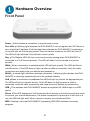
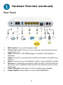
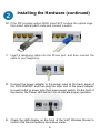
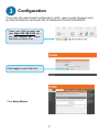
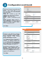
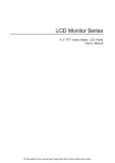
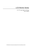
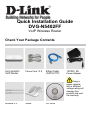
Quick Installation Guide
DVG-N5402FF
VoIP Wireless Router
Check Your Package Contents
DVG-N5402FF
VoIP Router
Phone Cord X 2
Ether Cable
(CAT5 UTP)
12VDC, 2A
Power Adapter
Using a
power adapter
with a different
voltage rating will
damage this
product and void
the warranty.
Antenna X 2
Stand
CD-ROM
Hardware Overview
Front Panel
Power:Solid indicates a connection to a good power source.
Prov./Alm:A blinking light indicates the DVG-N5402FF can not register with SIP Server or
can not get the IP address. A blinking light also indicates the DVG-N5402FF is attempting
to connect with the Provisioning server. Once the service connects, the LED will turn off.
The LED will light solid red if the self-test or boot-up fails.
Reg.:The Register LED will turn on and continuously working when DVG-N5402FF is
connected to a VoIP service provider. The LED will flash if not connected to a service
provider.
WAN:When a connection is established the LED will light up solid. The LED will blink to
indicate activity. If the LED does not light up when a cable is connected, verify the cable
connections and make sure your devices are powered on.
WLAN:A steady light indicates a wireless connection. A blinking light indicates that DVGN5402FF is receiving/ transmitting from/to the wireless network
LAN:When a connection is established the LED will light up solid on the appropriate port.
The LEDs will blink to indicate activity. If the LED does not light up when a cable is
connected, verify the cable connections and make sure your devices are powered on.
USB:This indicates that DVG-N5402FF detects a supported 3G USB dungle or a USB
device.
Phone:This LED displays the VoIP status and Hook activity on the phone port that is used
to connect your normal telephone(s). If a phone connected to a phone port is off hook or in
use, this LED will light solid. When a phone is ringing, the indicator will blink.
WPS: Flashing in blue as DVG-N5402FF processing WPS-PBC wireless connecting
progress.
2
Hardware Overview (continued)
Rear Panel
1.
2.
3.
4.
5.
6.
7.
8.
WiFi Switch: Turn on/off wireless LAN.
Phone Port (1-2): Connect to your phones using standard phone
cabling (RJ-11).
USB: Connect to a 3G USB dungle or a printer.(This feature is
optional.)
LAN: Connect to your Ethernet enabled computers using Ethernet
cabling.
WAN: Connect to your broadband modem using an Ethernet cable.
Ground: A conducting connection with the earth. Connect with the
ground so as to make the earth a part of an electrical circuit using
metal wire.
Power Receptor: Receptor for the provided power adapter.
Power Switch: Press down to turn-on DVG-N5402FF.
3
Hardware Overview (continued)
1.
2.
3.
WPS: WPS button for wireless WPS-PBC setup method.
Antenna: Connect to antenna for wireless network.
Reset: Keep pressing 6 seconds to restore DVG to be factory
default.
Installing the Hardware
A. Insert one end of the Ethernet cable into the Ethernet (LAN) port on
the back panel of the DVG-N5402FF and the other end of the cable
to an Ethernet Adapter or available Ethernet port on your computer.
B. Insert one end of the Ethernet cable into the WAN port on the back of
the DVG-N5402FF and the other into your cable/DSL modem or the
LAN port of your router.
4
Installing the Hardware (continued)
B1. If the ISP provides optical WAN, insert SFP module into optical cage
then insert optical patch code.and connect a switch.
C. Insert a telephone cable into the Phone port, and then connect the
cable to your telephone.
D. Connect the power adapter to the power input at the back panel of
the DVG-N5402FF and then plug the other end of the power adapter
to a wall outlet or power strip then press power switch. On the front of
the device, the Power LED will turn On to indicate proper operation.
E. Check the LED display on the front of the VoIP Wireless Router to
confirm that the connections have been made.
5
Installing the Hardware (continued)
After the installations are completed, your network should look similar to
the diagram below.
Hardware configuration is complete! If your VoIP service is already activated, you
can make phone calls now.
6
Configuration
To access the web-based configuration utility, open a web browser such
as Internet Explorer and enter the IP address of the DVG-N5402FF.
Open your Web browser and
type http://192.168.8.254 into
the URL address box. Press
the Enter or Return Key.
Click Login to enter Web Site.
Click Setup Wizard.
7
Configuration (continued)
Click Next.
The username of ADMIN and USER
have been defined and locked by
default. It is highly recommended to
create a login password to keep
your router secure.
Click Next.
Enter a NTP server or use the
default server.
Click Next.
8
Configuration (continued)
Select your Internet connection type:
DHCP – Most Cable ISPs or if you
are connecting the DVG-N5402FF
behind a router.
Static IP – Select if your ISP
supplied you with your IP settings.
PPPoE – Most DSL ISPs.
PPTP – Select if required by your
ISP.
WAN1 Domain Name Server –
Select Manual to manually enter IP
address of DNS or select Auto if
DNS is assigned by ISP.
Click Next.
Register to the SIP Proxy Server
by clicking Enable support of SIP
Proxy Server. Enter Proxy
Server IP/Domain and Port.
The Outbound Proxy Support is
optional. To register, please click
on the Outbound Proxy Support
check box and enter Outbound
Proxy IP/Domain and Port in it.
Registration by phone line: enter
Number, User ID/Account and
Password supplied by your ITSP.
Click on the Register check box to
register to Proxy Server.
Click Next.
9
Configuration (continued)
Click on the Enable wireless LAN
interface check box to build a
wireless network. Enter the SSID to
name your wireless network. All
devices must have the same SSID
to communicate on the wireless
network. Select a wireless channel.
Select the 802.11 Mode of your
network which can work in different
speed of wireless connection.
Click Next.
Select your wireless security modes
for your wireless network.
Click Next
Setup is finished. Check the
summary of your settings. To
make new settings effective, you
must click on the Restart button
to reboot the DVG-N5402FF.
Click Restart.
10
Technical Support
You can find software updates and user documentation
on the D-Link website.
Tech Support for customers within United States:
D-Link Technical Support over the Telephone:
(800)326-1688
D-Link Technical Support over the Internet:
http://support.dlink.com
email:[email protected]
11
Ver. 1.00 (WW)
2011/06/27