1
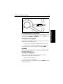
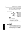
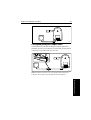
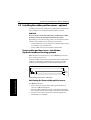
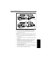
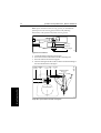
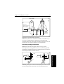
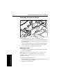
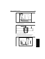
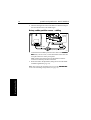
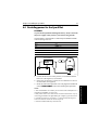
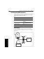
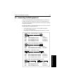
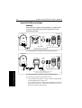
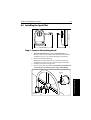
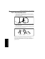
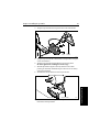
SportPilot and
SportPilot Plus
Owner’s
Handbook
Document number: 81057-5
Date: May 2001
ii
SportPilot and SportPilot Plus - Owner’s Handbook
Autohelm, HSB (High Speed Bus), SailPilot, SeaTalk and SportPilot
are registered trademarks of Raymarine Ltd.
Raymarine, AST (Advanced Steering Technology), AutoAdapt,
AutoLearn, AutoRelease, AutoSeastate, AutoTack, AutoTrim,
FastTrim, GyroPlus, RayGyro, RayPilot and WindTrim are
trademarks of Raymarine Ltd.
Handbook contents © Raymarine Ltd 2001.
Preface
iii
Contents
Chapter 1: Introduction ............................................................1
About this handbook ................................................................. 3
Important Information .............................................................. 3
Chapter 2: Operating the SportPilot .......................................9
2.1 Switching on and off ................................................................. 9
Switching on ............................................................................. 9
Switching off ............................................................................. 9
2.2 Basic operation ......................................................................... 9
Engaging and disengaging the pilot .......................................... 9
Making course changes ........................................................... 10
Adjusting autopilot gain .......................................................... 11
2.3 Using Navigator (Track) mode ............................................... 12
Chapter 3: Maintenance & Fault Finding ..............................15
3.1 General maintenance .............................................................. 15
3.2 Fault finding ............................................................................ 16
3.3 Product support ....................................................................... 16
Chapter 4: Installing the SportPilot ......................................19
4.1 Planning the installation .......................................................... 20
Installation instructions ........................................................... 21
4.2 Installing the compass ............................................................. 23
Compass location .................................................................... 23
Compass mounting ................................................................. 24
Compass cabling ..................................................................... 24
4.3 Installing the rudder position sensor – optional ...................... 26
Linear rudder position sensor – installation (hydraulic outboard
steering systems) ..................................................................... 26
Rotary rudder position sensor – installation (hydraulic inboard
steering systems) ..................................................................... 29
4.4 Providing power for the SportPilot ......................................... 37
Interfacing with NMEA equipment ........................................ 38
4.5 Connecting SeaTalk equipment .............................................. 39
Typical SeaTalk connections .................................................. 40
4.6 Installing the SportPilot .......................................................... 41
Step 1 – Remove the steering wheel ........................................ 41
Step 2 – Mount the torque bracket ........................................... 42
Step 3 – Plug the cables into the SportPilot ............................. 45
Step 4 – Assemble and secure the SportPilot .......................... 47
iv
SportPilot and SportPilot Plus - Owner’s Handbook
Chapter 5: Compass Calibration ............................................51
Important note ......................................................................... 51
Introduction ............................................................................ 51
5.1 Compass linearization and heading alignment ....................... 52
5.2 Heading alignment without linearizing .................................. 54
Index ..................................................................................... 55
Chapter 1: Introduction
1
Chapter 1: Introduction
1 Introduction
D1356-2
Congratulations on the purchase of your Raymarine SportPilot.
The SportPilot fits neatly over the steering column directly behind the
steering wheel. All of the autopilot controls are located on a rotary
switch at the end of a control stalk. These controls consist of:
•
•
•
Standby mode (STANDBY)
five autopilot settings (LO to HI) to control the amount of rudder
applied when course changes are made
Navigator (or Track) mode (NAV) for tracking to waypoints when
the SportPilot is used with a chartplotter or GPS
The SportPilot is very easy to use:
•
•
simply point the boat in the direction you want to go, turn the
rotary control switch to one of the autopilot settings (LO to HI)
and release the wheel – it really is that simple
if you want to change course under autopilot control, simply turn
the boat onto the new heading and once again let go of the wheel –
you don’t even have to disengage the autopilot
If you have a SeaTalk or NMEA position sensor, navigation to
favorite fishing grounds or wrecks is a breeze. Cross track error
information is constantly fed to the autopilot so that your heading is
continuously updated.
2
SportPilot and SportPilot Plus - Owner’s Handbook
1 Introduction
The SportPilot can also be operated away from the steering station,
using a hand-held remote control or a Raymarine fixed control unit.
The SportPilot is designed to be owner installed, and most of the
necessary tools are supplied.
SportPilot and SportPilot Plus specifications
There are two versions of the SportPilot: the SportPilot and the
SportPilot Plus. It is vital to use the appropriate pilot for your boat.
The SportPilot will not perform effectively if you exceed the
following boat compatibility specifications.
General specifications
Nominal supply voltage:
12 V DC
Dimensions:
Height: 220 mm (8.7 in)
Width: 238.5 mm (9.4 in) including stalk
137.5 mm (5.4 in) excluding stalk
Depth: 100.5 mm (4.0 in)
Heading reference:
Raymarine fluxgate compass
Operating modes:
• Standby (autopilot not active)
• Auto (autopilot operating): with five settings to
control autopilot rudder gain.
• Navigation (Track) mode: autopilot following
waypoints received from navigator.
Inputs/Outputs:
Compass, Rudder Position Sensor,
Power/NMEA 0183, SeaTalk
Steering shaft size:
19 mm (3/4 in) and 25 mm (1in) tapered
SportPilot – boat compatibility
Maximum displacement:
2000 kg (4400 lbs) manual cable steering
3500 kg (7700 lbs) manual hydraulic steering
3500 kg (7700 lbs) servo hydraulic steering
Maximum wheel diameter: 54 cm (21 in) wooden
(depending on weight)
46 cm (18 in) metal
SportPilot Plus – boat compatibility
The SportPilot Plus has a more powerful motor designed specifically for boats
where the autopilot is used for hours at a time on a daily basis.
Chapter 1: Introduction
3
About this handbook
This handbook contains two main parts:
This part of the handbook explains how to use your SportPilot:
2
Chapter 2: Operating the SportPilot
Explains how to use the SportPilot.
page 9
3
Chapter 3: Maintenance & Fault Finding
Provides maintenance and fault finding information.
page 15
Part 2: Installing the SportPilot
This part of the handbook explains how to install your SportPilot:
4
Chapter 4: Installing the SportPilot
Explains how to install your SportPilot and its components.
page 19
5
Chapter 5: Compass Calibration
Explains how to linearize the SportPilot compass and align
its heading.
page 51
Note: This handbook contains important information about
installing, using and maintaining your new Raymarine product. To
get the best from the product, please read this handbook thoroughly.
Important Information
Warranty
To register your new Raymarine product, please take a few minutes to
fill out the warranty card. It is important that you complete the owner
information and return the card to us to receive full warranty benefits.
Handbook information
To the best of our knowledge, the information in this handbook was
correct when it went to press. However, Raymarine cannot accept
liability for any inaccuracies or omissions it may contain. In addition,
our policy of continuous product improvement may change
specifications without notice. As a result, Raymarine cannot accept
liability for any differences between the product and the handbook.
1 Introduction
Part 1: Using the SportPilot
4
SportPilot and SportPilot Plus - Owner’s Handbook
Safety notices
1 Introduction
WARNING:
Product installation
This equipment must be installed and operated in accordance
with the instructions contained in this handbook. Failure to do so
could result in poor product performance, personal injury
and/or damage to your boat.
WARNING:
Electrical safety
Make sure the power supply is switched off before you make any
electrical connections.
WARNING:
Navigation aid
Although we have designed this product to be accurate and
reliable, many factors can affect its performance. As a result, it
should only be used as an aid to navigation and should never
replace common sense and navigational judgement. Always
maintain a permanent watch so you can respond to situations as
they develop.
Your Raymarine autopilot will add a new dimension to your boating
enjoyment. However, it is the skipper’s responsibility to ensure the
safety of the boat at all times by following these basic rules:
•
•
•
•
•
•
Ensure that someone is present at the helm AT ALL TIMES, to
take manual control in an emergency.
Make sure that all crew members know how to disengage the
autopilot.
Regularly check for other boats and any obstacles to navigation –
no matter how clear the sea may appear, a dangerous situation can
develop rapidly.
Maintain an accurate record of the boat’s position by using either
a navigation aid or visual bearings.
Maintain a continuous plot of your boat’s position on a current
chart. Ensure that the locked autopilot heading will steer the boat
clear of all obstacles. Make proper allowance for tidal set – the
autopilot cannot.
Even when your autopilot is locked onto the desired track using a
navigation aid, always maintain a log and make regular positional
plots. Navigation signals can produce significant errors under
some circumstances and the autopilot will not be able to detect
these errors.
Chapter 1: Introduction
5
EMC conformance
1 Introduction
All Raymarine equipment and accessories are designed to the best
industry standards for use in the recreational marine environment.
The design and manufacture of Raymarine equipment and
accessories conform to the appropriate Electromagnetic
Compatibility (EMC) standards, but correct installation is required to
ensure that performance is not compromised.
1 Introduction
6
SportPilot and SportPilot Plus - Owner’s Handbook
Part 1: Using the SportPilot
Part 1:
Using the
SportPilot
Part 1: Using the SportPilot
Chapter 2: Operating the SportPilot
9
Chapter 2: Operating the SportPilot
2.1 Switching on and off
Switching on
The SportPilot enters Standby mode when the power supply is
switched on. This mode is identified by the flashing red AUTO LED.
As soon as the pilot is engaged (see below), the red LED glows
permanently to confirm this selection.
Switching off
2.2 Basic operation
Engaging and disengaging the pilot
Engaging the pilot
1. Steer the boat onto the required heading.
2. Turn the rotary control switch clockwise from STANDBY to one
of the five autopilot gain settings (LO to HI).
Note: It is important to select the correct gain setting for your
boat’s speed. See page 11 for details.
3. Release the wheel – there will be a short delay before the pilot
takes control.
D1400-2
2 Operating the SportPilot
Switching off your boat’s power supply will switch off the SportPilot.
To prevent the SportPilot draining the battery, always switch off
the power supply when leaving the boat for long periods.
10
SportPilot and SportPilot Plus - Owner’s Handbook
Disengaging the pilot
You can disengage the SportPilot at any time by turning the rotary
control switch to STANDBY.
Making course changes
Large course changes
2 Operating the SportPilot
When your boat is under autopilot control, you can override the pilot
at any time by steering the wheel in the normal way.
As soon as you release the wheel, the SportPilot automatically
regains control to maintain the boat’s current heading.
CAUTION:
You MUST center the helm after making large course changes. If
you do not center the helm, the autopilot could become unstable
or take a long time to settle onto the required heading.
Minor course changes
When your boat is under autopilot control, you can make minor
course adjustments in 1° increments by pressing the:
•
•
-1° (Port) or
+1° (Starboard) switches on top of the control stalk
D1403-2A
Note: You can also make course changes using an optional handheld
remote control or repeater autopilot control unit (if fitted).
Chapter 2: Operating the SportPilot
11
Adjusting autopilot gain
The autopilot gain setting determines the amount of rudder the pilot
applies during course change. Autopilot gain is relative to the speed
of your boat.There are five available gain settings on the SportPilot:
•
•
•
LO: lowest gain setting
three mid-range positions
HI: highest gain setting
LO gain
HI gain
D1402-2
Setting the gain for your boat
WARNING:
It is vital that the autopilot gain control is set correctly – an
incorrect setting will lead to poor steering performance and can
produce violent course changes at high speed.
The ideal gain setting for one boat may not be ideal for another, so
finding the correct setting for your boat will be down to
experimentation and experience. The following HI and LO setting
details are general guidelines only.
HI gains
Generally, low boat speeds require a medium to HI setting to provide
better course keeping.
WARNING:
This setting is not recommended for high speeds as it may cause
some instability and, therefore, could be dangerous.
LO gains
Most high speed boats will require a medium to LO setting. This
provides the greatest stability.
2 Operating the SportPilot
Mid-range gain
12
SportPilot and SportPilot Plus - Owner’s Handbook
Automatic gain correction
Autopilot gain is automatically adjusted if the SportPilot is
connected to either a:
•
•
SeaTalk instrument transmitting boat speed through the water or
boat speed over the ground, or
NMEA instrument transmitting NMEA 0183 boat speed through
the water or boat speed over the ground
2 Operating the SportPilot
Initially set the control stalk to the gain position most suited to your
boat. The SportPilot will then automatically adjust the gain (up or
down) from this setting as your boat speed changes.
Note: The SportPilot must receive boat speed information via
SeaTalk or NMEA to automatically adjust the gain.
2.3 Using Navigator (Track) mode
The SportPilot can automatically steer to a waypoint using
information from any SeaTalk navigator or NMEA 0183 compatible
GPS. Alternatively, the SportPilot can follow a route defined on a
SeaTalk Navcenter or GPS.
004
002
003
001
D1410-2
Entering Navigator (Track) mode
To enter Navigator mode so you follow a route of waypoints:
1. Create or select a route of waypoints on the navigator.
2. Engage the pilot and steer your boat onto the first waypoint
bearing (within 0.3 nm of track).
3. Press in the end of the control stalk to enter Navigator (Track)
mode. The yellow NAV light glows to confirm this selection.
Chapter 2: Operating the SportPilot
13
Exiting Navigator (Track) mode
To exit Navigator (Track) mode and return to Standby mode, turn the
end of the control stick back to STANDBY. The yellow NAV light will
go out and the red AUTO light will flash.
Turning to next waypoint
In Navigator (Track) mode, the SportPilot automatically determines
the direction to the target waypoint:
•
•
if a turn to port is required, the SportPilot emits 2 short beeps
if a starboard turn is needed, the SportPilot emits 1 short beep
To accept the turn, press in the end of the control stalk (NAV).
CAUTION:
Before you accept a turn to port or starboard, ALWAYS make
sure that it is safe to do so.
Arriving at a waypoint
When you arrive at a target waypoint, the SportPilot requests
permission to advance to the next waypoint:
•
•
two short beeps for a port turn
one short beep for a starboard turn
Make sure that it is safe to make the turn, then press NAV to advance
to the next waypoint.
2 Operating the SportPilot
D1358-2
14
SportPilot and SportPilot Plus - Owner’s Handbook
Safety points
The SportPilot can only follow a user defined route if the navigation
equipment transmits all of the following information:
•
•
•
bearing to waypoint (BTW)
cross track error (XTE)
waypoint number
2 Operating the SportPilot
If cross track error (XTE) is the only available information, the
SportPilot will advance to the next waypoint without requesting
permission. In this case, you should always manually steer the boat to
within 15° of the new bearing to waypoint before you press NAV.
Audible alarms in Navigator mode
The SportPilot emits the following audible warning alarms in
Navigator (Track) mode:
Audible alarm
Reason
2 short beeps
Turn to port required
1 short beep
Turn to starboard required
2 short and 1 long beep
Off course
Continuous short beeps
Track problem (large XTE, no data or data error)
Chapter 3: Maintenance & Fault Finding
15
Chapter 3: Maintenance & Fault Finding
This chapter provides information about maintaining your SportPilot
system, obtaining product support and solving common problems.
3.1 General maintenance
CAUTION:
The SportPilot and fluxgate compass do not contain any user
serviceable parts. These products should be serviced only by
authorized Raymarine service technicians.
Routine cabling checks
•
•
Make sure all connections are firmly attached.
Examine the cables for signs of wear or damage – replace any
damaged cables.
Cleaning the SportPilot
If the SportPilot is dirty, wipe it with a clean, damp cloth.
Never use chemical or abrasive materials to clean the SportPilot.
EMC advice
•
•
•
•
When powered up, all electrical equipment produces
electromagnetic fields. These can cause adjacent pieces of
electrical equipment to interact with one another, with a
consequent adverse effect on operation.
To minimize these effects and enable you to get the best possible
performance from your Raymarine equipment, guidelines are
given in the installation instructions, to enable you to ensure
minimum interaction between different items of equipment, i.e.
ensure optimum Electromagnetic Compatibility (EMC).
Always report any EMC-related problems to your nearest
Raymarine dealer. We use such information to improve our
quality standards.
In some installations, it may not be possible to prevent the
equipment from being affected by external influences. In general
this will not damage the equipment but it can lead to spurious
resetting action, or momentarily may result in faulty operation.
3 Maintenance & Fault Finding
•
•
16
SportPilot and SportPilot Plus - Owner’s Handbook
3.2 Fault finding
All Raymarine products are designed to provide many years of
trouble-free operation. We also put them through comprehensive
testing and quality assurance procedures before shipping.
3 Maintenance & Fault Finding
In the unlikely event that a fault does occur with your autopilot, use
the following table to help identify the problem and provide a
solution. If you cannot resolve the problem yourself, refer to the
product support information below.
SYMPTOM
CAUSE
SOLUTION
SportPilot does not
power up.
Power connection at
the power supply or
SportPilot.
Make sure that all
connections are
secure.
Blown fuse or circuit
breaker.
Replace fuse or circuit
breaker.
Over-active heading
correction.
Autopilot gain too
high.
Turn control stalk
towards LO gain.
Poor course keeping.
Autopilot gain too low.
Turn control stalk
towards HI gain.
Over-active heading
correction or poor
course keeping after
adjusting the gain.
Pre-programmed
settings not suitable
for your boat.
Contact your nearest
Raymarine dealer.
If a rudder position
sensor is connected:
the SportPilot may not
have sensed its
presence.
Auto-sensing can take
up to 10 minutes.
During this time you
may experience poor
course-keeping.
Compass heading
alignment incorrect.
Complete the heading
alignment procedure
(see page 52)
NAV (Track) mode:
SportPilot steers onto
wrong bearing after you
accept the turn alarm.
3.3 Product support
Raymarine products are supported by a worldwide network of
distributors and Authorized Service Representatives. If you
encounter any difficulties with this product, please contact either
your national distributor, service representative, or the Raymarine
Technical Services Call Center. Refer to the back cover or the
Worldwide Distributor List for contact details.
Part 2:
Installing the
SportPilot
Part 2: Installing the SportPilot
Part 2: Installing the SportPilot
Chapter 4: Installing the SportPilot
19
Chapter 4: Installing the SportPilot
Introduction
The SportPilot fits neatly over your boat’s existing steering shaft with
the steering wheel bolted directly onto the pilot. The unit can
accommodate either 3/4 in (19 mm) or 1 in (25 mm) steering shaft
tapers using a simple adaptor collar (supplied).
All installations require an external fluxgate compass (supplied) to
feed the SportPilot with precise heading information. This unit plugs
directly into the rear of the pilot. It should be mounted in a central
location to minimize the effects of pitching and rolling.
If your boat has a hydraulic helm pump, you must also fit a rudder
position sensor. You will need to use either a linear or rotary rudder
sensor, depending on your boat’s steering system (see page 26).
The sections in this chapter explain how to install and connect the
components of your SportPilot system:
Planning the installation
page 20
4.2
Installing the compass
page 23
4.3
Installing the rudder position sensor –
optional
page 26
4.4
Providing power for the SportPilot
page 37
4.5
Connecting SeaTalk equipment
page 39
4.6
Installing the SportPilot
page 41
4 Installing the SportPilot
4.1
20
SportPilot and SportPilot Plus - Owner’s Handbook
4.1 Planning the installation
Steering boss parts
Raymarine woodruff key
Steering boss
Adaptor collar
M4 x 12mm screw
and washer (x4)
Retaining nuts (3/8in, 1/2in, 5/8in)
and washers (M12 x 1, M16 x 2)
Torque restraint parts
Bracket
template
SportPilot/SportPilot Plus
Front
M4 x 40 mm bolt
and washer
Power cable
Fluxgate
compass
Back
Bracket
No8 x 3/4 in
countersunk screw (x4)
Cable holder parts
Optional:
M3 x 8 mm
screw (x2)
Cable holder
Cable sealing mat
Rotary or
linear rudder
position
sensor and
fittings
Compass
warning label
3.4mm drill bit
4 Installing the SportPilot
No8 x 3/4in self-tapping
pan-head screws (x4)
SportPilot and
SportPilot Plus
Owner's
Handbook
Owner's Handbook
Box spanner
(15/16 in and 3/4 in)
3mm allen key
Worldwide
Distributors
Worldwide Distributor List
Quick Reference Card
D1406-2
Chapter 4: Installing the SportPilot
21
Installation instructions
Before you start installing your SportPilot system, use the illustration
to check the parts supplied. Then read through the following
information and the relevant installation sections in this chapter.
Cabling guidelines
•
•
•
consider how you will run cables to and from each component
avoid running cables through bilges where possible
avoid running cables close to fluorescent lights, engines, radio
transmitting equipment etc.
EMC suppression ferrites
We supply the fluxgate compass and power cables with suppression
ferrites fitted. Always use these ferrites supplied by Raymarine.
D3548-2
During installation you should position these ferrites as close as
possible to the SportPilot, just behind the bulkhead. You may need to
remove the ferrites during installation. If you do so, you MUST
reassemble them around the cable when installation is complete.
Suppression ferrite
D3106-2
4 Installing the SportPilot
Bulkhead
22
SportPilot and SportPilot Plus - Owner’s Handbook
EMC installation guidelines
All Raymarine equipment and accessories are designed to the best
industry standards for use in the recreational marine environment.
Their design and manufacture conforms to the appropriate
Electromagnetic Compatibility (EMC) standards, but correct
installation is required to ensure that performance is not compromised.
Although every effort has been taken to ensure that they will perform
under all conditions, it is important to understand what factors could
affect the operation of the product.
The guidelines given here describe the conditions for optimum EMC
performance, but it is recognized that it may not be possible to meet
all of these conditions in all situations. To ensure the best possible
conditions for EMC performance within the constraints imposed by
any location, always ensure the maximum separation possible
between different items of electrical equipment.
For optimum EMC performance, we recommend that:
•
•
4 Installing the SportPilot
•
•
Raymarine equipment and cables connected to it are:
• At least 3 ft (1 m) from any equipment transmitting or cables
carrying radio signals e.g. VHF radios, cables and antennas.
In the case of SSB radios, increase the distance to 7 ft (2 m).
• More than 7 ft (2 m) from the path of a radar beam. A radar
beam can normally be assumed to spread 20 degrees above
and below the radiating element.
The equipment is supplied from a separate battery from that used
for engine start. Voltage drops below 10 V, and starter motor
transients, can cause the equipment to reset. This will not damage
the equipment, but may cause the loss of some information and
may change the operating mode.
Raymarine specified cables are used. Cutting and rejoining these
cables can compromise EMC performance and must be avoided
unless doing so is detailed in the installation manual.
If a suppression ferrite is attached to a cable, this ferrite should not
be removed. If the ferrite needs to be removed during installation
it must be reassembled in the same position.
Connections to other equipment
If your Raymarine equipment is to be connected to other equipment
using a cable not supplied by Raymarine, a suppression ferrite MUST
always be attached to the cable near to the Raymarine unit.
Chapter 4: Installing the SportPilot
23
4.2 Installing the compass
The compass contains a self-levelling mechanism. This enables the
compass to provide accurate readings with pitch and roll movements
up to +/- 35°.
Note: The rattle that the fluxgate compass makes when shaken is
normal. It is caused by the pendulum weight hitting the inside of
the case.
76 mm (3 in)
76 mm (3 in)
D5381-1
Fluxgate compass dimensions
Compass location
To achieve the best performance from the compass, mount it:
•
•
•
•
With the Raymarine logo facing the bow.
Note: If it is not possible to install the fluxgate compass with
the logo facing the bow, you must complete the Compass
Calibration procedures (see Chapter 5:Compass Calibration).
As close as possible to the boat’s pitch and roll center.
At least 0.8m (2ft 6in) away from your boat’s steering compass to
avoid deviation of both compasses.
As far away as possible from large iron masses, such as the engine
or other magnetic devices.
4 Installing the SportPilot
D1522-2
24
SportPilot and SportPilot Plus - Owner’s Handbook
Note: To check if the intended mounting location is free from
magnetic influence, tape a handheld compass to the chosen location,
then turn the boat through 360°. The readings on the handheld
compass and your boat’s main steering compass (if accurately
aligned) should not differ by more than10° at any heading.
Compass mounting
Ver
t
ica
l
D5384-1
CAUTION:
You must mount the fluxgate compass on a vertical bulkhead,
with the cable exiting at the base.
1.
2.
3.
4.
Hold the compass against the mounting location.
Mark the four mounting holes, then remove the compass.
Drill four pilot holes using a 3 mm (1/8 in) drill bit.
Making sure the cable exits at the bottom of the compass, secure
the fluxgate compass using the self-tapping screws provided
(No 8 x 3/4 in, pan-head).
4 Installing the SportPilot
Note: Stick the supplied warning label near to the compass, where it
is clearly visible.
Compass cabling
1. Route the cable to the steering station, taking into account the
EMC installation guidelines (page 22).
2. Secure the cable at regular intervals with suitable cable clips/ties.
Note: You will plug the moulded connector into the COMPASS
socket when installing the SportPilot (see page 45). You will also
need to attach the supplied suppression ferrite behind the bulkhead
as close as possible to the SportPilot.
Chapter 4: Installing the SportPilot
25
D1515-2
Cutting and joining the compass cable
You should not cut and rejoin the fluxgate compass cable unless
absolutely necessary. If you do have to cut the cable, use Scotchlock
connectors to re-join the wires color for color.
D1544-2a
Note: Scotchlock connectors are not supplied with the Fluxgate
Compass. These must be purchased from your local dealer.
4 Installing the SportPilot
26
SportPilot and SportPilot Plus - Owner’s Handbook
4.3 Installing the rudder position sensor – optional
A rudder position sensor will improve your SportPilot’s performance
by providing precise information about the rudder’s position.
CAUTION:
If your boat has a hydraulic helm pump, you MUST fit a rudder
position sensor for the SportPilot to function accurately.
Depending on your boat’s steering system, you will need to use either
a linear or rotary rudder sensor. Generally, you will need:
•
•
a linear rudder sensor if your boat has an outboard engine steered
by a ‘bullhorn’ style hydraulic ram
a rotary rudder sensor if your boat has an inboard ram.
Linear rudder position sensor – installation
(hydraulic outboard steering systems)
Note: Hydraulic outboard steering systems MUST be fitted with a
linear rudder position sensor.
The linear rudder position sensor (part number: Z229) is designed for
‘bullhorn’ style hydraulic outboard steering systems. It is totally
weatherproof and designed to be mounted on the bullhorn ram.
425 mm (16.75 in)
32 mm
(1.3 in)
D5389-1
4 Installing the SportPilot
Linear rudder position sensor – dimensions
Positioning the linear rudder position sensor
You MUST ensure that:
•
•
•
there is equal travel of the sensor shaft to port and starboard
(as shown by A on the diagram)
the sensor shaft is parallel to the ram – if the shaft is not parallel,
the U-bracket could be driven off the ram when the shaft extends
the sensor is clear of any obstructions when the engine(s) are
turned hard-over or tilted up
Chapter 4: Installing the SportPilot
27
A
Equal travel
port and starboard
B
Un-equal travel
port and starboard
D1676-2
Mounting the linear rudder position sensor
1. Use the steering system to position the bullhorn ram amidships.
2. If necessary, release the hydraulic pressure from the boat’s
hydraulic steering system
Note: Contact your steering gear manufacture for advice on this step,
and follow their instructions for releasing the hydraulic pressure.
4 Installing the SportPilot
3. Loosen the starboard bolt that secures the bullhorn ram’s shaft to
the end bracket.
4. Fit the U-bracket (supplied) over the end bracket and the bullhorn
ram’s shaft.
5. Hand tighten the starboard bolt to hold the U-bracket in place.
6. Fully open the hose clamps (supplied) using a flat bladed
screwdriver, then hang them over the bullhorn ram.
7. Place the spacers (supplied) on the bullhorn ram and use adhesive
tape to secure them temporarily.
8. Pull out the rudder sensor’s shaft until its alignment mark is level
with the end of the barrel.
9. Position the rudder sensor against the spacers so the threaded rod
end of its shaft passes through the U-bracket.
28
SportPilot and SportPilot Plus - Owner’s Handbook
10. Tighten the hose clamps around the bullhorn ram and the rudder
sensor’s barrel.
11. Tighten the starboard bullhorn bolt to secure the U-bracket.
12. Fit and tighten the supplied nut and washer to secure the threaded
rod end of the sensor’s shaft to the U-bracket.
Starboard
bolt
Nut and
washer
End
bracket
Bullhorn
ram shaft
Threaded
rod
U-bracket
Sensor
shaft
Sensor
shaft
Sensor
barrel
Alignment mark
Sensor
barrel
Cable
Hose clamp
Spacer
Bullhorn
ram
D5390-1
Notes: 1. If there is restricted space below the ram, you can mount the
sensor in front of the ram.
2. We recommend installing the sensor with its shaft pointing to
starboard. If you cannot install the unit in this orientation, you can fit
it with the shaft pointing to port. If you do this, the SportPilot will
automatically correct itself, so no manual adjustment is necessary.
4 Installing the SportPilot
Linear rudder position sensor – cabling
1. Connect the linear rudder position sensor cable to the RUDDER
REF cable (color for color). Use the Scotchlock connectors and
crimp the connectors with a pair of pliers.
Note: Connect the cables close to the SportPilot so that the
connectors remain dry and free from strain.
2. Route the cable to the SportPilot, taking into account the EMC
installation guidelines (page 21).
Note: To allow for the bullhorn’s movement, leave a loop of
cable at the end of the linear rudder position sensor.
Chapter 4: Installing the SportPilot
29
Note: You will plug the moulded connector into the RUDDER REF
socket when installing the SportPilot (see page 45).
Scotchlock
connector
RUDDER REF cable
Linear rudder position sensor cable
D1544-2
Post installation checks
When you have connected the sensor to your SportPilot, pressurize
the steering system (if required).
Note: Contact your steering gear manufacture for advice on this step.
Follow their instructions for re-pressurizing the hydraulic pressure.
Rotary rudder position sensor – installation
(hydraulic inboard steering systems)
140 mm (5.5 in)
60 mm (2.4 in)
187 mm (7.35 in)
D5386-1
Note: Hydraulic inboard steering systems MUST be fitted with a
linear rudder position sensor.
The rotary rudder position sensor can be used on hydraulic inboard
steering systems to transmit the precise position of the boat’s steering
to the SportPilot. Depending on your engine installation, you can
mount the sensor to the steering arm, or to the tie bar.
4 Installing the SportPilot
70 mm (2.75 in)
30
SportPilot and SportPilot Plus - Owner’s Handbook
Connecting the sensor to a steering arm
Rotary rudder
position sensor
Steering arm
Raymarine
steering pin
Engine
Power
steering
D1728-2
Typical installation – sensor connected to horizontal steering arm
Before you attempt to fit the sensor to a steering arm, please consider
the following points:
•
•
4 Installing the SportPilot
•
•
If the distance between the transom and the steering arm
attachment point is greater than 65 mm (2.5 in, it may be
necessary to mount the sensor on a fabricated base (e.g. a metal
bracket or block of wood). This ensures that the connecting rod is
at 90° to the center-line of the sensor and steering arms.
It may be necessary to relocate other equipment installed on the
transom.
Although the illustration shows the sensor arm pointing upwards,
if necessary the sensor can be installed so that the arm is pointing
towards the bottom of the boat.
Whichever way you install the transducer, the cable should
always exit the sensor base directly opposite the sensor arm.
CAUTION:
Before you start installing the rotary rudder position sensor,
make sure that you have a spare cotter/split pin available in case
the original is lost or cannot be used again.
Chapter 4: Installing the SportPilot
31
Mounting the sensor
1. With the steering amidships, align the sensor as shown in the
relevant illustration below:
UP
Sensor pin must
be level with
steering pin
Steering arm
Raymarine steering pin
Rudder position
sensor
Drive aperture
Parallel
Distance apart: 75 mm (3 in) min
310 mm (12.2 in) max
D1707-2
Single drive system with horizontal steering arm
UP
Steering arm
Rudder position
sensor
Power
steering
Sensor pin and
steering linkage
must be at
same height
Parallel
D1692-2
Single drive system with vertical steering arm
2. Use the three self-tapping screws to attach the sensor directly to
the transom (or a fabricated mounting base).
3. Remove the pin securing the steering arm to the power steering.
4. Fit the Raymarine steering pin and retain with a split/cotter pin.
4 Installing the SportPilot
Distance apart: 75 mm (3 in) min
310 mm (12.2 in) max
32
SportPilot and SportPilot Plus - Owner’s Handbook
Note: If your boat has a Volvo steering system, you should fit the
plastic spacer to the steering pin (as shown in the following
illustration) so the pin does not foul the steering system.
Plastic sleeve
Steering arm
Raymarine steering pin
D1991-2
Typical Volvo installation
5.
6.
7.
8.
Cut the threaded connecting rod to length.
Screw the lock nuts and sockets onto the connecting rod.
Press the sockets onto the steering pins.
Turn the steering from side to side to make sure that the linkage is
free from obstructions at all angles.
Power Steering
steering
arm
Socket
UP
Lock Connecting
nut
rod
Maximum permitted
travel = 120˚
90˚
4 Installing the SportPilot
Steering amidships
D1709-2
Single drive system with horizontal steering arm
Chapter 4: Installing the SportPilot
33
UP
Steering amidships
Dimension A
optimum: 140 mm (5.5 in)
min: 101 mm (4 in)
max: 190 mm (7.5 in)
90˚
Maximum
permitted
travel = 120˚
Steering
arm
Connecting
rod
Lock
nut
Socket
D1693-2
Single drive system with vertical steering arm
Note: Ideally, dimension A should be 140 mm (5.5 in). However, if
necessary it can fall anywhere within the given minimum and
maximum limits. This will not affect autopilot performance, but will
slightly alter the scaling of the data sent to the SportPilot.
Preventing steering pin movement
Note: This section does not apply to Volvo steering systems.
If the Raymarine steering pin has excessive vertical free-play after
replacing the original steering pin, use the plastic sleeve to reduce or
remove any movement (as shown below).
Spacer
Spacer
D1709-2c
Note: The plastic spacer must be used to lift the pin so it does not foul
on the steering system. If necessary, you can shorten the sleeve.
4 Installing the SportPilot
Clearance
34
SportPilot and SportPilot Plus - Owner’s Handbook
Connecting the sensor to a tie-bar
Steering
arm (2)
Rotary rudder
position
sensor
Steering
arm (1)
Power steering
Starboard
engine
D1727-2
Before fitting the sensor to a tie-bar, consider these points:
•
•
Not all installations will allow you to mount the rudder position
sensor between the drive apertures. In this case, mount the sensor
to a steering arm.
You may need to mount the sensor on a fabricated base (as shown
on the illustration) if the distance between the transom and the
center of the tie bar is greater than 65 mm (2.5 in).
4 Installing the SportPilot
Mounting the sensor
1. Attach the sensor to the transom (or mounting base) at 90° to the
tie-bar (as shown below).
Note: Make sure the sensor steering pin is level with center of the
tie-bar. If there are existing holes in the tie-bar, position the
transducer within 75-310 mm (3.0-12.2 in) so you can use the
threaded steering pin
2. Position the steering amidships.
3. Measure 75 mm (3 in) to 310 mm (12.2 in) along the tie-bar from
the center of the sensor steering pin.
4. Mark the tie-bar at this point.
Chapter 4: Installing the SportPilot
35
Tie-bar
Drive aperture
90˚
min: 75 mm (3 in) to max: 310 mm (12.2 in)
D1695-2
5. Use the two stainless steel hose clamps/jubilee clips to secure the
steering pin to the tie-bar.
View from above
Tie-bar
Steering pin
Hose clamps/Jubilee clips
D1674-2
6. Cut the connecting rod to length.
7. Screw the lock-nuts and sockets onto the connecting rod.
8. Press the sockets onto the sensor pin and steering pin.
Socket
Tie-bar
Connecting rod
D5546-1
4 Installing the SportPilot
Steering pin Lock nut
36
SportPilot and SportPilot Plus - Owner’s Handbook
9. Turn the steering from side to side. Make sure that the linkage is
free from obstructions at all rudder angles.
Rotary rudder position sensor – cabling
Scotchlock
connector
RUDDER REF cable
Rotary rudder position sensor cable
D1543-2
1. Connect the linear rudder position sensor cable to the RUDDER
REF cable (color for color). Use the Scotchlock connectors and
crimp the connectors with a pair of pliers.
Note: Connect the cables close to the SportPilot so that the
connectors remain dry and free from strain.
2. Route the cable to the SportPilot, taking into account the EMC
installation guidelines (page 22).
4 Installing the SportPilot
Note: You will plug the moulded connector into the RUDDER REF
socket when installing the SportPilot (see page 45).
Chapter 4: Installing the SportPilot
37
4.4 Providing power for the SportPilot
CAUTION:
To prevent the SportPilot draining the battery, always switch off
the power supply when you leave your boat for long periods.
The SportPilot is supplied with a combined power/NMEA/SeaTalk
cable consisting of 6 cores:
Brown:
Blue:
Red:
Black:
Yellow:
Screen:
12 V
0V
NMEA +ve
NMEA -ve
SeaTalk data +ve
SeaTalk data -ve
10 A fuse or
15 A circuit breaker
D1360-2
1. Connect the brown wire to the positive (12 V) terminal and the
blue wire to the negative (0 V) terminal.
2. Protect the circuit with a 15 A fuse or 10 A thermal over-current
circuit breaker (not supplied).
3. Route the cable to the SportPilot. You will plug the moulded end
into the POWER/NMEA socket when installing the SportPilot.
4 Installing the SportPilot
Notes:
1. The red and black cores allow you to connect other manufacturer’s
equipment via NMEA (see page 38).
2. The yellow and screen cores can be used as an alternative way of
connecting SeaTalk to the SportPilot (for example, if you have used
a 3-pin deck connector). A positive (+) connection from the power
source to the deck connector will be required.
3. Cut-back and insulate any unused cores.
38
SportPilot and SportPilot Plus - Owner’s Handbook
Interfacing with NMEA equipment
Using the NMEA cores in the Power/NMEA cable, the SportPilot can
interface directly with equipment capable of transmitting NMEA
0183 data format. Sentences decoded are:
Information
NMEA 0183 data
Cross Track Error
APA, APB, RMB, XTE, XTR
Bearing to Waypoint
APB, BPI, BWR, BWC, BER, BEC, RMB
Distance to Waypoint
WDR, WDC, BPI, BWR, BWC, BER,
BEC, RMB
Waypoint Number
APB, APA, BPI, BWR, WDR, BWC,
WDC, RMB, BOD, WCV, BER, BEC
Speed Through Water
VHW
Apparent Wind Angle and Speed
VWR
Water Depth
DBT
NMEA cabling
Connect the NMEA 0183 output connections from the NMEA
equipment to the black and red NMEA cores of the power/NMEA
lead as shown.
4 Installing the SportPilot
Black
Data 0 V
NMEA
equipment
Red
Data tx
D1518-2
Chapter 4: Installing the SportPilot
39
4.5 Connecting SeaTalk equipment
You can use the SportPilot’s dedicated SeaTalk port to connect it to
SeaTalk instruments or autopilot control units. The SportPilot can
then share SeaTalk data with the instruments. It can also provide them
with power if required.
Raymarine produce a range of SeaTalk cables you can use to connect
the SportPilot to SeaTalk instruments:
•
•
flat moulded plugs are used on recent SeaTalk instruments
(e.g. ST30, ST40 and ST60)
round plugs are used on older SeaTalk instruments (e.g. ST50)
Extension cables - flat moulded plugs at each end
Part no.
D284
D285
D286
D287
D288
Type
Flat moulded plugs at each end
Flat moulded plugs at each end
Flat moulded plugs at each end
Flat moulded plugs at each end
Flat moulded plugs at each end
Length
1 m (3 ft 3 in)
3 m (9 ft 10 in)
5 m (16 ft 5 in)
9 m (29 ft 6 in)
20 m (65 ft 6 in)
Conversion cables - flat moulded plug to round plug
Part no.
D187
D188
Type
Flat moulded plug to male round plug
Flat moulded plug to female round plug
Length
0.15 m (6 in)
0.3 m (12 in)
Extension cables - round plugs at each end
Type
Male round plug to female round plug
Male round plug to female round plug
Male round plug to female round plug
Male round plug to female round plug
Length
1 m (3 ft 3 in)
3 m (9 ft 10 in)
6 m (19 ft 8 in)
9 m (29 ft 6 in)
4 Installing the SportPilot
Part no.
D124
D125
D126
D154
Interface cables - flat moulded/round plug to bare ends
Part no.
D229
D179
D181
Type
Flat moulded plug to bare ends
Male round plug to bare ends
Female round plug to bare ends
Length
1 m (3 ft 3 in)
3 m (9 ft 10 in)
3 m (9 ft 10 in)
D5554-1
40
SportPilot and SportPilot Plus - Owner’s Handbook
Typical SeaTalk connections
CAUTION:
Protect the power supply for the SeaTalk 12 V (red) line with a
5 A fuse (or equivalent circuit breaker) fitted as close to the
SportPilot as possible.
SportPilot (rear)
ST600R remote
Z101 remote
SeaTalk unit (rear)
SeaTalk
socket
or
Extension cable
D1524-2
Interface cable*
*If you only need to connect a remote, plug
the interface cable into the SportPilot socket
Connecting SportPilot to ST60 instrument and handheld remote
SportPilot (rear)
ST600R remote
ST50 instrument
Z101 remote
SeaTalk
socket
or
4 Installing the SportPilot
Conversion
cable
Extension
cable
Interface cable*
*If you only have a remote, use a flat plugged interface cable
and connect it directly into the SportPilot socket
D1523-2
Connecting SportPilot to ST50 instrument and handheld remote
To connect just a remote to the SportPilot, either:
•
•
use an interface cable (D229 – see page 39) and a 3-pin SeaTalk
socket and plug (deck connector), or
use a 3-pin deck connector and the yellow and green cores of the
power cable: a positive (+) connection from the power source to
the deck connector will be required
Chapter 4: Installing the SportPilot
41
220 mm (8.7 in)
4.6 Installing the SportPilot
137.5 mm (5.4 in)
238.5 mm (9.4 in)
100.5 mm (4.0 in)
D1355-2
Step 1 – Remove the steering wheel
1. Turn the wheel all the way over to starboard lock. You
MUST do this so you can tighten the retaining nut at the end of
installation (see page 48) without damaging the SportPilot.
2. Remove the steering wheel hub.
3. Holding the steering wheel still, use a suitable socket or the
supplied box spanner to remove the retaining nut and washer.
4. Carefully remove the steering wheel.
5. Remove the original woodruff key. Retain the woodruff key as
you will need to use it during a later stage of installation.
Woodruff
key
Retaining
Washer
nut
4 Installing the SportPilot
Steering
wheel hub
D1363-2
42
SportPilot and SportPilot Plus - Owner’s Handbook
Step 2 – Mount the torque bracket
1.
3
/4 inch (19 mm) steering shafts only: assemble the supplied
adaptor collar (5) to the shaft. Align the slot in the collar with the
slot in the steering shaft.
.
Adaptor collar
Woodruff key
D1364-3
2. Temporarily assemble the front of the torque restraint to the back
of the torque restraint.
3. Fit, but do NOT tighten, the washer and bolt to hold the front and
back of the torque restraint together.
Torque restraint
(front)
Torque restraint
(back)
Washer Bolt
4 Installing the SportPilot
D1525-2
Note: The torque restraint will not operate properly if the front and
back are not assembled correctly. Therefore, once you have
assembled the component parts, close the torque restraint as far as it
will go. If you have assembled it correctly, the front will lay flat
against the back.
Chapter 4: Installing the SportPilot
43
4. Temporarily assemble the torque restraint to the cable holder.
Cable
holder
Torque
restraint
D1374-2
5. Temporarily assemble the cable holder to the SportPilot using the
screws and washers.
6. Temporarily assemble the SportPilot to the steering shaft.
Do NOT tighten the retaining nut at this stage.
7. With the SportPilot aligned vertically and the control stalk
pointing to starboard, unfold the torque restraint so it sits firmly
against the bulkhead.
8. Assemble the torque bracket to the torque restraint.
Torque restraint
D1407- 2
9. Make sure that the lower edge of the torque bracket is level with
the bottom of the SportPilot.
4 Installing the SportPilot
Torque bracket
44
SportPilot and SportPilot Plus - Owner’s Handbook
Note: If your dashboard does not extend below the bottom of the
SportPilot, you will need to manufacture an extension (from a
suitable material) and permanently attach this to the dashboard to
accommodate the torque bracket and torque restraint. The following
illustration shows how to fit a dashboard extension correctly.
Dashboard extension
D2581-3
4 Installing the SportPilot
10. Draw around the torque bracket with a pencil.
D1365-2
11. Remove the SportPilot (and adaptor collar/woodruff key on
3
/4 inch tapers) from the steering shaft.
12. Remove the bolt from the torque restraint.
13. Remove the cable holder from the back of the SportPilot.
14. Apply the self-adhesive template (supplied) to the bulkhead,
using the pencil outline as a guide.
Chapter 4: Installing the SportPilot
45
15. Drill 4 pilot holes using the drill bit (supplied) and then cut out the
shaded cable aperture.
D1366-2
16. Remove the template and smooth any rough edges.
Step 3 – Plug the cables into the SportPilot
1. Pass the plugged ends of the power, compass, rudder position
sensor (if fitted) and SeaTalk cables (if required) through the
aperture.
Note: basic installations will only have power and compass cables
D1367-2
Note: Reposition the suppression ferrites so that they are located
behind the bulkhead. In certain situations you need to remove the
ferrites from the cable and re-fit them at the end of installation.
4 Installing the SportPilot
SeaTalk cable (3-core)
Power cable (5-core)
Rudder reference cable
Compass cable
46
SportPilot and SportPilot Plus - Owner’s Handbook
2. Cut the cable sealing mat must be cut (as shown) with a knife to
allow the plugged cables to pass through it.
D1368-2
3. Pass the cables through the sealing mat.
SeaTalk cable (3-core)
Power cable (5-core)
Rudder reference cable
Compass cable
4 Installing the SportPilot
Note: basic installations will only have power and compass cables
D1408-2
4. Pass the cables through the torque bracket aperture
5. Plug the cables into the SportPilot.
Note: The cables are handed. Therefore, the power cable will only fit
into the power socket and the compass cable will only fit into the
compass socket.
Chapter 4: Installing the SportPilot
47
Step 4 – Assemble and secure the SportPilot
1. Assemble the free end of the torque restraint to the cable holder.
2. Fit the cable holder to the SportPilot using the washers
and screws.
Cable holder
screw and washer (x2)
Torque
restraint
Cable
holder
Torque restraint
bolt and washer
D1370-2
3.
3
/4 inch (19 mm) taper: Assemble the adaptor collar and the
Raymarine woodruff key to the steering shaft.
1 inch (25 mm) taper: Fit the original woodruff key to the
steering shaft.
3/4 inch taper
Adaptor collar
1 inch taper
Raymarine
woodruff key
Original
woodruff key
4 Installing the SportPilot
D1364-3a
48
SportPilot and SportPilot Plus - Owner’s Handbook
4. Secure the torque bracket and cable sealing mat to the bulkhead
using the four self tapping screws.
Torque
restraint
Torque bracket Torque
screw
bracket
D1369-2
5. Assemble the SportPilot to the steering shaft.
6. Retain the SportPilot using the split washer and retaining nut.
CAUTION:
4 Installing the SportPilot
Do NOT attempt to support the SportPilot during tightening.
Make sure the torque restraint bolt is removed so the SportPilot
is free to rotate as you tighten the retaining nut. This will prevent
damage to the SportPilot clutch.
7. Tighten the retaining nut to 25 lbft (34 Nm) maximum against the
steering end stop.
8. Assemble the steering boss to the SportPilot.
9. Secure the steering boss using the 4 screws and washers.
10. 1 inch (25 mm) steering shafts only:
• assemble the adaptor collar to the steering boss
• once assembled, fit the Raymarine woodruff key
11. Assemble the steering wheel to the SportPilot.
12. Secure the wheel using the nut and the washer. Make sure that
the woodruff key is fitted before tightening the wheel.
Chapter 4: Installing the SportPilot
49
Original
woodruff key
Steering
Screws and
boss
washers
Split
washer
Wheel
hub
Retaining
nut
Nut Washer
D1373-3A
3
Fitting the SportPilot to /4 inch steering shaft
Adaptor
Raymarine
collar
woodruff key
Steering
Screws and
boss
washers
Wheel
hub
Nut Washer
Original
retaining nut
Fitting the SportPilot to 1 inch steering shaft
D1373-3
4 Installing the SportPilot
Original
split washer
50
SportPilot and SportPilot Plus - Owner’s Handbook
13. Fit the torque restraint bolt and tighten it with the 3 mm allen key
(supplied).
D1372-2
14. Reposition/reassemble the suppression ferrites close to the
bulkhead.
Bulkhead
Suppression ferrite
D3106-2
4 Installing the SportPilot
CAUTION: EMC conformance
Always check the installation before going to sea to make sure
that it is not affected by radio transmissions, engine starting, etc.
Chapter 5: Compass Calibration
51
Chapter 5: Compass Calibration
The procedures in this chapter only apply if:
•
•
you have not been able to install the fluxgate compass on a
forward facing bulkhead
or
the SportPilot takes up an incorrect waypoint heading when
operating in Navigator (Track) mode
Introduction
The SportPilot requires a heading reference to compensate for
Northerly turning errors. In Navigator (Track) mode it also needs a
heading reference to turn the boat towards the next target waypoint.
The SportPilot can usually obtain accurate heading information by
attaching the fluxgate compass to a forward facing bulkhead (as
described in Chapter 4: Installing the SportPilot).
However, if you are unable to mount the compass in this way or if the
SportPilot steers onto the wrong heading, you must carry out
compass linearization and heading alignment procedures in this
chapter. These procedures ensure that the reading from the fluxgate
compass corresponds to the heading displayed by your boat’s
compass.
5 Compass Calibration
Important note
52
SportPilot and SportPilot Plus - Owner’s Handbook
5 Compass Calibration
5.1 Compass linearization and heading alignment
This procedure reduces any fluxgate compass errors caused by
ferrous objects.
1. Motor the boat to a location clear of any other traffic. Sea
conditions should be calm with minimal tidal flow.
2. Select Standby mode, and then press in and hold the end of the
control stalk (NAV) for 10 seconds. The red AUTO and yellow
NAV lights will then flash alternately and the unit will beep every
second.
D1521-2
3. Turn the boat in a slow circles:
• the boat speed should not exceed 3 knots
• you should take at least 2 minutes to complete 360°
• at least 2 mins for each 360˚
• speed below 3 knots
D5556-1
4. Keep turning your boat in circles until the SportPilot indicates
that compass linearization is complete by:
• flashing the red AUTO and yellow NAV lights together, and
• emitting a 5 second beep
Chapter 5: Compass Calibration
53
CAUTION:
The maximum acceptable deviation is 15°, so the fluxgate
compass location is unsuitable if the SportPilot beeps more than
3 times. Re-site the fluxgate compass where there is less magnetic
deviation and then repeat the linearization procedure.
6. Steer your boat so that it is pointing to magnetic North,
(determined using a compass, GPS or a land reference).
7. Momentarily press either the -1 or +1 degree course change key
(located on the top of the control stalk).
D1403-2
To exit and save changes
To save any changes and exit compass deviation/heading alignment,
momentarily press in the end of the control stalk (NAV).
To exit without saving changes
If you wish to exit without saving any changes, turn the control stalk
to the first autopilot gain position (LO) and then back to STANDBY.
5 Compass Calibration
5. The SportPilot beeps again after the 5 second beep to let you
know how much deviation has been detected. Each beep
represents 5° of deviation:
• 1 beep indicates 0° to 5° of deviation
• 2 beeps indicate 5° to 10° of deviation
• 3 beeps indicate 10° to 15° of deviation
• 4 or more beeps indicate more than 15° of deviation
54
SportPilot and SportPilot Plus - Owner’s Handbook
5 Compass Calibration
5.2 Heading alignment without linearizing
If required, you can align the heading to magnetic North without
carrying out compass linearization:
1. With the SportPilot in Standby mode, press and hold the end of the
control stalk (NAV) for 10 seconds – the red AUTO and yellow
NAV lights will begin to flash alternately.
2. Steer your boat so that it is pointing to magnetic North,
(determined using a compass, GPS or a land reference).
3. Momentarily press either the -1 or +1 degree course change keys
(located on the top of the control stalk).
D1403-2
To exit and save changes
To save any changes and exit heading alignment, momentarily press
in the end of the control stalk (NAV).
To exit without saving changes
If you wish to exit without saving any changes, turn the control stalk
to the first pilot position (LO) and then back to STANDBY.
Index
55
Index
A
G
Arriving at waypoints 13
Auto mode
Adjusting gain 11
Course changes 10
Entering Auto mode 9
Exiting Auto mode 10
Gain 11
C
Cabling
Compass 24
Guidelines 21
Linear rudder position sensor 28
NMEA 38
Power 37
Rotary rudder position sensor 36
Routine checks 15
SeaTalk 39
Cleaning the SportPilot 15
Compass calibration 51–54
Alignment (no linearizing) 54
Linearization and alignment 52
Compass installation 23–25
Cabling 24
Location 23
Mounting 24
Course changes 10
D
Disengaging the pilot - Standby mode 10
I
Installation 19
Compass 23–25
EMC guidelines 22
NMEA cabling 38
Parts supplied 20
Power cabling 37
Rudder position sensor 26–36
SeaTalk cabling 39
SportPilot 40–50
Suppression ferrites 21
L
Linear rudder position sensor
Installation 26–29
M
Maintenance 15
Making course changes 10
N
Navigator (Track) mode 12
Audible alarms 14
Entering Navigator mode 12
Exiting Navigator mode 13
Turning to next waypoint 13
Waypoint arrival and advance 13
NMEA cabling 38
E
EMC
Installation guidelines 22
Servicing and safety guidelines 15
Engaging the pilot
Auto mode 9
Navigator (Track) mode 12
O
Operating modes
Auto mode 9
Navigator (Track) mode 12
Standby mode 10
P
F
Fault finding 16
Parts supplied 20
Power cabling 37
Product support 16
56
SportPilot and SportPilot Plus - Owner’s Handbook
R
Rotary rudder position sensor
Installation 29–36
Rudder position sensor
Installation 26–36
Linear installation 26–29
Rotary installation 29–36
S
SeaTalk cabling 39
Servicing 15
EMC guidelines 15
SportPilot installation 40–50
Step 1 - Remove steering wheel 41
Step 2 - Mount torque bracket 42
Step 3 - Plug-in cables 45
Step 4 - Secure SportPilot 47
Switching off 9
Switching on 9
T
Track mode
see Navigator (Track) mode
W
Waypoint arrival and advance 13
Limited Warranty Certificate
Raymarine warrants each new Light Marine/Dealer Distributor Product to be of good materials and
workmanship, and will repair or exchange any parts proven to be defective in material and
workmanship under normal use for a period of 2 years/24 months from date of sale to end user, except
as provided below.
Defects will be corrected by Raymarine or an authorized Raymarine dealer. Raymarine will, except
as provided below, accept labor cost for a period of 2 years/24 months from the date of sale to end user.
During this period, except for certain products, travel costs (auto mileage and tolls) up to 100 round
trip highway miles (160 kilometres) and travel time of 2 hours, will be assumed by Raymarine only
on products where proof of installation or commission by authorized service agents, can be shown.
Warranty Limitations
Raymarine Warranty policy does not apply to equipment which has been subjected to accident, abuse
or misuse, shipping damage, alterations, corrosion, incorrect and/or non-authorized service, or
equipment on which the serial number has been altered, mutilated or removed.
Except where Raymarine or its authorized dealer has performed the installation, it assumes no
responsibility for damage incurred during installation.
This Warranty does not cover routine system checkouts or alignment/calibration, unless required by
replacement of part(s) in the area being aligned.
A suitable proof of purchase, showing date, place, and serial number must be made available to
Raymarine or authorized service agent at the time of request for Warranty service.
Consumable items, (such as: Chart paper, lamps, fuses, batteries, styli, stylus/drive belts, radar mixer
crystals/diodes, snap-in impeller carriers, impellers, impeller bearings, and impeller shaft) are
specifically excluded from this Warranty.
Magnetrons, Cathode Ray Tubes (CRT), TFT Liquid Crystal Displays (LCD) and cold cathode
fluorescent lamps (CCFL), hailer horns and transducers are warranted for 1 year/12 months from date
of sale. These items must be returned to a Raymarine facility.
All costs associated with transducer replacement, other than the cost of the transducer itself, are
specifically excluded from this Warranty.
Overtime premium labor portion of services outside of normal working hours is not covered by this
Warranty.
Travel cost allowance on certain products with a suggested retail price below $2500.00 is not
authorized. When/or if repairs are necessary, these products must be forwarded to a Raymarine
facility or an authorized dealer at owner’s expense will be returned via surface carrier at no cost to the
owner.
Travel costs other than auto mileage, tolls and two (2) hours travel time, are specifically excluded on
all products. Travel costs which are excluded from the coverage of this Warranty include but are not
limited to: taxi, launch fees, aircraft rental, subsistence, customs, shipping and communication
charges etc. Travel costs, mileage and time, in excess to that allowed must have prior approval in
writing.
TO THE EXTENT CONSISTENT WITH STATE AND FEDERAL LAW:
(1) THIS WARRANTY IS STRICTLY LIMITED TO THE TERMS INDICATED HEREIN, AND
NO OTHER WARRANTIES OR REMEDIES SHALL BE BINDING ON RAYMARINE
INCLUDING WITHOUT LIMITATION ANY WARRANTIES OF MERCHANTABLE OR
FITNESS FOR A PARTICULAR PURPOSE.
(2) Raymarine shall not be liable for any incidental, consequential or special (including punitive or
multiple) damages.
All Raymarine products sold or provided hereunder are merely aids to navigation. It is the
responsibility of the user to exercise discretion and proper navigational skill independent of any
Raymarine equipment.
Document number: 84064-8
April 2001
Factory Service Centers
United States of America
UK, Europe, Middle East, Far East
Raymarine Inc
22 Cotton Road, Unit D
Nashua, NH 03063-4219, USA
Raymarine Ltd
Anchorage Park, Portsmouth
PO3 5TD, England
Telephone: +1 603 881 5200
Fax: +1 603 864 4756
www.raymarine.com
Telephone: +44 (0)23 9269 3611
Fax: +44 (0)23 9269 4642
www.raymarine.com
Sales & Order Services
Telephone: +1 800 539 5539 Ext. 2333 or
+1 603 881 5200 Ext. 2333
Customer Support
Telephone: +44 (0)23 9271 4713
Fax: +44 (0)23 9266 1228
Technical Support
Telephone: +1 800 539 5539 Ext. 2444 or
+1 603 881 5200 Ext. 2444
Email: [email protected]
Email: [email protected]
Product Repair Center
Telephone: +1 800 539 5539 Ext. 2118
Stick barcode label here
Purchased from
Purchase date
Dealer address
Installed by
Installation date
Commissioned by
Commissioning date
Owner’s name
Mailing address
This portion should be completed and retained by the owner.