1
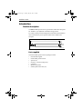
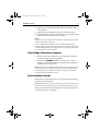
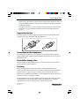
Distributed by
Any reference to Raytheon or
RTN in this manual should be
interpreted as Raymarine.
The names Raytheon and RTN
are owned by the
Raytheon Company.
81006_3.book Page 1 Tuesday, May 22, 2001 1:03 PM
Linear Rudder
Position Sensor
Installation Guide
Document number: 81006-3
Date: May 2001
81006_3.book Page 2 Tuesday, May 22, 2001 1:03 PM
2
Linear Rudder Position Sensor
Important information
Safety notices
WARNING:
Product installation
This equipment must be installed and operated in accordance
with the instructions contained in this handbook. Failure to do so
could result in poor product performance, personal injury
and/or damage to your boat.
Because correct performance of the boat’s steering is critical for
safety, we STRONGLY RECOMMEND that an Authorized
Raymarine Service Representative fits this product.
WARNING:
Navigation aid
Although we have designed this product to be accurate and
reliable, many factors can affect its performance. As a result, it
should only be used as an aid to navigation and should never
replace commonsense and navigational judgement. Always
maintain a permanent watch so you can respond to situations as
they develop.
EMC conformance
All Raymarine equipment and accessories are designed to the best
industry standards for use in the recreational marine environment.
The design and manufacture of Raymarine equipment and
accessories conform to the appropriate Electromagnetic
Compatibility (EMC) standards, but correct installation is required to
ensure that performance is not compromised.
Handbook information
To the best of our knowledge, the information in this handbook was
correct when it went to press. However, Raymarine cannot accept
liability for any inaccuracies or omissions it may contain. In addition,
our policy of continuous product improvement may change
specifications without notice. As a result, Raymarine cannot accept
liability for any differences between the product and the handbook.
© Raymarine Ltd 2001.
81006_3.book Page 3 Tuesday, May 22, 2001 1:03 PM
Installation Guide
3
Introduction
Product description
The linear rudder position sensor (part number: M81188) is designed
for ‘bullhorn’ style hydraulic outboard steering systems.
It is totally weatherproof and designed to be mounted on the bullhorn
ram. It transmits the precise position of the boat’s rudder to the
autopilot.
425 mm (16.75 in)
32 mm
(1.3 in)
D5389-1
Linear rudder position sensor - dimensions
Parts supplied
The linear rudder position sensor package contains:
•
•
•
•
•
•
•
this installation guide
linear rudder position sensor
spacers (x2)
80 mm (3.1 in) hose clamps (x2)
U-bracket
M8 nut and washer
female spade connectors (x4)
81006_3.book Page 4 Tuesday, May 22, 2001 1:03 PM
4
Linear Rudder Position Sensor
Mounting
Starboard
bolt
Nut and
washer
End
bracket
Bullhorn
ram shaft
Threaded
rod
U-bracket
Sensor
shaft
Sensor
shaft
Sensor
barrel
Alignment mark
Sensor
barrel
Cable
Hose clamp
Spacer
Bullhorn
ram
D5390-1
1. Use the steering system to position the bullhorn ram amidships.
2. If necessary, release the hydraulic pressure from the boat’s
hydraulic steering system
Note: Contact your steering gear manufacture for advice on this step,
and follow their instructions for releasing the hydraulic pressure.
3. Loosen the starboard bolt that secures the bullhorn ram’s shaft to
the end bracket.
4. Fit the U-bracket (supplied) over the end bracket and the bullhorn
ram’s shaft.
5. Hand tighten the starboard bolt to hold the U-bracket in place.
6. Fully open the hose clamps (supplied) using a flat bladed
screwdriver, then hang them over the bullhorn ram.
7. Place the spacers (supplied) on the bullhorn ram and use adhesive
tape to secure them temporarily.
8. Pull out the rudder sensor’s shaft until its alignment mark is level
with the end of the barrel.
9. Position the rudder sensor against the spacers so the threaded rod
end of its shaft passes through the U-bracket.
81006_3.book Page 5 Tuesday, May 22, 2001 1:03 PM
Installation Guide
5
10. Tighten the hose clamps around the bullhorn ram and the rudder
sensor’s barrel.
11. Tighten the starboard bullhorn bolt to secure the U-bracket.
12. Fit and tighten the supplied nut and washer to secure the threaded
rod end of the sensor’s shaft to the U-bracket.
Notes:
1. If there is restricted space below the ram, you can mount the sensor
in front of the ram (not below it).
2. We recommend installing the sensor with its shaft pointing to
starboard. If you cannot install the unit in this orientation, you can fit
it with the shaft pointing to port. If you do this, swap the red and green
connections at the course computer.
Connecting to the course computer
1. Route the cable to the autopilot or course computer, taking into
account the EMC installation guidelines.
2. Connect to the RUDDER terminals on the autopilot or course
computer, as described in the owner’s handbook. If required, fit
the spade connectors provided.
Note: To allow for the bullhorn’s movement, leave a loop of cable at
the end of the linear rudder position sensor. If the standard cable is
not long enough, your Raymarine dealer can supply a 10 m (30 ft)
extension cable (part number: D173).
Post installation checks
When you have connected the sensor to your autopilot, pressurize the
steering system (if required).
Note: Contact your steering gear manufacture for advice on this step.
Follow their instructions for re-pressurizing the hydraulic pressure.
When you have done this, check the sensor’s operation as described
in the autopilot owner’s handbook.
81006_3.book Page 6 Tuesday, May 22, 2001 1:03 PM
6
Linear Rudder Position Sensor
Raymarine EMC Guidelines
EMC Installation & Service Guidelines
IMPORTANT NOTE
All Raymarine equipment and accessories are designed to the best industry standards for
use in the leisure marine environment.
When powered up, all electrical equipment produces electromagnetic fields. These can
cause adjacent pieces of electrical equipment to interact with one another, with a
consequent adverse effect on operation. In order to minimise these effects and enable you
to get the best possible performance from your Raymarine equipment, these guidelines are
provided to enable you to ensure minimum interaction between different items of
equipment, i.e. ensure optimum Electromagnetic Compatibility (EMC).
The design and manufacture of Raymarine equipment and accessories conform to the
appropriate EMC standards, but correct installation is required to ensure that performance
is not compromised. Although every effort has been taken to ensure that they will perform
under all conditions, it is important to understand what factors could affect the operation of
the product. Please keep this document for future reference.
Safety
Some products generate high voltages, so never handle the cables/connectors when power
is being supplied to the equipment.
Installation
These guidelines describe the conditions for optimum EMC performance, but it is
recognised that it may not be possible to meet all of these conditions in all situations. To
ensure the best possible conditions for EMC performance within the constraints imposed
by any location, always ensure the maximum separation possible between different items
of electrical equipment.
For optimum EMC performance, it is recommended that wherever possible:
• Raymarine equipment and cables connected to it are:
• At least 1 m (3 ft) from any equipment transmitting or cables carrying radio signals
e.g. VHF radios, cables and antennas. In the case of SSB radios, the distance
should be increased to 2 m (7 ft).
• More than 2 m (7 ft) from the path of a radar beam. A radar beam can normally be
assumed to spread 20 degrees above and below the radiating element.
• The equipment is supplied from a separate battery from that used for engine start.
Voltage drops below 10 V in the power supply to our products, and starter motor
transients, can cause the equipment to reset. This will not damage the equipment, but
may cause the loss of some information and may change the operating mode.
Raymarine EMC Guidelines
•
•
Raymarine specified cables are used at all times. Cutting and rejoining these cables can
compromise EMC performance and so must be avoided unless doing so is detailed in
the installation manual.
If a suppression ferrite is attached to a cable, this ferrite should not be removed. If the
ferrite needs to be removed during installation it must be reassembled in the same
position.
Suppression Ferrites
The following illustration shows typical cable suppression ferrites fitted to Raymarine
equipment. Always use the ferrites supplied by Raymarine.
D3548-2
Connections to Other Equipment
If your Raymarine equipment is to be connected to other equipment using a cable not
supplied by Raymarine, a suppression ferrite MUST always be fitted to the cable close to
the Raymarine unit.
Check Before Going to Sea
Always check the installation before going to sea to make sure that it is not affected by
radio transmissions, engine starting etc.
Servicing
Raymarine equipment should be serviced only by authorised Raymarine service
technicians. They will ensure that service procedures and replacement parts used will not
affect performance. There are no user serviceable parts in any Raymarine product.
Always report any EMC related problem to your nearest Raymarine dealer. We use such
information to improve our quality standards.
In some installations it may not be possible to prevent equipment from being affected by
external influences. In general this will not damage the equipment but it can lead to
spurious resetting action, or momentarily may result in faulty operation.
Document number: 84018-5
Date: May 2001
81006_3.book Page 1 Tuesday, May 22, 2001 1:03 PM
Limited Warranty Certificate
Raymarine warrants each new Light Marine/Dealer Distributor Product to be of good materials and
workmanship, and will repair or exchange any parts proven to be defective in material and
workmanship under normal use for a period of 2 years/24 months from date of sale to end user, except
as provided below.
Defects will be corrected by Raymarine or an authorized Raymarine dealer. Raymarine will, except
as provided below, accept labor cost for a period of 2 years/24 months from the date of sale to end user.
During this period, except for certain products, travel costs (auto mileage and tolls) up to 100 round
trip highway miles (160 kilometres) and travel time of 2 hours, will be assumed by Raymarine only
on products where proof of installation or commission by authorized service agents, can be shown.
Warranty Limitations
Raymarine Warranty policy does not apply to equipment which has been subjected to accident, abuse
or misuse, shipping damage, alterations, corrosion, incorrect and/or non-authorized service, or
equipment on which the serial number has been altered, mutilated or removed.
Except where Raymarine or its authorized dealer has performed the installation, it assumes no
responsibility for damage incurred during installation.
This Warranty does not cover routine system checkouts or alignment/calibration, unless required by
replacement of part(s) in the area being aligned.
A suitable proof of purchase, showing date, place, and serial number must be made available to
Raymarine or authorized service agent at the time of request for Warranty service.
Consumable items, (such as: Chart paper, lamps, fuses, batteries, styli, stylus/drive belts, radar mixer
crystals/diodes, snap-in impeller carriers, impellers, impeller bearings, and impeller shaft) are
specifically excluded from this Warranty.
Magnetrons, Cathode Ray Tubes (CRT), TFT Liquid Crystal Displays (LCD) and cold cathode
fluorescent lamps (CCFL), hailer horns and transducers are warranted for 1 year/12 months from date
of sale. These items must be returned to a Raymarine facility.
All costs associated with transducer replacement, other than the cost of the transducer itself, are
specifically excluded from this Warranty.
Overtime premium labor portion of services outside of normal working hours is not covered by this
Warranty.
Travel cost allowance on certain products with a suggested retail price below $2500.00 is not
authorized. When/or if repairs are necessary, these products must be forwarded to a Raymarine
facility or an authorized dealer at owner’s expense will be returned via surface carrier at no cost to the
owner.
Travel costs other than auto mileage, tolls and two (2) hours travel time, are specifically excluded on
all products. Travel costs which are excluded from the coverage of this Warranty include but are not
limited to: taxi, launch fees, aircraft rental, subsistence, customs, shipping and communication
charges etc. Travel costs, mileage and time, in excess to that allowed must have prior approval in
writing.
TO THE EXTENT CONSISTENT WITH STATE AND FEDERAL LAW:
(1) THIS WARRANTY IS STRICTLY LIMITED TO THE TERMS INDICATED HEREIN, AND
NO OTHER WARRANTIES OR REMEDIES SHALL BE BINDING ON RAYMARINE
INCLUDING WITHOUT LIMITATION ANY WARRANTIES OF MERCHANTABLE OR
FITNESS FOR A PARTICULAR PURPOSE.
(2) Raymarine shall not be liable for any incidental, consequential or special (including punitive or
multiple) damages.
All Raymarine products sold or provided hereunder are merely aids to navigation. It is the
responsibility of the user to exercise discretion and proper navigational skill independent of any
Raymarine equipment.
Document number: 84064-8
April 2001
81006_3.book Page 2 Tuesday, May 22, 2001 1:03 PM
Factory Service Centers
United States of America
UK, Europe, Middle East, Far East
Raymarine Inc
22 Cotton Road, Unit D
Nashua, NH 03063-4219, USA
Raymarine Ltd
Anchorage Park, Portsmouth
PO3 5TD, England
Telephone: +1 603 881 5200
Fax: +1 603 864 4756
www.raymarine.com
Telephone: +44 (0)23 9269 3611
Fax: +44 (0)23 9269 4642
www.raymarine.com
Sales & Order Services
Telephone: +1 800 539 5539 Ext. 2333 or
+1 603 881 5200 Ext. 2333
Customer Support
Telephone: +44 (0)23 9271 4713
Fax: +44 (0)23 9266 1228
Technical Support
Telephone: +1 800 539 5539 Ext. 2444 or
+1 603 881 5200 Ext. 2444
Email: [email protected]
Email: [email protected]
Product Repair Center
Telephone: +1 800 539 5539 Ext. 2118
Stick barcode label here
Purchased from
Purchase date
Dealer address
Installed by
Installation date
Commissioned by
Commissioning date
Owner’s name
Mailing address
This portion should be completed and retained by the owner.