1
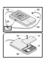
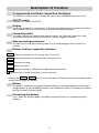
TorMinal
GB
Operating Instructions
20310V001-052006-0-OCE-Rev.G
Pages
1 - 28
A
A.2
A.3
A.4
A.1
A.5
ON
B
B.1
B.2
B.3
B.4
! Caution !
Valid as from control versions:
- duo 500 SL, sprint 550 SL, duo 650 SL: . . . . . . . . ver 015
- marathon 550 SL, 800 SL, 1100 SL: . . . . . . . . . . . ver 017
- twist 200: . . . . . . . . . . . . . . . . . . . . . . . . . . . . . . . . ver 030
- stargilder 300: . . . . . . . . . . . . . . . . . . . . . . . . . . . . ver 012
- marathon tiga 800 SL, - 1100 SL: . . . . . . . . . . . . . ver 010
- starglider 300 E: . . . . . . . . . . . . . . . . . . . . . . . . . . . ver 010
- gator 400: . . . . . . . . . . . . . . . . . . . . . . . . . . . . . . . . ver 010
- jive 200: . . . . . . . . . . . . . . . . . . . . . . . . . . . . . . . . . ver 030
Earlier control versions are not included here.
Contents
Table of Contents ............................................................2
Symbols
Safety Instructions
Normal Use
Supplied Components
Technical Data
Display of control version
2
2
3
3
3
4
Description of Function ..................................................6
Switching on the TorMinal
Connecting TorMinal to a control unit
7
7
Operation of Gate ............................................................7
Explanation of Terms ......................................................9
Memory Positions ..........................................................11
sprint 550 SL, duo 500 SL + 650 SL
marathon 550 SL, 800 SL, 1100 SL
twist 200 + DSTA24, jive 200 + DSTA24-UF
starglider 300, starglider 300 E, gator 400
marathon tiga 800 SL + 1100 SL
11
14
18
20
24
Miscellaneous ................................................................27
Troubleshooting
Maintenance
Disposal
Warranty and After-Sale Service
Explanations/Glossary
27
27
27
28
28
1
General information
Symbols
Symbol indicating potential danger! Failure to follow instructions may result in serious
injury to persons or damage to the drive mechanism!
Information, useful tip.
A.1
(1)
Refers in the introduction or in the body of the text to the corresponding
illustration.
General Safety Instructions
•
These Operating Instructions (BA) must be read, understood and observed by the person using the
TorMinal.
•
The manufacturer is not liable for any damage or malfunction caused by failure to observe these
Operating Instructions.
•
Always disconnect the drive mechanism from the mains supply and ensure it cannot be reconnected
before working on either the gate/door or drive mechanism.
•
•
•
Only use the TorMinal for the purpose described.
•
After changing the settings on a given control unit, the drive mechanism's automatic power cut-off
should be checked to ensure its compliance with the relevant standards applying at the time.
•
•
Always switch off the TorMinal after use.
Never use a TorMinal that is known to be damaged.
Read through these Operating Instructions before using the TorMinal and pay particular attention to
the Safety Instructions. Carry out the instructions as described in the order indicated and familiarise
yourself with the TorMinal's operation.
Do not carry the TorMinal by its power cable.
2
General information
Correct use
•
•
Any malfunction constituting a safety risk is to be eliminated without delay.
The TorMinal may only be connected to the following drive mechanisms operated
via SOMMER
- sprint 550 SL
- duo 500 SL, duo 650 SL
- marathon 550 SL, 800 SL, 1100 SL
- twist 200 + DSTA24
- starglider 300
- marathon tiga 800 SL, 1100 SL
- starglider 300 E
- gator 400
- jive 200 + DSTA24-UF
•
•
•
•
SOMMER accepts no liability for changes made to the settings of any given control unit.
The warranty lapses if any changes are made to the TorMinal's hardware or software.
SOMMER further accepts no liability for any changes made to a control unit via a TorMinal.
Do not store or operate the TorMinal in locations subject to wetness, steam, high humidity, dust,
sunlight or similar.
Any other or non-compliant use of the TorMinal is not deemed to be correct. SOMMER Antriebs- und
Funktechnik GmbH is not liable for any damage incurred as a result of such use; the operator/user
bears full responsibility for this. The warranty also lapses in such cases.
Scope of Supply
1 TorMinal incl. 9V block battery and connecting cable
1 set of Operating Instructions
1 Etui
Technical Data
Dimensions :
120 x 65 x 22 mm
Weight :
approx. 140 g (incl. battery and connecting cable)
Battery :
9V block
3
General information
Display of control version
Note!
The correct display of the control version of the drive system depends on the TorMinal
software version. If an incorrect control version is displayed (e.g. Test PCB), you can nevertheless make the necessary modifications.
To update the TorMinal software, return the TorMinal to SOMMER free of charge.
TorMinal with software version 1.00
Drive
Top display
Bottom display
sprint/duo SL
Sprint
e.g.: V0xx.000
marathon SL
Marathon
e.g.: V0xx.000
twist 200
DSTA24
e.g.: V0xx.000
starglider 300
Test-PCB
e.g.: V0xx.000
marathon tiga SL
Test-PCB
e.g.: V0xx.000
starglider 300 E
Test-PCB
e.g.: V0xx.000
gator 400
Test-PCB
e.g.: V0xx.000
jive 200
DSTA24
e.g.: V0xx.000
TorMinal with Softwareversion 1.10 and higher
Drive
Top display
sprint/duo SL
Sprint
Bottom display
e.g.: V0xx.000
marathon SL
Marathon
e.g.: V0xx.000
twist 200
DSTA24
e.g.: V0xx.000
starglider 300
STA24
e.g.: V0xx.000
marathon tiga SL
Test-PCB
e.g.: V0xx.000
starglider 300 E
Test-PCB
e.g.: V0xx.000
gator 400
Test-PCB
e.g.: V0xx.000
jive 200
DSTA24
e.g.: V0xx.000
TorMinal with Softwareversion 1.20 and higher
Drive
Top display
sprint/duo SL
sprint
Bottom display
e.g.: V0xx.000
marathon SL
marathon
e.g.: V0xx.000
twist 200
DSTA24
e.g.: V0xx.000
starglider 300
STA24
e.g.: V0xx.000
marathon tiga SL
tiga
e.g.: V0xx.000
starglider 300 E
Test-PCB
e.g.: V0xx.000
gator 400
Test-PCB
e.g.: V0xx.000
jive 200
DSTA24
e.g.: V0xx.000
4
General information
TorMinal with software version 1.30 and higher
Drive
Top display
sprint/duo SL
sprint
Bottom display
e.g.: V0xx.000
marathon SL
marathon
e.g.: V0xx.000
twist 200
DSTA24
e.g.: V0xx.000
starglider 300
STA24
e.g.: V0xx.000
marathon tiga SL
tiga
e.g.: V0xx.000
starglider 300 E
STA1
e.g.: V0xx.000
gator 400
STA1
e.g.: V0xx.000
jive 200
DSTA24
e.g.: V0xx.000
5
Description of Function
A+B
Components and their respective functions
The TorMinal is used to check or change the values set on SOMMER drive control units.
A.1 ON/OFF switch
Switches the TorMinal ON or OFF.
A.2 Display
The display comprises 2 x 8 characters. The upper line displays the given memory slot (Mem)
and its number whilst the lower line shows the corresponding setting (Val).
A.3 Connecting cablel
This cable connects the TorMinal with the given control unit. The plug is fitted with a safe
connecting mechanism (PIN) to ensure that it is always plugged in correctly.
A.4 Safe connecting mechanism
This PIN ensures that the connecting cable (A.3) is always plugged into the control unit
correctly.
A.5 Buttons and their respective functions
Mem + selects the next memory slot up (e.g. from 014 to 015).
Mem - selects the next memory slot down (e.g. from 014 to 013).
Val + increases the value.
Val -
reduces the value.
Esc
reverses a change in setting that has not yet been memorised.
memorises the value set or confirms a control unit reset.
• Pressing the Esc + Mem + buttons at the same time reinstates the control unit's default values
and all value changes are deleted.
B.3 Battery
The power is supplied by a standard 9V block battery that can be obtained from retail outlets
selling batteries or from SOMMER Antriebs- und Funktechnik GmbH. The battery must always
be fitted as shown in illustration (B).
B.4 Connecting the battery
This is where the 9V block battery should be connected. Ensure it is connected correctly
(polarity)!
6
Operation
Safety instructions !
Important to note !
Before any change to the settings, reset the control system (deletion of force values, for
details see installation and operating manual of your operator). Reset with the TorMinal is
not sufficient, as the force values are not deleted and only the parameters that can be
adjusted with the TorMinal are reset to the factory values.
The control unit has to relearn the running times and required forces.
Prior to any work at the gate or operator, disconnect the operator system from the power supply and
secure it against inadvertent reconnection or actuation.
Do not touch the strip conductors on the control board.
Switching on the TorMinal
A
• Push switch (A.1) into ON position.
- The message "TorMinal Vx.x" appears on the display showing which version of the TorMinal
is being used.
- If a button is pressed when the TorMinal is not connected to any control unit, the message
"!No PCB!" appears
- If it is connected to a control unit, the control unit type, software version and control unit
version are displayed, e.g. as follows:
.
marathon
V017.000
Connecting TorMinal to a control unit
A
• Take control unit out of
drive mechanism - see Installation and Operating Instructions for
drive mechanism.
• Connect cable (A.3) to control unit, ensuring correct connection (polarity).
- the connecting cable's red lead should always point towards the control unit's coding hole.
Reading and displaying settings
•
The next time a button is pressed on control panel [A.5], the settings are read and displayed:
The upper line displays the memory slot (Mem).
The lower line displays the value set (Val) :
- "x" preceding setting (Val) means the value cannot be changed.
- "s" preceding setting (Val) means the value can be changed and memorised.
7
Operation
Changing and memorising settings
When the setting has been changed, the preceding "s" disappears. This indicates that the setting has
been changed but not yet memorised.
Procedure :
1. Select required memory slot (Mem) by pressing buttons Mem + or Mem - , see "Memory Slots and
their Respective Functions" section.
2. Change setting by pressing buttons Val + or
Val - .
3. When the required value has been set, this is memorised by pressing button
once.
By way of confirmation, an "s" appears preceding the set and now memorised value.
Reverting values to default settings – Reset
Important to note !
Only the values reset with TorMinal to the factory settings are changed, and no force values are deleted.
1. Press buttons Mem + and Esc at the same time
- message "Reset to default?" appears
2. Confirm this message by pressing this button
Message "ALL RESET !"
, all values thus revert to default settings
Important to note !
If no reset is required, the procedure can be interrupted by pressing the
Esc
3. Press any button and the message disappears.
All the values have now reverted to default settings.
Changing the battery
A
• Switch TorMinal off.
• Remove screw (B.1), open battery compartment (B.2).
• Take battery (B.3) out and disconnect.
• Replace old battery (B.3) with one of the same type.
Ensure battery cable does not get trapped. Ensure correct (+/-) connection !
• Fit battery (B.3), close battery compartment (B.2). Fit screw (B.1) and tighten up.
8
button.
Explanation of Terms Used
The TorMinal can be used to set SOMMER's new drive mechanisms to suit almost all types of
gate/door. The illustration here shows the drive unit's speed curve (default setting without 2) when
opening or closing a gate/door.
2
8
1
7
5
6
4
2
1. Maximum speed
The drive mechanism's top speed - separately adjustable for opening and closing.
2. Soft run mode
Can be additionally selected and separately adjusted:
- when the drive mechanism leaves its end CLOSE + OPEN positions.
- when the drive mechanism moves into its end CLOSE + OPEN positions
3. Gate/door end OPEN position
Gate/door is open
4. Soft run speed
The drive mechanism's lowest speed - separately adjustable for opening and closing.
Important to note !
The soft run speed must be at least 2 settings lower than the maximum speed.
5. Soft run ramp
The time the drive mechanism needs to reach its maximum or soft run speed.
6. Gate/door end CLOSE position
Gate/door is closed
9
3
Explanation of Terms Used
7. Zero line
8. Max. line
The maximum speed that can be set. The speed setting range lies between the zero line and the
max. line.
Travel time
The time the drive mechanism needs to close or open a gate/door.
Cycle counter
Cycle = movement, comprising one complete opening and closing movement between the end travel
positions. Only when the gate/door reaches the gate/door end CLOSE position is a cycle counted.
Backjump
Serves to reduce strain on the gate/door and drive mechanism workings. When the gate/door has
reached its end CLOSE position, it moves back a short distance in the direction of gate/door OPEN to
thus relieve the gate/door and drive workings.
10
Memory Slots and their Respective Functions
This is where the settings of the individual memory slots can be read.
The first column displays the memory slot concerned, the second the available setting range (the first
number is the lowest and the second number the highest possible setting), the third column describes
the given slot's function and the fourth column the given slot's default setting.
sprint 550 SL, duo 500 SL + 650 SL
Memory slot
Mem
Setting
range
Val
Description of respective
functions
Default setting = Val
sprint / duo SL
003
Force taught for gate/door opening (OPEN)
004
- 1)
- 1)
Force taught for gate/door closing (CLOSE)
255 3)
255 3)
005
- 1)
Gate/door open travel time (OPEN)
255 3)
- 1)
Gate/door close travel time (CLOSE)
- 2)
Cycle counter (Z1)
- 2)
Cycle counter (Z2): counts from 0 to 255
006
011
012
013
0 - 255
Value in steps of 0.25 seconds
Example: value shown is 40 = 10 seconds
Value in steps of 0.25 seconds
Example: value shown is 40 = 10 seconds
Number of cycles: counter status times 256
Number of cycles in total: Z1 x 256 + Z2
Example: 3 x 256 + 77 = 845
Partial opening time
Size of partial opening, adjustable in steps of
0.25 seconds.
017
0 - 255
Length of soft run from gate/door end OPEN
position or gate/door end CLOSE position
255 3)
255 3)
255 3)
255 3)
0
Up until acceleration to maximum speed
0 - no soft run, 255 - max. length
Length soft run
Gate/door end
OPEN position
018
0-8
Gate/door end
CLOSE position
Length of soft run ramp
4
High value = long ramp, low value = short ramp
1) Value displayed cannot be changed, and is read and memorised by the control unit when the force
values and travel times are taught.
2) Value displayed cannot be changed.
3) When supplied, the value 255 has been set. Once the force values and travel time have been
taught, the values that are actually needed are then memorised.
4) Perform reset, otherwise these values cannot be changed.
11
Memory Slots and their Respective Functions
Memory slot
Mem
Setting
range
Val
019
15 - 60
Description of respective
functions
Soft run speed when opening
Default setting = Val
sprint / duo SL
25
020
15 - 60
Maximum speed when opening
55 4)
Note!
Memory position (020) can only be modified after the control system has been reset
(force values deleted). Such a system reset cannot be completed with the TorMinal software.
021
0 - 40
Start of soft run ramp for gate/door end OPEN position
15
Start of soft run ramp prior to drive mechanism moving into
gate/door end OPEN position. Adjustable in steps of
0.25 seconds.
Start of soft run ramp
Start from gate/
door end CLOSE position
Stop in gate/
door end OPEN position
022
15 - 60
Soft run speed when closing
023
15 - 60
Maximum speed when closing
25
45 4)
Note!
Memory position (023) can only be modified after the control system has been reset
(force values deleted). Such a system reset cannot be completed with the TorMinal software.
024
4 - 40
Start of soft run ramp for gate/door end CLOSE position
15
Start of soft run ramp prior to drive mechanism moving into
gate/door end CLOSE position. Adjustable in steps of
0.25 seconds.
Start of soft run ramp
Start from gate/
door end OPEN position
028
4 - 40
Stop in gate/
door end CLOSE position
Early warning period
12
Duration of early warning period, adjustable in steps of
0.25 seconds. 4 = 1 Second, 40 = 10 seconds
030
-
031
1 - 255
No function
5
Duration of light ON period after opening of gate/door
175
Adjustable in steps of 1 second.
032
1 - 255
Duration of light ON period after closing of gate/door
175
Adjustable in steps of 1 second.
033
0 - 255
Back jump
20
Adjustable in steps of 1 millisecond.
034
4 - 255
Reversing period
8
Duration of reversing period when safety input has been
tripped or when automatic power cut-off occurs. Adjustable
in steps of 0.25 seconds.
12
Memory Slots and their Respective Functions
Memory slot
Mem
Setting
range
Val
035
0 - 15
Description of respective
functions
Switching soft run ramps ON or OFF
Default setting = Val
sprint / duo SL
15
This function enables the soft run ramps to be switched ON
or OFF individually.
All soft run ramps (1 - 4) activated
= 15
Ramp 1 (start from gate/door end CLOSE position) ON = 1
Ramp 2 (stop in gate/door end OPEN position) ON
= 2
Ramp 3 (start from gate/door end OPEN position) ON = 4
Ramp 4 (stop in gate/door end CLOSE position) ON
= 8
Setting and memorising required values
Example 1:
Switch off ramp 1 + ramp 2: 15 - 1 -2 = 12, input and
memorise this value (12).
Example 2:
Switch on ramp 2 + ramp 4:
2 + 8 = 10, input and memorise this value (10).
036
-
037
16 - 48
No function
0
Force tolerance
Adjustable additional force tolerance
16 = min. additional force, 48 = max. additional force
48 4)
Note!
Memory position (037) can only be modified after the control system has been reset
(force values deleted). Such a system reset cannot be completed with the TorMinal software.
047
-
For factory testing purposes
13
-
Memory Slots and their Respective Functions
marathon 550 SL, 800 SL, 1100 SL
Memory slot
Mem
Setting
range
Val
003
Force taught when opening gate/door (OPEN)
004
- 1)
- 1)
Force taught when closing gate/door (CLOSE)
255 3)
255 3)
005
- 1)
Travel time when opening gate/door (OPEN)
255 3)
- 1)
Travel time when closing gate/door (CLOSE)
- 2)
Cycle counter (Z1)
- 2)
Cycle counter (Z2): counts from 0 to 255
006
011
012
013
0 - 255
Description of respective
functions
Value in steps of 0.25 seconds
Example: value shown 40 = 10 seconds
Value in steps of 0.25 seconds
Example: value shown 40 = 10 seconds
Number of cycles: counter status times 256
Number of cycles in total: Z1 x 256 + Z2
Example: 3 x 256 + 77 = 845
Partial opening time
Size of partial opening, adjustable in steps of 0.25 seconds.
017
0 - 255
Length of soft run from gate/door end OPEN
position or gate/door end CLOSE position
Default setting = Val
marathon SL
255 3)
255 3)
255 3)
255 3)
0
Up until acceleration to maximum speed
0 - no soft run, 255 - max. length
Length soft run
Gate/door end
OPEN position
018
0-8
Gate/door end
CLOSE position
Length of soft run ramp
4
High value = long ramp, low value = short ramp
019
15 - 60
Soft run speed when opening
020
15 - 60
Maximum speed when opening
25
55 4)
Note!
Memory position (020) can only be modified after the control system has been reset
(force values deleted). Such a system reset cannot be completed with the TorMinal software.
1) Value displayed cannot be changed, and is read and memorised by the control unit when the force
values and travel times are taught.
2) Value displayed cannot be changed.
3) When supplied, the value 255 has been set. Once the force values and travel time have been
taught, the values that are actually needed are then memorised.
4) Perform reset, otherwise these values cannot be changed.
14
Memory Slots and their Respective Functions
Memory slot
Mem
Setting
range
Val
Description of respective
functions
Default setting = Val
marathon SL
021
0 - 40
Start of soft run ramp for gate/door end OPEN position
15
Start of soft run ramp prior to drive mechanism moving into
gate/door end OPEN position. Adjustable in steps of
0.25 seconds.
Start of soft run ramp
Start from gate/
door end OPEN position
Stop in gate/door
end CLOSE position
022
15 - 60
Soft run speed when closing
023
15 - 60
Maximum speed when closing
25
45 4)
Note!
Memory position (023) can only be modified after the control system has been reset
(force values deleted). Such a system reset cannot be completed with the TorMinal software.
024
4 - 40
Start of soft run ramp for gate/door end CLOSE position
15
Start of soft run ramp prior to drive mechanism moving into
gate/door end CLOSE position. Adjustable in steps of
0.25 seconds.
Start of soft run ramp
Start from gate/
door end CLOSE position
026
0 - 255
Stop in gate/
door end OPEN position
Cycle counter for maintenance
0
Indication of a set value which when reached should
activate the maintenance signal.
Example: input of a set value of 2 means that after
512 cycles the equipment should be serviced. If the next
service is required after a further 512 cycles, then a value
of 4 has to be input during the given maintenance session.
028
4 - 40
Early warning period
12
Duration of early warning period, adjustable in steps of
0.25 seconds. 4 = 1 second, 40 = 10 seconds
030
1 - 20
Closing period - light barrier
5
Period during which gate/door is kept open after the light
barrier has been crossed - only possible in conjunction with
automatic closing mechanism. Adjustable in steps of 1 sec.
031
1 - 255
Duration of light ON period after opening of gate/door
175
Adjustable in steps of 1 second.
032
1 - 255
Duration of light ON period after closing of gate/door
175
Adjustable in steps of 1 second.
033
0 - 255
Back jump
20
Adjustable in steps of 1 millisecond.
034
4 - 255
Reversing period
8
Duration of reversing period when safety input has been
tripped or when automatic power cut-off occurs.
Adjustable in steps of 0.25 seconds.
15
Memory Slots and their Respective Functions
Memory slot
Mem
Setting
range
Val
035
0 - 255
Description of respective
functions
1. Switching soft run ramps ON or OFF
Default setting = Val
marathon SL
31
This function enables the soft run ramps to be switched ON
or OFF individually.
All soft run ramps (1 - 4) activated
= 15
Ramp 1 (start from gate/door end CLOSE position) ON = 1
Ramp 2 (stop in gate/door end OPEN position) ON
=2
Ramp 3 (start from gate/door end OPEN position) ON = 4
Ramp 4 (stop in gate/door end CLOSE position) ON
=8
Setting and memorising required values
Example 1:
Switch off ramp 1 + ramp 2:
15 - 1 -2 = 12, input and memorise this value (12).
Example 2:
Switch on ramp 2 + ramp 4:
2 + 8 = 10, input and memorise this value (10).
2. Functionality of relay output
(terminal 23 + 24)
- relay OFF
=
0
- pulse generated when motor starts =
16
- status indicator, contact OPEN when gate/door OPEN = 32
- status indicator, contact CLOSED
when gate/door OPEN
=
48
3. Maintenance monitoring
Before the maintenance monitoring mode can be activated,
the number of cycles requiring monitoring needs to be set
on memory slot 026.
- monitoring function OFF
= 0
- monitoring maintenance cycles
= 64
- maintenance alarm has been activated
= 128
When the maintenance alarm has been activated, the value
set on memory slot 035 is increased by 128.
Deleting maintenance alarm:
reduce value set on memory slot 035 by 128.
Memory slot 035 has several functions (see 1 - 3); all the values need to be added together and input
in order to reach the required setting.
Factory settings:
1. All soft run ramps ON
value
15
2. Pulse at motor start ON
value
16
value
0
3. Maintenance monitoring OFF
total value 31
Example 1:
1. All soft run ramps ON
2. Relay output OFF
3. Maintenance monitoring ON
value
value
value
gives a total of
15
0
64
79
Input and memorise this value (79) on memory slot 035 to make all the required settings.
16
Memory Slots and their Respective Functions
Memory slot
Mem
Setting
range
Val
036
0 - 31
Description of respective
functions
Default setting = Val
marathon SL
Special functions 2
0 4)
Note!
Memory position (036) can only be modified after the control system has been reset
(force values deleted). Such a system reset cannot be completed with the TorMinal software.
1. Dead man mode only via button 1 + 2
By pressing button 1, the gate opens; by pressing button 2,
the gate closes.
- OFF
=0
- when closing
=1
(opening also possible via radio)
- when opening and closing
=3
2. Fraba system
- activate Fraba system evaluation
DIL switch 2 without function
= 16
Memory slot 036 has various functions (see 1, 2); to reach the desired setting, all the values have to
added together and entered.
Example:
1. Dead man operating mode when closing
value
1
2. Activate Fraba system
value
16
equals
17
Enter this value (17) for memory slot 036 and save; all the desired settings have thus been made.
037
16 - 48
Force tolerance
Adjustable additional force tolerance
16 = min. additional force, 48 = max. additional force
48 4)
Note!
Memory position (037) can only be modified after the control system has been reset
(force values deleted). Such a system reset cannot be completed with the TorMinal software.
047
-
For factory testing purposes
17
-
Memory Slots and their Respective Functions
twist 200 + DSTA24, jive 200 + DSTA24-UF
Memory slot
Mem
Setting
range
Val
002
- 2)
Cycle counter (Z1)
- 2)
Cycle counter (Z2): counts from 0 to 255
- 1)
- 1)
Travel time for gate/door wing 2 to open
Travel time for gate/door wing 1 to open
008
- 1)
- 1)
013
- 1)
Force taught when opening gate/door wing 2
014
- 1)
- 1)
Force taught when closing gate/door wing 2
- 1)
0 - 40
Force taught when closing gate/door wing 1
003
005
006
007
015
016
021
Description of respective
functions
Number of cycles: counter status times 256
Number of cycles in total: Z1 x 256 + Z2
Example: 3 x 256 + 77 = 845
Travel time for gate/door wing 2 to close
Travel time for gate/door wing 1 to close
Force taught when opening gate/door wing 1
Start of soft run ramp for gate/door end
OPEN and CLOSE positions
Default setting = Val
twist 200 + DSTA24
jive 200 + DSTA24-UF
255 3)
255 3)
255 3)
255 3)
255 3)
255 3)
255 3)
255 3)
255 3)
255 3)
14
Start of soft run ramp prior to drive mechanism moving into
gate/door end OPEN or CLOSE position. Adjustable in
steps of 0.25 seconds.
Start of soft run ramp
Stop in gate/door
end OPEN or
CLOSE position
Start from gate/
door end OPEN
or CLOSE position
019
15 - 60
Soft run speed when closing
020
15 - 60
Maximum speed when closing
023
4 - 16
-
024
2 - 255
Period during which gate/door is kept open - only possible in conjunction with automatic closing mechanism.
25
55 4)
8
60
Period during which gate/door is kept open; adjustable in steps
of 1 second.
026
0 - 40
Early warning period
12
Duration of early warning period, adjustable in steps of
0.25 seconds. 4 = 1 second, 40 = 10 seconds
027
4 - 40
Duration of delay in opening gate/door wing 1
10
The period after which gate/door wing 1 opens after
gate/door wing 2 has already been opened. Adjustable in
steps of 0.25 seconds.
1) Value displayed cannot be changed, and is read and memorised by the control unit when the force values and travel times are taught.
2) Value displayed cannot be changed.
3) When supplied, the value 255 has been set. Once the force values and travel time have been taught, the values that are actually
needed are then memorised.
4) Perform reset, otherwise these values cannot be changed.
18
Memory Slots and their Respective Functions
Memory slot
Mem
Setting
range
Val
Description of respective
functions
Default setting = Val
twist 200 + DSTA24
jive 200 + DSTA24-UF
028
8 - 40
Duration of delay in closing gate/door wing 2
20
The period after which gate/door wing 2 reaches gate/door
end CLOSE position after gate/door wing 1 has already
reached this position Adjustable in steps of 0.25 seconds.
030
1 - 20
Closing period - light barrier
5
Period during which gate/door is kept open after the light
barrier has been crossed - only possible in conjunction with
automatic closing mechanism.
Adjustable in steps of 1 second.
031
1 - 255
Switching period of relay contact
3
Period during which the relay contact is closed after the
motor has started. Adjustable in steps of 1 second.
047
-
For factory testing purposes.
19
-
Memory Slots and their Respective Functions
starglider 300, starglider 300 E, gator 400
Memory slot
Mem
Setting
range
Val
Description of respective
functions
Default settings = Val
starglider 300 + 300 E,
gator 400
003
Programmed force for gate opening (OPEN)
004
- 1)
- 1)
Programmed force for gate closing (CLOSED)
255 3)
255 3)
005
- 1)
Runtime of gate opening (OPEN)
255 3)
- 1)
Runtime of gate closing (CLOSED)
- 2)
Cycle counter (Z1)
- 2)
Cycle counter (Z2) counts from 0 to 255
006
011
012
013
0 - 255
Value in steps of 0.25 seconds Example: displayed
value 40 = 10 seconds
Value in steps of 0.25 seconds Example: displayed
value 40 = 10 seconds
255 3)
Number of cycles: counter value x 256
Total number of cycles: Z1 x 256 + Z2
Example: 3 x 256 + 77 = 845
Partial opening time
Extent of partial opening, adjustable in steps of
0.25 seconds
017
0 - 255
255 3)
Duration of soft run from end position gate
OPEN or gate CLOSED
255 3)
255 3)
0
Time up to acceleration to max. speed 0 - no soft run,
255 - max. duration
Duration of soft run
Stop at position
gate OPEN
018
0-8
Stop at position
gate CLOSED
Length of soft run ramp
4
high value = long ramp, low value = short ramp
019
15 - 60
Soft run speed for opening
020
15 - 60
Maximum speed for opening
27
55 4)
Note!
Memory position (020) can only be modified after the control system has been reset
(force values deleted). Such a system reset cannot be completed with the TorMinal software.
1) Displayed value cannot be changed; established and saved by the control system during teach-in
procedures for forces and runtimes.
2) Displayed value cannot be changed.
3) The factory settings for this value are 255. After completion of the teach-in procedures for forces
and runtimes, the actually required value is stored.
4) To change the values, you must first reset the control system.
20
Memory Slots and their Respective Functions
Memory slot
Mem
Setting
range
Val
Description of respective
functions
Default settings = Val
starglider 300 + 300 E,
gator 400
021
0 - 40
Start of soft run ramp for end position gate OPEN
15
Start of the soft run ramp before drive moves gate to end
position OPEN. Adjustable in steps of 0.25 seconds.
Start of soft run ramp
Start from end
position gate CLOSED
Stop in end
position gate OPEN
022
15 - 60
Soft run speed for closing
023
15 - 60
Maximum speed for closing
27
45 4)
Note!
Memory position (023) can only be modified after the control system has been reset
(force values deleted). Such a system reset cannot be completed with the TorMinal software.
024
0 - 40
Start of soft run ramp for end position gate CLOSED
15
Start of the soft run ramp before drive moves gate to end
position CLOSED. Adjustable in steps of 0.25 seconds
Start of soft run ramp
Start from end
position gate OPEN
026
0 - 255
Stop in end
position gate CLOSED
Cycle counter for servicing
0
Enter a value; when this value is reached, a warning is
displayed.
Example: Entered value: 2: after 512 cycles, the gate is to
be serviced. If another service is to be competed after
another 512 cycles, enter value “4”.
028
4 - 40
Preliminary warning time
12
Duration of preliminary warning time, adjustable in steps of
0.25 seconds. 4 = 1 second, 40 = 10 seconds
030
1 - 20
Closing time with light barrier
5
Duration of time during which the gate is kept open after the
light barrier is triggered; only in conjunction with automatic
closing. Adjustable in steps of 1 second.
031
1 - 255
Duration for light ON after opening of gate
175
Adjustable in steps of 1 second.
032
1 - 255
Duration for light ON after closing of gate
175
Adjustable in steps of 1 second.
034
4 - 255
Reversion time
2
Duration of reversion upon triggering of safety input or in
the event of force cut-off. Adjustable in steps of
0.25 seconds.
21
Memory Slots and their Respective Functions
Memory slot
Mem
Setting
range
Val
035
0 - 255
Description of respective
functions
1. Switching soft run ramps on/off
Default settings = Val
starglider 300 + 300 E,
gator 400
26
This function allows you to individually switch on or off soft
run ramps.
All soft run ramps (1 - 4) ON
= 15
Ramp 1 (start from end position
gate CLOSED) ON
= 1
Ramp 2 (stop in end position gate OPEN) ON
= 2
Ramp 3 (start from end position gate OPEN) ON = 4
Ramp 4 (stop in end position gate CLOSED) ON = 8
Enter and save the desired values.
Example 1:
Ramp 1 + ramp 2 OFF: 15 - 1 -2 = 12; enter and save
value 12.
Example 2:
Ramp 2 + ramp 4 ON: 2 + 8 = 10; enter and save value 10.
2. Functions of relay output
(terminals 23 + 24)
- Relay OFF
=
0
- Pulse at motor start
=
16
- Status display; contact open when gate open = 32
- Status display; contact closed when gate open = 48
3. Maintenance monitoring
If maintenance monitoring is enabled, enter the number of
cycles to be monitored at memory position 026.
- Monitoring OFF
=
0
- Monitoring of cycles ON
=
64
- Monitoring alarm triggered
=
128
If the monitoring alarm is triggered, the value at memory
position 035 is increased by 128. To delete memory alarm:
reduce value at memory position 035 by 128.
Memory position 035 is assigned several functions (see 1 - 3); in order to obtain the desired settings,
all values must be added and entered. Example 1:
Factory settings:
1. Soft run ramps 2 + 4 ON
value
10
2. Pulse at motor start ON
value
16
value
0
3. Maintenance monitoring OFF
total value 26
Example 1:
1. All soft run ramps ON
value
15
2. Relay output OFF
value
0
value
64
3. Maintenance monitoring ON
total value 79
To apply the above settings, value 079 must be entered and saved at memory position 035.
22
Memory Slots and their Respective Functions
Memory slot
Mem
Setting
range
Val
Description of respective
functions
Default settings = Val
starglider 300 + 300 E,
gator 400
036
0 - 31
Special functions 2
0 4)
Note!
Memory position (036) can only be modified after the control system has been reset (force
values deleted). Such a system reset cannot be completed with the TorMinal software.
1. Biased-off operation only with buttons 1 + 2
By pressing button 1, the gate opens; by pressing button 2,
the gate closes.
- OFF
=0
- For closing
=1
(opening also possible through radio channel 1)
- For opening and closing
=3
2. Fraba-System
- Fraba-System Auswertung einschalten
DIL-Schalter 2 ohne Funktion
037
16 - 255
= 16
Force tolerance
Adjustable additional force tolerance
16 = min. additional force, 255 = max. additional force
35 4)
Note!
Memory position (037) can only be modified after the control system has been reset
(force values deleted). Such a system reset cannot be completed with the TorMinal software.
047
-
For factory testing purposes
23
-
Memory Slots and their Respective Functions
marathon tiga 800 SL + 1100 SL
Memory slot
Mem
Setting
range
Val
Description of respective
functions
Default setting = Val
marathon tiga SL
003
Force taught when opening gate/door (OPEN)
004
- 1)
- 1)
Force taught when closing gate/door (CLOSE)
255 3)
255 3)
005
- 1)
Travel time when opening gate/door (OPEN)
255 3)
- 1)
Travel time when closing gate/door (CLOSE)
- 2)
Cycle counter (Z0)
- 2)
Cycle counter (Z1):
- 2)
Cycle counter (Z2) counts from 0 to 255
006
011
012
013
017
0 - 255
Value in steps of 0.25 seconds
Example: value shown 40 = 10 seconds
Value in steps of 0.25 seconds
Example: value shown 40 = 10 seconds
Number of cycles: counter status times 16.536
255 3)
255 3)
255 3)
Number of cycles in total:256
Total number of cycles:
Z0 × 16.536 + Z1 × 256 + Z2 = number of cycles
Length of soft run from gate/door end OPEN
position or gate/door end CLOSE position
255 3)
0
Up until acceleration to maximum speed
0 - no soft run, 255 - max. length
Length soft run
Gate/door end
OPEN position
018
0-8
Gate/door end
CLOSE position
Length of soft run ramp
4
High value = long ramp, low value = short ramp
019
15 - 60
Soft run speed when opening
020
15 - 60
Maximum speed when opening
25
55 4)
Note!
Memory position (020) can only be modified after the control system has been reset
(force values deleted). Such a system reset cannot be completed with the TorMinal software.
1) Value displayed cannot be changed, and is read and memorised by the control unit when the force
values and travel times are taught.
2) Value displayed cannot be changed.
3) When supplied, the value 255 has been set. Once the force values and travel time have been
taught, the values that are actually needed are then memorised.
4) Perform reset, otherwise these values cannot be changed.
24
Memory Slots and their Respective Functions
Memory slot
Mem
Setting
range
Val
Description of respective
functions
Default setting = Val
marathon tiga SL
021
0 - 40
Start of soft run ramp for gate/door end OPEN position
15
Start of soft run ramp prior to drive mechanism moving into
gate/door end OPEN position. Adjustable in steps of
0.25 seconds.
Start of soft run ramp
Start from gate/
door end OPEN position
Stop in gate/door
end CLOSE position
022
15 - 60
Soft run speed when closing
023
15 - 60
Start of soft run ramp for gate/door end
25
45 4)
Note!
Memory position (023) can only be modified after the control system has been reset
(force values deleted). Such a system reset cannot be completed with the TorMinal software.
024
0 - 40
Start of soft run ramp for gate/door end CLOSE position
15
Start of soft run ramp prior to drive mechanism moving into
gate/door end CLOSE position. Adjustable in steps of
0.25 seconds.
Start of soft run ramp
Start from gate/
door end CLOSE position
026
0 - 255
Stop in gate/door
end OPEN position
Cycle counter for maintenance
0
Indication of a set value which when reached should
activate the maintenance signal.
Example: input of a set value of 2 means that after
512 cycles the equipment should be serviced. If the next
service is required after a further 512 cycles, then a value
of 4 has to be input during the given maintenance session.
027
0 - 255
Warning time OPEN
16
Duration of early warning period, adjustable in steps of
0.25 seconds. 4 = 1 second, 40 = 10 seconds
028
0 - 255
Warning time CLOSE
20
Duration of early warning period, adjustable in steps of
0.25 seconds. 4 = 1 second, 40 = 10 seconds
030
1 - 20
Closing time with light barrier or extension of
gate open time
Depending on DIP switch positions 4 or 5, whereby DIP
switch 4 has precedence:
DIP 4 OFF: Standard gate open time
DIP 4 ON: Gate closes X seconds after the light
barrier has been triggered.
DIP 5 OFF: Standard gate open time
DIP 5 ON: After the light barrier has been triggered, the
gate open time is extended by X seconds
Adjustable in steps of 1 second.
25
5
Memory Slots and their Respective Functions
Memory slot
Mem
Setting
range
Val
031
2 - 255
Description of respective
functions
Gate open time
Default setting = Val
marathon tiga SL
30
Adjustable in steps of 1 second.
032
0 - 255
Clearing time
40
Adjustable in steps of 0.25 seconds
033
0 - 255
Back jump
20
Adjustable in steps of 1 millisecond.
034
4 - 255
Reversing period
8
Duration of reversing period when safety input has been
tripped or when automatic power cut-off occurs. Adjustable
in steps of 0.25 seconds.
035
0 - 255
1. Switching soft run ramps ON or OFF
15
This function enables the soft run ramps to be switched ON
or OFF individually.
All soft run ramps (1 - 4) activated
= 15
Ramp 1 (start from gate/door end CLOSE position) ON = 1
Ramp 2 (stop in gate/door end OPEN position) ON
=2
Ramp 3 (start from gate/door end OPEN position) ON = 4
Ramp 4 (stop in gate/door end CLOSE position) ON
=8
Setting and memorising required values
Example 1:
Switch off ramp 1 + ramp 2:
15 - 1 -2 = 12, input and memorise this value (12).
Example 2:
Switch on ramp 2 + ramp 4:
2 + 8 = 10, input and memorise this value (10).
2. Maintenance monitoring
Before the maintenance monitoring mode can be activated,
the number of cycles requiring monitoring needs to be set
on memory slot 026.
- monitoring function OFF
= 0
- monitoring maintenance cycles
= 64
- maintenance alarm has been activated
= 128
When the maintenance alarm has been activated, the value
set on memory slot 035 is increased by 128.
Deleting maintenance alarm: reduce value set on memory
slot 035 by 128.
037
16 - 60
Force tolerance
Adjustable additional force tolerance
16 = min. additional force, 48 = max. additional force
48 4)
Note!
Memory position (037) can only be modified after the control system has been reset
(force values deleted). Such a system reset cannot be completed with the TorMinal software.
047
-
For factory testing purposes
26
-
Miscellaneous
Troubleshooting
Fault/Behaviour
- Cause/Message on display
Display does not work
- TorMinal switched off
- Display defective - TorMinal dropped on floor
- Battery flat
- Display is black
Message on display
- ! No PCB !
Possible remedial action
-
Switch TorMinal on
Replace TorMinal
Replace battery
Connecting cable plugged in incorrectly
- No control unit connected
- Connecting cable (A.3) defective
Setting cannot be changed
- Preceded by an "x"
- Default setting cannot be changed
Reset value to default setting
- Preceded by an "s"
- Changed value has not been memorised
- RESET carried out; all values reverted to
default settings
Maintenance/Care
Wipe housing with damp cloth as required. Warm water with a little washing-up liquid or a detergent
for plastics can be used.
Disposal
• Warning !
Risk of burns if battery treated incorrectly. Do not try to set fire to battery, take it to pieces or
damage it.
• Do not expose battery to temperatures above 60°C, direct sunlight or extreme humidity.
• Keep battery in safe place well out of reach of children. If battery is swallowed, seek immediate
medical attention.
• Always pack battery securely with adhesive tape for storage or disposal purposes to ensure it does
not come into contact with other metal objects which could damage it or cause it to ignite.
• Do not dispose of battery or the TorMinal with normal household refuse.
• Immediately dispose of damaged or flat batteries in compliance with local requirements. If in doubt,
contact your local environmental agency or refuse disposal company.
27
Miscellaneous
Warranty and After-sales Service
The warranty extended complies with the relevant statutory regulations. Your contact for possible warranty claims is your specialist retailer. The warranty only extends to the country in which the TorMinal
was purchased.
Batteries, fuses and filament lamps are not covered by the warranty. If you require after-sales service,
spare parts or accessories, please contact your specialist retailer.
We have tried to make the operating instructions as clear as possible. If you have suggestions how the
format can be improved, or if you think that the manual is incomplete, please let us know by sending
your suggestions to:
Fax.:
0049 / 7021 / 8001 - 403
email:
[email protected]
Explanations/Glossary
Item no. Designation
Battery
Article no.
Quantity
46005
1
Explanation
Supplies the Torminal with power.
Connecting cable
Connects the control unit and the TorMinal.
MEM
Memory slot
VAL
Setting
28
SOMMER Antriebs- und Funktechnik GmbH
Hans-Böckler-Str. 21-27
D-73230 Kirchheim unter Teck