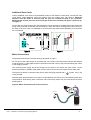
1
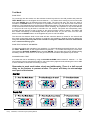
CONTENTS
SECTION 1 – INTRODUCTION
Page 4
About this manual
Page 4
System design and planning
Page 4
Panel types
Page 4
General
SECTION 2 – INSTALLATION
Page 4 – 5
Page 5
General
Page 5
ESD Precaution
Page 6
Cable Types and Limitations
Page 6
Mains Wiring
Page 6
Planning the Cable Layout in the Panel
Page 7
Fixing the Cabinet
Page 7
Additional Zone Cards
Page 8
Mains Connections
Page 8
Circuit descriptions and wiring details
Page 9
Main control pcb (PCENV-M-5)
Page 9
Single zone hy-spec card (PCENV-1Z-5)
Page 9
Three zone budget card (PCENV-3Z-5)
Page 9
Drawing S1597 – general schematic
Page 10
Drawing S1598 – Twin Wire connections
Page 11
Drawing S1599 – three wire connection
Page 12
Drawing S1600 – repeater connections
Page 13
Drawing S1601 – detector base connections
Page 14
SECTION 3 – ENGINEERING OPTIONS
General
Page 15
Page 15
Main control pcb (PCENV-M-5)
Page 15
Single zone hy-spec card (PCENV-1Z-5)
Page 16
Three zone budget card (PCENV-3Z-5)
Page 16
Envoy Installation, Commissioning & Operating Manual
2
CONTENTS
SECTION 4 – COMMISSIONING
Page 17
General
Page 17
Powering the Panel
Page 17
Connecting the Battery
Page 17
Disposal of Batteries
Page 17
Initialisation of Zone Cards
Page 18
Twin Wire Operation
Page 19
Zone Circuits
Page 20
Sounder Circuits
Page 20
Three Wire Circuits (budget pcb only)
Page 20
SECTION 5 – FAULT FINDING
Page 21
General
Page 21
Fault Latch
Page 21
Fault Finding Chart
Page 22
SECTION 6 – TECHNICAL DATA
Page 23 – 24
SECTION 7 – NETWORKING
Page 25
Network philosophy
Page 25
Limitations
Page 25
Installing PCENV-NET
Page 25
Set up network
Page 26
Network control and operation
Page 26 – 27
Drawing 1831M – 4 panel network connection
Page 28
Drawing 1832M – Installing PCENV-NET
Page 29
SECTION 8 – OPERATOR INSTRUCTIONS
Controls and Indications
Test Mode
Page 30
Page 30 – 32
Page 33
Zone Test
Page 33
Zone Test Without Sounders
Page 33
Sounder Walk Test
Page 33
Disable Zones or Sounders
Page 34
Routine Maintenance and Testing
Page 35
USER INSTRUCTIONS
Envoy Installation, Commissioning & Operating Manual
3
SECTION 1 – INTRODUCTION
About This Manual
This manual is intended as a complete guide to the 1 to 4 zone range of conventional Surveyor ENVOY
fire alarm control panels. Installation instructions are provided in the first part of the manual with the
following sections dealing with commissioning, full technical details and operating procedures.
A
separate Log Book is also provided.
System Design and Planning
It is assumed that the system, of which this control panel is a part, has been designed by a competent
fire alarm system designer in accordance with BS 5839-1:2002 and with regard to BS EN 54 parts 2 and
4 in the case of control equipment and power supplies. Design drawings should be provided to clearly
show the position of any field devices and ancillary equipment.
Panel Types
FCPENV-1
A single zone, non extendable control panel with an integral 1.0 Amp PSU and space for 2 x 12V S.L.A
batteries. Cabinet size: 277mm Wide x 200mm High x 97mm Deep
FCPENV-1EXT
A single zone control panel with the capacity to be extended up to 4 zones via plug in zone cards.
Integral 1.0 Amp PSU and space for 2 x 12V S.L.A batteries. Cabinet size: 400mm Wide x 200mm High
x 97mm Deep.
FCPENV-1EXT-L
As above but in larger cabinet to allow batteries to be fitted without removing the PCB. Cabinet size:
400mm Wide x 300mm High x 97mm Deep.
General
The control panel is a micro-processor controlled, conventional fire alarm control system, comprising of
one circuit board, plus add on modular circuit boards, for additional zones (extendable version only).
The enclosure consists of back box and hinged, removable lid. Constructed of 1.2mm (18swg) zintec
mild steel and powder coated in textured light grey. The enclosure is designed to give protection to IP30
level.
Control panels are available from 1 to 4 zones. They are supplied as a one zone non extendable
control panel or a one zone extendable control panel. The panel is extended using either the hy-spec
single zone cards, which consist of one zone, one sounder circuit and one aux relay, or a three zone
budget zone card which consists of just three zones on a single card plus zone +ve for 3 wire
connections.
A 4 zone repeater is available and requires one core per zone plus three additional cores.
These panels are designed to comply with the requirements of BS EN 54 part 2 1998, but include
integral facilities to enable connection to older systems, which may not comply with current standards.
Envoy Installation, Commissioning & Operating Manual
4
General – Continued
The control panels are compatible with a wide range of detection and alarm devices. Refer to technical
specification for details. The panel can be, CONVENTIONAL with separate detection and alarm circuits
or “TWIN-WIRE“, with detectors and sounders on the same circuits. This is selectable internally and can
be set differently for each zone if using the hy-spec single zone extension cards. The ENVOY control
panel has integral detector removal monitoring and no special active end of line units are required.
ENVOY control panels are simple to install and operate. Control functions are enabled by keyswitch.
The panel fascia is retained by a security cam lock . No internal access is required under normal usage.
SECTION 2 – INSTALLATION
General
•
The installation of fire detection and alarm systems should be carried out in accordance with
B.S.7671, IEE wiring regulations and in line with B.S.5839 British Standard codes of practice for
fire alarm installations. The installation should be carried out by suitably qualified and
experienced technicians.
•
Care should be taken with regards to avoiding the close proximity of high voltage cables or areas
likely to induce electrical interference. Earth links should be maintained on all system cables and
grounded in the control panel.
•
Any junction boxes used should be clearly labelled FIRE ALARM.
•
Any ancillary devices, e.g. door retaining magnets, must be powered from a separate power
source.
•
Any coils or solenoids used in the system must be suppressed, to avoid damage to the control
equipment.
Envoy Installation, Commissioning & Operating Manual
5
ESD PRECAUTION
Electronic components are vulnerable to damage by Electrostatic Discharges (ESD). An ESD wrist
strap, suitably grounded, should be worn at all times when handling pcbs. These wrist straps are
designed to prevent the build up of static charges, not only within a persons body, but on many other
materials. ESD damage is not always evident immediately, faults can manifest themselves at anytime in
the future.
All pcbs should be stored in static shielded bags (silvered) for safe keeping, when not mounted in the
control panel. Do not use “black” or “pink” bags and never allow pcbs to come in contact with bubble
wrap or expanded polystyrene (packing chips).
Static shielded bags and disposable wrist straps are available from the manufacturer.
!
Warning, Control Panel Access Keys
The keys to the control panel must be kept, safely, by a responsible person. Hazardous voltages may
be present. Access to the inside of the panel is not normally required. Disconnect mains supply prior to
opening cabinet.
Cable Types and Limitations
To comply with EMC (Electro Magnetic Compatibility) regulations and to reduce the risk of electrical
interference in the system wiring, we recommend the use of screened cables throughout the installation.
Acceptable, commonly available, screened cables, which can be used on both the sounder and detector
circuits include NoBurn™, FP200™, Firetuff™, Firecel™, or any other cable complying with BS 6387
categories C, W, Z.
Mains Wiring
The mains supply to the fire alarm panel should be hard wired, using suitable three core cable (no less
than 1.0mm2 and no more than 2.5mm2) or a suitable three conductor system that meets the
appropriate national wiring regulations. The panel should be fed from a double pole, isolating, switched,
fused, spur, fused at 3A. This should be secure from unauthorised operation and be marked ‘FIRE
ALARM: DO NOT SWITCH OFF’. The mains supply must be exclusive to the fire panel.
As an alternative to a switched fused spur, a double pole isolating device may be used (see diagram)
providing it meets the appropriate national wiring regulations.
NOTE: Any isolating device used, must have a minimum 3mm contact gap.
Envoy Installation, Commissioning & Operating Manual
6
Planning the Cable Layout in the Panel
The detector and sounder circuit cabling is classed as extra low voltage and must be segregated away
from mains voltages. Careful planning is needed to ensure this, refer to Figure 1 (below) for guidance
and important information on how to remove the panel’s knockouts. Always ensure that if a knockout is
removed, the hole is filled with a good quality cable gland. Any unused knockouts must be securely
blanked off.
Figure 1 : Location of knockouts for cable entry and knockout removal details
Fixing the Cabinet
Remove outer cover by unlocking the door, drop down fully, remove Earth connection, slide lid to the
right, then pull gently towards you. Disconnect transformer and earth connections at top l/h corner of
PCB using small terminal driver. The terminals are marked ac (white wires) and Earth (green and
yellow wires). Remove circuit board from back box by unscrewing 3 in number M4 cross headed screws
from the circuit board supports. Place circuit board, lid and fixings in a safe position.
Secure cabinet to the wall using the four indented holes in the back box (see figure 2). Ensure that the
box is mounted in a convenient location where it may be easily operated and serviced and where it is
away from possible sources of vibration or shock, i.e., on partition wall next to a slamming door.
External cables should be glanded via pre-formed knockouts at the top and rear of the box as provided.
The enclosure should be cleaned of swarf etc., prior to refitting of printed circuit board.
Disconnect the battery leads from the circuit board by a pull out connector at the top l/h corner of the
PCB. Insert batteries and connect the battery leads to the battery terminals before replacing circuit
board. Ensuring the white link lead is also connected.
Figure 2 : Fixing the cabinet
(Drawing shows model FCPENV-1
with 2 x 4.5Ah, 12v batteries).
(Models FCPENV-1EXT and
FCPENV-1EXT-L have space for
up to 2 x 7.0Ah, 12v batteries)
Envoy Installation, Commissioning & Operating Manual
7
Additional Zone Cards
If fitting additional zone cards to the extendable version of the ENVOY control panel, first refit the main
circuit board. Slide additional cards into position using the locating pins, see figure.3. Particular
attention must be made to ensuring that the pins are located correctly in the connector.
Misalignment of these pins will result in damage to the zone card when the panel is powered up,
see figure.4.
Fix the card into position using clips and self tapping screws provided. Pre-drilled fixing holes have been
made in the mounting rail but they are obscured by a foam strip which is designed to protect tracks on
the back of the zone card. It is advisable to locate these fixing holes before attempting to screw down
the circuit board.
Mains Connections
The general requirements for mains wiring is described on page 6.
Do not connect the mains supply to the panel until you are fully conversant with the layout and features
of the equipment. A rating plate is fitted in the bottom left hand corner of the panel describing the nature
of the supply permitted.
The incoming mains supply should be brought into the panel in the bottom left hand corner, via the
knockout provided. A suitable cable gland must be used to secure the outer sheath of the cable used.
The earth must first be connected to the primary earth stud (peg) marked with a
crimp provided.
symbol using ring
Sufficient earth lead should be left to allow Live and Neutral connections to be accidentally pulled from
terminal block, while leaving earth connection intact. Secondary earths may be connected to the brass
earthing block.
Figure 5: Mains block and earth stud connections
N
L
Earth Stud
Mains Supply
Input Cable
Envoy Installation, Commissioning & Operating Manual
8
Circuit Descriptions and Wiring Details
MAIN CONTROL PCB (PCENV-M-5)
SNDR 1 & 2
2 conventional monitored sounder circuits, 28vdc reverse polarity monitored,
4K7 end of line. SNDR 1 can be selected to function as a “TWIN-WIRE” zone via
SW5 on DIL switches. Both circuits fused at 500mA. Maximum panel sounder
load 1 Amp.
ZONE 1
Conventional 2 wire zone with in built detector removal monitoring. Can be used
with zener diode type bases by via SW3 on DIL switches. Maximum detector
load 3mA. 4K7 EOL
MON I/P
Evacuate input, monitored for short and open circuit faults. Silenceable, non
latching. Requires 470 Ohms to activate. 4K7 EOL
OUTPUT FR / FLT
Switched –ve outputs, common fire and common fault. Maximum load 100mA
-VE INPUTS:SIL
Switched –ve input. When grounded provides remote silence alarms.
RES
Switched –ve input. When grounded provides remote reset.
P
Precinct or class change switched –ve input. When grounded activates sounder
circuits. Non latching, non silenceable
REM FLT
Clean c/o contacts, fail safe, unfused, maximum load 1 amp @ 50vdc
REM FIRE
Clean c/o contacts, unfused, maximum load 1 amp @ 50vdc
28v DC OUTPUT
Fused 500mA 28vdc supply output for powering relays etc. Not recommended
for door retainer supply.
SINGLE ZONE HY-SPEC CARD (PCENV-1Z-5)
ZONE
Conventional 2 wire zone with in built detector removal monitoring. Can be used
with zener diode type bases via SW3 on DIL switches. Maximum detector load
3mA. 4K7 EOL
OPR
Switched –ve zone repeater output. Maximum load 100mA
SNDR
Conventional monitored sounder circuit, 28vdc reverse polarity monitored, 4K7
end of line. Can be selected to function as a “TWIN-WIRE” zone via SW5 on DIL
switches. Fused at 500mA. Maximum panel sounder load 1 Amp.
AUX RELAY
Clean c/o contact, fused @ 500mA. Common fire or zonal operation selection
via SW4 on DIL switches.
THREE ZONE BUDGET CARD (PCENV-3Z-5)
ZONES 1 – 3
Conventional 2 wire zones with in built detector removal monitoring. Can be
used with zener diode type bases via SW3 on DIL switches. Maximum detector
load 3mA. 4K7 EOL
OPR
Switched –ve zone repeater output. Maximum load 100mA
ZP+
Common zone +ve for operation of 3 wire circuits. Maximum load 1amp @
28vdc
Envoy Installation, Commissioning & Operating Manual
9
WARNING:- Not all makes of detectors and call points etc are suitable for this panel, see page 24 for
recommended equipment
Drawing No. S1597, showing general wiring schematic
Envoy Installation, Commissioning & Operating Manual
10
WARNING:- Specific detectors and call points etc must be used with “TWIN-WIRE“ systems, see page 24
for details
Drawing No. S1598, showing wiring schematic for ‘TWIN-WIRE’ connections
Envoy Installation, Commissioning & Operating Manual
11
WARNING:- Not all makes of detectors and call points etc are suitable for this panel, see page 24 for
recommended equipment
Drawing No. S1599, showing general wiring schematic for PCENV-3Z-5, including 3 wire connection
A typical 3 wire circuit is shown on Dwg No. S1599, connected into zone 2. This method of wiring does
not meet current standards for new systems, but may be suitable for upgrading certain existing
installations.
Three wire circuits may contain high current and / or unpolarised sounders or other unsuitable
equipment, so care should be taken to upgrade equipment when connecting in these circuits.
CAUTION: Ensure all solenoids, relays and sounders fitted to the circuits are polarised and
suppressed with back EMF diodes. It is recommended that old heavy current sounders are
changed to light current. Maximum sounder load on the total 3 wire system is 1 Amp.
The following modifications must be made for the circuit to function correctly:
•
The detector zone must be configured for short = fire and no head removal monitoring by switching SW4 on DIL switches. Refer to Engineering Options.
•
The sounder circuit is not monitored, therefore a 4K7 resistor must be fitted to the sounder circuit
terminals in the panel.
Envoy Installation, Commissioning & Operating Manual
12
Drawing No. S1600, showing repeater panel connections
Envoy Installation, Commissioning & Operating Manual
13
Drawing S1601, showing detector base connections
Envoy Installation, Commissioning & Operating Manual
14
SECTION 3 – ENGINEERING OPTIONS
General
The panel has various options which are programed by the selection of DIL switches on the PCBs. This
section explains which switch relates to which option.
PCENV-M-5 (Master PCB)
Switch
Function when ‘off’
Function when ‘on’
1
Zone 1 latching
Zone 1 non latching
2
Short circuit = fault, zone 1
Short circuit = fire, zone 1
3
Detector removal, standard Schottky diode Zener diode head removal
base
4
Rem.fire relay, is common
Rem fire relay, zone 1 only
5
Conventional operation (2 wire zone, 2
wire sounders)
Twin wire operation SNDR 1 (Two wires share
sounders and detectors)
6
Zone 1 operates all sounder circuits
Zone 1 no sounder circuits, panel buzzer only
7
Zone 1 operates all aux relays
Zone 1 does not operate Rem.fire aux, still
operates other aux relays
8
Sounder operation common
Zone of origin continuous, other sounder circuits
pulsing (PCENV1Z-5 cards only)
Envoy Installation, Commissioning & Operating Manual
15
Engineering Options Continued
PCENV-1Z-5 (hy-spec single zone card)
Switch
Function when ‘off’
Function when ‘on’
1
Zone latching
Zone non latching
2
Short circuit = fault
Short circuit = fire
3
Detector removal, standard Schottky
diode base
Zener diode head removal
4
Zone operates all aux relays
Zone operates own aux relay only
5
Conventional operation
Twin wire operation, use SNDR CCT
PCENV-3Z-5 (Three zone budget zone card)
Switch
Function when ‘off’
Function when ‘on’
1
Zone 2 latching
Zone 2 non latching
2
Zone 3 latching
Zone 3 non latching
3
Zone 4 latching
Zone 4 non latching
4
Zones 2-3-4 short circuit = fault
Zones 2-3-4 short circuit = fire
5
Zones 2-3-4 detector removal, standard
Schottky diode base
Zones 2-3-4 zener diode head removal
Envoy Installation, Commissioning & Operating Manual
16
SECTION 4 – COMMISSIONING
General
The commissioning procedures should be completed one step at a time as described below to avoid
unnecessary problems. By following a logical sequence any faults that may occur can be quickly
identified and rectified before moving on to the next step.
Before connecting external circuits to the control panel it is recommended that the panel is powered up
and tested, and any faults cleared before proceeding.
Ensure that 4K7 resistors are fitted into zone and sounder circuit terminals (see drg.no. S1597 on page
10) before applying power.
To clear the battery fault indication when the mains is connected, a battery must be connected to the
battery terminals; it is not possible to inhibit the battery fault by the insertion of a resistor.
The system may be operated on the battery supply, i.e. if the mains supply is not available.
Powering the Panel
Remove the fuse from the mains input. Connect the supply wiring to the terminal block. Check that all
connections are sound and that 4K7 EOL resistors are fitted to zone and sounder circuits.
Refit the fuse and switch on the mains supply. The panel LEDs are illuminated momentarily, the ARW
LED remains lit and a battery fault is indicated. The internal buzzer sounds.
Connecting the Battery
The standby battery comprises two 12V cells of a capacity suitable for the required standby period and
total alarm load.
Batteries may be located in the panel or in a separate cabinet depending on the battery size.
Battery leads are provided, including a battery link.
The SUPPLY HEALTHY LED should now be illuminated. The ARW LED should be illuminated and the
internal buzzer pulsing.
Turn the CONTROLS keyswitch to ON, and press RESET.
All the LEDs are lit momentarily, the ARW LED should extinguish and the buzzer should be silent. The
panel is now operating correctly in the quiescent mode.
Any faults that are indicated at this stage should be investigated and cleared before proceeding. If
necessary refer to the fault location chart on page 22 for further information.
If unfamiliar with the Surveyor ENVOY Series equipment, it is advisable to explore the panel operation
and become conversant with the controls before proceeding. Faults can be simulated by open and
short circuiting zone and sounder circuits, fire alarms can be generated by shorting the zone terminals
with a 470R resistor. Refer to the Operation section if required.
Disposal of Batteries
Respect the environment. Batteries must be disposed of responsibly and in accordance with any local regulations.
Envoy Installation, Commissioning & Operating Manual
17
Initialisation of Zone Cards
For added security, the master card (PCENV-M-5) keeps a log of fitted zone cards and will indicate a
system fault, with a warbling tone, if zone cards are removed, or cease to function. To achieve this,
zone cards are logged ‘on’ and ‘off’ of the panel.
Proceed as follow:
1
Ensure panel is completely powered down by disconnecting both mains and battery supplies.
2
Insert, or remove, required zone card(s), ensuring pins are securely located.
3
Press and hold button No.1 on keypad and at the same time apply either battery or mains power.
4
Observe the zone fault illuminating on each zone card, this indicates acknowledgment of
‘learning’ mode.
5
Release button 1 and press Reset to clear fault indications and ‘ARW’.
If a panel should start to warble and show system fault, check the following:•
If a PCENV-NET card is fitted, refer to network instructions.
•
If no network is present, check whether zone cards will function i.e. go into fire, or fault.
•
If a zone card appears to be faulty, replace it, or remove it.
•
If a problem persists, try to re-log the card by following the procedure 1-5 again, as above.
•
If ‘Disablement’ indicator is on, but no zone is illuminated, it is possible that the internal memory is
out of synchronisation. This can be corrected by the following procedure:
1
Completely power down panel
2
Press and hold button No.2 on keypad whilst powering up
3
The panel will enter a self diagnosis mode, which resets the memory
4
Pressing the ’Enter’ button will step through a test routine, which will operate LEDs and outputs in
a sequence.
To exit this mode, power down the panel and power up again, as normal.
Envoy Installation, Commissioning & Operating Manual
18
Twin Wire Operation
The panel can be converted to ‘Twin Wire’ operation by selecting Dil switch 5 on each zone card (hyspec zone cards only). Any individual zone, or all zones , can be selected as twin wire. The twin wire is
designed to operate with polarised 470R call points, Apollo and Hochiki ‘SAV-WIRE’ bases only. See
page 24 for part No.s. Any standard 24v bell, siren or strobe, that is polarised and suppressed can be
used, providing sounder o/p limits are not exceeded. Short circuit as fire and non latching zones cannot
function on a twin wire zone. When twin wire operation is selected, the conventional zone circuit is
disabled by the software. The sounder CCT terminals should be used for connection of detectors, call
points and sounders.
When used as a twin wire system, use sounder 1 on the main card (PCENV-M-5) and remove the 4K7
resistor in sounder 2, to enable correct monitoring, as these circuits work in tandem.
Where a single zone twin wire system is installed (normally non compliant) and two sounder outputs are
required the following modification can be employed:
Remove both 4K7 EOL resistors from SNDR 1 and 2 and substitute with 10K ohm resistors (or 2 x 4K7
in series). This enables sounders and / or detectors to be used on both legs to provide 2 monitored
circuits on one zone, thus enabling full compliance for twin wire, with only one zone.
Envoy Installation, Commissioning & Operating Manual
19
Zone Circuits
The default mode of operation assumes that the zone circuit is configured for open and short circuit fault
monitoring, and detector removal monitoring, i.e. detector bases are fitted with a diode.
If these conditions do not apply, e.g. when connecting a circuit from an existing system, the operating
parameters for each affected zone must be changed. Refer to the Engineering Options section for
details.
It is recommended that each zone is connected in turn and its operation proved before moving on to the
next zone.
Check that all detectors are fitted into their bases and that a 4K7 Ohm resistor has been fitted to the last
device. Remove the 4K7 Ohm resistor from the selected zone terminals and connect the zone pair,
observing polarity.
If a zone fault is indicated, investigate and clear before proceeding to the next circuit. If necessary refer
to the fault location chart on page 22.
Continue to connect each zone circuit until all are connected and fault free.
It may be preferable to test the operation of zone devices before proceeding with the connection of
sounders.
Sounder Circuits
The Master PCB has two sounder circuits and each hy-spec zone card has one sounder circuit that by
default operate in “constant sounder” mode on the activation of any zone. “ Zone of origin operation”
can be achieved by changing the operating parameters. Refer to Engineering Options.
Sounders must be polarised and suppressed and connected in a parallel circuit with no spurs or tees.
Ensure that the load of the sounders is within the individual circuit limits, and that the total load does
not exceed the panel limits, taking into account any additional load imposed by auxiliary circuits,
repeaters, etc.
Remove the 4K7 Ohm resistor from the relevant sounder circuit terminals and connect the circuit pair,
observing polarity. Ensure that a 4K7 Ohm resistor is fitted in parallel with the last device on the circuit.
Clear any faults before proceeding – refer to the fault location chart on page 22 if necessary.
Sounders can be tested by operating the SOUND ALARMS push button.
Three-wire Circuits (budget pcb only)
A typical connection for a three-wire circuit is shown in drg. no. S1599 (page 12); however, the following
modifications need to be made for the circuit to function correctly:
•
The detector zone must be configured for Short = Fire, unless the circuit is compatible with
open and short circuit monitoring, i.e. detectors with an alarm impedance of > 100 Ohm and <
700 Ohm are fitted, and call points are fitted with a 470 Ohm series resistor. Refer to
Engineering Options.
•
In these circumstances the sounder circuit is not monitored, therefore, a 4K7 Ohm resistor must
be fitted at the sounder circuit terminals.
Envoy Installation, Commissioning & Operating Manual
20
SECTION 5 – FAULT FINDING
General
A fault is indicated by the illumination of the SYSTEM FAULT LEDs and a buzzer tone. Specific faults
are identified by additional fascia indicators, e.g. zone fault. The buzzer tone varies depending on the
fault and may, or may not, be silenceable.
Fault Latch
If an intermittent fault exists it is possible to make all fault indications latch to help identify problems. To
activate fault latch press the TEST MODE button and then the ENTER button. The Test Mode LED will
be lit but no buzzer sounds. Any faults occurring while this mode is active will be latched until the
RESET button is pressed. Pressing RESET at any time will exit fault latch mode.
Envoy Installation, Commissioning & Operating Manual
21
Fault Finding Chart
The following chart identifies the indications that may be displayed, with the possible cause and the
recommended action. Fault location should be tackled logically by isolating fault paths until the source
is apparent, e.g. disconnecting zone and sounder circuits to prove if the fault is on the circuit or in the
panel, etc. Faults on external circuits can be traced by breaking down the circuit, e.g. placing the EOL
at the mid point of the circuit and determining which half is affected.
Panel
Indication
Possible
Cause
Action
Supply Healthy extinguished.
No other indications
Mains failure & Battery failure
Check supply / fuse
Check battery / fuse
Change batteries
Apply Mains
System Fault
+ PSU fault
Mains failure/fuse failure
Battery disconnected or open circuit.
Battery Fuse failed
Voltage too high (>30V) or too low
(<19V)
Check supply / fuse
Check battery / fuse
Adjust to 27.6V. Measure voltage using the battery terminals on pcb, with the batteries disconnected.
System Fault
+ Earth fault
One or more cables in contact with earth Disconnect ext. cables until fault clears. Investigate circuit
and rectify. If fault persists with all circuits disconnected,
then fault is on PCB. Replace. Hint: Remove the pcb to
earth block earth wire, if the fault dissapears then you have
an earth fault. If not the fault is on the pcb.
System Fault
+ Sounder fault
Sounder circuit open circuit (LED slow Check circuit integrity/EOL
pulse) or short circuit (LED fast pulse) Sounder not polarised or reverse polarity – correct fault
System Fault
+ Zone Fault
Zone open circuit (LED slow pulse)
Zone short circuit (LED fast pulse)
Confirm fault is on external circuit by disconnecting zone
wires and fitting 4K7R in zone terminals. Check EOL and
circuit connections
System Fault
+ Zone Fault
+ Detector
Removed
One or more detectors removed
Base(s) wired incorrectly
Incompatible detector(s)
Panel faulty
Replace detector(s)
Check wiring/diodes
Consult supplier
System in Test Mode
Test Mode
+ Zone Fault or Detector Removed
Reset system to exit test mode
ARW
Illuminates when panel is first
powered up.
Internal microprocessor has auto
reset due to spurious power
surge/interference
Reset panel. If condition
persists, consult supplier
Zone Disabled
Zone isolated
Re-instate zone (refer to
programming if necessary)
Envoy Installation, Commissioning & Operating Manual
22
SECTION 6 – TECHNICAL DATA
•
•
•
•
Mains input voltage ; 230Vac, 50-60 Hz (Harmonised) +10% to -15% compliant with BSEN54
Pt4 : 1997 for fire alarm power supplies.
Nominal system voltage 24V dc.
Power supply : Current limited 1amp suits SLA batteries only. Charging voltage 27.6 volts +/0.2V
Temperature range: -5 to +40oC. Maximum relative humidity = 95%
GENERAL DATA & CURRENT CONSUMPTION FIGURES
Part No
Description
Qty
Conventional
Sndr ccts
Qty
Total Quiescent
TWIN
Sndr
Current
WIRE
Load
Zone/Sndr (Amps)
ccts
Panel
Only in
Alarm
FCPENV-1
Compact non
extendable
2
2
1
57mA
100mA
FCPENV-1EXT
Extendable version
2
2
1
57mA
100mA
FCPENV-1EXT-L Extendable version,
large cabinet
2
2
1
57mA
100mA
PCENV-1Z-5
One zone hy-spec
extension zone card
1
1
-
19mA
56mA
PCENV-3Z-5
Three zone budget
extension zone card
-
-
-
28mA
35mA
BATTERY SIZES
The panels have space for the following batteries, based on standard sizes as supplied by the manufacturer.
Part No.
Batteries
FCPENV-1
Cabinet Size: 277W x 200H x 97D mm
Weight: 3.36Kg (without batteries)
2 x 1.2Ah 12 Volt SLA
2 x 2.0Ah 12 Volt SLA
2 x 4.5Ah 12 Volt SLA
FCPENV-1EXT
Cabinet Size: 400W x 200H x 97D mm
Weight: 4.2Kg (without batteries)
2 x 1.2Ah 12 Volt SLA
2 x 2.0Ah 12 Volt SLA
2 x 3.0Ah 12 Volt SLA
2 x 4.5Ah 12 Volt SLA
2 x 7.0Ah 12 Volt SLA
FCPENV-1EXT-L
Cabinet Size: 400W x 300H x 97D
Weight: 4.9Kg (without batteries)
As Above
Envoy Installation, Commissioning & Operating Manual
23
Technical Data Continued
Detector Zones:
Voltage 17 – 28V dc. Quiescent current 3.5mA each. End of line value 4K7 Ohm.
Schottky diode or zener clamp detector removal monitoring.
Sounder
Circuits:
17 – 28V dc reverse polarity monitored. Sounders must be polarised and
suppressed. End of line value 4K7 Ohm. Output current 500mA. Maximum shared
sounder load 1.0 amp.
Fuses:
Mains: F2AH, 250VAC, 20mm HBC Ceramic. Compliant with IEC (EN 60127 A2)
Battery: 1 amp, nanofuse, fast acting
Supply: 1 amp, nanofuse, fast acting
Sounders: 500mA, nanofuse, fast acting
SUITABILITY (RECOMMENDED EQUIPMENT)
Conventional:
Twin-Wire:
Smoke / Heat Detectors Nittan: Evolution Range
UB-4SD schottky diode base
Call Point
Sounders
Apollo: Series 65
45681-201 schottky diode base
Apollo: Series 65
45681-206 base
Hochiki: CDX Range
YBN-R-6SK schottky diode base
Hochiki: CDX Range
YBO-R-6PA base
KAC:
MCP1A-R-470, 470 OHM Resistor
KAC:
MCP1B-R-TW, Polarised & 470 OHM
Fulleon:
CXL-U-R-BB, 470 OHM Resistor
Fulleon:
CX-G-R-TW, Polarised & 470 OHM
Use polarised and suppressed, light Use polarised and suppressed, light
current 24vdc electronic sounders or current 24vdc electronic sounders or
bells (Fulleon, Besson etc.)
bells (Fulleon, Besson etc.)
Envoy Installation, Commissioning & Operating Manual
24
SECTION 7 – NETWORKING
A feature of the Envoy is the ability to provide 2 wire (RS 485) communications for repeating and
networking capability. All standard panels of verion 5.0 and above can be networked.
The PCENV-NET is an ‘add-on’ card which provides the RS 485 interface and address switches. A
PCENV-NET is required for each panel in the network. Up to four panels can be networked. A ‘comms’
terminal is provided on the master pcb as standard (although this is not shown on the schematic
diagrams on the previous pages), but this terminal is not active without the network card fitted.
Network Philosophy
Up to four standard panels can be connected. 1 way or 3 way zone cards can be used in any
combination. Ideally on a four zone system, four indicating zones must be available.
Several interesting scenarios can be achieved:
1.
A simple panel with up to three repeaters
2.
Connect two zones on one panel two on the other and both panels will show all four zones
3.
Connect one zone on each of four panels and display all zones on all panels
4.
Have zones on one panel and sounders on another
Other permutations are possible.
Limitations
The system is limited to four zones, although sixteen could be connected, only four can show at one
panel. For example, when zone 1 is put into fire, it will display as zone 1 on all panels regardless of
which panel zone 1 wiring is connected to.
Installing PCENV-NET
1.
Turn off power to panel
2.
Remove PCENV-M (Master pcb)
3.
Locate mounting hole and fit small 3mm threaded spacer (supplied) to PCENV-M. Make sure
insulated washer (supplied) is used under screw head.
4.
Plug in PCENV-NET to 10 way header, (see drawing1832M) ensure alignment with small spacer
and check all connector pins are aligned correctly.
5.
Fit screw through PCENV-NET into spacer and tighten to secure pcb.
6.
The communications cable is connected to ’comms’ terminals at top of pcb (see drawing 1831M)
Envoy Installation, Commissioning & Operating Manual
25
Set Up Network
Once all cards are fitted , set Dil switch addresses on PCENV-NET. Designate one panel as the
‘master’
Dil switch positions:Both off
1 off 2 on
1 on 2 off
1 on 2 on
=
=
=
=
Master
First repeater / panel
Second repeater / panel
Third repeater / panel
Each panel must have a different setting.
For monitoring purposes, the master must be instructed how many panels are in the network. If it
changes, the panel will show system fault and will warble.
To enter quantity of panels:
At the master panel (panel with both address switches ‘off’)
1.
Turn off power to panel
2.
Press and hold button 4 on keypad whilst powering panel back up. (when powered up the panel
will beep continuously)
3.
Enter total number of panels in the network, including the master, by pressing the relevant
keypad number (1-4), followed by the enter button.
When all panels are addressed correctly, the master is set-up and all panels are powered, the TX and
RX LEDs will flicker on all panels to confirm communication between panels. In the event of a ‘comms’
failure the affected panels will warble and show a fault. Note:- panels will function as stand alone in the
event of ‘comms’ failure.
Network Control and Operation
As standard, the network / repeater panels are configured to provide basic operation. If non standard
functioning is required, please contact our technical department for advice.
The table below details the functionality of the system.
Local
Global
=
=
Operates and displays at the local panel level only
Operates and displays on all panels simultaneously
=
=
=
=
=
=
=
=
Local ‘panel controls’ only
Global
Global, silence alarms and fault tone
Global
Local zones only
Local zones only
Local
Local fault mute (without key-switch)
Controls
Key switch
Evacuate
Silence
Reset
Test Mode
Disable
Test LEDs
Enter
Envoy Installation, Commissioning & Operating Manual
26
Network Control and Operation Cont’d
Indications
Common fire
Common fault
Zones 1 – 4
=
=
=
Global fire indication
Global fault indication
Global zone indication
All other indications work at the local level
Option Switches
As a rule, all option switches function at the local level only, e.g. if on panel A the option switch No. 8
(zonal bells) is selected ‘on’, this will cause sounders on panel B, C & D to pulse when the fire is on
either B, C or D panels.
The sounders on panel A will sound continuously only when an alarm is received from one of ‘A’s
zones.
With due consideration at the design stage, networking could provide useful solutions.
Please contact our technical department for further advice.
IMPORTANT: ENSURE THAT ALL PROGRAMMING IS CORRECT BY CONDUCTING A
FUNCTIONAL TEST ON THE COMPLETE FIRE SYSTEM
Envoy Installation, Commissioning & Operating Manual
27
Drawing No. 1831M, showing typical network, 4 panel connection
Envoy Installation, Commissioning & Operating Manual
28
Drawing No. 1832M, showing network card installation
Envoy Installation, Commissioning & Operating Manual
29
SECTION 8 – OPERATOR INSTRUCTIONS
Controls and Indications
SEE TABLE 1
Buttons on keypad will not operate unless the
Activate Controls key-switch is in the ON position.
SEE TABLE 2
Envoy Installation, Commissioning & Operating Manual
30
Controls and Indications Continued
TABLE 1
A
SUPPLY HEALTHY
Indicates permanently when panel is correctly powered.
B
TEST MODE
Pulses when the control panel is in engineer’s test mode. The individual
circuit fault lamp will be on (steady) whilst the circuit is in test mode. It is not
possible to test a disabled zone. See page 33 “Test Mode” for more details.
C
DISABLED
Indicates when a zone or sounder circuit has been disabled using the disable
button on the keypad. The LED pulses when disablement mode is selected
and remains on steady if any disablement is present on any of the circuits.
The individual circuit fault lamp will be on (steady) whilst the circuit is
disabled. See page 34 “Disable Zones or Sounders” for more details.
D
ARW
Automatic Reset Warning, Indicates if the processor has been rebooted. Will
indicate when panel is first powered up. See fault finding section for more
details.
E
“ENABLE CONTROLS” KEYSWITCH
Key-switch to activate the buttons on the keypad. They do not function unless
this switch is in the on position
F
POWER SUPPLY FAULT
Indicates a fault with the power supply. A fast pulse = battery fault. A slow
pulse = voltage faults. An intermittent blip = mains fault. Constant LED = voltage out of range. See fault finding section for more details.
G
EARTH FAULT
Indicates an earth fault on the system. See fault finding section for more
details.
H
REMOTE OUTPUTS ACTIVATED
Indicates if the remote fire and fault relays have been activated
I
REMOTE OUTPUTS FAULTY /
DISABLED
Indicates if the remote relay outputs are faulty or have been isolated using
the isolate remote button on the keypad. This LED also indicates short or
open circuit faults on monitored input. Slow pulse = open circuit. Fast pulse =
short circuit.
J
DETECTOR REMOVED ON ZONE
Indicates that a detector has been removed on this zone. See fault finding
section for more details.
K
SOUNDER CIRCUIT FAULT
Indicates that there is a fault on the individual sounder circuit or that the
sounders have been disabled or are in test mode. A fast pulse = short circuit.
A slow pulse = open circuit. All zonal sounder circuit fault LEDs are on
(steady) for disabled or test mode. Note:- disablement or test mode will have
priority. See fault finding section for more details.
L
COMMON FAULT
Dual LEDs Indicate when any fault occurs. Also if Test Mode is activated or if
zones or sounders have been disabled. Pulsing when fault buzzer sounding,
intermittent pulsing when fault buzzer muted (by pressing the ENTER button)
Note:- when a mains failure fault is present the LEDs blip intermittently to
conserve the batteries. See fault finding section for more details.
M
COMMON FIRE
Dual LEDs Indicate when any zone is in fire. Pulsing when fire or evacuate is
active, will steady when alarms silenced.
N
ZONE FAULT / DISABLED / IN
TEST
Indicates that there is a fault on this zone, or that the zone is in test mode, or
has been disabled. LED on (steady) in “test mode” or “disabled“. A slow
pulse = open circuit. A fast pulse = short circuit. Note:- disablement or test
mode will have priority. See fault finding section for more details.
O
FIRE ON ZONE
Indicates that there is a fire condition on this zone. Pulses when in fire, will
steady when alarms silenced. New zones in fire will pulse until silence
alarms is pressed again while the existing silenced zones will remain steady.
Envoy Installation, Commissioning & Operating Manual
31
Controls and Indications Continued
TABLE 2
P
TEST MODE
“Test mode” button. Puts zones into test mode. See relevant section, page
33.
Q
DISABLE
“Disable” button. To disable or isolate zones or sounder circuits. See relevant
section, page 34.
R
TEST LEDs
Pressing this button will cause all LEDs, except remote fire and fault, to
illuminate briefly.
S
ENTER
“Enter” button. Used to acknowledge selection of zone or sounder circuits for
disablement. Also mutes internal fault buzzer when active.
T
SOUND ALARMS
“Sound alarms” button. To sound all bells and activate remote fire outputs for
full evacuation.
U
SILENCE ALARMS
“Silence alarms” button. To silence bells or sounders. The internal buzzer will
still sound in the control panel until the system has been reset.
V
RESET
“Reset” button. To reset system. When the panel is in fire condition reset will
only function if the “silence alarms” button has been pressed first.
W
ISOLATE REMOTE
Isolates the remote fire and fault relays for system testing purposes. Press
again to reinstate them.
Envoy Installation, Commissioning & Operating Manual
32
Test Mode
ZONE TEST
To put zone(s) into test mode, turn the Activate Controls key-switch to the ON position and press the
TEST MODE button on the keypad. Now use buttons 1 – 4 to select which zone(s) to put into test mode
and press ENTER when all selections have been made. The test mode entry will “time out” within 5
seconds if the ENTER button is not pressed. It is possible to have any or all zones in test mode at the
same time. The Test Mode and Common Fault LEDs will be pulsing. The fault LED of the zone(s) in test
mode will be illuminated and the internal buzzer will be sounding. The operation of any smoke detector
or call point will now ring all bells or sounders for one second. The panel will automatically reset,
providing that the detector is clear of smoke or the call point glass is back in position. The alarms will
then sound momentarily to acknowledge that the panel has reset, so you can move on to the next
device. Press the RESET button on the keypad at any time to exit Test Mode.
The removal of a detector while in test mode will also cause the alarms to sound for one second and
then again momentarily when the detector is replaced, thus enabling a Detector Removal Monitoring
Walk Test. N.B the panel may take a few seconds to recognise a detector has been removed due
to it’s normal monitoring cycle.
ZONE TEST WITHOUT SOUNDERS
To test zones without the operation of any sounders, i.e. visual indications and panel buzzer only. Press
the TEST MODE button on the keypad followed by buttons 1 – 4 to select the zone(s) to put into test.
Then press the SILENCE ALARMS button and then ENTER. The sounders will now be disabled during
all testing. Should a zone which is not in test go into alarm the sounders will operate as per normal.
SOUNDER WALK TEST
A sounder test can be activated by using the SOUND ALARMS button instead of buttons 1 – 4. This
will cause the panel to sound all the bells for one second every eight seconds, allowing the user to walk
to each sounder to check that it is working correctly.
Remember to push each button slowly and deliberately. There is a half second
delay on the buttons to prevent misuse. The panel will bleep to acknowledge
each push of the button.
Envoy Installation, Commissioning & Operating Manual
33
Disable Zones or Sounders
DISABLE ZONES
To disable / isolate zones , turn the Activate Controls key-switch to the ON position and press the
DISABLE button on the keypad Now use buttons 1 – 4 to select which zone(s) to disable and then
press ENTER when all selections have been made. The disable mode will “time out” within 5 seconds if
the ENTER button is not pressed. It is possible to select any, or all zones, to be isolated at the same
time. The disable LED will be illuminated, the common fault LED’s will be pulsing. The fault LED of the
zone that is disabled will be illuminated and the internal buzzer will be sounding.
DISABLE SOUNDERS
To disable sounder circuits press the SOUND ALARMS button instead of buttons 1 – 4 (see above)
and then press ENTER. The sounder fault LED will be illuminated. It is not possible to select individual
sounder circuits.This routine will disable all sounder circuits.
To enable the zones or sounder circuits again simply repeat exactly the same procedure. WARNING
zones and sounder circuits that have been disabled cannot be enabled by the use of the RESET
button.
Remember to push each button slowly and deliberately. There is a half second
delay on the buttons to prevent misuse. The panel will bleep to acknowledge
each push of the button.
Envoy Installation, Commissioning & Operating Manual
34
Routine Maintenance and Testing
It is essential that the fire alarm installation is checked regularly by a responsible person for correct
operation in accordance with EN54 Part 2 or BS5839 Part 1. or applicable standard.
CLEANING
The exterior of the cabinet may be cleaned when required using a clean, moistened cloth. Do not use
solvents or abrasives as these will damage the panel.
ROUTINE TESTING
Routine checks should be carried out as detailed in this section of the manual. It is essential to keep the
log, in order to maintain a record of tests, checks, alarms and faults. A log book is provided with this
instruction manual. The log book should be kept with the panel and be available for inspection by an
authorised person.
DAILY
Check that the green, “SUPPLY HEALTHY“, indicator is lit. If the indicator is not lit, record the fact in the
log book and call for a qualified electrician to check the power supply.
WEEKLY
Carry out the daily check.
Operate one detector or call point on one zone and check that the panel responds to the alarm and
operates the warning devices. Record the results of the test and the zone detector/call point operated,
in the log book. A different zone detector/call point should be operated each week, to ensure that all
detectors/call points are tested in turn.
Visually inspect the batteries and all connections and ensure that they are in good condition. Visually
inspect all call points and detectors and ensure that none is, in any way, obstructed or damaged.
QUARTERLY
Check all previous entries in the log book and ensure that all necessary remedial action has been
carried out.
Carry out the daily check.
Carry out the weekly test.
Isolate the mains supply, then test that the battery is capable of operating the warning devices by
operating a detector or call point.
Reconnect the mains supply. Record the results of the tests in the log book.
ANNUALLY
Carry out the daily, weekly and quarterly tests. Test all the detectors and call points for correct
operation. Visually inspect all cable fittings and equipment to ensure that they are secure, undamaged
and adequately protected. Record the results in the log book.
EVERY 5 YEARS
Renew the sealed lead acid batteries and record the fact in the log book.
The installation requires to be tested in accordance with the testing and inspection requirements of the
Local or National Standards. Any defect should be recorded in the log book and action should be taken
to correct it.
DETECTORS
Renew or return the smoke detectors for cleaning, as directed in the manufacturer’s data, to ensure
correct operation and freedom from false alarms. Cleaning smoke detectors is a specialised activity. If
in doubt consult the supplier. Record the actions in the log book.
NOTE:
Ionisation smoke detectors contain a radioactive source and should only be disposed of in
the recommended manner. Contact your Service Company for further advice.
Envoy Installation, Commissioning & Operating Manual
35
USER INSTRUCTIONS
Alarm Condition
If all the sounders or bells are ringing, the system is in an alarm condition. YOU MUST EVACUATE
THE BUILDING OR FOLLOW YOUR NORMAL FIRE DRILL PROCEDURES.
A responsible person should then:1
2
3
4
Check the control panel to see which area or zone has caused the system to go into alarm. The
zone in alarm will be indicated by a red light on the front of the control panel, see fig 1.
Go to the area which has caused the alarm to check if a fire exists.
Only when it is safe to do so should the alarms be silenced. Turn the “activate controls” keyswitch
to the ON position and press the SILENCE ALARMS button, see fig 2. If it was a false alarm look
for the device that has caused the alarm. A detector will have a red light lit, or check to see if a
call point glass is broken. (If so replace the glass or call an engineer.)
When fully satisfied that there is no fire, return to the control panel and press the RESET button,
see fig 3. Once the system has been reset the light on the detector should extinguish and only the
green SUPPLY HEALTHY lamp should be lit on the control panel.
If the system continues to false alarm, call an engineer.
Fault Condition
If a buzzer is sounding in the control panel but the sounders or bells are not
ringing, then there is either a fault on the system or zones / sounders have been disabled. Call an
engineer.
The internal fault buzzer can be silenced by pressing the ENTER button. DO NOT RESET THE
SYSTEM UNTIL AN ENGINEER HAS INVESTIGATED THE FAULT.
See relevant section in the installation and operating manual for details of disabling and
enabling zones and sounders.