1
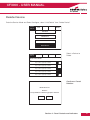
Fire
CF3000 Control Panel
User Manual
Assessed to: ISO 9001:2000
Certification number: 714h/01
Approved to:
EN54-2 1997 & A1;2006
EN54-4:1997 & A1;2002 A2:2006
Document Drg Ref: PR200-04-514-11
Marketing Ref: CC1820a
0832 – CPD – 1060
CF3000 - USER MANUAL
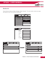
Introduction to the Manual
This manual provides information on the installation, operation and maintenance of the Cooper CF3000
System.
Notice
The operating system of the CF3000 may be revised as a result of enhancements to the system software
or hardware. Revisions to this manual will be issued and supplied on request and should be logged
in the table supplied on the contents page.
Caution
Risk of explosion if battery is replaced by an incorrect type dispose
of the used batteries according to the instructions
Contact
Technical: 01302 303350
Service: 01302 303352
Sales: 01302 303303
2
CF3000 - USER MANUAL
Contents
y
Section 1 - System Installation and Design
Introduction
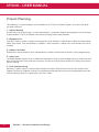
Project Planning
System Design Guidelines
Compatible Equipment
Detectors
Callpoints
Beacons and Sounders
Base Sounder
Stand Alone Sounders
Loop Powered Beacon
Compatible Interfaces
3 Channel I/O
1 Channel I/O
Zone Monitor Unit
Shop Monitor Unit
Spur Isolator
4 Way Sounder Circuit Controller
Micro Interfaces
Fan Controller Interfaces (FC18 / FC6)
Equipment Compatiblity
System Overview
Technical Specification
Optional Functions as per EN54 Pt 2 & 4
Optional Functions Not Approved to EN54 Pt 2 & 4
Cable and Wiring
Installation
Fixing Details
External Connections
Networking
Inputs/Outputs
Maintainance
5
6
7
8
9
10
11
11
12
12
13
13
14
14
15
16
16
17
18
19
20
22
24
28
29
30
31
32
33
34
36
Section 2 - Panel Assembly Information
Attaching Panel Door
Installing Optional Screen Door
Replacing Printer Paper Roll
38
39
40
Section 3 - Commissioning
Commissioning Mode
Configuration
Panel Fault Finding
Protocol
PC Comissioning Software
42
43
44
45
46
Section 4 - Panel Controls And Indicators
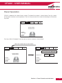
System Indicators
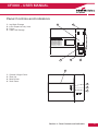
Panel Layout
Touch Screen Display
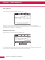
Panel Operation
Public (Access Level 1)
Evacuate (Access Level 2)
Silence Alarms
Mute Buzzer
Reset
Pre Alarms
Disabled Devices
50
51
52
53
54
55
56
57
57
58
58
View Faults
Enable / Disable (Others Menu)
Print
Lamp Test
Weekly Test
View Events
Check Auto Config
Replace Device
Test Device
Test Zone
Sounder Level Test Mode
Global LED Flashing On/Off
One Man Walk Test
Load CDR From Laptop
Download CDR To Laptop
Auto Learn
Erase Log
System Details
Analogue Levels
Printer Settings
Change Panel Number
Number of Panels In Network
Screen Cover
Programming I/O and Sounders
Sound Settings
Change Date/Time
Change Address Text
Change Zone Text
Change Panel Text
Configure Zones
Change User Code
Add Zone
Delete Zone
Add Device
Delete Device
Configure Heat Detectors
Network
Password Protection
59
59
61
62
63
64
65
66
67
68
69
70
71
72
73
74
75
76
77
78
79
80
81
82
83
84
85
86
87
88
89
90
91
92
93
94
95
96
Section 5 - Appendix
Spur Isolator
4 Way Sounder Controller
Zone Monitor Unit
Shop Monitor Unit
1 Way Input Output Unit
Detector Base Wiring
System Wiring
IP66 Wall Sounder
Internal Wall Sounder
Base Sounder
3 Way Input Output Unit
Loop Powered Beacon
Callpoint
EN54 Product Spec Label
Battery Disposal Instructions
CE Marking
98
99
100
101
102
103
104
105
106
107
108
109
110
111
112
113
3
CF3000 - USER MANUAL
Section 1
System Installation and Design
4
Section 1 - System Installation and Design
CF3000 - USER MANUAL
Introduction
CF3000 provides all of the sophisticated features required of a leading edge analogue addressable fire
system along with the simple operation and neat installation demanded by installers and building users.
The panel can be flush or surface mounted and the generously sized metal back box allows ample
facilities for rear or top cable entries. It is available in single two and four loop versions, with or without an
integral printer.
In addition both passive and fully functional repeater panels are available.
A comprehensive range of ancillary devices is available to operate with CF3000, including optical,
ionisation, photo-thermal and heat detectors, base mounted and stand alone sounders (including an IP67
version) a loop powered beacon and a wide range of input and output interfaces.
Each of the CF3000 system components has been specifically designed to operate as part of a CF3000
system, this provides an assurance that the panel, the detectors, the interfaces and the ancillaries are all
fully compatible with each other and that the full range of system functionality is supported by each
device.
Each loop of a CF3000 panel can accommodate up to 200 addresses. To comply with EN54
requirements no more than 512 addresses should be connected to a single panel. Each panel can
indicate upto 96 zones. Panels are available with upto 4 detection loops, up to 126 panels can be
networked together to form a single system capable of operating with over 32,000 devices.
Note:
Network systems fall outside the scope of EN54.
Section 1 - System Installation and Design
5
CF3000 - USER MANUAL
Project Planning
The following is a typical program and timetable for a CF3000 installation project, once the initial order
has been received:
1. Project Meeting
Installer and user to be present; system specifications, schematic diagram and proposed circuit drawing
to be available. CF3000 Installation and Commissioning Guide to be provided.
2. Equipment Fix
Typically 2 week's notice is required for equipment to be delivered. Cable to be installed and bases/back
boxes to be fitted. Then fire detectors, callpoints, alarm sounders, isolator units and interface units to be
installed.
3. Address Schedule
Schedule of sensor locations to be completed by installer and returned to enable system programming.
4. Auto Learn
Fire panel/repeater panels to be installed and terminated. System to be powered up by installer and auto
learn mode activated (see Auto Learn section). System to be tested and verified by installer, prior to final
commissioning.
5. Final Commissioning
Minimum 2 weeks notice is required from receipt of Address Schedule and Commission request form.
Cooper Fire Service Engineer to attend site implement/oversee the final commissioning procedures (see
Commissioning section), in conjunction with the installer.
6
Section 1 - System Installation and Design
CF3000 - USER MANUAL
System Design Guidelines
Guidelines
Systems should to the relevant local standards and codes of practice, for the UK this is BS5839 Pt 1.
CF3000 meets all the relevant requirements of BS5839 Pt 1: 2002. Installation planning is simplified by
the fact that every addressable CF3000 device contains an integral short circuit isolator. Care must be
taken to ensure that local standards requirements regarding aspects such as loop coverage, area
covered by a single spur and cable specification are observed.
There may be certain applications in which deviations from the code may be necessary and these must
be listed on the commissioning certificate. (See commissioning section).
Loop Lengths
The maximum permitted loop length is 2 km measured from the near to the far terminals on the CF3000
motherboard PCB. There is no minimum limit to loop length. Any wiring spurs off the loop must be
included within the 2 km limit. On long loop runs, the lengths of wiring rises and falls (between floors,
down to manual callpoints) must be included. Remember to include these especially when taking loop
lengths from plan drawings.
Loop Loading - Total Number of Addresses
The total number of addresses per loop is 200. this includes detectors, callpoints and all other
addressable items (e.g. MPU, MIO, loop repeaters etc.) When designing systems its recommended that
allowances are made for future expansion, Short circuit isolators are incorporated into every CF3000 loop
device, including Smoke detectors, heat detectors, sounders, callpoints and interfaces. Therefore, no
further fault protection is required, in the event of a single fault, none of the devices connected to the loop
will fail to operate as the fault will be isolated by the two adjacent devices. Spur connected devices
downstream of a cable fault will cease to function.
CF3000/PR Repeater Panels
Each repeater unit requires one address and consumes no more current from the loop than a smoke
detector. The repeater also requires a local mains supply and incorporates battery backup.
Loop Loading System Verification
Unless a loop loading calculation has already been carried out, please contact our technical support
department (01302 303350), before starting installation to verify that a proposed loop loading
arrangement is acceptable.
Section 1 - System Installation and Design
7
CF3000 - USER MANUAL
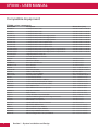
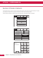
Compatible Equipment
CF3000 system components
Order Code
CF3000/1
CF3000/2
CF3000/4
CF3000/1/P
CF3000/2/P
CF3000/4/P
CF3000/1/G
CF3000/2/G
CF3000/4/G
CF3000/1/P/G
CF3000/2/P/G
CF3000/4/P/G
CF3000/COV
CF3000/PR
CAS380
MASC
CASBB384
MASB870-NT
CAS381
CAS381WP
CAS382
CBG370S
CBG370WP
CIO351
CIO351T
CIO351S
CMIO353
CZMU352
MIU87-IS
CSUM355
CSI350
CSC354
CAB300
CAP320
CAH330
CAPT340
MIU872
MCIM-C
MCOM-S
MCOM-R
MICM-NF
8
Description
1 Loop CF3000 Panel
2 Loop CF3000 Panel
4 Loop CF3000 Panel
1 Loop CF3000 panel c/w integral printer
2 Loop CF3000 panel c/w integral printer
4 Loop CF3000 panel c/w integral printer
1 Loop CF3000 Panel Graphite finish
2 Loop CF3000 Panel Graphite finish
4 Loop CF3000 Panel Graphite finish
1 Loop CF3000 panel c/w integral printer Graphite finish
2 Loop CF3000 panel c/w integral printer Graphite finish
4 Loop CF3000 panel c/w integral printer Graphite finish
Hinged protective cover kit
Passive repeater for CF3000
Sounder Base
Cover for CAS380
Base Sounder Beacon
Base Beacon
Wall Sounder
IP66 Wall sounder
Addressable Beacon
Surface / Flush Callpoint
Weatherproof Callpoint
3 Channel I/O Device
3 Channel I/O Device 1 Address
3 Channel I/O Device reset on silence
1 Channel Output Unit (mains rated)
Zone Monitor Unit
Zone Monitor Unit Intrinsically Safe
Shop Unit Interface
Spur Isolator
4 Way Sounder Circuit Controller.
Common Mounting Base For Analogue Detectors
Optical Smoke Detector
Multi Mode Heat Detector
Combined Photo Thermal Detector
Micro Zone Monitor Unit
Micro Callpoint Input Module
Micro Sounder Output Module
Micro Output Module Resetable
Micro Analogue Non Fire Input Module
Section 1 - System Installation and Design
Dimensions (mm)
495 W x 400 H x 180 D
495 W x 400 H x 180 D
495 W x 400 H x 180 D
495 W x 400 H x 180 D
495 W x 400 H x 180 D
495 W x 400 H x 180 D
495 W x 400 H x 180 D
495 W x 400 H x 180 D
495 W x 400 H x 180 D
495 W x 400 H x 180 D
495 W x 400 H x 180 D
495 W x 400 H x 180 D
102 Dia x 40 D
102 Dia x 13 D
114 Dia x 36 D
114 Dia x 36 D
105 L x 105 H x 95 D
108 L x 108 H x 103 D
95 Dia x 50 D
85 L x 85 W x 53 D
108 L x 108 W x 65 D
147 L x 88 W x 57 D
147 L x 88 W x 57 D
147 L x 88 W x 57 D
180 L x 130 H x 60 D
150 L x 89 H x 58 D
150 L x 89 H x 58 D
150 L x 89 H x 58 D
112 L x 41 H x 33 D
300 L x 300 H x 74 D
104 Dia x 22 D
101 Dia x 33 D
101 Dia x 43 D
101 Dia x 43 D
63 L x 35 H x 18.5 D
63 L x 35 H x 18.5 D
63 L x 35 H x 18.5 D
63 L x 35 H x 18.5 D
63 L x 35 H x 18.5 D
CF3000 - USER MANUAL
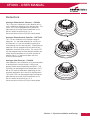
Detectors
Analogue Photoelectric Detector - CAP320
This is the most commonly used detector and is
most suitable for detecting slow burning fires. The
status LED can be programmed to either be
permanently off under normal conditions or to
pulse in order to confirm that it is in
communication with the CF3000 control panel.
Analogue Photo/thermal Detector - CAPT340
This is a new addition to the Cooper range of
detectors. It is the ideal detector for a multi-use
environment as it has an excellent response to
smouldering and fast burning fires. Photo/thermal
detectors can be programmed for thermal only
operation at certain times of day. The status LED
can be programmed to either be permanently off
under normal conditions or to pulse in order to
confirm that it is in communication with the
CF3000 control panel.
Analogue Heat Detector - CAH330
Heat detectors are suitable for dusty environments
or environments where smoke is likely to be
present under normal operating conditions. The
CAH330 can be programmed to operate in A1R,
BS or CS mode of operation depending on the
required application and sensitivity requirements.
The status LED can be programmed to either be
permanently off under normal conditions or to
pulse in order to confirm that it is in
communication with the CF3000 control panel.
Section 1 - System Installation and Design
9
CF3000 - USER MANUAL
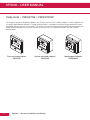
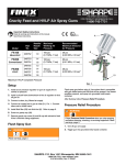
Callpoints - CBG370S / CBG370WP
The range of purpose designed callpoints for CF3000 consists of a surface callpoint, a flush callpoint and
a surface weatherproof callpoint. A range of accessories is available including a hinged protective cover,
resettable element kit and a flush bezel. The status LED can be programmed to either be permanently off
under normal conditions or to pulse in order to confirm that it is in communication with the CF3000
control panel.
Flush mounted callpoint
CBG370S
10
Surface mounted callpoint
CBG370S
Section 1 - System Installation and Design
Weatherpoof callpoint
CBG370WP
CF3000 - USER MANUAL
Sounders and Beacons
A wide range of loop powered sounders and beacons are available to operate with CF3000 consisting of
a combined sounder base with a maximum output of 95 dB(A), a standalone sounder with a maximum
output of 100 dB(A) that is available in standard or weatherproof versions and a stand alone loop
powered beacon.
For applications where a discreet dedicated sounder is required, a cover plate is available for the white
base mounted sounder enabling it to be used as a stand alone wall or ceiling mounted sounder.
All of these devices are fully programmable via the sophisticated CF3000 multi stage cause and effect
programming facilities.
All sounders have multiple selectable volume settings, the volume setting is controlled globally
by the CF3000 panel and so can be altered without needing to access the sounder. Alternatively
individual sounders can be set through the Cooper programming utility.
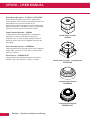
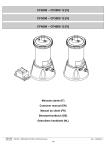
Base Sounder - FXN538LBS
The CAS380 has been designed specifically to complement the latest generation of Cooper soft
addressed detectors. it consists of a first fix bracket, and a main body which clips onto the bracket
incorporating the sounder and a detector mounting base in a single composite assembly.
Base sounder
CAS380
Base sounder with detector fitted
CAS380
Base sounder with MASC fitted
CAS380
After the body has been clicked into place and connected, a detector or front cover is then added to
complete a very simple quick and neat installation. The cover enables the CAS380 to be used as a
discreet stand alone wall or ceiling mounted device. The sounder base design incorporates a mechanism
that can be activated if required to lock either the detector or the cover into place to prevent unauthorised
removal.
Section 1 - System Installation and Design
11
CF3000 - USER MANUAL
Stand Alone Sounders - CAS381 / CAS381WP
Stand alone sounders are ideal for applications
where greater sound outputs are required than can
be achieved with a base sounder or for
applications requiring a higher level of resilience or
ingress protection. 2 different versions are available
standard version and an IP66 rated version.
Loop Powered Beacon - CAS382
A loop powered flashing beacon is available for
applications where visual alarm indication is
required such as areas of high ambient noise or
buildings which are used by people who are hard
of hearing.
Stand alone sounder
CAS381
Base Sounder Beacon - CASBB384
Loop powered base sounder with a built in beacon
where both sound and visual alarms are required.
Taking 1 address
Base Beacon - MASB870-NT
Loop powered base beacon where visual alarm
without sound are required. Taking 1 address.
Stand alone sounder - weatherproof
CAS381WP
Loop powered beacon
CASBB384
Loop powered beacon
MASB870-NT
12
Section 1 - System Installation and Design
CF3000 - USER MANUAL
Compatible Interfaces
CF3000 has been designed to be suitable for a wide range of applications, various interfaces have been
developed to enable the simple integration of other fire systems or building control and safety systems.
The following devices are available:
3 Channel I/O device - CIO351
CIO351 has 3 input channels and 3 output channels, it is used to monitor up to three separate inputs
from equipment such as sprinkler flow switches and also to provide 3 separately controlled volt free
output contacts which are intended to be used to control external equipment such as air handling plant
or access control systems. All inputs and outputs operate completely independently of each other and
can be programmed using the sophisticated cause and effect capabilities of CF3000 to operate either
globally or in response to activation of specific devices or specific inputs. Inputs are monitored for open
and short circuits, a specific resistance is required to activate an alarm condition, fully open or short circuit
conditions are monitored and generate a system fault signal. Inputs are suitable for use as fire signal
inputs such as from a sprinkler flow switch, however they can also be used to monitor non fire inputs
such as external keyswitches. Outputs are rated to switch a maximum of 1A resistive at 30V dc.
CIO351fixes to a standard, deep, double gang back box and can be either surface or semi recess
mounted.
CIO351T
This unit is identical in build to the CIO351 but this has been designed to take 3 addresses (this can be
expensive in terms of outputs because it replies as 3 x 3 Channel I/O's), this means that text information
can be allocated to each channel. It also allows each individual input and output to be disabled (by
address). The maximum number of addressable CIO351T per loop is 6.
CIO351S
Once again this unit is identical with the CIO351 only taking 1 address. The programming is the same as
the CIO351. This unit was designed so that the relay outputs reset on silence rather than full reset, thus
enabling the user to interface this device with other fire panels and hence prevents locking up. The
maximum number of addressable CIO351S per loop is 20.
3 channel I/O device
CIO351 / CIO351T/ CIO351S
Section 1 - System Installation and Design
13
CF3000 - USER MANUAL
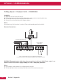
1 Channel I/O device with mains rated switching capability - CMIO353
CMIO353 is a single channel input / output unit, the output is capable of switching up to 8 A at 230 V ac.
Commonly used for applications such as door release controls and plant shut down signalling The input
is monitored for open and short circuits, a specific resistance is required to activate an alarm condition,
fully open or short circuit conditions are monitored and generate a system fault signal. The input is
suitable for use as a fire signal input such as from a sprinkler flow switch, however it can also be used to
monitor non fire inputs such as an external keyswitch.
1 channel I/O device
CMIO353
Zone monitor unit - CZMU352
CZMU352 is designed to enable a zone of compatible conventional detectors and callpoints to be
connected into the CF3000 loop, it is compatible with up to 20 Cooper conventional detectors connected
via FXN520 bases. Please refer to local standards e.g. BS5839 Pt1:2002 for details of the maximum
allowable area to be covered by a single spur / zone. CZMU352 fixes to a standard, deep, double gang
back box and can be either surface or semi recess mounted. When semi recessed only the front section
protrudes giving a maximum 29mm depth.
MIU871-IS
Similar to the above but the detection zone has been programmed to accept a Zener barrier and zone of
intrinsically safe detectors. End of line for this zone now becomes 6k8 and the diode in the detector base
must be removed.
Zone monitor unit
CZMU352 / MIU871-IS
14
Section 1 - System Installation and Design
CF3000 - USER MANUAL
Shop Unit Interface - CSUM355
CSUM355 accepts a zone of conventional detectors plus an unlimited number of callpoints which can be
connected to the same input as the detectors or a separate callpoint input if required. There is also a
facility to connect a power supply, which can then be monitored for fault.
In addition it has the facility to connect two circuits of conventional polarised sounders, which are
monitored by means of an end of line resistor and powered in alarm conditions from the external power
supply. The sounder circuits can be programmed to operate in pulsed, continuous or time delayed mode.
Please refer to local standards e.g. BS5839 Pt 1:2002 for details of the maximum allowable area to be
covered by a single spur / zone.
Note: This unit must always be used with a 24 V power suply
Shop unit Interface
CSUM355
Section 1 - System Installation and Design
15
CF3000 - USER MANUAL
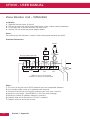
Spur Isolator - CSI350
Enables soft addressing to work when the loop contains spurs, it controls the addressing operation so
that when the system reaches a spur, all devices on the spur are allocated an address before it continues
addressing the loop. The device also incorporates a short circuit isolator. Because each device contains a
short circuit isolator only 1 is required at the start of each spur. CSI350 is mounted on a standard deep
double gang back box (supplied) please refer to BS5839 Pt 1:2002 f
Spur Isolator
CSI350
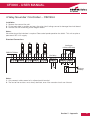
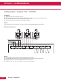
4 Way Sounder Circuit Controller - CSC354
CSC354 provides power for 4 separately controllable conventional sounder circuits, each circuit can be
separately programmed. CSC354 is designed to greatly simplify installation in applications where
specialist sounders or beacons are required since it powers the sounders and allows full control of the
sounder operation without having to wire the sounder back to the CF3000 control panel.
A 4 way unit takes up a single address but each circuit can be independently controlled. An CSC354 unit
requires a local un-switched 230 V supply and incorporates a back up battery to 24 hours of standby
operation followed by a minimum of 30 minutes of full alarm ringing. A standby of 72 hours can be
achieved at the expense of reduced load capability.
4 Way sounder circuit controller
CSC354
16
Section 1 - System Installation and Design
CF3000 - USER MANUAL
Micro Interfaces
A range of micro interfaces modules are also available:
MCIM
Is a competitively priced input module, designed to enable a Cooper panel to accept input signals from
external devices such as key switches and sprinkler flow switches. It is extremely compact and therefore
ideal for incorporation into other equipment. The maximum number of addressable MCIM per loop is 20.
MCOM
Is a competitively priced output module, designed to enable a Cooper panel control external devices such
as door holders or access control systems. It is extremely compact and therefore ideal for incorporation
into other equipment. The maximum number of addressable MCOM per loop is 20.
MIU872
Is a compact single zone input, soft addressed, microinterface, incorporating integral short circuit isolators.
It is fully compatible with the current range of Cooper analogue fire detection panels. It is suitable for
interfacing a zone of up to 20 conventional Cooper detectors onto a Cooper analogue fire panel. It will
operate with any Cooper conventional detector in configuration with a schottky diode type base.
MCIM-C (Identified as a Callpoint)
Is a compact input module used to accept input signals from external equipment such as beam detectors,
flow switches, valve monitor switches etc. The maximum number of sounder devices per loop is 200.
MCOM-S (Identified as a Sounder)
Is a compact single channel output unit. This device is identified as a sounder output by a Cooper
addressable panel. The maximum number of sounder devices per loop is 60.
MCOM-R
Is a compact output module used to control or signal external equipment which require removal of power
for reset purposes. The maximum number of addressable MCOM-R per loop is 20.
MICM-NF
Is a compact single channel input unit. This device is identified as a non-fire input module by the Cooper
addressable panel. The maximum number of addressable MICM-NF per loop is 200. Complex cause and
effect can still be achieved using the latest site installer software without any indication on the panel.
However the action will still be seen in the event log. Ideally suited for non fire applications.
Micro interfaces
MCIM / MCOM / MIU872 / MCIM-C / MCOM-S / MCOM-R / MICM-NF
Section 1 - System Installation and Design
17
CF3000 - USER MANUAL
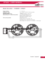
Fan Controller Interfaces (FC18 / FC6)
FC18 and FC6 Interface is designed to work with the Cooper range of analogue fire alarm control panels,
providing the capability to control and display the status of AHU fans.
FC18 and FC6 Interface is connected to a Cooper analogue addressable fire alarm control panel by
means of the comms loop, utilizing only one address whilst providing the ability to monitor and control up
to six AHU Fans.
Each FC6 and FC18 Interface incorporates its own CPU specifically configured to control the relevant
input and output logic making programming quick and easy via the ‘CAPPER’ software or site installer.
Using the CAPPER software or site installer, each individual Fan Control channel on the FC6 is
programmed to an output and feedback input field device to control and monitor the status of an AHU
fan.
Features
> Convenient loop mounting
> Comprehensive LED display
> Surface/rack mounting options
> Key operated auto/manual operation
> Comprehensive software cause and effect
Fan controller interface
FC6
18
Fan controller interface
FC18
Section 1 - System Installation and Design
CF3000 - USER MANUAL
Equipment Compatibility
Detectors
Loop wired detectors must be of the Cooper series soft addressed analogue type. FXN500 series
conventional detectors can be connected via an CZMU352 interface. The connection of other detector
types via an CZMU352 interface is not recommended.
Callpoints
Loop wired callpoints must be the Cooper series soft addressed analogue type, FX200 series
conventional callpoints can be connected via an CZMU352 interface. The connection of other callpoint
types via an CZMU352 interface is not recommended.
Sounders
Loop powered addressable sounders must be of the Cooper series soft addressed analogue type.
Conventional sounders can also be connected either to the conventional sounder circuits at the panel or
to the loop via a CSC354 addressable sounder controller interface providing they meet the following:
1. They are suitable for operation between 18 V and 28 V.
2. They are polarised and suppressed.
3. The total alarm load is less than the rating of the panel / alarm power interface.
Note:
It is possible to use devices outside these requirements if they are supplied with power from a separate
source and switched via a suitable relay.
Relay Circuits
Additional relays can be added to the CF3000 system by using either CMIO353 or CIO351 relay units.
Relays / Auto-dialers and auxiliary equipment A wide variety of relays and other equipment can be
connected to the CF3000 system, but you should note the following constraints:
1. CF3000 provides monitored outputs to drive fire and fault relays mounted in external equipment.
External relays should be suppressed. If a non-suppressed relay is used then a diode can be
connected to suppress any reverse EMF on the release of the relay which might cause the panel to
malfunction.
2. A 24 V dc output is provided at the panel to make it easy to connect ancillary equipment. Although the
panel can supply a continuous quiescent load of up to 30 mA, BS5839 precludes this practice and
any ancillary equipment you connect should only consume power in the alarm or fault mode to meet
the requirements of BS5839.
Additional Instructions for Electromagnetic Compatibility
When used as intended this product complies with EMC Directive (89/336/EEC) and the UK EMC
regulations 1992 (SI 2372/1992) by meeting the limits set by the standards BS5406 (Pt 2 & 3) 1988,
EN50130-4 immunity and EN 61000-6-3 emission requirements. The following installation guidelines
must be followed.
1. External cables must be connected using the cable entries or knockouts provided.
2. When routing external cables inside the product they must be
a) Kept as short as possible
b) Routed close to the housing
c) Kept as far as possible from the electronics
Any modifications other than those stated in this manual, or any other use of this product may cause
interference and it is the responsibility of the user to comply with the EMC and Low Voltage Directives.
Section 1 - System Installation and Design
19
CF3000 - USER MANUAL
System Overview
Simple User Interface
The main element of the user interface with CF3000 is a large (120mm x 90mm visible area) touch screen
display, which provides comprehensive user information and also acts as a multifunctional keypad.
Comprehensive context sensitive help information is provided throughout the menus to assist unfamiliar
users with system operation.
The CF3000 touch screen display automatically reconfigures to suit the selected function, for example, if
the change device text menu option is selected, the touch screen is automatically formatted as a full
QWERTY keyboard to enable fast and simple text entry.
The use of the touch screen display enables a wide range of user and engineering facilities to be
incorporated into the panel whilst still offering simple operation.
As well as a large format LCD display providing full system status information, the panel incorporates 96
traditional zone indication LED's to provide clear information about the status and spread of a fire even to
a user who is completely unfamiliar with the operation of the system.
In addition there are a number of system status LED's designed to give clear status information to non
technical users.
User Configuration And Maintenance Facilities
CF3000 has comprehensive facilities for on site system configuration, whereby the user can add or
remove simple devices or change device text directly via the panel, without the need for a service
engineer to visit site. For initial configuration or major system changes special PC configuration software
is available enabling Cooper Lighting and Safety personnel to do this more efficiently than can be
achieved using the system screen. Exiting configurations can be uploaded to the PC so that changes can
be made to the existing system rather than having to revert to initial files.
Sophisticated Sounder Control Facilities
CF3000 has the ability to support highly complex ringing pattern requirements. Multistage cause and
effect programming is possible whereby each addressable sounder or output interface can be
programmed independently if required and can be set to respond to specific addresses, specific
detection zones, specific panels on a networked system or standard global ringing.
The panel supports three separate sets of programming per sounder and each stage can be triggered
differently For example, if a single detector is triggered the panel can be programmed such that the
sounder nearest to the detector operates immediately and continuously, the remaining sounders in the
affected zone operate in pulsed mode and the other sounders delay for a selectable period to allow the
cause of the alarm to be investigated before global ringing commences.
20
Section 1 - System Installation and Design
CF3000 - USER MANUAL
Spur Tolerant Soft Addressing
CF3000 utilises intelligent soft addressing technology to greatly simplify the installation and
commissioning processes. Once the system has been installed and the autolearn menu selected, the
CF3000 control panel will automatically scan the detection loops and allocate each device with an
address number corresponding with its position on the loop, this avoids the traditional need for manual
addressing of the system devices which is time consuming and provides a potential for error.
A major innovation with CF3000 is the ability to incorporate spurs of analogue devices which are fed from
the main loop by utilising a spur isolator. Whenever the panel detects a spur, it breaks from allocating
address numbers to the loop wired devices, allocates address numbers to each of the devices on the
spur in sequence and then continues to address the devices on the main loop. Every CF3000 analogue
device incorporates an integral short circuit isolator ensuring maximum system integrity. A single short
circuit will not disable any loop-mounted devices, the isolators in the devices each side of the short circuit
will operate and the CF3000 control panel will drive communication from both ends of the loop. The spur
isolator also incorporates a short circuit isolator such that in the event of a short circuit on the spur, the
integrity of the main loop will not be compromised. Please refer to local standards e.g. BS5839 Pt 1:2002
for details of the maximum allowable are to be covered by a single spur.
Simple Future Expansion
CF3000 is designed to ensure simplicity of future expansion. If an additional device is added after the
system has been programmed, the CF3000 will allocate the next available address, it will not alter any of
the existing address numbers allocation thus enabling simple updating of as fitted drawings etc. Similarly
if a device is removed, the relevant address is saved as a spare address for future use, the addresses of
the remaining devices are not altered.
Integral Power Supply and Battery
The CF3000 panel is designed for ease of installation, the power supply and battery are integral to the
main control panel so only a single panel is required even on large 4 loop systems.
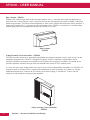
Optional Printer
CF3000 panels are available with optional built in printers. Where a printer is fitted, it is housed behind a
printer cover door, which can be opened by means of a special tool (Supplied) to provide simple and safe
access to the printer paper roll without exposure to any live equipment. Paper replacement is extremely
simple due to the drop in loading method and auto feed printer design, the paper roll is simply dropped
into the purpose designed cradle and the end of the roll is then offered up to the printer, which will then
automatically load the paper ready for use. The printer can be set to either print automatically or to print
on demand When a printer is not fitted, a removable, flush fitting blanking plate is used to cover the
printer paper aperture to enhance the appearance of CF3000 and to preserve its ingress protection
rating.
Optional Hinged Lockable Cover
With a standard panel, access to all panel functions is controlled by a series of pass codes, which are
entered via the touch screen display, for maximum security, a facility is built into the CF3000 to enable the
user to alter the user pass code as required. For applications where a high level of resilience is required, a
clear hinged lockable front cover is available which allows the screen and all of the system status
indicators to be clearly seen but prevents access without first unlocking the cover. A single concealed
locking mechanism provides access to both the printer door and the optional display cover Where a
hinged cover is fitted, additional buttons are provided to scroll the display and to silence the fault buzzer
without opening the lockable cover
Section 1 - System Installation and Design
21
CF3000 - USER MANUAL
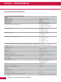
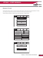
Technical Specification
Power Supply (Approved EN54 pt 4)
Mains
Nominal voltage
Nominal current
Maximum current
Input fuse R1
Output Voltage including tolerances
230 Vac + 10%, -15%
75 mA
750 mA
NTC SG39 Imax 4Amp
26 V = 18.5 to 29.5 V
26 V RAW = 18.5 V to 29.5 V
5 V Output = 4.6 V to 5.5 V
Ripple voltages
26 V = 800 mV
26 V RAW = 800 mV
5 V Output = 430 mV
Maximum loadings
26 V O/P = 0.98 A
26 V RAW O/P = 1.7 A
5 V = 0.5 A
Standby current (4 loops loaded)
26 V = 280 mA
26 V RAW = 150 mA
26 V = 280mA
26 V RAW = 150 mA
5 V = 43 mA
CF3000 is protected by an internal thermal device, this requires no maintenance
* I max a, I max b and I min = Current as specified in BSEN54-4 Published 2006 (Amendments 1 and 2)
Batteries
Number of batteries
2
Manufacturer
YUASA NP12-12
Capacity
12 Ah
Battery fuse
6.3A Anti-Surge (F4)
Maximum battery current
3.5 Amps
Standby current (mA)
175 (4 loops), 125 (2 loops)
Maximum charging current to the batteries
1.0 Amp
Float voltage
27.4 V
Final voltage
21.0 V
Charging characteristics
Constant voltage with 0.970 A
limit with temperature
compensation
Maximum current drawn from the batteries (when the mains is not available) 3.5 Amps
Deep discharge protection
20.6 V
Battery Internal Impedance fault
>0.5 ohms
Inputs
Addressable loops
Max number
1-4
Max loop load per loop
220 mA
Max number of addressable devices per loop
200
Class change
Operated by external volt free contact
22
Section 1 - System Installation and Design
CF3000 - USER MANUAL
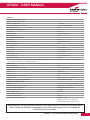
Outputs
Conventional sounder circuits
Number of sounder circuits
4
Total sounder load
1.5 Amps
Sounder circuit fuses (F1/2/3/4)
1.6 Amp (Quick Blow)
End of line resistor
6k8
Fire Protecting Equipment
Max load
60 ma
Fused (PTC3)
100mA polyswitch
End of line resistor
6k8
Fault Routing Equipment
Max load
30 ma
Fused (PTC1)
100mA polyswitch
End of line resistor
6k8
Auxiliary Relays - The auxiliary relays provide fused volt free change over contacts. These contacts are not monitored.
Max load
24 V 1 Amp
Fuse (PTC4)
1.35 Amps polyswitch
Auxiliary
24 V Supply
Nominal voltage
24 V ±10%
Fuse (PTC5)
100 mA Polyswitch
Maximum current
30 mA
This output is not to be used for fire protecting equipment or fire alarm routing equipment any power taken from the
alarm system will effect the standby duration
RS485 Port - Serial output port for driving CF3000 repeater panels, mimics etc. This output is short circuit protected
Max cable length
2km
Min recommended cable size
1mm² (Screened)
RS232 Port - Serial output port for driving CF3000 repeater panels, mimic etc. This output is short circuit protected
Printer
(Optional)
Type
High speed thermal
Number of characters per Line
40
Type of paper
58mm x 46mm Thermal Roll
Replacement paper roll order code
ADF6PRINTERPAPER
Mechanical Specification
Weight
incl batteries 18kg, excl batteries 9kg
Dimensions (Standard batteries)
495mm(L) x 395mm(H) x 180mm(D)
Type of material (backbox)
Mild Steel (power coated)
Type of material (Facia)
PC/ABS
Flammability rating
UL 94 V0
Total number of knockouts
51
Diameter of knockout
20mm
Anti-Tamper cover (optional)
Weight : 250g
Material used : Poly Carbonate
Flammability rating : UL 94 5VA
Terminal Blocks: Do not use excessive force when tightening the screws on the terminal block
Risk of explosion if battery is replaced by an incorrect type dispose of the used batteries
according to the instructions
Section 1 - System Installation and Design
23
CF3000 - USER MANUAL
Optional Functions as per EN54 Pt 2 & 4
CF3000 is approved to EN54 Parts 2 & 4 including all the following options which can be selected as
required
Panel Outputs
Panel Sounders: (option 7.8 EN54 Pt 2)
2 pairs of outputs are provided. ONLY polarised equipment should be used. Ensure the polarity of the
connections are observed at all times and end of line resistors (6k8 5%) are fitted for correct operation.
The total alarm load across all sounder outputs = 1.5 Amp All outputs are fused with 1.6 Amp glass fuse
alarm devices should be spread equally across the 4 sounder circuits.
WARNING: Do not exceed the rated output current
Output Fire Alarm Routing Equipment (option 7.9 EN54 Pt 2)
This output, which is fused, and monitored using a 6.8k end of line resistor, is used for the automatic
transmission of the fire signals to fire alarm routing equipment (e.g. fire brigade). It operates by providing
24V output to an auxiliary device (e.g. relay). It is current limited to 30 mA using a resettable polyswitch.
Class change and test conditions do not operate this output. If operated under a fire alarm condition, the
indication will be displayed on the Touch screen display and will remain until the fire alarm is reset. Ensure
the polarity of the connections are observed at all times and end of line resistors (6k8 5%)
are fitted for correct operation.
Output to Fire Alarm Protecting Equipment (option 7.10 EN54 Pt 2)
This output, which is fused, and monitored using a 6.8k end of line resisters used for the transmission of
the fire signals to controls for automatic fire protecting equipment (e.g. Door released units etc).It operates
by providing 24 V output to an auxiliary device (e.g. relay). It is current limited to 30 mA using a resettable.
polyswitch. Class change and test conditions do not operate this output. If operated under a fire alarm
condition, this output remains energised until the fire alarm is reset. Ensure the polarity of the connections
is observed at all times and end of line resistors (6k8 5%) are fitted for correct operation.
Output to Fault Warning Routing Equipment (option 9.4.1c EN54 Pt 2)
This output, which is fused and monitored using 6.8k end of line resistor, is used for the
transmission of fault signals to fault warning routing equipment This output is monitored using 6k8
end of line resistor and it current limited to 30 mA.Under normal condition it operates by providing
12 V dc which can be connected directly to a 12 V auxiliary device(relay).It is current limited to 30 mA.
Under fault conditions or even if the CF3000 is powered down, this output will be switch to O V.
Ensure the polarity of the connections is observed at all times and end of line resistors (6k8 5%)
are fitted for correct operation.
Delays to Outputs (option 7.11 Of EN54 Pt 2)
The CF3000 has the option to delay the operation of panel sounders, the fire routing equipment output
and the fire protecting equipment. This delay is selectable using the CF3000 site installer download
software .The delay is configurable in increments of 1 minute up to a maximum of 10 minutes.
This delay can be enabled and disabled at access level 2. The CF3000 has the facility for a specific
callpoint to override this delay by programming this callpoint via an input interface to provide an evacuate
signal using CF3000 site Installer.
24
Section 1 - System Installation and Design
CF3000 - USER MANUAL
Dependencies on More Than One Alarm Signal - Type C (option 7.12.3 Of EN54 Pt 2)
The CF3000 has the facility to inhibit the operation of the output sounders, output to fire routing
equipment and the output of the fire protecting equipment until one more confirmatory signals are
received from different zones. This feature is programmable using CF3000 Site Installer Software.
Alarm Counter (option 7.13 EN54 Pt 2)
The panel records the number of instances that it enters the fire alarm condition. This is abbreviated in the
touch screen by "AC" and it is displayed in the fire window at access level 2. This counter can only be
reset by the manufacturer.
Optional Auxiliary Board Vds Requirement (Option Not Required by EN54)
This board can be connected to an Extinguishing system as well as a Fire Brigade Control Panel.
This board has been tested and approved in according with DIN14661 and DIN 14675.
Input / Outputs to Fire Brigade Panel
Outputs
Output 1:
Output 2:
Output 3:
Fire Protecting Equipment Operated "Extinguishing On"
This output is ON in alarm condition to indicate that the CF3000 control and indicating
equipment has operated the fire protecting equipment (option 7.10 of EN54 pt2 )
Fire Routing Equipment Operated "Fire Brigade Link"
This output is ON in alarm condition to indicate that the CF3000 control and indicating
equipment has operated the fire routing equipment (option 7.9 of EN54 pt2 ).
Disablement of Fire Protecting Equipment
This output is ON to indicate that the fire protecting equipment has been disabled either by
the CF3000 control and indicating equipment or the fire brigade panel.
Section 1 - System Installation and Design
25
CF3000 - USER MANUAL
Output 4:
Output 5:
Output 6:
Disablement of the Fire Routing Equipment
This output is ON to indicator that the fire routing equipment has been disabled either by the
CF3000 Control and indicating equipment or the fire brigade panel.
Reset from Fire Alarm Condition
This output is ON to indicate that the CF3000 control and indicating equipment is in alarm
condition. This output will remain on for at least 15mins after reset or when the reset has
been activated from the fire alarm brigade panel
Disablement of Sounders
This output is ON to indicate that the sounders have been disabled either by the CF3000
control and indicating equipment or the fire brigade panel
Inputs
Input 1:
Input 2:
Input 3:
Input 4:
Input 5:
26
Reset
This input is used to reset the control and indicating equipment
Testing of Fire Routing Equipment
This input is used to test the output to the fire routing equipment
Disablement of the Fire Routing Equipment
This input is used to disable the fire routing equipment if the CF3000. Once the FRE is
disabled from this interface, it can never be enabled from the CF3000 control panel
Disablement of the Fire Protecting Equipment
This input is used to disable the fire protecting equipment of the CF3000. Once the FRE is
disabled from this interface, it can never be enabled from the CF3000 control panel
Disablement of Sounders
This input is used to disable the sounders of the CF3000. The disablement of sounders from
the fire brigade panel can be re-abled from the CF3000 control panel only when the system
is not alarm state.
Section 1 - System Installation and Design
CF3000 - USER MANUAL
German Interface Electrical Characteristics
Inputs
The inputs are designed to be actioned in one of two ways, see list below:
First:
A change in logic state ie. switch toggled on / off.
Second: Logic pulse ie. nominal state logic high, then logic low > 200mS then return to logic high.
all inputs are held high via a weak pull up (logic high), the action of short circuiting any of the five inputs to
there respective 0v will result in a logic low.
1:
2:
3:
4:
5:
reset -> logic pulse
FRE relay test -> logic pulse
FPE disable -> logic state change
FRE disable -> logic state change
Acoustic disable -> pulse logic
Monitored Inputs
In Fault / Extinguisher Active
-> End Of Line resistor 3k3.
-> 680 Ohm across input to actiavte input
Relay Outputs
Normal status ->
Active status ->
Input sees a 3k3 resistor.
Input sees a 680 ohm resistor.
Outputs
1: Extinguisher released -> output high 26 V
2: FRE operated
3: FPE disabled
4: FRE disabled
5: Panel in fire, will remain on after panel soft reset for > 15 minutes, or extinguish immediately with
interface reset
6: Disable all sounders.
Section 1 - System Installation and Design
27
CF3000 - USER MANUAL
Optional Functions Not Approved to EN54 Pt 2 & 4
Italian Mode: (option not required by EN54 pt2)
This mode can be programmed at access level 3. This relates to points 12.2(a) and 12.2(b) of the Internal
Italian Ministerial Decree 9th April 1994 which states that in the event of a fire detection from 2 or more
detectors or from an MCP there should be a 2 minute delay before output activation otherwise in the
event of a fire detection from any one detector there should be a 5 minute delay before output activation,
provided that the fire event is not acknowledged. These delays apply to siren activation as well as the
shutting down/activation of other external equipment and additionally the legislation states that these
delays should be adjustable depending on the type of activity being carried out within the building.
For example, if there was a fire detected from a single detector then we should start a 5-minute
(adjustable) delay (T2). If however a fire is detected from a second detector or a call-point the delay
should automatically revert to 2 minutes (adjustable) (T1). In this scenario the value of (T1) is critical. To
keep things simple, let's assume that we set T1 = 2 minutes and T2 = 5 minutes.
Swedish Mode (option not required by EN54 Pt2)
This mode is programmed at access level 3. One of the Swedish requirements is that access level 2 and
3 is only avalailabe by the access of the keyswitch. The key switch is wired to the class change input.
Commission per Loop (option not required by EN54 Pt2)
This mode is programmed at access level 3. This allows the commissioning engineer to auto learn one
loop at the time
Alarm Verification (option not required by EN54 Pt2)
This mode is programmed at access level 3.This has the flexibility to delay the activation of detectors by
30 seconds. In the event of an alarm from a detector, the led of the detector will be illuminated and no
alarm will be displayed on the panel. The detectors are checked continuously for 30 seconds. If after this
time, the detector is still in alarm, the output will be activated otherwise the detector will be reset.
Timer T1/T2 (option not required by EN54 Pt2)
This mode is set on at access level 3 and is a commonly used by eastern european countries.
In the event of a fire the timer T1 can be set from 0 to 3 min where the alarm will be displayed on the
panel and no output activation, if during this time the alarm is acknowledged then timer T2 can be set
from 0-10 min where the alarm can be investigated and alarm reset. However if timer T1 and T2 time out
during alarm activation, the outputs will be activated.
Timer T1/T2 with Callpoint Override (option not required by EN54 Pt2)
This is similar to the above except a callpoint alarm will activate the output instantly
28
Section 1 - System Installation and Design
CF3000 - USER MANUAL
Cable and Wiring
Only the cable types listed below are allowable for loop connections.
1. Enhanced Fire TUF
2. Fire TUF™
3. FP200
4. MICC
When choosing your preferred cable type, you must take note of the following cable and wiring
requirements.
1. The cable must be 2 core screened with an over sheath.
2. Maximum loop length with any of the above cables is 2KM
3. Maximum volt drop must be limited to 7 V.
4. The conductors should be 1.5mm minimum an no larger than 2.5mm
5. Multicore cable should not be used for detector wiring.
6. Different loops should NEVER be run within the same cable.
7. Loop feeds and returns should never be used within the same cable.
Cable Resistance
Core Diameter
1.0mm²
1.5mm²
2.5mm²
4.0mm²
Typica l FP200 Resistance
18.1 Ohms/km/Core
12.1 Ohms/km/Core
7.41 Ohms/km/Core
4.61 Ohms/km/Core
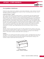
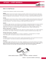
Cable Anchorage
The mains cable must be fixed securely with a 20mm cable gland. Remove a suitably located knockout
feed the cable through the gland and bolt the gland to the CF3000 backbox as shown. Secure the cable
to the side of the box using the cable clip provided.
NOTE: The mains cable tail ends must be insulated to prevent dangerous conditions arising in the event
of accidental switching on of the mains supply.
Section 1 - System Installation and Design
29
CF3000 - USER MANUAL
Installation
the panel should be installed in a clean, dry, reasonably well ventilated place, and not in direct sunlight.
Temperatures in excess of 40°C and below 5°C may cause problems, if in doubt consult Cooper Lighting
and Safety. The panel should be located away from any potential hazard, in a position where it is readily
accessible to authorised staff, and the fire services, ideally on the perimeter of a building near a
permanent entrance. Mount the panel to the wall using the drill template provided. Do not drill through the
panel to the wall as dust will contaminate the circuitry.
Installation Guide
! Never carry out insulation tests on cables connected to electronic equipment.
! DO NOT OVER TIGHTEN TERMINAL CONNECTOR SCREWS
! Always use the correct type of cables specifically designed for the operation of fire detection and
alarm circuits.
! Always adhere to volt drop limitation when sizing cables
! Always observe polarity throughout. Non colour coded conductors should be permanently identified.
! Screen continuity must be maintained throughout the entire loop circuit including at each junction
point and at each device, terminals are provided on each device to facilitate this.
! The screen should be earthed at the connection point provided at the CF3000 panel and not at any
other point. Both the loop start and the loop end must be connected to the appropriate earthing
points. Care must be taken to avoid connecting the screen to the earthed body of any metal devices,
enclosures or cable containment. The screen or drain wire of the loop cables should not be
considered as safety earth and therefore should not be connected to terminals marked with the earth
symbol, except at the panel, and should not be insulated with green and yellow sleeving.
! CF3000 utilises intelligent soft addressing technology to greatly simplify the installation and
commissioning processes. Once the system has been installed and the autolearn menu selected, the
CF3000 control panel will automatically scan the detection loops and allocate each device with an
address number corresponding with its position on the loop, this avoids the traditional need for
manual addressing of the system devices which is time consuming and provides a potential for error.
! It is of vital importance that accurate details are kept of the exact wiring route in order to determine
which address has been allocated to each device.
30
Section 1 - System Installation and Design
CF3000 - USER MANUAL
Fixing Details
Read all the installation instructions before commencing with the installation. The installation of this panel
must be carried out by a suitably qualified /trained person. Theinstallation must comply with IEE wiring
regulations and with BS5839 Pt 1 2002 The electronic components within the fire panel are Static
Sensitive. Do not touch the electronics directly.
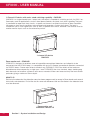
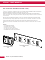
Mounting the Backbox
The CF3000 can be flush mount or surface mounted.
1. Surface Mount: Drill four holes and fix the backbox to the wall.
2. Flush Mount:
The backbox requires a hole 364 x 472 with a depth of 117mm (standard battery /
backbox ) or 217 mm if deep backbox is used.
Installing Cabling
Once the backbox is mounted the next stage is to install the power and loop cables and fit the glands.
479mm
400mm
227mm
364mm
309mm
117mm
132mm
472mm
Section 1 - System Installation and Design
31
CF3000 - USER MANUAL
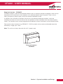
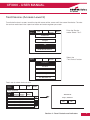
External Connections (Mains Supply)
The mains supply should be installed in accordance with the current edition of the IEE wiring regulations.
Connection to the mains supply must be via an isolating device (e.g. an isolating fuse rated at 3 Amps
maximum) reserved solely for the fire alarm system. The cover should be coloured red and labelled “FIRE
ALARM - DO NOT SWITCH OFF”. The isolating protective device should be secure from unauthorised
operation and ideally installed in a securely closed box with a breakable cover.
An additional warning label should be provided, depending on whether:
1. The isolating protective device is fed from the live side of the main isolating device in which case the
label on the isolating protective device, should read in addition - “WARNING: THIS SUPPLY REMAINS
ALIVE WHEN THE MAIN SWITCH IS TURNED OFF”. A further label should be placed on the main
isolating device reading “WARNING: THE FIRE ALARM SUPPLY REMAINS LIVE WHEN THIS SWITCH
IS TURNED OFF.
Or
2. If the isolating protective device is fed from the dead side of the main isolating device, a label should
be fixed to the main isolating device reading “WARNING: THIS SWITCH ALSO CONTROLS THE
SUPPLY TO THE FIRE ALARM SYSTEM”.
Distributed Power Supplies
The above also applies to any distributed power supply (i.e. mains connections for CF3000/PR repeat
units CSC354 relay units, etc.)
Cable Segregation
All cables for the fire alarm system should be segregated from any other cables/wiring/services.
Wiring configurations
Spurs can be taken off the loop in the following ways:
1. CZMU352 Addressable Interface - Allows up to 20 conventional smoke detectors and unlimited
FX501 / 503 callpoints.
2. Direct Loop Spur Wiring - Allows a zone of analogue detectors and callpoints to be directly spurred off
the loop
Note: The mains cable tail ends must be insulated to prevent dangerous conditions arising in the event
of accidental switching on of the mains supply.
32
Section 1 - System Installation and Design
CF3000 - USER MANUAL
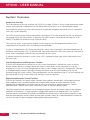
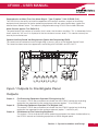
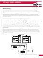
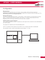
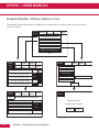
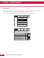
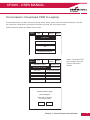
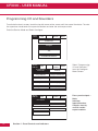
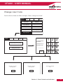
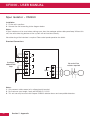
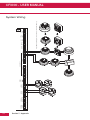
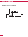
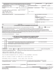
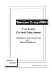
Networking
Up to 126 CF3000 panels or passive repeaters can be networked together to operate as a single
networked system. To achieve this each panel must be fitted with a network card (supplied at additional
cost.)
When operating as a networked system all fire and fault event information is displayed at every panel,
silencing and resetting of alarms can also be carried out from any panel on a networked system if panels
are suitably configured.
Networked panels are connected using a loop topology illustrated, or radial.
Networked panels can be used as active repeaters, alternatively a low cost passive repeater is available.
This can either be connected a loop of an individual panel or it can be connected to the network. The
recommended network cable for the network connection between panels is an enhanced Firetuf cable
Manufactured by Draka cables (part number 910234.) Screen continuity must be maintained throughout
the entire network circuit including at each junction point. The screen should only be earthed at the
connection point provided at the first panel and not at any other point. The screen or drain wire of the
network cable should not be considered as a safety earth and therefore should not be connected to
terminals marked with the earth symbol, except at the panel, and should not be insulated with green and
yellow sleeving.
Where the network cable passes between buildings, screen continuity should not be maintained from
building to building. A booster device must however be used irrespective of cable length and should be
fitted at a suitable point in the link between buildings. The cable screen should be connected to the earth
of one panel in each building.
Network Cable
Power
ON
FIRE
General
FAUL T
System
DISABLE
System
FAUL T
System
TEST
Battery
FAUL T
Charge
FA UL T
CF3000 ANALOGUE
ADDRESSABLE FIRE P
Power
ON
ANE L
FIRE
General
FA UL T
System
DISABLE
Zone s
1
2
3
4
5
6
7
13
14
15
16
17
18
19
29
30
25
37
26
27
28
38
39
40
51
52
63
64
41
42
53
54
31
43
8
20
9
11
2
3
4
5
6
7
14
15
16
17
18
19
29
30
System
TEST
8
Battery
FAUL T
Charge
FA UL T
9
10
47
59
60
49
50
55
56
70
71
72
61
62
66
67
68
82
83
84
73
74
75
76
77
78
79
80
81
82
94
95
96
85
86
87
88
89
90
91
92
93
94
68
76
77
78
79
80
81
87
88
89
90
91
92
93
23
36
25
48
37
Designed to EN54 parts 2 &
B
1
35
46
58
56
67
75
86
24
13
34
57
69
55
66
74
A
System
FA UL T
X
CF3000 ANALOGU E A DDRESSABLE FIRE P
PAANEL
NE L
Zone s
12
22
33
45
50
62
65
10
21
32
44
49
61
73
85
Y
26
27
28
38
39
40
51
52
4
63
64
41
42
53
54
65
31
43
20
11
12
21
22
23
32
33
34
35
44
45
46
47
57
58
59
60
69
70
71
72
83
84
95
24
96
36
48
Designed to EN54 parts 2 &
4
Network
Card
(Panel 1)
A
B
X
Y
Network
Card
(Panel 2)
Section 1 - System Installation and Design
33
CF3000 - USER MANUAL
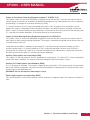
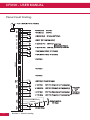
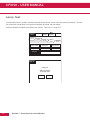
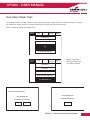
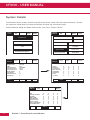
Input/Outputs
-
+
class change
Panel Inputs
Class Change: (option not required by EN54)
A pair of terminals are provided for class change. By shorting these terminals together (e.g. switch, time
clock) the alarm will sound (panel sounders + loop sounders only). The panel will not indicate a fire. The
alarm will cancel when the short circuit is removed. If the short circuit is not removed the alarms will not
cancel.
WARNING: No voltage should be applied to this input
Switch/Contactorb timer etc.
(Apply NO voltage)
Panel Outputs
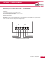
Panel Sounders: (option 7.8 EN54 Pt 2)
2 pairs of outputs are provided. ONLY polarised equipment should be used. Ensure the polarity of the
connections are observed at all times and end of line resistors (6k8 5%) are fitted for correct operation.
The total alarm load across all sounder outputs = 1.5 Amp All outputs are fused with 1.6 Amp Glass fuse
Alarm devices should be spread equally across the 4 sounder circuits.
WARNING: Do not exceed the rated output current
All sounders must be polarised
Both sounder circuits must
be terminated with a
6800 Ohm end of line resistor
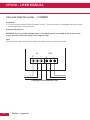
Output Fire Alarm Routing Equipment
(option 7.9 EN54 Pt 2)
This output, which is fused and monitored using a 6.8k end of line resistor, is used for the automatic
transmission of the fire signals to fire alarm routing equipment (e.g. fire brigade). It operates by providing
12 V output to an auxiliary device (e.g. relay). It is current limited to 30 mA using a resettable polyswitch.
Class change and test conditions do not operate this output. If operated under a fire alarm condition, the
indication will be displayed on the Touch screen display and will remain until the fire alarm is reset. Ensure
the polarity of the connections are observed at all times and end of line resistors (6k8 5%) are fitted for
correct operation.
34
Section 1 - System Installation and Design
CF3000 - USER MANUAL
Output to Fire Alarm Protecting Equipment (option 7.10 EN54 Pt 2)
This output, which is fused and monitored using 6.8k end of line resistor is used for the transmission of
the fire signals to controls for automatic fire protecting equipment (e.g. Door release units etc). It operates
by providing 24 V output to an auxiliary device (e.g. relay).
It is current limited to 30 mA using a resettable polyswitch. Class change and test conditions do not
operate this output. If operated under a fire alarm condition , this output remains activated until the fire
alarm is reset. Ensure the polarity of the connections is observed at all times and end of line resistors (6k8
5% ) are fitted for correct operation. All activated devices must be polarised.
Output to Fault Warning Routing Equipment (option 9.4.1c EN54 Pt 2)
This output, which is fused and monitored using 6.8k end of line resistor is used for the transmission of
fault signals to fault warning routing equipment This output is monitored using 6k8 end of line resistor and
it current limited to 30 mA.
Under normal conditions it operates by providing 24 V dc which can be connected directly to a 24 V
auxiliary device (relay). It is current limited to 30 mA. Under fault conditions or even if the CF3000 is
switched off, this output will switch to 0 V. Ensure the polarity of the connections is observed at all times
and end of line resistors (6k8 5%) are fitted for correct operation.
Auxiliary Relay (option not required by EN54)
This output is a volt free contact, which is protected by a polyswitch. It is rated at 24 V 1Amp. If operated
under a fire alarm condition, this output will remain energised until the fire alarm is reset.
Auxiliary DC Output (option not defined by EN54)
A 24 V dc output is provided. This output is protected by a polyswitch. This output can be used to power
fire or fault auxiliary equipment. Please ensure that all equipments connected to this output will only draw
current when a fire condition exists.
WARNING: Do not exceed the rated output current
Mimic Output (option not required by EN54)
This RS485 output is used to send data to a mimic display or a repeater panel. The maximum distance is
2km.
Section 1 - System Installation and Design
35
CF3000 - USER MANUAL
Maintainance
Daily Inspection
Check that only the green “POWER ON” indicator shows. Inspect for any fault indication. Notify any faults
to a system supervisior.
Weekly Test
Check indicators. Press supervisor mode on the top left of the touch screen. Enter passcode. Select
“others” tab. Press the button labeled weekly test, confirm you wish to perform the test and the amber
“System Test” LED will light. The panel will stay in the weekly test mode for 5mins before resetting. During
the weekly test, trigger a smoke detector or callpoint and check the fire panel registers the device and
illuminates the correct zonal indicator. Trigger a different device every time a weekly test is performed
ensuring devices are tested in rotation until all have been checked. It is advisable to develop a detailed a
building plan highlighting devices and locations to aid testing. The panel will reset automatically once the
5mins have elapsed. If no devices are triggered during the weekly test the panel will abort the test and
reset after 5mins. Record weekly test in the table provided in the log book.
Quarterly Test
Check all previous log book entries and verify that remedial action has been taken. Carry out the weekly
test. Visually examine the batteries and their connections, by loosening the screws behind printer door
and opening the hinged front from the right hand side. Disconnect the mains supply and check that the
batterry is capable of supplying the alarm sounders, by operating a callpoint.
Annual Test
As weekly test and quarterly test above. Additionally test all sensors and callpoints and check operation.
Every 2-3 Years
Replace or return the smoke detectors for cleaning to ensure correct operation and freedom from false
alarms. Special equipment is required for cleaning smoke detectors. Consult Cooper Lighting and Safety.
Every 5 Years
Replace sealed lead acid battery.
Cleaning
When cleaning the panel, use a moist cloth. Do not use solvents or harsh abrasives.
Printer Paper Order Code
Servicing: Cooper Lighting and Safety can offer a regular servicing contract.
Cooper Lighting and Safety
Service Division,
Wheatley Hall road
Doncaster
DN2 4NB.
Telephone: 01302 303352 Web: www.cooperfire.com
36
Section 1 - System Installation and Design
CF3000 - USER MANUAL
Section 2
Panel Assembly Information
Section 2 - Panel Assembly Information
37
CF3000 - USER MANUAL
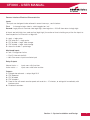
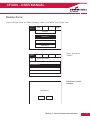
Attaching the Door
The door is designed as a drop on fit. Offer the door up to the back box in the open position as shown
below. Align the hinges and lower the door onto the hinge pins. Check the hinges are secure.
38
Section 2 - Panel Assembly Information
CF3000 - USER MANUAL
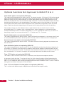
Installing a Hinged Cover
An option hinged cover is available as an optional extra item for CF3000. This can be fitted as standard
equipment prior to despatch or retro-fitted later. The method for fitting a cover is shown below.
Insert the bottom peg of the
hinged cover into the panel as
shown and close the hinged cover
followed by the printer door. Next
from the back of the panel insert
second peg though the hole
shown below and push into the
hinged cover
Section 2 - Panel Assembly Information
39
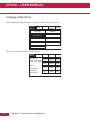
CF3000 - USER MANUAL
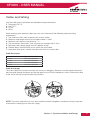
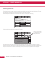
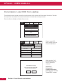
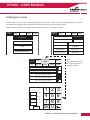
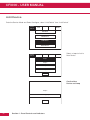
Fitting Printer Paper Roll
Open the printer access door on the right hand side of the panel using the key provided. Drop the paper
roll into the paper holder and feed paper into the printer. The printer will then automatically pull the paper
through if the panel is powered up. Tear off the excess paper them close and secure the printer access
door. Please note for paper feed to operate correctly, paper end must be straight
New paper roll simply drops into the holder.
Push paper underneath the roller as
shown until printer automatically
loads the paper. Tear off excess
paper and close the printer
compartment door.
40
Section 2 - Panel Assembly Information
CF3000 - USER MANUAL
Section 3
Commissioning
Section 3 - Commissioning
41
CF3000 - USER MANUAL
Commissioning Mode
Walk test mode allows a single engineer to test the various detectors and callpoints on a system without
always having to return to the panel either to reset the system or silence the alarms. When in
COMMISSIONING MODE, the system operates as normal except that when a detector or callpoint goes
into alarm, the alarms only operate for a few seconds and then will silence. The panel then tries to reset
the device automatically and, if successful, the alarms are operated again for a few seconds and the
installation engineer can move on to the next detector. After a full test has been carried out the engineer
can check the order in which the detectors/callpoints were operated using the DISPLAY LOG mode. This
information can also be printed on the optional printer.
When the panel is in “Walk Test Mode” the control panel inserts a different code into the log and also onto
the print-out. This is to distinguish between when a device has been tested in “Walk Test Mode” and
when a device has been triggered while in normal operation.
The following differences will occur:
1. When in the LOG mode, "One man walk test”" will appear on the display followed by the address text
and device type.
2. On the printout a “One man walk test” message will appear will appear followed by the address text
and device type.
3. During a real fire “FIRE !” Will appear on the display followed by the address text and device type.
42
Section 3 - Commissioning
CF3000 - USER MANUAL
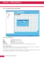
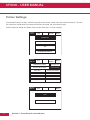
Configuration
DB Level Check
CF3000 includes the facility to test and set the system sounders with the minimum amount of
disturbance. In sounder test mode, the sounders will sound for 30 seconds on then 30 seconds off. This
facility can be accessed via the engineering menu.
Detector LED Flashing
The CF3000 detector flashing function is used to allow a visual inspection and confirmation that the fire
panel is in communication with the installed system devices. This facility can be accessed via the
engineering menu and can be switched on or off at any time as required.
Up/Downloading Using PC Software
The PC Software enables the address, location text, device type and any comments to be downloaded to
the CF3000 panels.
The software can download to all 126 networkable panels.
The PC is connected to each panel on the network in turn. All data for the panel is downloaded.
For networked systems, panels are identified by panel number, P1, P2 etc.
Powe r
ON
FIRE
General
FAUL T
System
DISABL E
System
FAUL T
System
TEST
Battery
FAUL T
Charge
FAUL T
Zones
1
2
3
4
5
6
7
13
14
15
16
17
18
19
20
21
22
25
26
27
28
29
30
31
32
33
34
35
8
9
10
11
23
12
24
36
37
38
39
40
41
42
43
44
45
46
47
49
50
51
52
53
54
55
56
57
58
59
60
61
62
63
64
65
66
67
68
69
70
71
72
73
74
75
76
77
78
79
80
81
82
83
84
85
86
87
88
89
90
91
92
93
94
95
96
48
Section 3 - Commissioning
43
CF3000 - USER MANUAL
Panel Fault Finding
V
= +5.5V ± 0.5V (No Printer Attached)
NO
C
S/C Fire
NC
AUX
RELAY
= O/C Normal
= S/C Normal
O/C Fire
+
FAULT
RELAY
= 12V No Fault
0V (short CCT) Fault
V
= 28.5V (No Load Connected)
V
= -O.6V-No Fire
28V Fire
V
= -O.6V-No Fire
28V Fire
V
= 22V (Device Fitted) 0V (Unused)
V
= 22V (Device Fitted) 0V (Unused)
+ 0V
+ 24V
O/P
V
-
FIRE P/E
-
+26V
FIRE R/E
+
}
No Fires
See Scope Plots for
Monitoring Condition
S+
SF-
LOOP 1
F+
S+
SF-
LOOP 2
= As Above
F+
S+
LOOP CIRCUITS
SF-
LOOP 3
= As Above
F+
S+
SF-
LOOP 4
= As Above
F+
+
CLASS
CHANGE
= 28V (Open Circuit, No Input)
V
= -0.6V Mon
+28V Fire (Depends on Programming)
V
= -0.6V Mon
+28V Fire (Depends on Programming)
V
= -0.6V Mon
+28V Fire (Depends on Programming)
V
= -0.6V Mon
+28V Fire (Depends on Programming)
+
V
1 +
2 -
SOUNDER
CIRCUIT 1
+
1 +
2 -
SOUNDER
CIRCUIT 2
Tx
Rx
CTS RTS
MODEM/PC
Rs232
OV
Tx+ Tx-
MIMIC
REPEATER
44
V 0V
V
Section 3 - Commissioning
V 9V
V 0V
}
V -9V
=0V (No Data)
Static Conditions
(No Data)
}
See Scope
Plots
for
Monitoring
Conditions
CF3000 - USER MANUAL
Protocol Format
Normal Communications to Devices:
With the command bits set for the 'Normal' command and the MSB of the three mode bits set at 0, this
shortened version of the normal communications to each device allows the analogue reply or status from
each device to be read. This format of communication is generally used throughout all background
supervision of the addressable loop.
Alarm Interrogate Command:
This command is seen by all devices on the loop, so no address byte is required, and is periodically sent
out during normal communications. This command allows any device experiencing an alarm condition to
respond, with callpoints given the highest priority, reporting their address. This causes the control panel
to break off from general background supervision of the loop and focus directly on the device in question.
Full Protocol Format:
With the command bits set for the 'Normal' command and the MSB of the three mode bits set at 1, the
long version of the normal communications can be sent to any device. This would normally be done by
the panel following a response to the alarm Interrogate command, allowing the panel to check the device
address, ID and confirm that the analogue reply, or status, is truly an alarm condition before actioning the
panel sounder outputs, for example.
Viewing the Voltage and Current waveforms at the panel:
Loop 1: Using a digital storage oscilloscope, connect one channel to R34 on the loop driver card;
probe 0V clip to the 'in-board' side of the resistor. This will display the loop current. Connect the
other channel to loop 1, S+ terminal on the main mother board. DO NOT connect the 0 V clip
of this probe.
Loop 2: Using a digital storage oscilloscope, connect one channel to R36 on the loop driver card;
probe 0 V clip to the 'in-board' side of the resistor. This will display the loop current. Connect
the other channel to loop 2, S+ terminal on the main mother board. DO NOT connect the 0 V
clip of this probe
Panel to Device
Device to Panel
1.1 ms
300us
2ms
300us
24v
typ
7.5v
0v
Mode
Byte 1
Byte 2
Byte 3
Parity
Command
Start
Response
8 bits
ID
5 bits
Flags
3 bits
A
Loop Current
Each Packet of Comms above must be separated by a gap of 20ms minimum where the line is held at 24v
Section 3 - Commissioning
45
CF3000 - USER MANUAL
PC Comissioning Software
Device Input Programming
Fire
Fault
Reset
Silence
Pre-Alarm
Non-Latching
panel reports fire from device.
panel reports fault from device.
panel resets.
silence all currently active sounders.
panel reports pre-alarm from device.
device won't latch in alarm condition, used in conjunction with isolates.
Isolate Zone / Address
user can define between zones or addresses to be isolated on activation of the device. The isolate list
button enables the user to enter upto 8 unique zones or addresses.
If non-latching has been enabled, Isolated devices can be un-isolated as the triggered device returns to
normal operation. (a callpoint keyswitch is an example for this application)
46
Section 3 - Commissioning
CF3000 - USER MANUAL
PC Comissioning Software
Device Outputs
Delay Configuration
The output of a device when triggered can be delayed - based on a user defined value in minutes.
This programming option is enabled when a value other than zero is entered inside the 'Delay' window.
MCP Override
This option is a manual intervention override, when enabled (check in box) the delay can be overridden
from any callpoint on the loop when triggered.
Section 3 - Commissioning
47
CF3000 - USER MANUAL
PC Comissioning Software
Panel Outputs
Dependency Type C
Each panel output can be assigned a unique list of zones derived from the zones available on the
loop, to activate this output, two unique zones from this list have to be in fire or alternatively any
zone outside this list will trigger the output also. When the 'Coincidence' box is checked - the
'Allocate device' button allows the user to populate this list.
48
Section 3 - Commissioning
CF3000 - USER MANUAL
Section 4
Panel Controls and Indicators
Section 4 - Panel Controls and Indicators
49
CF3000 - USER MANUAL
Panel Controls and Indicators
1.
2.
3.
4.
5.
System LED’s
Zonal LED’s
Touch Screen Display
Printer Access Door
Slot for Optional Printer
1
2
Powe r
ON
FIRE
General
FAUL T
4
3
System
DISABL E
System
FAUL T
System
TEST
Battery
FAUL T
Charge
FAUL T
Zones
1
2
3
4
5
6
7
13
14
15
16
17
18
19
20
21
22
25
26
27
28
29
30
31
32
33
34
8
9
10
11
23
12
24
35
36
37
38
39
40
41
42
43
44
45
46
47
48
49
50
51
52
53
54
55
56
57
58
59
60
65
68
61
62
63
64
66
67
69
70
71
72
73
74
75
76
77
78
79
80
81
82
83
84
85
86
87
88
89
90
91
92
93
94
95
96
5
1
Power
ON
2
3
4
5
FIRE
General
FAUL T
System
FAUL T
Power
FAUL T
6
Sounder
Disabl e
Faul t
7
System
DISABLE
8
System
TEST
9
10
FRE
Extinguisher
ACTIV ATED
Disable
Faul t
11
Delay
ACTIVE
Zones
LED
1
2
3
4
5
6
7
8
9
10
11
50
Name Function
Action
Power On Shows Panel is On
Fire Indicators Panel has Detected a Fire
General Fault Monitors Devices for Faults e.g. Smoke detectors/Sounders
System Fault Monitors Fire Panel for Faults
Power Fault Monitor Internal Battery Charger
Sounder Monitors Sounder Circuits/Indicates Disablement of this Output
System Disable Part of the System has been Disabled
System Test Supervisor/Engineer is Testing the System
FRE Monitors the FRE Circuit/Indicates Disablement of this Output
Extinguisher Activated Display Activatiion of Extinguishers (If Option Fitted)
Delay Active Delays on Outputs Active
Check Indicator is Illuminated
Impliment Fire Action Procedure
Report to System Supervisor
Report Fault to Service Dept
Report Fault to Service Dept
Report Fault to Service Dept
Report to System Supervisor
Check with System Supervisor
Report Fault to Service Dept
Check with System Supervisor
Check with System Supervisor
Section 4 - Panel Controls and Indicators
CF3000 - USER MANUAL
Panel Controls and Indicators
1.
2.
3.
4.
Log Book Storage
Insert Supervisor Key Here
Printer
Paper Roll Storage
2
1
Power
ON
FIRE
General
FAUL T
System
DISABLE
System
FAUL T
System
TEST
Battery
FAUL T
Charge
FAUL T
Zones
1
2
3
4
5
6
7
8
9
10
13
14
15
16
17
18
19
20
21
22
23
29
11
12
24
25
26
27
28
30
31
32
33
34
35
37
38
39
40
41
42
43
44
45
46
47
49
50
51
52
53
54
55
56
57
58
59
60
61
62
63
64
65
66
67
68
69
70
71
72
73
74
75
76
77
78
79
80
81
82
83
84
85
86
87
88
89
90
91
92
93
94
95
96
36
48
2
3
4
1
1.
2.
3.
4.
Optional Hinged Cover
Scroll Up
Mute Buzzer
Scroll Down
2
3
4
Section 4 - Panel Controls and Indicators
51
CF3000 - USER MANUAL
Touch Screen Display
Supervisor
FRE Off
Fire
0
Pre
Alarms 0
Faults
0
Disabled
/ Test
Systems Healthy
XX Zones Acitve
Tuesday
dd-mm-yyyy
16:25.25
BST On
The touch screen is a multi-function display consisting 320 x 240 dots featuring high intensity
backlighting. In normal operation, the display indicates as above with the backlighting off.
During an event on the system the display shows the FIRST EVENT and LAST EVENT plus other events
as space allows.
The last 2 lines are normally used to display the total number of events, but they are also used for
scrolling fire conditions, faults, pre alarms or disabled devices independently or for displaying a reduced
menu when in fire condition.
When an event occurs the Touch Screen backlighting comes on unless there is a mains
power supply fault.
Use the touch screen to scroll through all active events on the system by using the SCROLL UP and
SCROLL DOWN buttons (available at access level 1). You can display the contents of the log and also
view details of any fires, faults, pre-alarms,faults or disablements.. When displaying the system menu on
the touch screen, the last 5 lines of the display are shown in reverse text.
52
Section 4 - Panel Controls and Indicators
CF3000 - USER MANUAL
Panel Operation
CF3000 is operated via a backlit touch screen. The default fire screen is shown below. From this screen
all the panels functions can be operated. The first time you touch the screen the backlight will illuminate
the panel.
Supervisor
FRE Off
Fire
0
Pre
Alarms 0
Faults
0
Disabled
/ Test
Systems Healthy
XX Zones Acitve
Tuesday
dd-mm-yyyy
16:25.25
BST On
Pressing a field will highlight it and forward to the next screen as shown below.
Touch the screen here to view details
Supervisor
FRE Off
Fire
1
Pre
Alarms 0
Faults
0
Disabled
/ Test
Supervisor
FRE Off
Fire
1
First Fire
Systems Healthy
10 Zones Acitve
Total Fires = 1
Tuesday
dd-mm-yyyy
Tuesday
dd-mm-yyyy
16:25.25
BST On
16:25.25
BST On
Pre
Alarms 0
Faults
0
Disabled
/ Test
Meeting Room 1, Building 1, 1st floor
Loop: 1, Zone: 2, Type: Optical (150)
Print All
Help
Section 4 - Panel Controls and Indicators
53
CF3000 - USER MANUAL
Public (Access Level 1)
Public access level does not require an access code and allows anybody to review the functions outlined
below.
Public access level
Supervisor
FRE Off
Fire
0
Pre
Alarms 0
Faults
5
Disabled
/ Test
Systems Healthy
10 Zones Acitve
Tuesday
dd-mm-yyyy
16:25.25
BST On
Supervisor
Fire
1
FRE Off
Pre
Alarms 0
Faults
0
Disabled
/ Test
12:26:23 Device 1, Zone 1
Lp: 1, Ad:1, Z:1, Opto/thermal, [69]
First Fire
Supervisor
FRE off
Fires
0
Pre
Alarms 6
Faults
6
Show
Addresses
Show
Zones
Show
I/O
Show
Test Zone
Print All
Total Fires = 1
Help
Print All
Tuesday
dd-mm-yyyy
16:25.25
BST On
Supervisor
FRE off
Print All
54
Fires
0
Pre
Alarms 6
Faults
0
Disabled
/ Test
Help
Help
001
Device 2, Zone 1
Loop 1, Zone: 1, Type : Opto/thermal
002
Device 3, Zone 1
Loop 1, Zone: 1, Type : Opto/thermal
003
Device 4, Zone 1
Loop 1, Zone: 1, Type : Opto/thermal
004
Device 5, Zone 1
Loop 1, Zone: 1, Type : Opto/thermal
Supervisor
FRE off
Print All
Fires
0
Pre
Alarms 6
Faults
5
Help
001
03-Jun-03 12:51 Warning! : Device 1
Lp: 1, Ad: 1, Z: 1, Opto / Thermal [69]
001
03-Jun-03 12:51 Fault! : Device 1
Lp: 1, Ad: 1, Z: 1, Opto / Thermal [0]
002
03-Jun-03 12:51 Warning! : Device 2
Lp: 1, Ad: 2, Z: 1, Opto / Thermal [69]
002
03-Jun-03 12:51 Fault! : Device 2
Lp: 1, Ad: 2, Z: 1, Opto / Thermal [69]
003
03-Jun-03 12:51 Warning! : Device 3
Lp: 1, Ad: 3, Z: 1, Opto / Thermal [69]
003
03-Jun-03 12:51 Fault! : Device 3
Lp: 1, Ad: 3, Z: 1, Opto / Thermal [69]
004
03-Jun-03 12:51 Warning! : Device 4
Lp: 1, Ad: 4, Z: 1, Opto / Thermal [69]
004
03-Jun-03 12:51 Fault! : Device 4
Lp: 1, Ad: 4, Z: 1, Opto / Thermal [69]
005
03-Jun-03 12:51 Warning! : Device 5
Lp: 1, Ad: 5, Z: 1, Opto / Thermal [69]
005
03-Jun-03 12:51 Fault! : Device 5
Lp: 1, Ad: 5, Z: 1, Opto / Thermal [69]
Section 4 - Panel Controls and Indicators
Disabled
/ Test
Disabled
/ Test
CF3000 - USER MANUAL
Evacuate (Access Level 2)
To activate the touch screen, touch the top left corner of the screen until the screen illuminates. To enter
the supervisor mode touch the supervisor button and enter the passcode.
Enter the Supervisor Mode Passcode and select “Evacuate” on the menu at the top of the screen.
Supervisor
FRE off
View Fires
AC = 0
Evacuate
View Pre
Alarms
Silence
Alarms
View
Disabled
Mute
Buzzer
View
Faults
Reset
Others
Pre-alarm = Some smoke / heat but below fire threshold
these warnings will appear and disappear
Select “Yes” to evacuate the building.
Supervisor
FRE Off
This will activate ALL sounders
and activate all panel relays
Do you wish to continue?
Yes
No
Section 4 - Panel Controls and Indicators
55
CF3000 - USER MANUAL
Silence Alarms
To activate the touch screen, touch the top left corner of the screen until the screen illuminates. To enter
the supervisor mode touch the supervisor button and enter the passcode.
Enter the Supervisor Mode Passcode and select “Silence Alarms” button as the top of
Supervisor
FRE off
View Fires
AC = 0
Evacuate
View Pre
Alarms
Mute
Buzzer
Silence
Alarms
View
Faults
View
Disabled
Zone: 0
I/O
Address: 0
Touch button to view list
Select “yes” to silence Alarm.
Supervisor
FRE Off
This will silence ALL sounders
Do you wish to continue?
Yes
56
Section 4 - Panel Controls and Indicators
No
Reset
Others
CF3000 - USER MANUAL
Mute Buzzer
To activate the touch screen, touch the top left corner of the screen until the screen illuminates. To enter
the supervisor mode touch the supervisor button and enter the passcode.
Enter the Supervisor Mode and Select “Mute Buzzer” from the Top Menu
Supervisor
FRE off
View Fires
AC =19
Evacuate
View Pre
Alarms
Silence
Alarms
View
Disabled
Mute
Buzzer
View
Faults
Reset
Others
Enable / Disable
Weekly Test
Send Log to PC
Print
Veiw Log
Check Config.
Lamp Test
Send Analogue Value to PC
Reset
Enter the Supervisor Mode and Select “Reset” from the top Menu. Select “Yes” to reset the panel.
Supervisor
FRE off
View Fires
AC =19
001
Evacuate
View Pre
Alarms
Silence
Alarms
Mute
Buzzer
Reset
Supervisor
FRE Off
Others
View
Disabled
View
Faults
The panel will reset
Do you wish to continue?
14:22:49
Mains Failure
Yes
No
Faults = Short circuits, broken detectors etc.
To remove faults from this list:
1) Fix Fault
2) Reset Panel
Section 4 - Panel Controls and Indicators
57
CF3000 - USER MANUAL
Pre-Alarms
Enter the Supervisor Mode and Select “Pre-Alarms” tab.
Supervisor
FRE off
View Fires
AC = 0
Evacuate
View Pre
Alarms
Silence
Alarms
View
Disabled
Mute
Buzzer
View
Faults
Reset
Others
Pre-alarm = Some smoke / heat but below fire threshold
these warnings will appear and disappear
A pre-alarm is shown when a detector appears to register heat or smoke but in a quantity that is
insufficient to warrant an alarm. Pre-alarm may indicate a build up of dirt in a smoke detector which can
be interpreted by the detector as smoke presence.
Disabled Devices
Enter the Supervisor mode and Select the “Disabled” tab.
Supervisor
FRE off
View Fires
AC = 0
Evacuate
View Pre
Alarms
Silence
Alarms
View
Disabled
Mute
Buzzer
View
Faults
Reset
Others
Zone: 0
I/O
Address: 0
Touch button to view list
The individual buttons show which devices and the number of devices which have been disabled. Press
one of the buttons to display detailed information for a particular category
58
Section 4 - Panel Controls and Indicators
CF3000 - USER MANUAL
Faults
Enter Supervisor Mode Passcode and select “Faults” tab.
Supervisor
FRE off
Fires
AC = 0
Evacuate
View Pre
Alarms
Silence
Alarms
Mute
Buzzer
Reset
Others
View
Disabled
View
Faults
Pre-alarm = Some smoke / heat but below fire threshold
These warnings will appear and disappear
Enable/Disable (Others Menu)
To activate the touch screen, touch the top left corner of the screen until the screen illuminates. To enter
the supervisor mode touch the supervisor button and enter the passcode
Enter the Supervisor Mode passcode and select the “Others” tab.
Supervisor
FRE off
Fires
AC = 0
Evacuate
View Pre
Alarms
Silence
Alarms
View
Disabled
Mute
Buzzer
View
Faults
Reset
Others
Enable / Disable
Weekly Test
Send Log to PC
Print
Veiw Log
Check Config.
Lamp Test
Send Analogue Value to PC
Section 4 - Panel Controls and Indicators
59
CF3000 - USER MANUAL
Enable/Disable (Others Menu) Cont.
The Enable/Disable feature allows the operator to disable part or a whole system by the sub menus
shown on the left.
Supervisor
FRE Off
Evacuate
Silence
Alarms
Mute
Buzzer
Reset
Network Enable / Disable
Enable / Disable Zone
Enable / Disable I/O
Enable All
Enable / Disable Address
Exit
Supervisor
FRE Off
Evacuate
Silence
Alarms
Mute
Buzzer
Reset
Show
All
Show
Detectors
Show
Alarms
Show
I/O Units
Exit
Supervisor
FRE Off Evacuate
Device 1, Zone 1
Loop 1, Zone 1, Type: Optical / Thermal
Enable
Fire Protection: Enabled
002
Device 2, Zone 1
Loop 1, Zone 1, Type: Optical / Thermal
Disable
Delayed: Enabled
003
Device 3, Zone 1
Loop 1, Zone 1, Type: Optical / Thermal
Disable
Aux Realy: Enabled
004
Device 4, Zone 1
Loop 1, Zone 1, Type: Optical / Thermal
Enable
Fault Realy: Enabled
005
Device 5, Zone 1
Loop 1, Zone 1, Type: Optical / Thermal
Disable
Exit
Evacuate
Silence
Alarms
Mute
Buzzer
Mute
Buzzer
Fire Relay: Enabled
Exit
Reset
Supervisor
FRE Off
Touch “Enabled” button to Disable
Touch “Disabled” button to Enalbe
Zone 001 Zone 1
Enable
Enable all devices?
Zone 002 Zone 2
Disable
Do you want to continue?
Zone 003 Zone 3
Disable
Zone 004 Zone 4
Enable
Yes
Section 4 - Panel Controls and Indicators
Reset
Fire Routing: Enabled
001
Supervisor
FRE Off
60
Silence
Alarms
No
CF3000 - USER MANUAL
Print
To activate the touch screen, touch the top left corner of the screen until the screen illuminates. To enter
the supervisor mode touch the supervisor button and enter the passcode.
Enter the Supervisor Mode and Select the “Others” Tab. Press “Print”
Supervisor
FRE off
Fires
AC = 19
Silence
Alarms
Evacuate
View Pre
Alarms
View
Disabled
Mute
Buzzer
View
Faults
Reset
Others
Enable / Disable
Weekly Test
Send Log to PC
Print
Veiw Log
Check Config.
Lamp Test
Send Analogue Value to PC
Select the Information You wish to Print from the Buttons Listed.
Service
FRE off
Evacuate
Silence
Alarm
Mute
Buzzer
Reset
Print All Log Records
Print Fire Log
Print last 10 Log Records
Print Fault Log
Print Disablement
Print Test Log
Print Current Faults
Print Current Files
Exit
Section 4 - Panel Controls and Indicators
61
CF3000 - USER MANUAL
Lamp Test
To activate the touch screen, touch the top left corner of the screen until the screen illuminates. To enter
the supervisor mode touch the supervisor button and enter the passcode.
Enter the Supervisor Mode and Select the “Others” Tab. Press “Lamp Test”
Supervisor
FRE off
Fires
AC = 19
Mute
Buzzer
Silence
Alarms
Evacuate
View Pre
Alarms
View
Disabled
View
Faults
Others
Enable / Disable
Weekly Test
Send Log to PC
Print
Veiw Log
Check Config.
Lamp Test
Send Analogue Value to PC
Supervisor
FRE Off
Lamp Test
LED’s will light in
numerical order
Yes
62
Reset
Section 4 - Panel Controls and Indicators
No
CF3000 - USER MANUAL
Weekly Test
To activate the touch screen, touch the top left corner of the screen until the screen illuminates. To enter
the supervisor mode touch the supervisor button and enter the passcode. Select the others tab as
shown below. Press Weekly test.
Supervisor
FRE off
Fires
AC = 19
Evacuate
View Pre
Alarms
Silence
Alarms
View
Disabled
Mute
Buzzer
View
Faults
Reset
Others
Enable / Disable
Weekly Test
Send Log to PC
Print
Veiw Log
Check Config.
Lamp Test
Send Analogue Value to PC
Weekly test is now in progress.
Supervisor
FRE Off
* Features outside EN54 spec
Weekly Test
Do you want to continue?
Weekly Test
Awaiting alarm signal
Will rest after 4 minutes
Yes
No
Cancel
The panel will automatically return to the system healthy screen once the weekly test has been
completed.
Section 4 - Panel Controls and Indicators
63
CF3000 - USER MANUAL
Viewing Events
To activate the touch screen, touch the top left corner of the screen until the screen illuminates. To enter
the supervisor mode touch the supervisor button and enter the passcode.
Enter the Supervisor Mode Passcode. Select the “Others” tab and press View Log.
Supervisor
FRE off
Evacuate
Fires
AC = 19
View Pre
Alarms
Silence
Alarms
View
Disabled
Mute
Buzzer
View
Faults
Reset
Others
Enable / Disable
Weekly Test
Send Log to PC
Print
Veiw Log
Check Config.
Lamp Test
Send Analogue Value to PC
Use the scroll bar to view the list of upto 1000 events.
Silence
Alarms
Supervisor
FRE off
Evacuate
Newest
Oldest
Exit
Show
All
Show
Fires
Show
Faults
Mute
Buzzer
Reset
Events can be sorted
by selecting from the
sort option menu.
Show
Tests
001
Monday 13-Jan-2004 08:34:12
Hard Reset
002
FIRE! Lobby, [Optional] (Ana=150)
Building 1, Ground flour, Panel 1, Loop1, device 1
003
Monday 06-Nov-2000 11:22:12
Soft Reset
004
Monday 13-Nov-2001 11:22:12 Fault
Panel 1, Loop1, device 1
005
Monday 18-Feb-2001 22:20:18
Mains or battery failure
The CF3000 event log stores up to 1000 events including, fires, faults, resets and address changes.
Once the maximum 1000 events has been reached CF3000 will automatically overwrite the oldest event
every time a new event is stored. The event log can only be reset by an approved service engineer.
64
Section 4 - Panel Controls and Indicators
CF3000 - USER MANUAL
Check Auto Config
To activate the touch screen, touch the top left corner of the screen until the screen illuminates. To enter
the supervisor mode touch the supervisor button and enter the passcode.
Enter the Supervisor Mode and Select the “Others” Tab. Press Check Auto Config. This feature will scan
the loop and pinpoint the exact location of any break in the loop wiring and will also identify any changes
in the loop configuration (e.g. New devices added or changed device types).
Supervisor
FRE off
Fires
AC = 0
Evacuate
View Pre
Alarms
Silence
Alarms
View
Disabled
Mute
Buzzer
View
Faults
Reset
Others
Enable / Disable
Weekly Test
Send Log to PC
Print
Veiw Log
Check Config.
Lamp Test
Send Analogue Value to PC
Supervisor
FRE Off
Check Auto Config
Replace Device
Exit
Supervisor
FRE Off
Check
Auto Config
Yes
No
Section 4 - Panel Controls and Indicators
65
CF3000 - USER MANUAL
Replace Device
Replace device enables an existing device to be replaced with a new device without losing the existing
text and sounder programming. Replace a single device then use use the replace device menu to allocate
an existing address to the new device
Supervisor
FRE off
Fires
AC = 0
Evacuate
View Pre
Alarms
Silence
Alarms
View
Disabled
Mute
Buzzer
View
Faults
Reset
Others
Enable / Disable
Weekly Test
Send Log to PC
Print
Veiw Log
Check Config.
Lamp Test
Send Analogue Value to PC
Supervisor
FRE Off
Check Auto Config
Replace Device
Exit
Supervisor
FRE off
Supervisor
FRE off
Select a Loop
Enter Loop 1 Address
Loop 1
Loop 2
Exit
66
Section 4 - Panel Controls and Indicators
Exit
0 1 2 3
Del 4 5 6
OK 7 8 9
CF3000 - USER MANUAL
Test Device (Access Level 3)
To activate the touch screen, touch the top left corner of the screen until the screen illuminates. To enter
the service mode touch the supervisor button and enter engineer passcode.
Service
FRE off
Mute
Buzzer
Exit
Reset
Enter the Service
mode. Select “Test”.
Reset
Select the
“Test Device” button.
Commission
Configure
Test
Enable/Disable Address
Service
FRE off
Mute
Buzzer
Exit
Test Device
Test Zone
Sounder Level Test Mode
Globle Flashing LED on/ff
One Walk Walk Test
Touch row to select device to test.
Service
FRE off
Exit
Reset
Touch row to test
Show
All
001
Show
Detectors
Show
Alarms
Show
Relay
Lobby, Building 1, 1st Floor
Loop 1, Zone 2, Type: Optical
002
Main Reception, Building 1, 1st Floor
Loop 1, Zone 2, Type: Optical
003
Storage / archive, Building 1, 1st Floor
Loop 1, Zone 2, Type: Optical
004
Meeting Room 1, Building 1, 1st Floor
Loop 1, Zone 2, Type: Optical
Test Devises
Loop 1, Address 1
Yes
No
Section 4 - Panel Controls and Indicators
67
CF3000 - USER MANUAL
Test Zone
To activate the touch screen, touch the top left corner of the screen until the screen illuminates. To enter
the supervisor mode touch the supervisor button and enter the service passcode.
Enter the Service Mode, Select “Test” and on the Screen Shown Below Press “Test Zone”
Service
FRE off
Mute
Buzzer
Exit
Reset
Test Device
Test Zone
Sounder Level Test Mode
Globle Flashing LED on/ff
One Walk Walk Test
Service
FRE off
Reset
Exit
Touch “_” Button to place a zone into test mode
Touch “_” Button to remove a zone into test mode
Zone 001 Building 1, Ground
Zone 002 Building 1, 1st Floor
Test
Zone 003 Building 1, 2nd Floor
_
Zone 004 packing & Stores
_
Zone 005 Building 2, Basement
68
_
Section 4 - Panel Controls and Indicators
_
CF3000 - USER MANUAL
Sounder Level Test Mode
Enter the Service Mode and Select Test. From the Test Menu Select “Sounder Level Test Mode”
Service
FRE off
Mute
Buzzer
Exit
Service
FRE off
Reset
Mute
Buzzer
Exit
Reset
Test Device
Commission
Test Zone
Configure
Sounder Level Test Mode
Test
Globle Flashing LED on/ff
Enable/Disable Address
One Walk Walk Test
Sound Level Test Mode
Do you want to continue?
Yes
No
Sound Level Test Mode
All sounders will now pulse
15 seconds on, 30 seconds off
Touch “Stop” button to stop test
Stop
Section 4 - Panel Controls and Indicators
69
CF3000 - USER MANUAL
Global Flashing LED On/Off
To activate the touch screen, touch the top left corner of the screen until the screen illuminates. To enter
the supervisor mode touch the supervisor button and enter the service passcode.
Enter the Service Mode and Select Test.
Service
FRE off
Mute
Buzzer
Exit
Reset
Commission
Configure
If global LED flashing is
set to on, all device
LED’s will pulse
intermittently to
confirm correct
communication.
Test
Enable/Disable Address
Service
FRE off
Mute
Buzzer
Exit
Test Device
Test Zone
Sounder Level Test Mode
Globle Flashing LED on/ff
One Walk Walk Test
Global Flashing LED’s
Flashing
70
Section 4 - Panel Controls and Indicators
Off
Reset
Select “Global Flashing
LED On/Off” from the
Test Menu Screen.
CF3000 - USER MANUAL
One Man Walk Test
To activate the touch screen, touch the top left corner of the screen until the screen illuminates. To enter
the supervisor mode touch the supervisor button and enter the service passcode.
Enter the Service Mode and Select Test.
Service
FRE off
Mute
Buzzer
Exit
Reset
Commission
Configure
Test
Enable/Disable Address
Service
FRE off
Mute
Buzzer
Exit
Reset
Select “One Man
Walk Test” from the
Test Menu Screen.
Test Device
Test Zone
Sounder Level Test Mode
Globle Flashing LED on/ff
One Walk Walk Test
* Features outside EN54 spec
One Man Walk test
Do you want to continue?
Yes
No
One Man Walk Test
Awaiting Alarm Signal
Stop
Section 4 - Panel Controls and Indicators
71
CF3000 - USER MANUAL
Commission: Load CDR from Laptop
To activate the touch screen, touch the top left corner of the screen until the screen illuminates. To enter
the supervisor mode touch the supervisor button and enter the service passcode.
Enter the Service Mode and Select Commission.
Service
FRE off
Mute
Buzzer
Exit
Reset
Commission
Configure
Test
Enable/Disable Address
Service
FRE Off
Exit
Mute
Buzzer
Reset
Load CDR from Laptop
Analogue Level
Dowload CDR to Laptop
Printer Settings
Auto Learn
Change Panel Number
Erase Log
Number of Panel
in Network
Systems Detail
Screen Cover
Load Logo From PC
Italian Mode
Select “Load CDR
from Laptop” from the
Commission Menu”
After pressing “Yes”
click commission on
the PC download
software.
Load CDR from Laptop
This will erase the current CDR
Do you want to continue?
Yes
72
Section 4 - Panel Controls and Indicators
No
Important:
Do not click
commission before
pressing “Yes” on the
“Load CDR” screen.
CF3000 - USER MANUAL
Commission: Download CDR to Laptop
To activate the touch screen, touch the top left corner of the screen until the screen illuminates. To enter
the supervisor mode touch the supervisor button and enter the service passcode.
Enter the Service Mode and Select Commission.
Service
FRE off
Mute
Buzzer
Exit
Reset
Commission
Configure
Test
Enable/Disable Address
Service
FRE Off
Mute
Buzzer
Exit
Reset
Load CDR from Laptop
Analogue Level
Dowload CDR to Laptop
Printer Settings
Auto Learn
Change Panel Number
Erase Log
Number of Panel
in Network
Systems Detail
Screen Cover
Load Logo From PC
Italian Mode
Select “Download CDR
from Laptop” from the
Commission Menu
Screen.
Download CDR to Laptop
Start PC Program
Press “OK” to continue
Or “Cancel” to Exit
Ok
Cancel
Section 4 - Panel Controls and Indicators
73
CF3000 - USER MANUAL
Commission: Auto Learn
To activate the touch screen, touch the top left corner of the screen until the screen illuminates. To enter
the supervisor mode touch the supervisor button and enter the service passcode.
Enter the Service Mode and Select Commission.
Service
FRE off
Mute
Buzzer
Exit
Reset
Commission
Configure
Test
Enable/Disable Address
Load CDR from Laptop
Analogue Level
Dowload CDR to Laptop
Printer Settings
Auto Learn
Change Panel Number
Erase Log
Number of Panel
in Network
Systems Detail
Screen Cover
Load Logo From PC
Italian Mode
Service
FRE off
Exit
Auto Learn
Do you want to continue?
No
Pre- Addressed Auto Learn
Yes - Autolearn All Loops
74
Section 4 - Panel Controls and Indicators
Select “Auto Learn”
from the Configure
Menu Screen.
Important:
Activating autolearn
will erase all existing
programming, text
and configuration
data.
CF3000 - USER MANUAL
Erase Log
To activate the touch screen, touch the top left corner of the screen until the screen illuminates. To enter
the supervisor mode touch the supervisor button and enter the service passcode.
Enter the Service Mode and Select Commission.
Service
FRE off
Mute
Buzzer
Exit
Reset
Commission
Configure
Test
Enable/Disable Address
Service
FRE Off
Mute
Buzzer
Exit
Reset
Load CDR from Laptop
Analogue Level
Dowload CDR to Laptop
Printer Settings
Auto Learn
Change Panel Number
Erase Log
Number of Panel
in Network
Systems Detail
Screen Cover
Load Logo From PC
Italian Mode
Select “Erase Log
and Reset” from the
Configure Menu
Screen.
This will delete all log entries
Do you want to continue?
Yes
No
Section 4 - Panel Controls and Indicators
75
CF3000 - USER MANUAL
System Details
To activate the touch screen, touch the top left corner of the screen until the screen illuminates. To enter
the supervisor mode touch the supervisor button and enter the service passcode.
Enter the Service Mode and Select Commission, then Press “System Details”.
Service
FRE off
Mute
Buzzer
Exit
Service
FRE Off
Reset
Commission
Enable/Disable Address
Service
FRE Off
Print
Program
Program Data
CDR
CDR Checksum
Loop Controller 1
Loop Controller 2
Panel Number
Total Panels
Total Addresses
Total Zones
Page 1
Page 2
Exit
Analogue Level
Dowload CDR to Laptop
Printer Settings
V3.02.01
22/01.08
V0.5
0xF7D95E
V2.1.4
V0.0.0
0
1
13
4
Page 3
Change Panel Number
Erase Log and Reset
Number of Panel
in Network
Systems Detail
Screen Cover
Load Logo From PC
Italian Mode
Exit
Print
Reset
Loop 1 Loop 2 Loop 3
Optical
Ionisation
Thermal A1R
Opto / Thermal
Thermal BS
Thermal CS
Alarm
I / O Units
Page 4
Print
SCU
Voice Annunciator
Repeater
ZMU / {SUM
Beam Detector
Technical Timer
Access Control
Emerg.Light.Module
Carbon Monoxide
Page 1
Page 2
Page 1
Page 5
Service
FRE Off
76
Auto Learn
Service
FRE Off
Reset
Page 2
Exit
Reset
Loop 1
Loop 2
Loop 3
0
13
0
0
0
2
0
0
0
0
14
0
0
0
1
0
0
0
0
0
0
0
0
0
0
0
0
Page 3
Section 4 - Panel Controls and Indicators
Page 4
Reset
Load CDR from Laptop
Configure
Test
Mute
Buzzer
Exit
Loop 4
0
0
0
0
0
0
0
0
0
Page 5
0
13
0
0
0
2
0
0
0
14
0
0
0
1
0
0
Page 3
0
0
0
0
0
0
0
0
Page 4
Loop 4
0
0
0
0
0
0
0
0
Page 5
CF3000 - USER MANUAL
Analogue Level
To activate the touch screen, touch the top left corner of the screen until the screen illuminates. To enter
the supervisor mode touch the supervisor button and enter the service passcode.
Enter the Service Mode and Select Commission then press “Analogue Levels”.
Service
FRE off
Mute
Buzzer
Exit
Service
FRE Off
Reset
Commission
Configure
Test
Enable/Disable Address
Service
FRE Off
Exit
Goto
Show
All
Show
Detectors
Show
Optical
Device 1, Zone 1
Loop: 1, Zone 1, Type: Opto / Thermal
Device 2, Zone 1
Loop: 1, Zone 1, Type: Opto / Thermal
003
Device 3, Zone 1
Loop: 1, Zone 1, Type: Opto / Thermal
004
Device 4, Zone 1
Loop: 1, Zone 1, Type: Opto / Thermal
005
Device 5, Zone 1
Loop: 1, Zone 1, Type: Opto / Thermal
Enter Address
..............................
Loop 1
0 - 13
Loop 2
0-0
Loop 3
0-0
Loop 4
0-0
Cancel
Analogue Level
Dowload CDR to Laptop
Printer Settings
Auto Learn
Change Panel Number
Erase Log and Reset
Number of Panel
in Network
Systems Detail
Screen Cover
Load Logo From PC
Italian Mode
Show
Show
Ionisation Thermal
002
1
4
7
ok
Reset
Load CDR from Laptop
Reset
001
Mute
Buzzer
Exit
Note:
Go to command can
be used to jump to a
specific address
2 3
5 6
8 9
0
Section 4 - Panel Controls and Indicators
77
CF3000 - USER MANUAL
Printer Settings
To activate the touch screen, touch the top left corner of the screen until the screen illuminates. To enter
the supervisor mode touch the supervisor button and enter the service passcode.
Enter the Service Mode and Select Commission then press “Printer settings”.
Service
FRE off
Mute
Buzzer
Exit
Reset
Commission
Configure
Test
Enable/Disable Address
Service
FRE Off
Mute
Buzzer
Exit
Load CDR from Laptop
Analogue Level
Dowload CDR to Laptop
Printer Settings
Auto Learn
Change Panel Number
Erase Log and Reset
Number of Panel
in Network
Systems Detail
Screen Cover
Load Logo From PC
Italian Mode
Service
FRE Off
Exit
Reset
Auto
Request
78
Reset
Section 4 - Panel Controls and Indicators
CF3000 - USER MANUAL
Change Panel Number
To activate the touch screen, touch the top left corner of the screen until the screen illuminates. To enter
the supervisor mode touch the supervisor button and enter the service passcode.
Enter the Service Mode and Select Commission then press “Change Panel Number”
Service
FRE off
Mute
Buzzer
Exit
Reset
Commission
Configure
Test
Enable/Disable Address
Service
FRE Off
Mute
Buzzer
Exit
Reset
Load CDR from Laptop
Analogue Level
Dowload CDR to Laptop
Printer Settings
Auto Learn
Change Panel Number
Erase Log and Reset
Number of Panel
in Network
Systems Detail
Screen Cover
Load Logo From PC
Italian Mode
Change Panel Number
0..............................
Cancel
1
4
7
ok
2 3
5 6
8 9
0
Section 4 - Panel Controls and Indicators
79
CF3000 - USER MANUAL
Number of Panels in Network
To activate the touch screen, touch the top left corner of the screen until the screen illuminates. To enter
the supervisor mode touch the supervisor button and enter the service passcode.
Enter the Service Mode and Select Commission then press “Number of Panels in Network”
Service
FRE off
Mute
Buzzer
Exit
Reset
Commission
Configure
Test
Enable/Disable Address
Service
FRE Off
Reset
Load CDR from Laptop
Analogue Level
Dowload CDR to Laptop
Printer Settings
Auto Learn
Change Panel Number
Erase Log and Reset
Number of Panel
in Network
Systems Detail
Screen Cover
Load Logo From PC
Italian Mode
Number of Panels
In Network
1..............................
Cancel
80
Mute
Buzzer
Exit
1
4
7
ok
Section 4 - Panel Controls and Indicators
2 3
5 6
8 9
0
CF3000 - USER MANUAL
Screen Cover
To activate the touch screen, touch the top left corner of the screen until the screen illuminates. To enter
the supervisor mode touch the supervisor button and enter the service passcode.
Enter the Service Mode and Select Commission then press “Screen Cover”
Service
FRE off
Mute
Buzzer
Exit
Reset
Commission
Configure
Test
Enable/Disable Address
Service
FRE Off
Mute
Buzzer
Exit
Reset
Load CDR from Laptop
Analogue Level
Dowload CDR to Laptop
Printer Settings
Auto Learn
Change Panel Number
Erase Log and Reset
Number of Panel
in Network
Systems Detail
Screen Cover
Load Logo From PC
Italian Mode
Service
FRE Off
Exit
Reset
Installed
Not Required
Section 4 - Panel Controls and Indicators
81
CF3000 - USER MANUAL
Programming I/O and Sounders
To activate the touch screen, touch the top left corner of the screen until the screen illuminates. To enter
the supervisor mode touch the supervisor button and enter the service passcode.
Enter the Service Mode and Select Configure.
Service
FRE off
Mute
Buzzer
Exit
Reset
Commission
Configure
Test
Enable/Disable Address
Service
FRE Off
Exit
Reset
Programming I/O
and Sounders
Add/Delete
Change Date/Time
Configure Heat Detectors
Change Text
Network
Configure Zones
Language
Change Passcode
Day / Night
Service
FRE Off
Exit
Mute
Buzzer
Reset
Panel Outputs
T1/T2
Auxiliary Board
Alarm Verification Feature
HMO
FRE Double Knock Override
Sounder Tone
82
Mute
Buzzer
Section 4 - Panel Controls and Indicators
Select “Programming
I/O and Sounders””
from the Configure
Menu Screen.
Press panel outputs Note:
Interface
Inputs/Interface
Outputs are only
used in certain
export markets
CF3000 - USER MANUAL
Sound Settings
Touch sound settings.
Service
FRE Off
Exit
Reset
Sound Settings
Selections from the screens below will become the global settings for all loop sounders.
Service
FRE Off
Exit
Reset
Service
FRE Off
Exit
Reset
Volume
This will efffect all sounders
Volume
Low
Medium
Sound
Service
FRE Off
Exit
High
Reset
Service
FRE Off
Exit
Reset
Volume
This will efffect all sounders
Volume
Slow Loop
Two Tone
Sound
Continuous
Section 4 - Panel Controls and Indicators
83
CF3000 - USER MANUAL
Change Date/Time
Enter the Service Mode and Select Configure. Select Change Date/Time.
Service
FRE Off
Mute
Buzzer
Exit
Reset
Programming I/O
and Sounders
Add/Delete
Change Date/Time
Configure Heat Detectors
Change Text
Network
Configure Zones
Language
Change Passcode
Set the Time Using the Buttons Shown Below.
Service
FRE Off
OK
Reset
+1
Hour
+ 10
Minutes
+1
Minute
-1
Hour
- 10
Minutes
-1
Minute
Current Date:
+1
Day
+ 10
Month
+1
Year
Wednesday
dd-mmm-yyyy
-1
Day
- 10
Month
-1
Year
Current Time:
10:10:04
BST On
84
Cancel
Section 4 - Panel Controls and Indicators
CF3000 - USER MANUAL
Change Address Text
Enter the Service Mode and Select Configure. Select “Change Text”
Service
FRE Off
Mute
Buzzer
Exit
Reset
Programming I/O
and Sounders
Add/Delete
Change Date/Time
Configure Heat Detectors
Change Text
Network
Configure Zones
Language
Change Passcode
Press “Change Address Text”
Service
FRE off
Mute
Buzzer
Exit
Reset
Change Address Text
Change Zone Text
Change Panel
Select the Address you wish to change and edit using the keyboard
Service
FRE Off
Exit
Show
All
Show
Detectors
Reset
Show
Alarms
Name for address 1
Show
I/O Units
001
Device 1, Zone 1
Loop: 1, Zone 1, Type: Opto / Thermal
002
Device 2, Zone 1
Loop: 1, Zone 1, Type: Opto / Thermal
003
Device 3, Zone 1
Loop: 1, Zone 1, Type: Opto / Thermal
004
Device 4, Zone 1
Loop: 1, Zone 1, Type: Opto / Thermal
005
Device 5, Zone 1
Loop: 1, Zone 1, Type: Opto / Thermal
Address 1
...........................................................................
1
Q
W
CAPS
E
S
A
Z
OTHER
4
3
2
F
C
6
T
R
D
X
5
Y
V
B
8
J
N
0
9
I
U
H
G
SPACE
7
O
K
M
OK
Section 4 - Panel Controls and Indicators
P
L
,
.
CANCEL
85
CF3000 - USER MANUAL
Change Zone Text
Enter the Service Mode and Select Configure. Select “Change Text”
Service
FRE Off
Mute
Buzzer
Exit
Reset
Programming I/O
and Sounders
Add/Delete
Change Date/Time
Configure Heat Detectors
Change Text
Network
Configure Zones
Language
Change Passcode
Service
FRE off
Mute
Buzzer
Exit
Press
“Change Zone Text”
Reset
Change Address Text
Change Zone Text
Change Panel
Select the Address you wish to change and edit using the keyboard
Supervisor
FRE Off
Reset
Enter the name for zone 2
Zone 2
..........................................................
Exit
Zone 001 Zone 1
1
Zone 002 Zone 2
Zone 003 Zone 3
Zone 004 Zone 4
Q
W
CAPS
Z
OTHER
86
Section 4 - Panel Controls and Indicators
E
S
A
4
3
2
F
C
6
T
R
D
X
5
Y
V
B
8
J
N
O
K
M
OK
0
9
I
U
H
G
SPACE
7
P
L
,
.
CANCEL
CF3000 - USER MANUAL
Change Panel Text
Enter the Service Mode and Select Configure. Select “Change Text”
Service
FRE Off
Mute
Buzzer
Exit
Reset
Programming I/O
and Sounders
Add/Delete
Change Date/Time
Configure Heat Detectors
Change Text
Network
Configure Zones
Language
Change Passcode
Service
FRE off
Exit
Reset
Press
“Change Panel Text”
Change Address Text
Change Zone Text
Change Panel
Correct Panel Text
DF6000
..........................................................
1
2
3
4
5
6
7
8
9
0
Q
W
E
R
T
Y
U
I
O
P
S
A
CAPS
Z
OTHER
D
X
F
C
H
G
V
SPACE
B
J
N
K
M
OK
L
,
.
CANCEL
Section 4 - Panel Controls and Indicators
87
CF3000 - USER MANUAL
Configure Zones
Enter the Service Mode and Select Configure. Select “Configure Zones”
Service
FRE Off
Mute
Buzzer
Exit
Reset
Programming I/O
and Sounders
Add/Delete
Change Date/Time
Configure Heat Detectors
Change Text
Network
Configure Zones
Language
Change Passcode
Service
FRE Off
Reset
Exit
Select Zone into which
device will be added
Touch row to configure
Zone 001 Zone 1
Zone 002 Zone 2
Zone 003 Zone 3
Zone 004 Zone 4
88
Service
FRE Off
Exit
Goto
Show
All
Show
Detectors
Show
Alarms
Reset
Show
Show
I/O Units Selected
001
Device 1, Zone 1
Loop: 1, Zone 1, Type: Opto / Thermal
In Zone
002
Device 2, Zone 1
Loop: 1, Zone 1, Type: Opto / Thermal
In Zone
003
Device 3, Zone 1
Loop: 1, Zone 1, Type: Opto / Thermal
In Zone
004
Device 4, Zone 2
Loop: 1, Zone 2, Type: Opto / Thermal
_
005
Device 5, Zone 2
Loop: 1, Zone 2, Type: Opto / Thermal
_
Section 4 - Panel Controls and Indicators
Touch the dash to
move the device into
the selected zone.
CF3000 - USER MANUAL
Change User Code
Enter the Service Mode and Select Configure. Select “Change User Code”
Service
FRE Off
Exit
Reset
Programming I/O
and Sounders
Add/Delete
Change Date/Time
Configure Heat Detectors
Change Text
Network
Configure Zones
Language
Change Passcode
Service
FRE Off
Mute
Buzzer
Exit
Please Enter Code
Reset
..............................
New Code
Change Engineering Code
..............................
Verify New Code
..............................
Change User Code
Cancel
1
4
7
ok
2 3
5 6
8 9
0
Passcode is not correct.
No change made
Verification is incorrect.
No change made
New password accepted.
Save
Ok
Ok
Ok
Section 4 - Panel Controls and Indicators
89
CF3000 - USER MANUAL
Add Zone
Enter the Service Mode and Select Configure. Select “Add Zone”
Service
FRE Off
Mute
Buzzer
Exit
Reset
Programming I/O
and Sounders
Add/Delete
Change Date/Time
Configure Heat Detectors
Change Text
Network
Configure Zones
Language
Change Passcode
Service
FRE Off
Exit
Reset
Add Zone
Delete Zone
Add Device
Delete Device
Add Zone?
Yes
90
Section 4 - Panel Controls and Indicators
No
CF3000 - USER MANUAL
Delete Zone
Enter the Service Mode and Select Configure, select “Add/Delete” then “Delete Zone”
Service
FRE Off
Exit
Reset
Add Zone
Delete Zone
Add Device
Delete Device
Service
FRE Off
Exit
Reset
Select Zone to be
Deleted
Touch row to delete
Zone 001 Zone 1
Zone 002 Zone 2
Zone 003 Zone 3
Zone 004 Zone 4
Confirm or Cancel
Deletion
Add Zone 2?
Yes
No
Section 4 - Panel Controls and Indicators
91
CF3000 - USER MANUAL
Add Device
Enter the Service Mode and Select Configure, select “Add/Delete” then “Add Device”
Service
FRE Off
Exit
Reset
Add Zone
Delete Zone
Add Device
Delete Device
Service
FRE Off
Reset
Select a Loop to Add a
New Device
Loop 1
Loop 2
Loop 3
Loop 4
Exit
Confirm New
Device and Loop
Loop 2
Scanning Loop
Exit
92
Section 4 - Panel Controls and Indicators
CF3000 - USER MANUAL
Delete Device
Enter the Service Mode and Select Configure, select “Add/Delete” then “Delete Device”
Service
FRE Off
Exit
Reset
Add Zone
Delete Zone
Add Device
Delete Device
Service
FRE Off
Exit
Reset
Goto
Select a Device to
Delete
Touch row to delete
001
Device 1, Zone 1
Loop: 1, Zone 1, Type: Opto / Thermal
002
Device 2, Zone 2
Loop: 1, Zone 2, Type: Opto / Thermal
003
Device 3, Zone 1
Loop: 1, Zone 2, Type: Opto / Thermal
004
Device 4, Zone 2
Loop: 1, Zone 2, Type: Opto / Thermal
005
Device 5, Zone 1
Loop: 1, Zone 1, Type: Opto / Thermal
Confirm or Cancel
Deletion
Delete device 3?
Device 3
Loop 1, Address 3. Device Type Opto / Thermal
Yes
No
Section 4 - Panel Controls and Indicators
93
CF3000 - USER MANUAL
Configure Heat Detectors
Enter the Service Mode and Select Configure. Select “Configure Heat Detectors”
Service
FRE Off
Mute
Buzzer
Exit
Reset
Programming I/O
and Sounders
Add/Delete
Change Date/Time
Configure Heat Detectors
Change Text
Network
Configure Zones
Language
Change Passcode
Service
FRE Off
Exit
Goto
Reset
Touch row to delete
001
Device 1, Zone 1
Loop: 1, Zone 1, Type: Opto / Thermal
002
Device 2, Zone 2
Loop: 1, Zone 2, Type: Opto / Thermal
003
Device 3, Zone 1
Loop: 1, Zone 2, Type: Opto / Thermal
004
Device 4, Zone 2
Loop: 1, Zone 2, Type: Opto / Thermal
005
Device 5, Zone 1
Loop: 1, Zone 1, Type: Opto / Thermal
Select appropriate detector class
Service
FRE Off
Reset
Thermal A1R
Thermal BS
Thermal CS
Exit
94
Section 4 - Panel Controls and Indicators
Select a Device to
Configure
CF3000 - USER MANUAL
Network
Enter the Service Mode and Select Configure. Select “Network”, This menu defines whether messages
are broadcast across the network or remain local.
Service
FRE Off
Mute
Buzzer
Exit
Reset
Programming I/O
and Sounders
Add/Delete
Change Date/Time
Configure Heat Detectors
Change Text
Network
Configure Zones
Language
Change Passcode
Service
FRE Off
Service
FRE Off
Evacuate
Silence
Alarms
Exit
Mute
Buzzer
Reset
Exit
Receive message over network
Reset
Network
Evacuate
Network
Silence
Network
Fire
Network
Fault
Network
Pre-Alarm
Network
Service
FRE Off
Evacuate
Silence
Alarms
Mute
Buzzer
Reset
Exit
Network Filter
Panel 001
Enable
Configure Zones
Panel 002
Enable
Panel 003
Enable
Section 4 - Panel Controls and Indicators
95
CF3000 - USER MANUAL
Password Protection
The Cooper CF3000 system has password protection which restricts access to the DISABLE Menu and
to TEST/COMMISSIONING MODE. The password is a four digit code and the default number is 2214 for
access level two and 143243 for access level three. The password entry screen is accessed via the
supervisor mode button. Press supervisor mode and the password entry screen will be displayed, type in
the passcode and press Ok. If the wrong password is entered three times further access to the
system is denied.
Service
FRE Off
Please enter code:
..............................
Cancel
96
1
4
7
ok
Section 4 - Panel Controls and Indicators
2 3
5 6
8 9
0
CF3000 - USER MANUAL
Section 5
Appendix
Section 5 - Appendix
97
CF3000 - USER MANUAL
Spur Isolator - CSI350
Installation
1. Fit the unit in position.
2. Connect the unit according to the diagram below.
Notes:
A Spur Isolator must be used when making spurs from the analogue addressable panel loop. Without this
unit, the self addressing features of the system will not function correctly.
No addressing of the interface is required. See control panel operation for details.
Standard Connections
m
Out
+
Analogue
addressable
loop
m
m
No end of line
resistor required
In
Spur
+
+
Notes:
1. Only connect cable screen to its adjacent earth terminal.
2. For maximum spur length / load see BS5839 Pt 1:2002.
3. This unit can only be used with Cooper CAB300 detector bases and compatible detectors.
98
Section 5 - Appendix
CF3000 - USER MANUAL
4 Way Sounder Controller - CSC354
Installation
1. Remove the cover of the unit.
2. Fit the back-plate in position and pass the wires into it taking care not to damage the circuit board.
3. Connect the unit according to the diagram below.
Notes:
No addressing of the interface is required. See control panel operation for details. This unit requires a
permanent 230 V AC supply.
Standard Connections
6k8
6k8
6k8
6k8
Analogue
addressable loop
230V AC Mains
Fire Relay
N/O
L
N
E
E
+
-
E
+
-
E
+
-
E
+
-
C
N/C
E
-
+
E
OUT
IN
+
+
+
Back up
battery
BATT
-
Notes:
1. Only connect cable screen to its adjacent earth terminal.
2. The end of line resistors must always be fitted, even if the sounder circuits are Unused
Section 5 - Appendix
99
CF3000 - USER MANUAL
Zone Monitor Unit - CZMU352
Installation
1. Separate the two halves of the unit.
2. Drill out (or knock out) the required cable entries in the surface mounting backbox.
3. Fit the back-box in position and pass the wires into it.
4. Connect the unit according to the diagram below.
Notes:
No addressing of the interface is required. See control panel operation for details.
Standard Connections
EOLM-1
12K
- Out +
- In +
Analogue addressable loop
E
-
+
Out
E
Loop
-
+
In
- Out +
- In +
E
-
+
Callpoint
zone
E
-
+
Detector
zone
Callpoints can be connected with
detectors on detector zone if preferred
Notes:
1. This unit can only be used FXN520 detector base and compatible detectors.
2. Only connect cable screen to its adjacent earth terminal.
3. The end of line resistor must always be fitted, even if the spur is unused.
4. Maximum spur length - See BS5839 Pt 1:2002 for zone coverage.
5. Maximum number of callpoints allowed is unlimited.
6. Detector zone end of line device is EOLM-1 (supplied)
7. Callpoint zone has end of line resistor
100
Section 5 - Appendix
CF3000 - USER MANUAL
Shop Monitor Unit - CSUM355
Installation
1. Separate the two halves of the unit.
2. Drill out (or knock out) the required cable entries in the surface mounting backbox.
3. Fit the back-box in position and pass the wires into it.
4. Connect the unit according to the diagram below.
Notes:
No addressing of the interface is required. See control panel operation for details.
Standard Connections
24V dC output
power supply unit
EOLM-1
Fault contact
N/O
12K
12K
6K8
24V
O/P
- Out +
- In +
Analogue addressable loop
E
-
+
Out
E
Loop
+
-
In
-
E
-
+
Callpoint
zone
+
12K
- Out +
- In +
E
-
+
Detector
zone
N/O C N/C +
Fire
Relay
+
-
+
-
E
-
+
1
2
Sounder
E
-
External
PSU
Monitor
24V
External
PSU
Input
+
Callpoints can be connected with
detectors on detector zone if preferred
Notes:
1. This unit can only be used with FXN520 detector base and compatible detectors.
2. Only connect cable screen to its adjacent earth terminal.
3. The end of line resistor must always be fitted, even if the spur is unused.
4. Maximum spur length - See BS5839 Pt 1:2002 for zone coverage.
5. Maximum number of callpoints allowed is unlimited.
6. Detector zone end of line device is EOLM-1
7. Callpoint zone has end of line resistor
Section 5 - Appendix
101
CF3000 - USER MANUAL
1 Way Input / Output Unit - CMIO353
Installation
1. Separate the two halves of the unit.
2. Drill out (or knock out) the required cable entries in the surface mounting back-box.
3. Fit the back-box in position and pass the wires into it.
4. Connect the unit according to the diagram below.
Notes:
No addressing of the interface is required. See control panel operation for details.
Standard Connections
5K6
22K
Analogue addressable loop
Volt-Free Output
230V rated
E
-
In
+
E
-
Out
+
-
+
E
C
N/C N/O
Spur Input
Only connected cable screen to its adjacment earth terminal.
The end of line resistor must always be be fitted, even if the spur is unused.
WARNING: Segregate mains cable from other connections to this unit. 230 V Relay output is unfused. Ensure that the 230 V supply feeding this unit is adequately protected
Notes:
1. Only connect cable screen to its adjacent earth terminal.
2. The end of line resistor must always be fitted, even if the inputs are unused.
102
Section 5 - Appendix
CF3000 - USER MANUAL
Detector Base Wiring - CAB300
Supply Voltage
Cable Size
Recommended cable types
Mounting hole centres
18 - 30 V dc
0.5 - 2.5mm²
FIRETUF, FP200 or MICC
50 - 80mm
Wiring Hints
1. Each terminal is suitable for clamping up to 2 wires
2. Clamping of 2 wires of very different diameters under one screw is not recommended.
3. Suitable for mounting to mounting boxes with 50-80mm fixing centres. General If difficulty is
experienced when mounting the detector, this may be due to the following:
4. Wiring causing an obstruction - move or shorten wires.
5. Although the base is tolerant to uneven mounting surfaces, a very uneven surface may cause the base
to deform when the mounting screws are tightened down - loosen screws to reduce this or slide base
to a more flat position.
WARNING: Do not use high voltage testers when detectors or control panel are connected to the
system.
+
+VIN
remote indicator
LED (optional)
Loop start
4
S-
3
1
Loop finish
Analogue addressable
fire alarm panel
4
S+
3
1
FF+
2
- VE COM IN
2
- VE COM OUT
earth screen of cable to be continuous between detectors
Attention: If using the outer connection on terminal 2, ensure the operation of the switch
is not impeded and that there no shorts between terminal 2 and the switch contact.
Ensure that the cable does not short onto the contact
Section 5 - Appendix
103
NO
C
AUX
Relay
NC
-
+
Fault
Relay
-
+ 0V
+24V
O/P
-
+26V
-
+
Fire R/E Fire P/E
S+
S-
F-
F+
Loop 1
S+
S-
F-
F+
S+
Loop Circuits
Loop 2
S-
F-
Loop 3
F+
S+
S-
F-
Loop 4
F+
-
+
Class
Change
+
1 --
+
Sounder
Circuit 1
2 --
+
1-
+
Sounder
Circuit 2
2
Tx
Rx
CTS RTS OV
MODEM/PC
R&232
Tx+ Tx-
MIMIC
Repeater
Section 5 - Appendix
104
Any 300 series analogue sensor can be connected to the loop
CF3000 - USER MANUAL
System Wiring
CF3000 - USER MANUAL
Weatherproof Wall Sounder - CAS881WP
Installation
1. Drill required holes for the cable gland fixing
2. Drill out the required fixing holes
3. Fix to mounting surface using two suitable screws
Standard Connections
WARNING: Do not use high voltage testers if any equipment is connected to the system. earth
screen must be continuous along entire length of loop.
E
In
-
Out
+
E
-
+
Analogue addressable loop
Section 5 - Appendix
105
CF3000 - USER MANUAL
Internal Wall Sounder - CAS881
Installation
1. Fix to mounting surface using two suitable screws - the rear gasket fits underneath the base and the
sounder gasket fits inside the base.
Standard Connections
WARNING: Do not use high voltage testers if any equipment is connected to the system. earth
screen must be continuous along entire length of loop.
Note:
Care should be taken to ensure the cable does not put stress on the circuit board
E
In
-
Out
+
E
-
+
Analogue addressable loop
106
Section 5 - Appendix
CF3000 - USER MANUAL
Base Sounder - CAS380 + MASC
Supply Voltage
Cable Size / type
Standby current
Operating temperature
Sound output @ +/-3dB (set by panel)
Tones (set by panel)
Loop start
Loop finish
Analogue addressable
fire alarm panel
- +- +
17 ~ 32 V dc
0.5 ~ 2.5mm/ FIRETUF, FP200 or MICC
< 320 uA
-10 to +55 degrees C (95%RH)
Low volume: 84 dB @ <4 mA
Medium volume: 92dB @ <8 mA
High volume: 95dB @ <12 mA
Continuous 910Hz
Pulsed: 910 Hz / 0 Hz pulse 1 Hz
Two tone: 610 Hz / 910 Hz @ 1 Hz cycle
Slow whoop: 500-1200 Hz in 3.5 seconds / 0.5secs gap
- +- +
S+
S-
FF+
Section 5 - Appendix
107
CF3000 - USER MANUAL
3 Way Input / Output Unit - CIO351
Installation
1. Separate the two halves of the unit.
2. Drill out (or knock out) the required cable entries in the surface mounting back-box.
3. Fit the back-box in position and pass the wires into it.
4. Connect the unit according to the diagram below.
Notes:
No addressing of the interface is required. See control panel operation for details.
Standard Connections
5K6
5K6
5K6
22K
22K
22K
Analogue addressable loop
E
-
In
+
E
Loop
-
+
Out
-
+
-
+
-
+
N/O C N/C
Outputs
N/O C N/C N/O C N/C
Inputs
Notes:
1. Only connect cable screen to its adjacent earth terminal.
2. The end of line resistor must always be fitted, even if the inputs are unused.
3. Monitored inputs can detect open or short circuit faults.
4. Output relays are volt-free contacts and are not monitored.
108
Section 5 - Appendix
CF3000 - USER MANUAL
Loop Powered Beacon - CAS382
Connection Details
Earth screen of cable to be continuous between beacons
WARNING: Do not use high voltage testers if any equipment is connected to the system.
Standard Connections
E
In
-
Out
+
E
-
+
Loop out
Loop in
Analogue addressable loop
Section 5 - Appendix
109
CF3000 - USER MANUAL
Callpoint - CBG370S / CBG370WP
Standard Connections
E
In
-
Out
+
E
-
+
Loop out
Loop in
Analogue addressable loop
110
Section 5 - Appendix
CF3000 - USER MANUAL
EN54 Product Spec Label
Note: X=2 on a 2 Zone Panel / X=4 on a 4 Zone Panel
Label: D6K XB
PR200-04-517-01
Label: D6K XA
PR200-04-518-01
Powe r
ON
FIRE
General
FAUL T
System
DISABL
DISABLE E
System
FAUL T
System
TEST
Battery
FAUL T
Charg e
FAUL T
Zones
1
2
3
4
5
6
7
13
14
15
16
17
18
19
20
21
22
25
26
27
28
29
30
31
32
33
34
35
8
9
10
11
23
12
24
36
37
38
39
40
41
42
43
44
45
46
47
49
50
51
52
53
54
55
56
57
58
59
48
60
61
62
63
64
65
66
67
68
69
70
71
72
73
74
75
76
77
78
79
80
81
82
83
84
85
86
87
88
89
90
91
92
93
94
95
96
Note: If the panel is recessed this label must be placed on the front of the panel
Section 5 - Appendix
111
CF3000 - USER MANUAL
Battery Disposal Instructions
Although batteries contain lead and small amounts of antimony and arsenic, they are safe if handled
according to the accompanying guide. The battery cells must not be dismantled as this involves several
hazards, which are best handled under controlled conditions, using specialised equipment. No attempt
should be made to repair any batteries; they should be treated as disposable when they have outlived
their use. Batteries must be disposed of in accordance with current waste disposal and pollution
legislation and in particular; The Environment Protection Act 1990, Special Waste Regulation 1996. It is
recommended that the following authorities are contacted before any attempt is made to dispose of
batteries; Environment Agency Local office, Local Authority Environmental Health or Waste Handling
department.
112
Section 5 - Appendix
CF3000 - USER MANUAL
CE Marking
P R E V E NT
LPCB
SS
LO
0832 – CPD – 1060
R
R
SS
I ON B OA
D
LO
714h/01
IC
I ON B OA
PR E V E NT
LPCB
0832 – CPD – 1060
CE RTIF
I
ON
AT
I
IC
D
CE RTIF
AT
ON
714h/01
Cooper Lighting and Safety Ltd
Wheatley Hall Road
Doncaster
South Yorkshire
DN2 4NB
Cooper Lighting and Safety Ltd
Wheatley Hall Road
Doncaster
South Yorkshire
DN2 4NB
09
09
EN 54-2 1997 & A1:2006
EN 54-4 1997 & A1:2002 A2:2006
CF3000
DF6000
Control and indicating equipment for fire detection and fire
alarm systems for buildings
EN 54-2 Clause
CF3000
DF6000
Power supply equipment for fire detection and fire alarm
systems for buildings
Options Provided
7.8
7.9.1
7.10.1
7.10.2
7.11
7.12.3
7.13
8.9
9.5
10
Other technical data: see Doc. PR200-04-513 held by the
manufacturer
Output to fire alarm devices
Output to fire alarm routing equipment
Output to automatic fire protection equipment (type A)
Output to automatic fire protection equipment (type B)
Delays to outputs
Dependencies on more than one alarm signal-Type C
Alarm counter
Output to fault routing equipment
Disablement of each point
Test condition
Other technical data: see Doc. PR200-04-513 held by the
manufacturer
Section 5 - Appendix
113
Head Office
Sales
Tel:
Fax:
Email:
01302 303999
01302 303333
[email protected]
Technical
Tel:
01302 303350
Fax:
01302 303332
Email: [email protected]
Export
Tel:
01302 303334
Fax:
01302 303345
Email: [email protected]
Service
Tel:
01302 303352
01302 303332
Fax:
Email: [email protected]
Web:
www.cooperfire.com
Head Office
Cooper Lighting and Safety Ltd
Wheatley Hall Road
Doncaster
South Yorkshire
DN2 4NB
CC1820