1
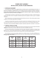
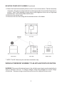
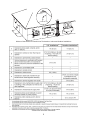
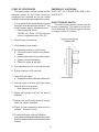
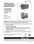
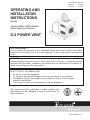
CATALOG NO. 6000.57E
Effective:
05-20-08
Replaces:
10-26-06
OPERATING AND
INSTALLATION
INSTRUCTIONS
Models
181/182, 260/261, 330/331, 400/401
Water Heaters and Boilers
D-2 POWER VENT
FOR YOUR SAFETY
Do not store or use gasoline or other flammable vapors and liquids or other combustible
materials in the vicinity of this or any other appliance. To do so may result in an explosion
or fire.
WARNING: Improper installation, adjustment, alteration, service or maintenance can cause
property damage, personal injury or loss of life. Refer to the user’s information manual
provided with this heater. Installation and service must be performed by a qualified installer, service agency or the gas supplier.
FOR YOUR SAFETY
WHAT TO DO IF YOU SMELL GAS:
· Do not try to light any appliance.
· Do not touch any electrical switch; do not use any phone in your building.
· Immediately call your gas supplier from a neighbor’s phone. Follow the gas
supplier’s instructions.
· If you cannot reach your gas supplier, call the fire department.
This manual should be maintained in legible condition and
kept adjacent to the appliance or kept in a safe place for
future reference.
P/N 241086 Rev. 6
POWER VENT ASSEMBLY
INSTALLATION, START-UP AND OPERATION
1. RECEIVING EQUIPMENT
On receipt of your equipment it is suggested that you visually check for external damage to the carton. If
the carton is damaged, it is suggested that a note be made on the Bill of Lading when signing for equipment.
Remove the complete assembly from the carton if it is damaged report the damage to the carrier immediately.
Be sure that you receive the number of packages indicated on the Bill of Lading. Claims for shortages and
damages must be filed with the carrier by consignee.
Purchased parts are subject to replacement only under the manufacturer's warranty. Debits for defective
replacement parts will not be accepted and defective parts will be replaced in kind only per our standard
warranties.
When ordering parts, you must specify Model and Serial Number of the unit. When ordering under warranty
conditions, you must also specify date of Installation.
Raypak recommends that this manual be reviewed thoroughly before installing the D-2 Power Vent. If there
are any questions which this manual does not answer, please contact your local Raypak Representative.
THIS MANUAL SHOULD BE MAINTAINED IN LEGIBLE CONDITION AND KEPT ADJACENT TO THE UNIT.
2. GENERAL SPECIFICATIONS
The D-2 Power Vent Assembly is tested and certified to the latest edition of the American National Standard
ANSI Z21.56. standard for pool heaters, Z21.10.3 for water heaters and Z21.13 for boilers.
The Power Vent Assembly is a fan assisted combustion system designed for application to Raypak Heater
Models 181-401. The unit, when installed as directed, is capable of operating in applications such as through the
wall venting and reduced horizontal and vertical vent pipe sizes in new and existing installations.
The D-2 Power Vent assembly includes a blower with a 120/240 volt 60 Hz 1.0/1.95A 3200 RPM motor, a
plenum complete with a draft proving switch and a motor relay. When provided for field mounting the assembly
is equipped with a wire harness.
MODEL
SIZE
MINIMUM
CONNECTION
DIAMETER
KIT
NUMBER
FACTORY
WIRED
182/181
4”
008757
120V
260/261
4”
008757
120V
330/331
4”
008758
120V
400/401
4”
008758
120V
2
3. INSTALLATION REQUIREMENTS
The equipment must be installed in accordance with local codes, or in the absence of local codes with the
latest edition of the National Fuel Gas Code, ANSI Z223.1, the National Electrical Code, ANSI/NFPA 70.
The equipment shall be installed in accordance with those installation regulations in force in the local area where
the installation is to be made. These shall be carefully followed in all cases. Authorities having jurisdiction shall
be consulted before installations are made.
MOUNTING POWER VENT ASSEMBLY
Follow these instructions if the PowerVent venting system was purchased as an option
assembly kit.
1. Remove existing pagoda top (outdoor units) or drafthood (indoor units). To remove the
pagoda top, push the four brackets inward and pull up the pagoda top. The pagoda may
then be discarded.
2. Unscrew the four screws holding the outer top using a phillips screw driver. Remove the
jacket top.
3. Replace the inner stack adapter. If the heater had a drafthood installed previously, remove the inner stack adapter and replace it with the PowerVent stack adapter. Otherwise,
install the PowerVent stack adapter.
4. Unscrew the access panel on the right side of the appliance. Set aside the screws with
the access panel.
5. Remove the knurled screw holding the front door and set it aside with the door.
6. Mount the jacket top above the unit. Note: Do not install at this point.
7. Mount the Power Vent on the outer top.
8. Route the conduit harness of the PowerVent thru the outer top hole, around the adapter
towards the back of the unit. Continue routing the harness thru the corner slot, which
leads to open area behind the access panel. Finally, route only the wire harness thru the
7/8” grommet hole located on the sway brace. Follow instructions on page 7 to wire the
PowerVent. Note: Newer units have a 7/8” grommet located on the rain shield, which
would eliminate routing the harness around the back corner.
9. Re-mount the jacket top to its original position and screw in the four screws holding it
down to the appliance.
10. If the appliance is a 181, 182, 330 or 331, remove the tabs underneath the power vent
using a 5/16” nut driver and relocate them closer to the center of the Power Vent as shown
below.
3
MOUNTING POWER VENT ASSEMBLY-(continued
11. Mount the PowerVent assembly bottom on the 6” vent as shown below. Twist the assembly
downward. Snap the mounting brackets into their appropriate slot to hold the Power Vent in
position. Note: While twisting you may notice some roughness, this is due to a tight seal
between the 6” vent and the Power Vent flue box.
12. Re-mount the access panel.
13. Re-mount the front door along with the knurled screw on the heater.
** NOTE: The 90° elbow may be used as a termination cap.
WIRING A POWERVENT ASSEMBLY TO AN APPLIANCE WITH IID IGNITION.
WARNING: Disconnect all electrical power to the unit before servicing to avoid potential shock
injury or damage to the unit. To change voltages, follow wiring diagram for correct voltage
connections. Improper wiring connections can burnout the relay and blower motor.
4
VENTING
The vent pipe must be the same size or larger than what is indicated. The D-2 Power Vent is
capable of 360-degree discharge rotation and operates with a positive vent static pressure and
with a vent gas temperature less than 400°F. The total length of horizontal run shall not
exceed an equivalent of 40 feet including termination cap. For all cases, each 90-degree
elbow reduces the maximum horizontal vent run by 10 feet and each 45-degree elbow in the vent
run reduces the maximum vent run by 5 feet. See the table below for maximum vent lengths using
90-degree and 45-degree elbows. The D-2 Power Vent uses positive pressure to push flue
gases through the vent pipe to the outside. The vent must be installed to prevent flue gas leakage. Care must be taken during assembly to insure that all joints are sealed properly and are
airtight.
The vent must be installed to prevent the potential accumulation of condensate in the vent
pipes. It is recommened that:
a) The vent be installed with a slight downward slope of not more than 1/4” per foot of
horizontal run to the vent terminal.
b) The vent be insulated through the length of horizontal run.
For appliances installed in extreme cold climate, it is recommended that:
a) The vent be installed with a slight upward slope of not more than 1/4” per foot of
horizontal run to the vent terminal. In this case, an approved condensate trap must
be installed per applicable codes.
b) The vent be insulated through the length of the horizontal run.
Reduced Maximum Equivalent Vent Run (feet)
90 degree elbows
45 degree elbows
Quantity
Maximum Length
Quantity
Maximum Length
1
30
1
35
2
20
2
30
3
10
3
25
5
Minimum Clearances from Vent/Air Inlet Terminations - Indoor and Outdoor Installations
Vent/Air Inlet Termination Clearances
6
The Raypak Power Vent operates with a positive vent static pressure and with a vent gas
temperature that avoids excessive condensate production in the vent and as such it is listed
as a CATEGORY III appliance.
Exception: When a Power Vent is connected to a vertical vent of sufficient height to generate
a negative draft in the system. Consult sizing guide or factory.
The D-2 Power Vent assembly is suitable for through the wall venting, and for connection
to smaller size vent pipes and breeching other than the standard atmospheric heater.
THROUGH THE WALL VENT
The D-2 Power Vent assembly includes a wire harness, shown below, which provides quick
connections with the respective controls in the heater control box. The harness is of sufficient
length to fit the appliance for which it is sized.
Reference the wiring diagram supplied with each appliance for actual connections.
7
182-260 H4/WH1 (ATMOSPHERIC)
8
181-261 H4/WH1 (Low NOx)
9
Dimensional Data
Model
A
B
C
D
181 18.13 12.38 7.88 4.25
182 18.13 12.38 7.88 4.25
260
261
18.13 12.38 7.88
18.13 12.38 7.88
4.25
4.25
330
331
17.50 15.75 7.63
17.50 15.75 7.63
6.00
6.00
400
401
17.50 15.75 7.63
17.50 15.75 7.63
6.00
6.00
SEQUENCE OF OPERATION
On call for heat, the D-2 Power Vent fan (and appliance pump) start. When the flow switch
circuits close, the ignition system consisting of an electronic spark module, pilot gas system and
flame sensor, are energized. When draft proving switch closes and all safety circuits are
proven, the automatic main gas valves will open and the heater will operate. When the
operating limit circuit is satisfied, the heater will shut down.
10
START UP PROCEDURES
EMERGENCY SHUTDOWN
The water system, the gas system and the SHUT OFF ALL POWER AND GAS, CALL
electrical system for the heater should be GAS UTILITY.
completed and checked as per the heater
installation manual and associated documents.
DRAFT PROVING SWITCH
1. Turn on power to the heater with the manual
The draft proving switch insures that the
main gas valve and pilot gas valve off. The
blower is operating. The switch is in the limit
electric power supply requirements are:
circuit and does not allow the ignition module
• Dual-voltage fan motor.
to operate unless it is closed.
120/240 volt 60Hz 1.0/1.95 Amp fan
motor for appliance sizes 181-401.
2. Check power connections.
3. Close heater power switch.
4. Set operating control to call for heat.
a. Fan motor starts, draft proving switch
closes.
b. Heater pump starts, flow switch closes.
c. Ignition module energized.
d. Check for spark at gas pilot.
5. Turn operating control to end call for heat.
6. Wait a minimum of 60 seconds.
7. Open pilot gas valve.
a. Repeat procedure outlined in #4 above.
8. After pilot gas is proven and main safety
shut-off valve is energized.
- Main burners will ignite.
9. Heater will operate until call for heat is
satisfied.
11.Restart unit and visually check all components for proper operation.
12.Check all vent connections and joints for
leakage. Correct if found.
13. To restart unit after a failure, follow the
procedures outlined above and other subsequent or related sections outlined in the heater
manual.
11
ILLUSTRATED PARTS LIST
4
9
10
5
11
1
6
3
7
2
15
12
13
14
8
12
www.raypak.com
Raypak, Inc., 2151 Eastman Avenue, Oxnard, CA 93030 (805) 278-5300 FAX (800) 872-9725
Litho in U.S.A.