1
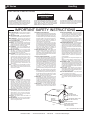
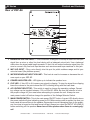
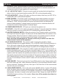
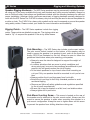
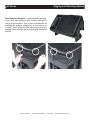
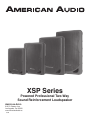
XSP Series
Powered Professional Two-Way
Sound Reinforcement Loudspeaker
American Audio
6122 S. Eastern Ave.
Los Angeles, Ca. 90040
www.AmericanAudio.us
5/09
XSP Series
Contents
CUSTOMER SUPPORT..........................................................................................................................2
UNPACKING.............................................................................................................................2
HANDLING PRECAUTIONS...................................................................................................................3
FEATURES...........................................................................................................................................4
PRODUCT REGISTRATION....................................................................................................................5
front panel FEATURES....................................................................................................................6
XSP-8P REAR PANEL controls.......................................................................................................7
XSP-10P REAR PANEL controls......................................................................................................9
XSP-12P REAR PANEL controls....................................................................................................11
XSP-15P REAR PANEL controls....................................................................................................13
RIGGING AND MOUNTING.................................................................................................................17
Available ACCESSORIES.................................................................................................................19
Warranty.......................................................................................................................................20
SPECIFICATIONS.................................................................................................................................21
XSP Series
Introduction
Introduction: Congratulations and thank you for purchasing the American Audio® XSP Series professional sound reinforcement loudspeaker. This loudspeaker is a representation of American Audio’s
continuing commitment to produce the best and highest quality audio products possible at an affordable price. The XSP Series is a wo-way active loudspeaker encased in a light weight cabinet. This
speaker has been designed to be used as both a portable and a permanently installed unit. The speaker
includes a poll mount slot and rubber feet on the bottom of the unit for portable applications and also
includes rigging points on the top, bottom, and rear of the unit for permanent and flight installations.
Please read and understand this manual completely before attempting to operate your new speaker
system. This booklet contains important information concerning the proper and safe operation of your
new speaker.
Customer Support: American Audio® provides a toll free customer support line, to provide set up help
and answer any question should you encounter problems during your initial set up or operation. You
may also visit us on the web at www.americandj.com for any comments or suggestions. Service Hours
are Monday through Friday 9:00 a.m. to 5:30 p.m. Pacific Standard Time.
Voice:
(800) 322-6337
Fax: (323) 582-2610
E-mail: [email protected]
Caution! There are no user serviceable parts inside this speaker. Do not attempt any repairs, without
being instructed to do so by an authorized American Audio technician. Doing so will void your manufactures warranty. In the unlikely event your speaker may require service, please contact American Audio®.
XSP Series
Unpacking
Every XSP Series has been thoroughly tested and has been shipped in perfect operating condition.
Carefully check the shipping carton for damage that may have occurred during shipping. If the carton appears to be damaged carefully inspect your units for any damage and be sure all accessories
necessary to operate the system have arrived intact. In the event damage has been found or parts are
missing, please contact our toll free customer support number for further instructions. Please do not
return the speaker to your dealer without first contacting customer support.
©American
Audio® - www.AmericanAudio.us - XSP Series - Instruction Manual Page 2
XSP Series
Handling
ELECTRICAL PRECAUTIONS
CAUTION
RISK OF ELECTRIC SHOCK
DO NOT OPEN
The lightning flash with arrowhead symbol, within an
equilateral triangle, is intended to alert the user to the
presence of uninsulated "dangerous voltage" within the
product's enclosure that may be of sufficient magnitude
to constitute a risk of electric shock to persons.
CAUTION: TO REDUCE THE RISK OF ELECTRIC
SHOCK, DO NOT REMOVE THE COVER (OR BACK).
THERE ARE NO USER SERVICEABLE PARTS
INSIDE REFER SERVICE TO YOUR AUTHORIZED
AMERICAN AUDIO® SERVICE TECHNICIAN.
The exclamation point within an equilateral triangle is
intended to alert the user to the presence of important
operating and maintenance (servicing) instructions in
the literature accompanying the appliance.
IMPORTANT SAFETY INSTRUCTIONS
reAd inSTrucTionS — All the safety and operating
instructions should be read before the product is
operated.
reTAin inSTrucTionS — The safety and operating
instructions should be retained for future reference.
Heed WArninGS — All warnings on the product and
in the operating instructions should be adhered to.
FoLLoW inSTrucTionS — All operating and use
instructions should be followed.
cLeAninG — The product should be cleaned only with
a polishing cloth or a soft dry cloth. Never clean with
furniture wax, benzine, insecticides or other volatile
liquids since they may corrode the cabinet.
ATTAcHmenTS — Do not use attachments not
recommended by the product manufacturer as they
may cause hazards.
WATer And moiSTure — Do not use this product
near water — for example, near a bathtub, wash
bowl, kitchen sink, or laundry tub; in a wet basement;
or near a swimming pool; and the like.
AcceSSorieS — Do not place this product on an
unstable cart, stand, tripod, bracket, or table. The
product may fall, causing serious injury to a child or
adult, and serious damage to the product. Use only
with a cart, stand, tripod, bracket, or table
recommended by the manufacturer, or sold with
the product. Any mounting of the product should
follow the manufacturer’s instructions, and should
use a mounting accessory recommended by the
manufacturer.
cArT — A product and cart combination should be
moved with care. Quick stops, excessive force, and
uneven surfaces may cause the product and cart
combination to overturn.
VenTiLATion — Slots and openings in the cabinet are
provided for ventilation and to ensure reliable
operation of the product and to protect it from
overheating, and these openings must not be
blocked or covered. The openings should never be
blocked by placing the product on a bed, sofa, rug,
or other similar surface. This product should not be
placed in a built-in installation such as a bookcase or
rack unless proper ventilation is provided or the
manufacturer’s instructions have been adhered to.
PoWer SourceS —This product should be operated
only from the type of power source indicated on the
marking label. If you are not sure of the type of
power supply to your home, consult your product
dealer or local power company.
LocATion – The appliance should be installed in a
stable location.
nonuSe PeriodS – The power cord of the appliance
should be unplugged from the outlet when left unused for a long period of time.
GroundinG or PoLAriZATion
•
If this product is equipped with a polarized alternating
current line plug (a plug having one blade wider than
the other), it will fit into the outlet only one way. This
is a safety feature. If you are unable to insert the plug
fully into the outlet, try reversing the plug. If the plug
should still fail to fit, contact your electrician to
replace your obsolete outlet. Do not defeat the
safety purpose of the polarized plug.
•
If this product is equipped with a three-wire
grounding type plug, a plug having a third (grounding)
pin, it will only fit into a grounding type power outlet.
This is a safety feature. If you are unable to insert the
plug into the outlet, contact your electrician to
replace your obsolete outlet. Do not defeat the
safety purpose of the grounding type plug.
PoWer-cord ProTecTion - Power-supply cords
should be routed so that they are not likely to be
walked on or pinched by items placed upon or
against them, paying particular attention to cords at
plugs, convenience receptacles, and the point where
they exit from the product.
ouTdoor AnTennA GroundinG — If an outside
antenna or cable system is connected to the product,
be sure the antenna or cable system is grounded so
as to provide some protection against voltage surges
and built-up static charges. Article 810 of the National
Electrical Code, ANSI/NFPA 70, provides information
with regard to proper grounding of the mast and
supporting structure, grounding of the lead-in wire
to an antenna discharge unit, size of grounding
conductors, location of antenna-discharge unit,
connection to grounding electrodes, and
requirements for the grounding electrode. See Figure
A.
LiGHTninG — For added protection for this product
during a lightning storm, or when it is left unattended
and unused for long periods of time, unplug it from
the wall outlet and disconnect the antenna or cable
system. This will prevent damage to the product
due to lightning and power-line surges.
PoWer LineS — An outside antenna system should
not be located in the vicinity of overhead power lines
or other electric light or power circuits, or where it
can fall into such power lines or circuits. When
installing an outside antenna system, extreme care
should be taken to keep from touching such power
lines or circuits as contact with them might be fatal.
oVerLoAdinG — Do not overload wall outlets,
extension cords, or integral convenience receptacles
as this can result in a risk of fire or electric shock.
oBJecT And LiQuid enTrY - Never push objects of
any kind into this product through openings as they
may touch dangerous voltage points or short-out
parts that could result in a fire or electric shock.
Never spill liquid of any kind on the product.
SerVicinG — Do not attempt to service this product
yourself as opening or removing covers may expose
you to dangerous voltage or other hazards. Refer all
servicing to qualified service personnel.
dAmAGe reQuirinG SerVice - Unplug this product
from the wall outlet and refer servicing to qualified
service personnel under the following conditions:
•
When the power-supply cord or plug is damaged.
•
If liquid has been spilled, or objects have fallen into
the product.
•
If the product has been exposed to rain or water.
•
If the product does not operate normally by following
the operating instructions. Adjust only those controls
that are covered by the operating instructions as an
improper adjustment of other controls may result in
damage and will often require extensive work by a
qualified technician to restore the product to its
normal operation.
•
If the product has been dropped or damaged in any
way.
•
When the product exhibits a distinct change in
performance — this indicates a need for service.
rePLAcemenT PArTS -- W hen replacement parts
are required, be sure the service technician has used
replacement parts specified by the manufacturer or
have the same characteristics as the original part.
Unauthorized substitutions may result in fire, electric
shock, or other hazards.
SAFeTY cHecK - Upon completion of any service or
repairs to this product, ask the service technician to
perform safety checks to determine that the product
is in proper operating condition.
WALL or ceiLinG mounTinG — The product should
not be mounted to a wall or ceiling.
HeAT — The product should be situated away from heat
sources such as radiators, heat registers, stoves, or
other products (including amplifiers) that produce
heat.
ANTENNA
LEAD IN
WIRE
GROUND
CLAMP
ANTENNA
DISCHARGE UNIT
(NEC SECTION 810-20)
ELECTRIC
SERVICE
EQUIPMENT
Fig. A
GROUNDING CONDUCTORS
(NEC SECTION 810-21)
GROUND CLAMPS
POWER SERVICE GROUNDING
ELECTRODE SYSTEM
(NEC ART 250, PART H)
NEC — NATIONAL ELECTRICAL CODE
©American
Audio® - www.AmericanAudio.us - XSP Series - Instruction Manual Page 3
XSP Series
Safety Precautions
XSP Series loudspeaker can easily reproduce sound pressure levels (SPL) sufficient enough to
cause sever and permanent hearing damage. A great degree of care should be taken to protect your
ears to prolong exposure to SPL in excess of 85dB.
• For adult use only - Keep out of the reach of children.
• Be sure all power is turned off before making speaker connections
• Do not remove the speaker cover or grill under any conditions
•Always use a power cord that meets the manufactures exact power specifications
•Disconnect from main power before making any type of connection
•To reduce the risk of electrical shock or fire, do not expose this unit rain or moisture
•This speaker is intended for indoor use only, use of this product outdoors voids all warranties.
•Always mount this speaker in safe and stable matter.
•Be sure to tighten the pole mount screw when using a pole stand.
• Make sure your speaker stand has proper footing. Use sand bags when needed.
•Power Cord Protection - Power supply cords should be routed so that they are not likely to be walked on or pinched by items placed upon or against them, paying particular attention to cords
at plugs, convenience receptacles, and the point where they exit from the speaker.
•Heat -The speaker should be situated away from heat sources such as radiators, heat registers, stoves, or other mixers (including amplifiers) that produce heat
•Be sure to save the packing carton in the event the unit needs to be returned for service
• Read all documentation before attempting to operate your new mixer. Please save all your docu-
mentation for future reference
• Do not spill water or other liquids in to or on to your speaker
•Be sure that the local power outlet matches that of the required voltage for your speaker.
• Do not attempt to operate this speaker if the power cord has been frayed or broken. Please route
your power cord out of the way of foot traffic
• Always have the gain controls set to their lowest level during initial power-up to prevent speaker damage
• Servicing - The user should not attempt to service the speaker beyond that described in this
manual. All other servicing should be referred to qualified service personnel. The speaker should
only be serviced by qualified personal when;
A.Objects have fallen, or liquid has been spilled into the speaker
B. The speaker has been exposed to rain or water
C.The speaker does not appear to operate normally or exhibits a change in performance
D. The terminal/cross-over plate has been damaged
©American
Audio® - www.AmericanAudio.us - XSP Series - Instruction Manual Page 4
XSP Series
XSP-8P:
• 100 Watt Built-In Bi-Amplifier
• Heavy Duty Nylon Fiber Cabinet
• Built in XLR Mic and Line Level Inputs
• Attached heavy Duty Rubber Feet
• Built-in Pole Mount
• Three Built-in Rigging Points
XSP-10P, 12P, & 15P:
• 200 Watt Built-In Bi-Amplifier (XSP-10P)
• 300 Watt Built-In Bi-Amplifier (XSP-12P)
• 400 Watt Built-In Bi-Amplifier (XSP-15P)
• Neodymium Woofers (12P & 15P)
• Clip and Power LEDs
Main Features
•
•
•
•
•
•
•
•
•
•
•
•
•
Built-in Heavy Duty Carrying Handle
Seperate Microphone Volume Controls
XLR and RCA Balanced Inputs
Electronic Crossover
1/4” and XLR Line Outputs
Bass, Treble, Level and Volume Controls
Built in XLR & 1/4” Mic and Line Level Inputs
Built In RCA Inputs
Heavy Duty Nylon Fiber Cabinet
Built in XLR Mic and Line Level Inputs
Attached heavy Duty Rubber Feet
Built-in Pole Mount
Three Built-in Rigging Points
XSP Series
Registration
The XSP Series speakers carry a one year (365 days) limited warranty. Please fill out the enclosed
warranty card to validate your purchase. All returned service items whether under warranty or not,
must be freight pre-paid and accompany a return authorization (R.A.) number. The R.A. number must
be clearly written on the outside of the return package. A brief description of the problem as well as
the R.A. number must also be written down on a piece of paper and included in the shipping container. If the unit is under warranty, you must provide a copy of your proof of purchase invoice. You
may obtain a R.A. number by contacting customer support at (800) 322-6337. All packages returned
to the service department not displaying a R.A. number on the outside of the shipping package will
be returned to the shipper unopened.
The serial and model number for this unit is located on the rear panel Please write down the numbers here and retain them for future reference.
Model No.________________________________
Date Purchased___________________________
Serial No.________________________________
Dealer Name______________________________
©American
Audio® - www.AmericanAudio.us - XSP Series - Instruction Manual Page 5
XSP Series
Controls and Features
5
1
6
2
7
3
MASTER
THROUGH
4
6
8
3
1. High Frequency transducer – This unit is used to reproduce the high frequency
response.
2. Woofer – The high-powered woofer is used to reproduce the midrange and low frequencies.
3. Rubber Foot – The speaker includes heavy-duty rubber feet on the bottom of the unit.
These feet are used to secure a speaker to another when stacking. They are also used to
secure the speaker to the ground to prevent it from shifting during heavy bass reproduction.
4. Pole Mount Socket – This socket is designed to fit a standard speaker pole mount or tripod such as the American Audio® SPS-1B speaker stand.
5. Stacking notches – These notches are designed to line up with the rubber feet of another
XSP Series and are used to support another speaker when they are stacked together.
6. Rigging Points – The XSP Series speaker has three rigging points. These points are to be
used to “fly” or suspend the speaker in the air by some means. Be sure to follow the “flying”
outlines on page 17.
7.Transport Handle – The XSP Series speakers come with built-in heavy-duty transportation handle. Use this handle for secure and easy transportation.
8. Pole Mount Locking Bolt – This pin is used to secure the speaker in place when mounting the speaker in a pole mount configuration. Always be sure to tighten down on the locking
bolt to prevent the speaker from shifting during use.
©American
Audio® - www.AmericanAudio.us - XSP Series - Instruction Manual Page 6
XSP Series
Controls and Features
Rear of XSP-8A
1
LINE OUT
LINE IN
2
MIC
LEVEL
10
110V
INPUT
200 WATTS
220V
3
4
5
6
7
8
9
1.Balanced XLR Line Input – This connection is designed to accept a balanced line input
signal from a mixer or other line level device with a balanced output jack. Use a balanced
cable when the signal cable length exceeds 15 feet, this will reduce excessive signal loss. Be
sure to connect only line level input devices such as mixers and tape machines to this jack.
2. Mic XLR Input - Plug a mic directly into this port for public address usage and let your
voice be heard. (No phantom power)
3. Microphone/line input Volume – This knob is used to increase or decrease the volume ouput on your XSP-8P.
4. Power indicator led - LED lights up to indicate the speaker is on.
5. Clip Led - If this LED is lit it means your signal is clipping. To stop the signal from clipping
lower the volume to the point where the LED is blinking along with the bass beat.
6. AC VOLTAGE SELECTOR - This switch is used to change the operating voltage. Operating voltage can be toggled between 115v or 230v/50~60Hz. Be sure the selector is set to the proper voltage for your area before attempting to operate the unit. Always be sure main power is shut off before change the position of the Voltage Selector Switch.
7. Main Power Switch – This is the main power ON/OFF button. A green LED directly above
the power switch will glow indicating power is ON. Before main power is applied, be sure you
have made all connections to the speaker. Remember to avoid damaging pops to the speakers, the mixer is turned on first and turned off last. Always turn down the INPUT VOLUME (3)
before switching off the speaker. Never turn off the speaker when there is a running signal!
©American
Audio® - www.AmericanAudio.us - XSP Series - Instruction Manual Page 7
XSP Series
Controls and Features
8. Main Power Inlet – This connector is used to supply main power to the unit via the included detachable power cord. The power connection uses an I.E.C. type connector, use
only a power cord that matches this type of connection. Be sure to only connect this unit to
a power outlet that matches the printed power label on the unit. Never use a power when the
ground prong has been removed or broken off. The ground prong is used to reduce the risk
of electrical shock in case of an electrical short. This cord is designed to fit in one direction
only. Do not attempt to force a cord if it does not fit, be sure the cord is being inserted properly.
9. Fuse Holder – This housing stores the 2 amp GMA protective fuse. Always replace with
the exact same type fuse, unless otherwise instructed, by an authorized American Audio®
service technician. Replacing with any other type of fuse than that of the recommended fuse
will void your unit warranty.
10. XLR LINE output – Using a XLR cable, use this port to daisy chain from your XSP-8P to
another XSP-8P or other powered speaker.
©American
Audio® - www.AmericanAudio.us - XSP Series - Instruction Manual Page 8
XSP Series
Rear of XSP-10A
XSP-10A - Controls and Features
1
2
3
4
5
6
7
8
9
10
11
12
13
14
15
16
17
1. Mic XLR Input - Plug a mic directly into this port for public address usage and let your
voice be heard. (No phantom power)
2. Microphone input Volume – This knob is used to increase or decrease the volume
ouput on your XSP-10P.
3. 1/4” MIC Input – Plug a mic directly into this port.
4. Line level input volume – This knob is used to regulate the output signal of the line level
source connected to the Line Level Inputs (5 & 7).
5.Balanced RCA Line Input – This connection is designed to accept a balanced line input
signal from a mixer or other line level device with a balanced output jack. Use a balanced
cable when the signal cable length exceeds 15 feet, this will reduce excessive signal loss. Be
sure to connect only line level input devices such as mixers and tape machines to this jack.
6. output volume – This knob is used to regulate the output signal being sent to another
XSP-8A or other powered speaker.
7.Balanced XLR Line Input – This connection is designed to accept a balanced line input
signal from a mixer or other line level device with a balanced output jack. Use a balanced
cable when the signal cable length exceeds 15 feet, this will reduce excessive signal loss.
8. Treble control – This knob is used to regulate the amount treble applied to the output signal. The maximum amount of treble gain is +12dB and the maximum amount of treble decrease is -12dB. Turning the knob in a counter-clockwise direction will decrease the amount of treble applied to a channel signal, turning the knob in a clockwise direction will increase the amount of treble applied to a channel signal.
©American
Audio® - www.AmericanAudio.us - XSP Series - Instruction Manual Page 9
XSP Series
Controls and Features
9. 1/4” Line Output Jack – This jack is used to send the incoming line level signal from either of the Line Level Inputs Jacks to another XSP-10P or other powered speaker.
10. Bass Control – This knob is used to regulate the amount bass applied to the output signal. The maximum amount of bass gain is +12dB and the maximum amount of bass decrease is -12dB. Turning the knob in a counter-clockwise direction will decrease the amount of bass applied to a channel signal, turning the knob in a clockwise direction will increase the amount of bass applied to a channel signal.
11. XLR LINE output – Using a XLR cable, use this port to daisy chain from your XSP-10P to another XSP-10P or other powered speaker.
12. Power indicator led - LED lights up to indicate the speaker is on.
13. Clip Led - If this LED is lit it means your signal is clipping. To stop the signal from clipping
lower the volume to the point where the LED is blinking along with the bass beat.
14. AC VOLTAGE SELECTOR - This switch is used to change the operating voltage. Operating voltage can be toggled between 115v or 230v/50~60Hz. Be sure the selector is set to the proper voltage for your area before attempting to operate the unit. Always be sure main power is shut off before change the position of the Voltage Selector Switch.
15.Main Power Inlet – This connector is used to supply main power to the unit via the included detachable power cord. The power connection uses an I.E.C. type connector, use
only a power cord that matches this type of connection. Be sure to only connect this unit to
a power outlet that matches the printed power label on the unit. Never use a power when the
ground prong has been removed or broken off. The ground prong is used to reduce the risk
of electrical shock in case of an electrical short. This cord is designed to fit in one direction
only. Do not attempt to force a cord if it does not fit, be sure the cord is being inserted properly.
16.Fuse Holder – This housing stores the 3.15 amp GMA protective fuse. Always replace
with the exact same type fuse, unless otherwise instructed, by an authorized American
Audio® service technician. Replacing with any other type of fuse than that of the recommended fuse will void your unit warranty.
17. Main Power Switch – This is the main power ON/OFF button. A green LED directly above
the power switch will glow indicating power is ON. Before main power is applied, be sure you
have made all connections to the speaker. Remember to avoid damaging pops to the speakers, the mixer is turned on first and turned off last. Always turn down the INPUT VOLUME (3)
before switching off the speaker. Never turn off the speaker when there is a running signal!
©American
Audio® - www.AmericanAudio.us - XSP Series - Instruction Manual Page 10
XSP Series
Controls and Features
1
Rear of XSP-12A
2
3
4
5
6
7
8
9
10
11
12
13
14
15
16
17
1. Mic XLR Input - Plug a mic directly into this port for public address usage and let your
voice be heard. (No phantom power)
2. Microphone input Volume – This knob is used to increase or decrease the volume
ouput on your XSP-12P.
3. 1/4” MIC Input – Plug a mic directly into this port.
4. Line level input volume – This knob is used to regulate the output signal of the line level
source connected to the Line Level Inputs (5 & 7).
5.Balanced RCA Line Input – This connection is designed to accept a balanced line input
signal from a mixer or other line level device with a balanced output jack. Use a balanced
cable when the signal cable length exceeds 15 feet, this will reduce excessive signal loss. Be
sure to connect only line level input devices such as mixers and tape machines to this jack.
6. output volume – This knob is used to regulate the output signal being sent to another
XSP-8A or other powered speaker.
7.Balanced XLR Line Input – This connection is designed to accept a balanced line input
signal from a mixer or other line level device with a balanced output jack. Use a balanced
cable when the signal cable length exceeds 15 feet, this will reduce excessive signal loss.
8. Treble control – This knob is used to regulate the amount treble applied to the output signal. The maximum amount of treble gain is +12dB and the maximum amount of treble decrease is -12dB. Turning the knob in a counter-clockwise direction will decrease the amount of treble applied to a channel signal, turning the knob in a clockwise direction will ©American
Audio® - www.AmericanAudio.us - XSP Series - Instruction Manual Page 11
XSP Series
Controls and Features
increase the amount of treble applied to a channel signal.
9. 1/4” Line Output – This is used to send the incoming line level signal from either of the Line Level Inputs Jacks to another XSP-12P or other powered speaker.
10. XLR LINE output – Using a XLR cable, use this port to daisy chain from your XSP-12P to another XSP-12P or other powered speaker.
11.Bass Control – This knob is used to regulate the amount bass applied to the output signal. The maximum amount of bass gain is +12dB and the maximum amount of bass decrease is -12dB. Turning the knob in a counter-clockwise direction will decrease the amount of bass applied to a channel signal, turning the knob in a clockwise direction will increase the amount of bass applied to a channel signal.
12. Power indicator led - LED lights up to indicate the speaker is on.
13. Clip Led - If this LED is lit it means your signal is clipping. To stop the signal from clipping
lower the volume to the point where the LED is blinking along with the bass beat.
14. AC VOLTAGE SELECTOR - This switch is used to change the operating voltage. Operating voltage can be toggled between 115v or 230v/50~60Hz. Be sure the selector is set to the proper voltage for your area before attempting to operate the unit. Always be sure main power is shut off before change the position of the Voltage Selector Switch.
15.Main Power Inlet – This connector is used to supply main power to the unit via the included detachable power cord. The power connection uses an I.E.C. type connector, use
only a power cord that matches this type of connection. Be sure to only connect this unit to
a power outlet that matches the printed power label on the unit. Never use a power when
the ground prong has been removed or broken off. The ground prong is used to reduce the
risk of electrical shock in case of an electrical short. This cord is designed to fit in one direction only. Do not attempt to force a cord if it does not fit, be sure the cord is being inserted
properly.
16.Fuse Holder – This housing stores the 5 amp GMA protective fuse. Always replace with
the exact same type fuse, unless otherwise instructed, by an authorized American Audio®
service technician. Replacing with any other type of fuse than that of the recommended
fuse will void your unit warranty.
17. Main Power Switch – This is the main power ON/OFF button. A green LED directly
above the power switch will glow indicating power is ON. Before main power is applied, be
sure you have made all connections to the speaker. Remember to avoid damaging pops to
the speakers, the mixer is turned on first and turned off last. Always turn down the INPUT
VOLUME (3) before switching off the speaker. Never turn off the speaker when there is a
running signal!
©American
Audio® - www.AmericanAudio.us - XSP Series - Instruction Manual Page 12
XSP Series
Controls and Features
Rear of XSP-15A
MASTER
THROUGH
1
2
3
4
5
6
7
8
9
10
11
12
13
14
15
16
17
18
19
20
21
1. Mic 1 XLR Input - Plug a mic directly into this port for public address usage and let your
voice be heard. (No phantom power)
2. 1/4” MIC 1 Input – Plug a mic directly into this port.
3. Microphone 1 input Volume – This knob is used to increase or decrease the volume
ouput on your XSP-15P.
4. Mic 2 XLR Input - Plug a mic directly into this port for public address usage and let your
voice be heard. (No phantom power)
5. Microphone 2 input Volume – This knob is used to increase or decrease the volume
ouput on your XSP-15P.
6. 1/4” MIC 2 Input – Plug a mic directly into this port.
7. Line level input volume – This knob is used to regulate the output signal of the line level
source connected to the Line Level Inputs (8 & 10).
8.Balanced RCA Line Input – This connection is designed to accept a balanced line input
signal from a mixer or other line level device with a balanced output jack. Use a balanced
cable when the signal cable length exceeds 15 feet, this will reduce excessive signal loss. Be
sure to connect only line level input devices such as mixers and tape machines to this jack.
9. output volume – This knob is used to regulate the output signal being sent to another
XSP-15P or other powered speaker.
10.Balanced XLR Line Input – This connection is designed to accept a balanced line input
signal from a mixer or other line level device with a balanced output jack. Use a balanced
cable when the signal cable length exceeds 15 feet, this will reduce excessive signal loss.
11.Treble control – This knob is used to regulate the amount treble applied to the output signal. The maximum amount of treble gain is +12dB and the maximum amount of treble ©American
Audio® - www.AmericanAudio.us - XSP Series - Instruction Manual Page 13
XSP Series
Controls and Features
decrease is -12dB. Turning the knob in a counter-clockwise direction will decrease the amount of treble applied to a channel signal, turning the knob in a clockwise direction will increase the amount of treble applied to a channel signal.
12. 1/4” Line Output Jack – This jack is used to send the incoming line level signal from either of the Line Level Inputs Jacks to another XSP-15P or other powered speaker.
13. XLR LINE output – Using a XLR cable, use this port to daisy chain from your XSP-15P to another XSP-15P or other powered speaker.
14.Bass Control – This knob is used to regulate the amount bass applied to the output signal. The maximum amount of bass gain is +12dB and the maximum amount of bass decrease is -12dB. Turning the knob in a counter-clockwise direction will decrease the amount of bass applied to a channel signal, turning the knob in a clockwise direction will increase the amount of bass applied to a channel signal.
15. Power indicator led - LED lights up to indicate the speaker is on.
16. Clip Led - If this LED is lit it means your signal is clipping. To stop the signal from clipping
lower the volume to the point where the LED is blinking along with the bass beat.
17. MASTER/THROUGH SWITCH - When the switch is in the Through position only the line level inputs will transmit a signal. The Mic Inputs will be disabled when the switch is in the Through position. When the switch is in Master position, the speakers output is effected by the line level control, mic volume control, and master volume control.
When switching between Master & Through, make sure you either turn down the volume levels or switch off the speakers.
18. AC VOLTAGE SELECTOR - This switch is used to change the operating voltage. Operating voltage can be toggled between 115v or 230v/50~60Hz. Be sure the selector is set to the proper voltage for your area before attempting to operate the unit. Always be sure main power is shut off before change the position of the Voltage Selector Switch.
19.Main Power Inlet – This connector is used to supply main power to the unit via the included detachable power cord. The power connection uses an I.E.C. type connector, use
only a power cord that matches this type of connection. Be sure to only connect this unit to
a power outlet that matches the printed power label on the unit. Never use a power when
the ground prong has been removed or broken off. The ground prong is used to reduce the
risk of electrical shock in case of an electrical short. This cord is designed to fit in one direction only. Do not attempt to force a cord if it does not fit, be sure the cord is being inserted
properly.
20.Fuse Holder – This housing stores the 5 amp GMA protective fuse. Always replace with
the exact same type fuse, unless otherwise instructed, by an authorized American Audio®
service technician. Replacing with any other type of fuse than that of the recommended
fuse will void your unit warranty.
21. Main Power Switch – This is the main power ON/OFF button. A green LED directly
above the power switch will glow indicating power is ON. Before main power is applied, be
sure you have made all connections to the speaker. Remember to avoid damaging pops to
the speakers, the mixer is turned on first and turned off last. Always turn down the INPUT
VOLUME (3) before switching off the speaker. Never turn off the speaker when there is a
running signal!
©American
Audio® - www.AmericanAudio.us - XSP Series - Instruction Manual Page 14
XSP Series
Typical Speaker Set-Up
Typical XSP Series Output Set-Up
AUX 4
AUX / IN
MODEL NO.: Q-3433 MKII
POWER SOURCE:
115/230V~ 50/60Hz 20W
MADE IN CHINA
MIN
MAX
TRIM OUTPUT
XLR-XLR Balanced Cables
Connections are the same for 12P & 15P
Speakers
XSP 10P
©American
XSP 10P
Audio® - www.AmericanAudio.us - XSP Series - Instruction Manual Page 15
XSP Series
Looping Speakers
XSP Speaker Looping
From Mixer
MASTER
MASTER
THROUGH
THROUGH
To Next XSP Speaker (If Applicable)
©American
Audio® - www.AmericanAudio.us - XSP Series - Instruction Manual Page 16
Rigging and Mounting Options
XSP Series
Speaker Rigging Hardware – The XSP Series speakers may be permanently installed or mount-
ed using any of the many available third party wall brackets and ceiling mounts available. Always be
sure to follow all safety instructions and guidelines included with the mounting hardware for safe and
proper installation. American Audio® carries an assortment of rigging hardware specially designed to
work with the XSP Series.The Z-APX/B is a heavy-duty bolt and may be used to secure the speaker to
a cable or chain. The Z-APX/H is a heavy-duty eyebolt and is used to suspend or secure the speaker
using safety cables. Please contact your dealer for more information and availability.
Rigging Points – The XSP Series speakers include four rigging
points. These points are detailed on page six. The rigging points are
used to “fly” or suspend the speaker in the air by some means.
Pole Mounting – The XSP Series also include a pole mount option.
The pole mount socket located on the bottom of the speaker may be
used to secure the speaker to a speaker tri-pod, such as the American
Audio® SPS-1B as illustrated on the left. Always be sure to follow the
guidelines listed below when pole mounting your speaker;
• Always be sure the stand is designed to support the weight of
the speaker
• In outdoor situations that are prone to windy conditions and
strong wind gust, be sure to use sandbags as additional tri-pod
support, this will greatly reduce the risk of tipping
• Do not stack speakers on top of each other when mounting on
a tri-pod. Only one speaker should be mounted to a tri-pod at one
time.
• Always position the tri-pod legs away from foot traffic
• Extend the tri-pod legs to their fully extended position to avoid
accidental tipping
• Observe and follow all safety guidelines and regulations specified
by the tri-pod’s manufacturer
• Be sure the tri-pod is situated on a flat, level, and stable surface
• Always tighten all tri-pod locks
Pole Mount Locking Screw – This screw is located on the rear of
the speaker and is attached to the pole mount socket. Always use this
screw to secure the speaker in place when mounting this speaker in a
pole mount configuration. Always be sure to tighten down on this screw
to prevent the speaker from shifting directions during use.
©American
Audio® - www.AmericanAudio.us - XSP Series - Instruction Manual Page 17
XSP Series
Rigging and Mounting Options
Floor Monitor Brackets - These brackets are helpful for DJ’s and bands to help moniter their sound
during a performance. This is also an alternative to
standing the speaker straight up or mounting it on
a stand. These brackets slide into each end of the
speaker. Each speaker has its own special sized floor
bracket.
©American
Audio® - www.AmericanAudio.us - XSP Series - Instruction Manual Page 18
XSP Series
Available Accessories
APX-B - Speaker Carry Case - A rugged gig bag with
rollers, an adjustable pull out handle, and a heavy duty
zipper. Designed to protect your speaker from damage
and the environment during transportation and storage.
Z-APX/B 7 Z-APX/H - Speaker Rigging Hardware
- American Audio® carries an assortment of rigging
hardware specially designed to work with the XSP
Series.™The Z-APX/B is a heavy-duty bolt and may be
used to secure the speaker to a cable or chain. The ZAPX/H is a heavy-duty eyebolt and is used to suspend
or secure the speaker using safety cables.
SPS-1B - Speaker Stands - American Audio® carries the SPS-1B speaker stand, which can be used to raise the speakers during use The SPS-1B
is a sturdy aluminum tri-pod and includes a mounting socket bracket for
added security. The SPS-1B can raise the speaker to a maximum height
of six feet and has a maximum weight capacity of 80 pounds. SPS-1B;
weight = 6lbs, pipe diameter - 1 3/8”
PXI BR15 - Wall Mounting Brackets - This bracket is
helpful for mounting the XSP Series speakers to a trussing setup or a wall. This is also an alternative to mounting it on a stand. These brackets bolt into the top and
bottom of the speaker. Each speaker has its own special
sized bracket.
©American
Audio® - www.AmericanAudio.us - XSP Series - Instruction Manual Page 19
XSP Series
1-YEAR LIMITED WARRANTY
Warranty
A.
American Audio® hereby warrants, to the original purchaser, American Audio® products to be free of manufacturing defects in material and workmanship for a period of 1 Year (365 days) from the date of purchase. This warranty shall be valid only if the product is purchased within the United States of America, including possessions and territories. It is the owner’s responsibility to establish the date and place of purchase by acceptable evidence, at the time service is sought.
B.
For warranty service, send the product only to the American Audio® factory. All shipping charges
must be pre-paid. If the requested repairs or service (including parts replacement) are within the terms of this warranty, American Audio® will pay return shipping charges only to a designated
point within the United States. If the entire instrument is sent, it must be shipped in its original
package. No accessories should be shipped with the product. If any accessories are shipped
with the product, American Audio® shall have no liability whatsoever for loss of or damage to
any such accessories, nor for the safe return thereof.
C.
This warranty is void if the serial number has been altered or removed; if the product is modified
in any manner which American Audio® concludes, after inspection, affects the reliability of the
product; if the product has been repaired or serviced by anyone other than the American Audio®
factory unless prior written authorization was issued to purchaser by American Audio®; if the
product is damaged because not properly maintained as set forth in the instruction manual.
D.
This is not a service contract, and this warranty does not include maintenance, cleaning or periodic check-up. During the period specified above, American Audio® will replace defective parts
at its expense, and will absorb all expenses for warranty service and repair labor by reason of
defects in material or workmanship. The sole responsibility of American Audio® under this warranty shall be limited to the repair of the product, or replacement thereof, including parts, at the
sole discretion of American Audio®. All products covered by this warranty were manufactured after January 1, 1990, and bear identifying marks to that effect.
E. American Audio® reserves the right to make changes in design and/or improvements upon its
products without any obligation to include these changes in any products theretofore manufac
tured.
F.
No warranty, whether expressed or implied, is given or made with respect to any accessory supplied with products described above. Except to the extent prohibited by applicable law, all
implied warranties made by American Audio® in connection with this product, including warranties of merchantability or fitness, are limited in duration to the warranty period set forth above.
And no warranties, whether expressed or implied, including warranties of merchantability or
fitness, shall apply to this product after said period has expired. The consumer’s and or Dealer’s
sole remedy shall be such repair or replacement as is expressly provided above; and under no
circumstances shall American Audio® be liable for any loss or damage, direct or consequential,
arising out of the use of, or inability to use, this product.
G. This warranty is the only written warranty applicable to American Audio® Products and super
sedes all prior warranties and written descriptions of warranty terms and conditions heretofore published.
©American
Audio® - www.AmericanAudio.us - XSP Series - Instruction Manual Page 20
Technical Specifications
XSP Series Model: American Audio® XSP-8P - Professional Powered Sound Reinforcement Loud Speaker
Speaker Section:
Dimensions: Weight:
Environmental conditions:
Frequency Response:
Crossover:
Nominal Dispersion:
11.5” (L) x 9” (W) x 16.5” (H) / 290mm x 230mm x 420mm
18 Lbs. / 9 kgs
Operational temperature: 5 to 35˚C (41 to 95˚F) Operational humidity:
25 to 85% RH (non-condensation) Storage temperature:
-20 to 60˚C (4 to 140˚F)
20KHz - 20KHz 3.3k
90˚ x 50˚ (HXV)
Amplifier Section:
Power supply:
Power consumption:
Accessories:
AC 115v/230v, 50/60Hz 12 Watts Typical
I.E.C. Power Cord
Line:
Microphone:
-20mV (100mV)
-40dB (10mV)
Output Sensitvity:
97.4 ± 2dB/m/w
Model: Speaker Section:
American Audio® XSP-10P - Professional Powered Sound Reinforcement Loud Speaker
Dimensions: Weight:
Environmental conditions:
Frequency Response:
Crossover:
Nominal Dispersion:
14” (L) x 11” (W) x 19” (H)
31 Lbs. / 14 kgs
Operational temperature:
Operational humidity:
Storage temperature:
20KHz - 20KHz 3.5k
90˚ x 50˚ (HXV)
/ 355mm x 280mm x 480mm
5 to 35˚C (41 to 95˚F) 25 to 85% RH (non-condensation) -20 to 60˚C (4 to 140˚F)
Amplifier Section:
Power supply:
Power consumption:
Accessories:
AC 115v/230v, 50/60Hz 12 Watts Typical
I.E.C. Power Cord
Line:
Microphone:
-20dB (100mV)
-40dB (10mV)
Output Sensitvity:
97.4 ± 2dB/m/w
Channel Equalizer:
©American
Audio® - www.AmericanAudio.us - XSP Series - Instruction Manual Page 21
XSP Series Bass:
Treble:
Model: Speaker Section:
Technical Specifications
+/-12dB
+/-12dB
American Audio® XSP-12P - Professional Powered Sound Reinforcement Loud Speaker
Dimensions: Weight:
Environmental conditions:
Frequency Response:
Crossover:
Nominal Dispersion:
16” (L) x 12” (W) x 23” (H)
44 Lbs. / 20 kgs
Operational temperature:
Operational humidity:
Storage temperature:
20Hz - 20KHz 3.8k
90˚ x 50˚ (HXV)
/ 405mm x 305mm x 585mm
5 to 35˚C (41 to 95˚F) 25 to 85% RH (non-condensation) -20 to 60˚C (4 to 140˚F)
Amplifier Section:
Power supply:
Power consumption:
Accessories:
AC 115v/230v, 50/60Hz 12 Watts Typical
I.E.C. Power Cord
Line:
Microphone:
-20dB (100mV)
-40dB (10mV)
Output Sensitvity:
97.4 ± 2dB/m/w
Channel Equalizer:
Bass:
Treble:
+/-12dB
+/-12dB
Model: Speaker Section:
American Audio® XSP-15P - Professional Powered Sound Reinforcement Loud Speaker
Dimensions: Weight:
Environmental conditions:
Frequency Response:
Crossover:
Nominal Dispersion:
17” (L) x 15” (W) x 27” (H)
57 Lbs. / 26 kgs
Operational temperature:
Operational humidity:
Storage temperature:
20Hz - 20KHz 4.8k
90˚ x 50˚ (HXV)
/ 430mm x 380mm x 685mm
5 to 35˚C (41 to 95˚F) 25 to 85% RH (non-condensation) -20 to 60˚C (4 to 140˚F)
Amplifier Section:
Power supply:
©American
AC 115v/230v, 50/60Hz Audio® - www.AmericanAudio.us - XSP Series - Instruction Manual Page 22
XSP Series Power consumption:
Accessories:
12 Watts Typical
I.E.C. Power Cord
Line:
Microphone 1:
Microphone 2: -20dB (100mV)
-40dB (10mV)
-40dB (10mV)
Output Sensitvity:
97.4 ± 2dB/m/w
Channel Equalizer:
Bass:
Treble:
+/-12dB
+/-12dB
Technical Specifications
NOTES:
The specifications are subject to change to any improvement by negotiations in advance.
The parts are subject to change to any improvement within the range of the specifications.
©American
Audio® - www.AmericanAudio.us - XSP Series - Instruction Manual Page 23
©American Audio
A Division of the American DJ Group of Companies
American Audio World Headquarters:
4295 Charter Street
Los Angeles, CA 90058 USA
Tel: 323-582-2650 Fax: 323-582-2610
Web: www.AmericanAudio.us E-mail: [email protected]