1
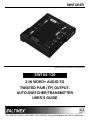
SWITCHER
MANUAL PART NUMBER: 400-0426-006
SW104-130
2-IN VIDEO+ AUDIO TO
TWISTED PAIR (TP) OUTPUT,
AUTO-SWITCHER/TRANSMITTER
USER’S GUIDE
SWITCHER
TABLE OF CONTENTS
Page
PRECAUTIONS / SAFETY WARNINGS................ 2
GENERAL..........................................................2
INSTALLATION..................................................2
CLEANING.........................................................2
FCC NOTICE .....................................................2
ABOUT YOUR SW104-130 ...................................... 3
TECHNICAL SPECIFICATIONS.............................. 3
PRODUCT DESCRIPTION ...................................... 5
APPLICATION DIAGRAMS...................................... 5
DIAGRAM 1: TYPICAL SETUP ..........................5
DIAGRAM 2: INTERNAL VIEW ..........................6
INSTALLING YOUR SW104-130 ........................... 7
OPERATION ............................................................... 7
VIDEO EQUALIZATION .....................................7
SWITCH MODES ...............................................7
TROUBLESHOOTING GUIDE................................. 8
LEDS ARE OFF ..................................................8
UNIT DOES NOT AUTO-SWITCH......................8
NO DISPLAY......................................................8
ALTINEX POLICIES .................................................. 9
LIMITED WARRANTY/RETURN POLICIES .......9
CONTACT INFORMATION ................................9
400-0426-006
1
SWITCHER
PRECAUTIONS / SAFETY WARNINGS
1.4 CLEANING
1
Please read this manual carefully before using your
SW104-130 Switcher. Keep this manual handy for
future reference. These safety instructions are to
ensure the long life of your SW104-130 and to
prevent fire and shock hazards. Please read them
carefully and heed all warnings.
•
1.1 GENERAL
•
1.5 FCC NOTICE
•
Unauthorized personnel shall not open the unit
since there are high-voltage components inside.
• Qualified ALTINEX service personnel or its
authorized representative must perform all
service.
1.3 INSTALLATION
•
•
•
•
•
•
•
•
For best results, place the SW104-130 on a flat,
level surface in a dry area away from dust and
moisture.
To prevent fire or shock, do not expose this unit
to water or moisture. Do not place the
SW104-130 in direct sunlight, near heaters or
heat-radiating appliances, or near any liquid.
Exposure to direct sunlight, smoke, or steam can
harm internal components.
Handle the SW104-130 Switcher carefully as
dropping or jarring can damage internal
components.
Do not place heavy objects on top of the
SW104-130.
To turn off the main power, be sure to remove
the cord from the power outlet. The power outlet
should be installed as near to the equipment as
possible, and should be easily accessible.
Do not pull the power cord or any cable that is
attached to the SW104-130.
If the SW104-130 is not used for an extended
period, disconnect the power cord from the
power outlet.
400-0426-006
Unplug the SW104-130 power cord before
cleaning. Clean surfaces with a dry cloth. Never
use strong detergents or solvents such as
alcohol or thinner. Do not use a wet cloth or
water to clean the unit.
•
2
This device complies with Part 15 of the FCC
Rules. Operation is subject to the following two
conditions: (1) This device may not cause
harmful interference, and (2) this device must
accept any interference received, including
interference that may cause undesired
operation.
This equipment has been tested and found to
comply with the limits for a Class A digital device
pursuant to Part 15 of the FCC Rules. These
limits are designed to provide reasonable
protection against harmful interference when the
equipment is operated in a commercial
environment. This equipment generates, uses,
and can radiate radio frequency energy and, if
not installed and used in accordance with the
instructions found herein, may cause harmful
interference to radio communications. Operation
of this equipment in a residential area is likely to
cause harmful interference in which case the
user will be required to correct the interference
at his own expense.
Any changes or modifications to the unit not
expressly approved by ALTINEX, Inc. could void
the user’s authority to operate the equipment.
SWITCHER
ABOUT YOUR SW104-130
2
TECHNICAL SPECIFICATIONS
Specifications are subject to change.
See www.altinex.com for up-to-date information.
SW104-130
2-In Video+ Audio to TP Output,
Auto-Switcher/Transmitter
with Local Output
FEATURES/
DESCRIPTION
SW104-130
Inputs
The SW104-130 Auto-Switcher is designed to
switch between two video+ audio sources. The
selected source is converted and transmitted using
ALTINEX’s Twisted Pair standard as well as
buffered and output locally. The SW104-130 is
designed for use with an equivalent ALTINEX TP
Receiver such as the TP115-111.
The SW104-130 features three modes of operation:
auto, manual, and remote. In auto mode, Input 2 is
the default selection and the SW104-130
automatically switches to Input 1 on signal
detection. In manual mode, the input is selected
using a switch on the side of the unit. Remote
switching is made via a contact closure connected
to the Input Select jack. The contact may be
controlled manually, or by using a control system.
Video
15-pin HD female (2)
Audio
3.5 mm female (2)
Contact Closure
2.5mm DC power jack (1)
Power
2.5mm DC power jack (1)
Outputs
Local Video
15-pin HD female (1)
Local Audio
3.5 mm female (1)
CAT-5/6 Twisted Pair
RJ-45 female (1)
Compatibility
The unit is encased in a solid metal enclosure and
ships with an external power adapter. The
SW104-130 is perfect for applications that use wall
or floor plates for auto-switching. The SW104-130
may be mounted to furniture or other suitable
surfaces using optional hardware.
Video Signal
Resolutions
ALTINEX Standard for
Twisted Pair
VGA through UXGA
480p through 1080i
VGA:
640x480@60Hz
900 ft (274 m)
Recommended Max.
Cable Lengths
XGA:
Signal Types
The latest generation of Twisted Pair devices uses
an innovative, patented technology* developed by
ALTINEX. The new signal processing technology
allows transmitting and receiving fully equalized
computer video signals, stereo, and audio signals
over long distances.
1024x768@60Hz
700 ft (213 m)
Note: Measurements
made using ALTINEX SXGA: 1280x1024@60Hz
low-skew cable,
650 ft (198 m)
CB3150PV.
UXGA: 1600x1200@60Hz
600 ft (183 m)
Accessories Included
* US Patent 7,065,190
Power Adapter
Table 1. SW104-130 General
400-0426-006
3
3
+9 VDC, 1.1 A
SWITCHER
MECHANICAL
SW104-130
ELECTRICAL
Material
0.091 in Al
Video Input Signal
SW104-130
Finish
Black
Height
0.960 in (24 mm)
Video Impedance
75 ohms
Width
4.300 in (109 mm)
SYNC Signal
TTL (+/-)
Depth
5.200 in (132 mm)
SYNC Impedance
10 kohms
Weight
1.00 lb (0.45 kg)
Audio Input Signal
T° Operating
10°C-35°C
T° Maximum
50°C
Humidity
Video Signal
Impedance
10 kohms
Level
0.9 Vp-p max
Twisted Pair Output
90% non-condensing
MTBF (calculations)
1.5 Vp-p max
40,000 hrs (min.)
CAT-5/6 Twisted Pair
Table 2. SW104-130 Mechanical
Video/Sync/Audio Signals
ALTINEX Standard
Local Video Output
Video Gain
0 dB
Video Impedance
75 ohms
Sync Signal
TTL (+/-)
Video Resolutions
VGA through UXGA,
480p through 1080i
Local Audio Output
Impedance
1 kohm
Local Gain
0 dB
Power Consumption
External Adapter: 9 VDC
Table 3. SW104-130 Electrical
400-0426-006
4
450 mA (4W max.)
SWITCHER
PRODUCT DESCRIPTION
4
LOCAL
MONITOR
COMPUTER/
COMPONENT
VIDEO
INPUT1
AUDIO LOCAL
OUTPUT
AUDIO
INPUT1
4TP MAIN
OUTPUT
VIDEO
EQUALIZATION
COMPUTER/
COMPONENT
VIDEO
INPUT2
CONTACT
CLOSURE
AUDIO
INPUT2
CONTROL
SWITCH
POWER
APPLICATION DIAGRAMS
5
DIAGRAM 1: TYPICAL SETUP
TP115-111
SW104-130
400-0426-006
5
SWITCHER
DIAGRAM 2: INTERNAL VIEW
SW 104-130
CONTROL
LEFT
AUDIO STEREO
3.5 mm
(VIDEO 1)
AUDIO STEREO
3.5 mm
(VIDEO 2)
RIGHT
LOCAL
3.5 mm
AUDIO MONO
LEFT
RIGHT
CH1
CONTACT
CLOSURE
CONTROL
SWITCH
CH2
RED
VIDEO INPUT1
COMPUTER/
COMPONENT
15-PIN HD
BLUE
GREEN
HOR
PLUG AND PLAY
VER
CONTROL
HOR
VER
SYNC
PROCESSING
H/W
PAIR 4
EQ
VIDEO INPUT2
COMPUTER/
COMPONENT
15-PIN HD
PAIR 1
RED
OUTPUT
TWISTED PAIR
RJ-45
PAIR 3
BLUE
PAIR 2
GREEN
PLUG AND PLAY
CONTROL
GREEN
BLUE
RED
HOR
VER
POWER
2.5 mm
9V,1A
400-0426-006
PS
POWER
6
LOCAL MONITOR
COMPUTER/
COMPONENT
15-PIN HD
SWITCHER
INSTALLING YOUR SW104-130
6
OPERATION
Step 1. Make sure to use the ALTINEX power
adapter supplied with the unit. Connect
the power adapter to the power port. The
Power and Input 2 LEDs should turn on.
The SW104-130 requires only one adjustment to be
made for optimal performance. The adjustment is
video equalization for long cable lengths. The
remaining controls are for input selection only.
7.1 VIDEO EQUALIZATION
NOTE: Input 2 is the default if there is no
signal on Input 1 and the Control
Switch is in the Auto position.
Video equalization is provided to fine-tune the
displayed image on the remote display. The
equalization adjustments on the SW104-130
and Twisted Pair receiver work together.
Step 2. Connect a video and audio source to
Input 1. If there is a properly formatted
input signal on Input 1, the switcher will
switch to Input 1 automatically, and the
Input 1 LED will turn on.
Start by setting both units to minimum and then
increase slowly. Some monitors respond very
quickly to changes in the equalization, others
may not display an image until the equalization
is set precisely.
Step 3. Connect a video and audio source to
Input 2. If there is a properly formatted
input signal on Input 1, the switcher will
remain on Input 1.
7.2 SWITCH MODES
7.1.1 AUTO-SWITCH MODE
Step 4. Connect the local video and audio outputs
to the local monitor and speakers.
In auto-switch mode, the SW104-130 automatically
selects Input 2 if no active signal is present on
Input 1. If a signal is on Input 2 and not on Input 1,
the SW104-130 will maintain Input 2. However,
when an active signal is applied to Input 1, the
SW104-130 will switch to Input 1. If active signals
are on both inputs, the SW104-130 will
automatically switch to Input 1.
Step 5. If a remote switch is to be used, connect
the control cable to the Input Select port.
See Section 7 for operation control.
Step 6. Verify that the picture quality on the
display is good. If a signal is not being
received, make sure that the display is
compatible with the resolution of the
computer graphics card.
7.1.2 MANUAL-SWITCH MODE
The SW104-130 control switch allows switching
between Input 1 and Input 2. Placing the control
switch in either the Input 1 or Input 2 position forces
the source signal to the main and local outputs
thereby disabling auto-switching.
Step 7. Connect the 4TP Main Output to the input
of the Twisted Pair receiver.
NOTE: Connect the Twisted Pair
receiver per its instructions.
Step 8. The SW104-130 is now ready for
operation. Depending on the length of the
cable, the video equalization adjustment
may need to be adjusted for optimal
performance.
400-0426-006
7
7.1.3 REMOTE SWITCH MODE
Remote switching is achieved via a contact closure
on the Input Select jack. Remote switching mode
disables both auto-switching and the Control Switch
position. A closed contact selects Input 1 and an
open contact selects Input 2.
7
SWITCHER
TROUBLESHOOTING GUIDE
Cause 3:
8
We have carefully tested and found no problems in
the supplied SW104-130 unit. However, we would
like to offer the following suggestions:
Solution 1: Remove the input signals from the
switcher. If the Input 2 LED is off,
call ALTINEX at (714) 990-2300. If
the Input 2 LED is on, see
Solution 2.
8.1 LEDs ARE OFF
Cause 1:
The power adapter is installed
wrong.
Solution 2: Connect a properly formatted video
type signal to Input 1. If the switcher
does not switch to Input 1, see
Solution 3.
Solution 1: Make sure the adapter output is
connected to the power input jack on
the unit. If one of the LEDs is still not
on, see Solution 2.
Solution 3: Bypass the switcher and connect the
output of the source directly to the
display. If the display is good, then
see Cause 4.
Solution 2: Ensure the adapter is plugged into
an AC outlet that has power. If the
adapter has AC power and the LEDs
are still off, see Cause 2.
Cause 2:
The wrong
installed.
power
adapter
The signal is not active or is
improperly formatted.
Cause 4:
is
The wrong
installed.
power
adapter
is
Solution 1: Please use the ALTINEX-supplied
external adapter. If the unit still does
not
auto-switch,
please
call
ALTINEX at (714) 990-2300.
Solution 1: Please use the ALTINEX supplied
external adapter. If one of the LEDs
is still not on, please call ALTINEX
at (714) 990-2300.
8.3 NO DISPLAY
8.2 UNIT DOES NOT AUTO-SWITCH
Cause 1:
The source has a problem.
Cause 1:
The remote override switch is
installed.
Solution:
Solution:
Remove the connection to the Input
Select jack on the unit. If a plug is in
the jack, even without a switch
connected, the SW104-130 will not
auto-switch properly. If the unit does
not auto-switch with the plug
removed, see Cause 2.
Check the source and make sure
that there is a signal present and all
source connections are correct. If
the source is working and there is
still no display, see Cause 2.
Cause 2:
Manual override is ON.
Solution:
Make sure there is nothing
connected to the Input Select port
on the switcher. If there is nothing
connected, see Cause 3.
Cause 2:
The control switch is not in the
auto position.
Solution:
Switch the Control Switch to the
auto position. If the unit does not
auto-switch, see Cause 3.
400-0426-006
8
SWITCHER
Cause 3:
Signal is bad or missing.
ALTINEX POLICIES
Solution 1: Make sure the switcher output is
connected to the monitor. If there is
still no display, see Solution 2.
9.1 LIMITED WARRANTY/RETURN POLICIES
Please see the ALTINEX website at
www.altinex.com for details on warranty and
return policies.
Solution 2: Remove both inputs to the switcher
and connect the active signal from
the source to Input 2. If there is still
no display, see Solution 3.
9.2 CONTACT INFORMATION
ALTINEX, Inc.
Solution 3: Bypass the switcher and connect the
output of the source directly to the
monitor. If the display is good, then
call ALTINEX at (714) 990-2300. If
there is still no display, see Cause 4.
Cause 4:
Cable connections are incorrect.
Solution:
Make sure the cables are properly
connected. Also, make sure that the
continuity and wiring are good. If
there is still no display present, see
Cause 5.
Cause 5:
The display has a problem.
Solution:
Make sure the display is powered
and is turned on. If there is still no
display, please call ALTINEX at
(714) 990-2300.
400-0426-006
9
592 Apollo Street
Brea, CA 92821 USA
TEL: 714 990-2300
TOLL FREE: 1-800-ALTINEX
WEB: www.altinex.com
E-MAIL: [email protected]
9