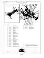
1
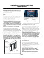
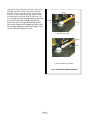
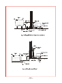
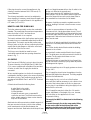
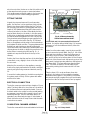
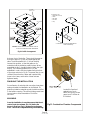
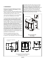
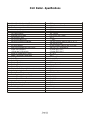
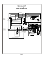
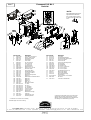
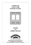
CHARNWOOD OLX
Oil Fired
Hearth Boiler
Operating
and
Installation Instructions
Bishops Way, Newport, Isle of Wight, PO30 5WS
Tel: +44 (0)1983 537799 Fax: +44(0)1983 537788
E-Mail: [email protected] Internet: www.charnwood.com
CHARNWOOD OLX45
Operating and Installation Instructions
Operating Instructions
General Points ........................................................4
Fuel..........................................................................4
Controlling The Boiler ............................................4
Electric Flame Effect and Fan Heater ......................4
If The Burner Fails to Light......................................4
Maintenance............................................................4
Replacing the Flame Effect Bulb...............................4
Installation Instructions
Health & Safety Precautions....................................6
Standards & Regulations..........................................6
Performance...........................................................6
Air Supply...............................................................6
Chimney..................................................................6
Hearth & Fire Surround..........................................8
Oil Supply................................................................8
Preparation of the Fireplace....................................9
Central Heating System...........................................9
Fitting The Fire.......................................................10
Electrical Connection..............................................10
Combustion Chamber Assembly............................10
Finishing The Installation.........................................11
Commissioning.......................................................12
Overall Dimensions................................................12
Specifications..........................................................14
Wiring Diagram......................................................15
Electrode Settings...................................................16
Exploded Parts Drawing - Boiler.............................17
Exploded Parts Drawing - Burner...........................18
Bishops Way, Newport, Isle of Wight, PO30 5WS
Technical Support Tel: +44 (0)1983 537799 Fax: +44(0)1983 537788
E-Mail: [email protected] Internet: www.charnwood.com
Page 3
OLX V5.2 05.04
Charnwood OLX Oil Fired Hearth Boiler
Operating Instructions
GENERAL POINTS
Before using the boiler for the first time, check with the
installer that it has been correctly installed and
commissioned. Do not attempt to use the boiler before
it has been commissioned.
FUEL
The boiler is set up to burn 28 sec. viscosity oil, this is
commonly known as Kerosene. Do not use Gas Oil.
Burner Reset Button
Located Through Hole
In Front Panel
CONTROLLING THE BOILER
The boiler is controlled by the thermostat which is on
the left hand side of the fire, it is the lower of the two
control knobs (see Fig. 1.) This sets the temperature
that the boiler will operate at. A Central Heating Time
Clock or Programmer will normally control the heating
system.
ELECTRIC FLAME EFFECT & FAN HEATER
The electric flame effect operates completely
independently from the boiler and is switched on and
off by the top control knob on the left hand side of the
fire (see Fig. 1.) Turn the knob to position "1" to
operate the flame effect. The flame effect may take a
few moments to become established when first
switched on after long periods of not being used.
Position "2" is used for the 1KW setting of the optional
fan heater if fitted. Position “3” is the 2KW setting. If
the room temperature becomes excessive, the internal
thermostat will switch the heater to blow cool air until
the temperature falls, when it will revert to its previous
setting.
Serial number Label
Inner plate
Bottom plate
Fig 2. Burner Reset Button
IF THE BURNER FAILS TO LIGHT
If the burner fails to light then the Reset light on the
Burner Reset Button may light up (see Fig. 2.) This
situation is known as “Lockout” in which case wait for
1 minute and press the re-set button (located through
the hole in the front panel behind the doors.) The
burner will then try to ignite again.
If the burner continually goes to lockout, then the cause
needs to be established and the problem put right. The
most common causes are lack of fuel, or air in the fuel
line. Check that the oil tank is not empty, and that all
valves are open. The troubleshooting guide gives
further steps, some of which will require action by a
trained Oil Engineer. Do not press the reset button
more than five times in a row as this can cause damage
to the pump.
MAINTENANCE
Flame Effect
and Optional
Fan Heater Control
It is important to have the appliance serviced each
year. Please arrange this with an OFTEC approved
Heating engineer. The flexible oil supply hose must be
replaced every 2 years
Replacing The Flame Effect Bulb
Boiler
Thermostat
Turn Handle
Clockwise
To Open
Fig. 1. Controls
Replacing the bulb in the flame effect is a simple
operation that can be carried out without using any
tools.
Ensure that the flame effect is switched off before
attempting to replace the bulb. Open the doors and
Page 4
OLX V5.2 05.04
remove the coals. Lift off the Front Fence. Lift out the
fibreglass coal effect. Lift the right- hand end of the
bulb and cover out of its clip, see Fig. 3, then unplug
the bulb, moving it towards the right. Slide the cover
off and discard the old bulb. Slide the old cover onto
the new bulb and insert the bulb base into the holder
on the left. Ensure that the bulb is pushed fully
home, then lower the right-hand end and press it
into the clip. Replace the fibreglass coal effect, with
the rear edge passing just under the Perspex. Re-fit
the front fence and replace the coals.
Sleeve
Holder
Clip
1) Lift Bulb from clip
Sleeve
Bulb
2) Remove Bulb from Holder
Fig. 3. Flame Effect Bulb Replacement
Page 5
OLX V5.2 05.04
Charnwood OLX Oil Fired Hearth Boiler
Installation Instructions
HEALTH AND SAFETY PRECAUTIONS
Please take care when installing the appliance that the
requirements of the Health and Safety at Work Act
1974 are met.
Some types of fire cement are caustic and should not
be allowed to come into contact with the skin. In case
of contact wash with plenty of water.
No asbestos is used in the appliance but if there is a
possibility of disturbing any asbestos in the course of
installation then appropriate protective equipment must
be used.
When handling insulating materials a suitable face mask
and protective gloves should be worn.
Take care when handling fuel oil which can cause skin
irritation, avoid contact with the skin or clothing, take
care to wash hands well after contact with fuel oil and
before eating. Fuel oil must never be taken internally.
STANDARDS & REGULATIONS
In addition to these instructions the requirements of the
following standards must be fulfilled:
BS 5410 Pt 1 Oil Installations Under 45 kW
BS 5449 Forced Circulation hot water central
heatingsystems for domestic premises
BS 7671 Electrical Wiring Regulations
boiler and a ducted air supply must be provided to the
right hand side of the boiler at this point. A two metre
length of flexible ducting and fixing clips are supplied
with the appliance to connect the air input from the
appliance silencer to the rigid plastic ducting. The air
pipe should be sealed into the appliance using a silicone
sealant. The ducting should be run in 50 mm dia. (2")
plastic pipe and must terminate in free air - preferably
either outside or in a ventilated loft space. The end of
the ducting must be fitted with a suitable cage to
prevent entry by birds or small mammals. The ducting
should be boxed in where it passes through living areas.
The length of ducting should be kept to a minimum,
and the maximum recommended length is 10 metres
incorporating up to 4 bends. (One bend is approx.
equivalent to 1 metre of straight pipe).
Provided that the ducting terminates as described
above there is no requirement for a separate
combustion air supply in the room in which the
appliance is installed. However, if the ducting
terminates within a living space then there must be an
adequate air supply into that room totalling at least 55
sq. cm. (8.5 sq. inches) to provide combustion air.
CHIMNEY
The chimney should comply with BS5410: Part 1 and
must meet Building Regulations.
Local Authority Bylaws and Building Regulations
regarding the installation of Oil Burning Appliances,
flues and chimneys and The Control of Pollution (Oil)
Regulations must also be observed.
The diameter of the chimney must not be less than 100
mm (4”) internal diameter.
Oil boilers should be installed in accordance with good
practice as recommended by OFTEC (The Oil Firing
Technical Association for the Petroleum Industry,
Banstead, Surrey. Tel: 01737 373311.)
PERFORMANCE
The output of the boiler is adjustable between 11-13
kW(38-44,000 Btu/h), a small amount of heat will be
given out to the room but for purposes of sizing the
system this should be ignored. The optional Fan Heater
provides up to 2KW of heat to the room.
AIR SUPPLY
The air supply for combustion is taken from within
the builders opening on the right-hand side of the
As the boiler operates at high efficiency, it is important
that the chimney is well insulated in order to prevent
condensation forming.
Brick or stone chimneys should be lined with a suitable
liner. If a stainless steel liner is used in a brick or stone
chimney then it must be insulated between the liner and
the brickwork in order to prevent condensation that
can reduce the life of both the liner and the boiler.
Pumice liners will give the required level of insulation.
As the flue outlet temperature is below 250°C stainless
steel flexible flue liners suitable for oil may be fitted
directly onto the appliance, although in the interests of
reducing flue noise it is preferable to use a 600 mm
length of rigid flue pipe from the appliance to the liner.
Page 6
OLX V5.2 05.04
Page 7
OLX V5.2 05.04
If flue pipe is used to connect the appliance to the
chimney it must be between 100 & 125 mm (4-5")
internal diameter.
The chimney termination must not be subjected to
down draughts. If necessary an anti-down draught cowl
may be fitted. The required draw for this appliance is
0.17 mbar (0.07 in H2O).
HEARTH AND FIRE SURROUND
The boiler waterways totally enclose the combustion
chamber. This means that the maximum temperature
below the boiler is 100°C and therefore a
constructional hearth is not required.
The hearth and base within the fireplace opening must
be made from non-combustible material and must be
flat and level. The hearth must be flat to allow easy
fitting of parts on the fire. When positioning the boiler
ensure that the side flanges on the boiler come level
with the face of the fire surround.
The fire surround should be made from non
combustible material and have opening dimensions
shown in Fig. 7 .
per 1m of length downwards from the oil outlet to the
sludge cock fitted at the opposite end.
Plastic tanks should be UV stabilised for protection
from sunlight. They do not need to stand on piers but
should be supported across the entire base. Refer to
the manufacturers instructions for full details.
Be aware of pollution prevention regulations and the
need for bunding if the tank is close to water courses
or drains.
In order to ensure quietness of operation of the
Charnwood OLX a single pipe system is used. The oil
storage tank should ideally be positioned with the base
of the tank higher than the base of the fire. When the
storage tank is below the level of the burner then an oil
lifter must be used.
An oil shut off valve is supplied with the boiler to allow
the burner to be easily disconnected and minimise oil
spillage.
An oil filter should also be fitted outside the building,
adjacent to the oil tank.
A protective fire valve must be fitted in the oil supply
line. The phial sensor should be mounted in the burner
chamber The fire valve should have a cut out
temperature of 90°C.
Soldered joints are not permitted in the oil supply line,
and all connections must be properly sealed to prevent
oil leakage and air ingress.
OIL SUPPLY
The Charnwood Oil Boiler is set up to burn Kerosene
28 second viscosity oil to BS2869 Part 2 1988 Class
C2. It comes complete with a flexible oil line and shut
off valve, to which the oil supply line should be
connected.
Some schematic layouts of oil supply systems are shown
in Figs. 4 & 5.
When considering where to site the oil storage tank,
consideration should be given to the access required by
fuel delivery lorries. Tank positioning must also be in
accordance with BS5410 Part 1 and OFTEC Technical
Book 3.
Oil tanks should have the following items:
A valve fitted to the outlet
Sludge valve (on steel tanks)
Oil level indicator
Hinged fill and vent cover or separate fill
connection and vent. The fill and vent must be
either suitably capped or have a return bend to
keep out dirt and water.
The oil supply line should enter the appliance from the
left-hand side behind the side panel. The fitting supplied
with the fire facilitates this.
If the supply line is to run in front of the fireplace
surround then it will be necessary to cut a section from
the end of the bottom plate on the fire to give access
for the pipe. It is preferable to bring the supply in from
behind the fire surround.
The oil supply line may be in either 8 or 10 mm dia.
copper, dependant on the length of the run, however,
the connection on the appliance is a 10 mm
compression fitting.
Steel tanks should be mounted on suitable supports. If
they are mounted on blocks or bricks then a damp
proof membrane should be fitted between the
supports and the tank. Steel tanks should slope 20 mm
The supply line MUST be flushed out in the following
manner:Connect the supply line to the compression fitting
on the service valve at the left hand side of the
appliance, but disconnect the flexible hose from the
other side of the service valve, and replace it with
Page 8
OLX V5.2 05.04
the push on piece of 12 mm bleed tube supplied.
Place the other end of the bleed tube into a suitable
receptacle, and flush out the supply line by turning
on the service valve. When the oil is clean, turn off
the service valve, remove the bleed tube, and reattach the flexible tube from the burner. Turn the
service valve back on, check for leaks, and clean up
any spilt oil.
Vermiculite infill
100mm id single skin
flexible flue pipe
around Flexible
Liner
Fire s u rround with
removable metal
closure panels
PREPARATION OF FIREPLACE
When replacing an existing boiler, remove any fireback
and infill material to expose the builders opening.
The opening must be at least 400 mm deep (when
measured from the front face of the surround,) 600
mm wide (to give access to the boiler connections,) and
650 mm high (to give access to the flue connection.
Ensure that the base of the fireplace is level with the
hearth and that the face of the surround is vertical.
It is necessary to have a small cut out in the fireplace
surround at the bottom left of the opening in order to
bring the oil and electrical supply to the fire. It is also
necessary to have a small cut out at the bottom right of
the opening to clear the air inlet duct. See fig. 7.
Rockwool infill
around flexible
liner above closure
High Temperature
Silicone sealant.
Closure Plate
Appliance Connector
Rockwool
insulation
around
Appliance
Flue fixing brackets
Joint caulked with
glass fibre rope and
sealed with high
temperature silicone
sealant.
Fig. 6. Typical Instalation
using flexible flue liner
right down to Appliance.
The shaded area on the face of
the surround is the minimumflat
area required.
670 mm
770 mm
CENTRAL HEATING SYSTEM
50mm
65mm
50mm
The central heating system must comply with BS 5449,
and should be installed in accordance with the current
good practise guidelines as advised by the HVCA.
Central heating design is a large subject which it is not
possible to deal with adequately in this manual. The
points that are particularly relevant to this boiler are
dealt with below.
Max. 470mm (18 1/2")
Min. 405mm (16")
Dim. B:
Max. 579mm (22 3/4")
Min. 555mm (21 3/4")
Fig. 7 Limiting Dimensions Of
Surround and Opening
The heating and hot water system should normally be
fully pumped, although a gravity hot water system may
be used if it already exists.
There are no internal divisions in the boiler, and any
combination of flow and return tappings may be used.
If it is possible then diagonal pairs of tappings should be
used, but pairs on the same side may be used if
required.
The maximum working pressure of the boiler must not
exceed 3 Bar ( 44 psi or a static head of 30m)
In order to prevent a build up of scale and corrosion a
suitable inhibitor should be added to the system.
When replacing an existing boiler the system should
110mm
Dim. A:
be thoroughly cleaned before connecting the new
boiler.
Fully automatic central heating controls may be used to
give full control of the heating and hot water. When
designing the control system it is important to note that
if the situation can arise where the flow of water
through the boiler is stopped, or substantially reduced,
whilst the burner is still firing, then this can result in the
water in the boiler reaching very high temperatures, or
even boiling, before the boiler thermostat can sense it
and switch the burner off. If this is a possibility then
Page 9
OLX V5.2 05.04
wire the controls to the burner so that it is switched off
at the same time as the pump or motorised valves.
This usually means wiring the supply to the burner into
the output from the central heating programmer.
Reset Button
Oil Pressure
Gauge Port
Position the fire so that the rear face of the side flanges
comes flush or very slightly in front of the face of the
fire surround.
Make the flue connection to the appliance, ensuring
that the flue pipe is well sealed to the boiler, and fixed
securely using the fixing screws and brackets, see Fig.
10.
Connect the heating system to the boiler ensuring that
the system vents correctly. Fill the system with water
and check for leaks.
Air Control 1-10
Ignition Unit
(Behind Control Unit)
Air Inlet
Manifold
Burner
Control
Unit
FITTING THE FIRE
Unpack the stove and remove it from its wooden
pallet.. If a flue liner is to be used then this should be
fitted in the chimney before fitting the fire. The liner
will normally come down to a fixing plate and a short
length of 316 Stainless steel flue pipe is then used to
connect the boiler to the liner. Alternatively the liner
may be fitted directly to the boiler, in this case ensure
that the liner is adequately supported and that it will
not vibrate when the appliance is in use. Use the Flue
Fixing brackets and self tapping screws supplied to fix
the flue securely to the boiler (see Fig. 12.) Mineral
fibre or fibreglass should be used to reduce vibrations
and insulate the boiler and flue. The space between the
flexible liner and the chimney should be filled with
loose vermiculite infill retained by a suitable plate in the
chimney above the boiler to allow future access to the
boiler without removing the infill (see Fig. 6). A
suitable rain cap should be fitted to the top of the
chimney.
Photocell
Oil Pump
Nozzle Cover Plate
Fuel Solenoid valve
Air Pressure Switch
Fig. 8. Oil Burner Assembly
Shown Removed from Boiler.
baffles fitted, and it is recommended that these be
checked for position before initial firing. If it becomes
necessary to re-fit the baffles and bricks, follow this
procedure:Isolate from the mains supply, open the doors and lift
up and remove the bottom plate. See Fig 2. Lift off the
fence and the coal effect. Loosen the fixing screw at
each side of the inner plate , slide outwards into the
slot, and lift off the inner bottom plate. Lift the Perspex
panel out of the fire and undo the two wing nuts on the
back panel. Unplug the mains cable from the bottom of
the flame effect. The flame effect may then be lifted
clear. The boiler access door is now visible, and is
removed by undoing the 4 brass nuts with a 10 mm
socket.
Take the items 1-5 in order and lower them into
position in the bottom of the combustion chamber.
Assemble them together in this position so that both
side boards are tight in against the top & back boards,
and the front face of the top board is hard up against
ELECTRICAL CONNECTION
The boiler comes pre-wired with two lengths of 3-core
cable. The black cable is for the oil burner, the white is
for the flame effect and optional fan heater. Connect
the black cable to the output from the central heating
programmer, ensuring that the supply is via a 3 amp
fused switched spur. Connect the white cable to a
separate 3 amp fused switched spur. If a fan heater is
fitted, this fuse must be 10 amp. Ensure that the earth
connections are made.
Bleed Screw
COMBUSTION CHAMBER ASSEMBLY
Bleed Hose
Connection Point
The boiler comes with the internal insulation bricks and
Page 10
OLX V5.2 05.04
Oil Pressure Adjustment screw.
Clockwise to Increase,
Anti-Clockwise to Decrease.
Fig. 9. Oil Pump Details
Top Baffle
Nibs at front
Assembly Order:
1. Base (Fibre Wool)
2. Back
3. RH Side
4. LH Side
5. Top
45° Chamfer
5
3
45° Chamfer
2
45° Chamfer
4
1
Combustion Chamber Insulation Board
Order of Assembly
Note! Numbers etched on to baffles must be
in correct orientation when assembled.
Fig 10. Baffle Arrangement
the inner front of the boiler. There should be a gap at
the back of approx. 25 mm, and equal gaps at the
sides. The bottom baffle (No. 1) is now carefully
lowered into position, so that the guides on its
underside hold the insulation panels in place. When
assembled the No 1 should be clearly visible, the right
way up. The remaining baffles (Nos. 2-4 ) are
assembled in order, with the numbers facing the front
of the stove as shown in Fig 10. The access door is now
re-fitted. Ensure that the rubber seal is pushed fully
home to the frame, and that the 4 brass nuts are
tightened evenly.
FINISHING THE INSTALLATION
Once all water, oil and electrical connections have been
made and tested the installation can be finished. Fit
glass fibre insulation material around the boiler and flue
in the builders opening. This will both help prevent heat
loss and reduce noise transmission. Fit the fire
surround.
Locate this face hard
against inner front
boiler face, giving 25mm
gap at rear, & 40mm at
front sides.
WARNING
Once the installation is complete ensure that the air
control is set at maximum (No. 10) before the
burner is fired (see Fig. 8.) Otherwise sooting may
occur. This will be re-adjusted during commissioning.
Fig 11. Combustion Chamber Components
Page 11
OLX V5.2 05.04
COMMISSIONING
The burners are pre-set at the factory, but must be
fine-tuned on completion of the installation. This is a
condition of the guarantee.
Before firing the boiler check that the baffles and blast
chamber components are fitted in the correct positions
as described above and shown in Figs. 10 & 11.
thermostat to Med. After a few seconds you should
hear the burner ignite. If necessary bleed the pump.
Refer to Fig. 9. Fit the piece of 4 mm plastic hose
provided onto the bleed port, place the end of the hose
into a suitable receptacle and open the bleed screw
taking care not to spill any oil. When bleeding the
pump will be quite noisy. Once all of the air is out of
the system close the bleed screw and remove the hose.
Take care to mop up any drops of oil spilt.
Ensure that the heating system is connected and filled
with water before attempting to fire the boiler.
Flue Fixing Brackets
To set the oil pressure and the air setting it is necessary
to remove the inner bottom plate. Isolate from the
mains supply, open the doors and lift up and remove
the bottom plate. See Fig 2. Lift off the coals, the fence
and the coal effect. Loosen the fixing screw at each side
of the inner plate , slide outwards into the slot, and lift
off the inner bottom plate. Access to the boiler
sampling point is behind the flame effect. To gain access
lift the Perspex panel out of the flame effect and undo
the two wing nuts on the back panel. Unplug the mains
cable from the bottom of the flame effect, which may
then be lifted clear. The boiler sampling point is at the
top of the access door, use a 5 mm allen key to remove
the blanking screw. Set the air control fully open (No.
10) before the initial firing. The electrical power may be
turned back on to test the burner.
Air Inlet
Connection
The burner components are shown in Fig. 8.
Turn on the supply to the programmer, set the
programmer to give heating and hot water and turn the
Fig. 12. Air Inlet and
Flue Fixings
Boiler tappings are 1” BSP Female,
2 each side
394
62
ø130
547
654
(693 with
optional
fan heater)
520
250
261
365
170
548
Charnwood OLX Overall Dimensions
(all dimensions are in mm)
Page 12
OLX V5.2 05.04
255
Write the date on the flexible oil line label.The
flexible oil line MUST be replaced every 2 years.
Allow the fire to run for 20-30 minutes before checking
the soot and CO2 readings. The sampling point is on
the boiler access door. The air control is situated on the
front of the black rubber air manifold which is towards
the right of the burner, as shown in Fig. 8. Initially set to
No. 10, the burner will be burning with excess air and
with the oil pressure set at a mid-range setting. Fit a
pressure gauge to the pressure gauge port shown in
Fig. 8 and adjust to the required setting (100-140 psi.)
After adjusting the pump pressure allow the fire to run
for approximately 10 minutes before checking the
smoke reading. Reduce the air inlet by slackening the
nut in the centre of the manifold, moving the pointer
clockwise to a lower notch and re-tightening the nut .
When soot occurs, gradually increase it to give
combustion free of soot. (10 = max air, 1 = min air ).
This should give 11–12% CO2 and 0-1 Smoke with a
flue temperature of approximately 180°C above
ambient. Measurements taken at the boiler access door
will give a slightly higher temperature (approx. 220°C
above ambient) than readings taken actually in the flue.
A modern burner works with less excess air and often
also with smaller nozzles than older models. This
increases the efficiency but also the risk of
condensation in the chimney. The risk increases if the
area of the chimney flue is too large. The temperature
of the flue gases should exceed 60°C measured 0.5
metres from the chimney top. If necessary some of the
following measures may be taken to raise the chimney
temperature:
Insulate the chimney in cold attics.
Install a chimney liner.
Install a draught regulator (dilutes the flue gases during
operation and dries them up during standstill).
Increase the oil quantity.
Raise the flue gas temperature by removing some of
the baffle plates in the boiler.
Re-fit the Electric Flame effect and check its operation.
The flame pattern may take a few minutes to become
established, particularly when the fire is switched on for
the first time. Arrange the coals supplied with the
appliance on top of the fibreglass coal effect to produce
a beautiful fire.
Advise the customer on the use of the boiler, and the
system controls. Also advise of the need for annual
servicing of the boiler by an OFTEC trained &
registered technician. Leave these Operating and
Installation Instructions with the customer.
Page 13
OLX V5.2 05.04
OLX Boiler - Specifications
Max. Allowable Operating Temperature
Max. Allowable Operating Pressure
Test Pressure
Heat Output Range
Heat Input at Rated Output
Oil Pump Pressure
Required Flue Draught
Exit Flue Gas Temp
Exit Flue Gas Mass Flow
Exit Flue Connection Diameter
95°C
3 bar (Pressure Class 2)
4.5 bar
11-13 kW
15 kW
110 - 140 psi
0.07 in H2O (0.17 mbar)
205°C
……kg/s
130 mm socket to take 125 mm (5 in) or
100 mm (4 in) pipe
55 mm socket to take 50 mm (2 in) pipe
10M + 4 x 90° Swept Bends
4.1 mbar @DT=10°C
1.5 mbar @DT=20°C
40 - 90°C
110°C
Kerosene 28 second
On / Off Type
1 in BSP Female
IP20
Copper Flashed Steel
240v 50 Hz
200 Watts
2200 watts
250v 2A x 20 mm
Air Inlet Diameter
Max. Recommended Air Pipe Length
Water-side Resistance
@ flow rate 2.9 litres/min
Range of Temperature Control
Safety Thermostat Temperature
Fuel Type Used
Boiler Type
Boiler Tapping size
Electrical Protection
Earthing Terminal
Electrical Supply
Electrical Power Input @ 240v ac (standard)
(with fan heater)
Fuse in Flame Effect
Fuses Required in Power Supply
Flame Effect only
Flame Effect + Fan Heater
Burner
Fire Valve Operating Temperature
Boiler Water Volume
Total Weight of Stove
3A 240V
10A 240V
3A 240V
90°C
23.4 Litres
140 Kg
Page 14
OLX V5.2 05.04
Charnwood OLX
Wiring Diagram
Above Serial No.1562
IEC Lead Socket to
Flame Effect
Skt1
E
Skt2
E
L
L
N
N
IEC Fused
Chassis Plug in
Flame Effect
Fan Heater
Plug
L1
Mains Input
from 13Amp
Fused Spur.
E
P1
1
N
Fluorescent Light
Brown
(1+)
1+
3
2
L
1 amp antisurge fuse
L2
Ballast
Black
(1-)
Rotary Switch SW1
Type RPSBC 2 0 M 90
1-
N
Fan
Flame Effect
Blue
(2-)
2-
E
Satronic Control Terminals
Green/
Yellow
(2+)
2+
Socket To
Optional
Fan Heater
1
Wire Colours
from Fan Heater
2
A
3
4
5
6
B
7
8
9
N
10
N
N
C
S2
Photocell
Skt 3
Mains Input
from Timer
Switched Live.
Fused at 3Amp.
E
E
31
32
N
N
21
22
L
L
11
12
E
N
L
Skt 4
TR TB
AirPressure
Switch
P
Ignition Unit
IEC Chassis
Outlet Socket
Dual Acting
Thermostat
IEC Lead
Plug to
Burner
Oil
Pump
Fan
Diode
Burner Control
TS1
Thermostat Mounting Box
Page 15
OLX V5.2 05.04
SolenoidValve
(Oil)
Charnwood OLX
Electrode Settings
0.5 ±0.5
3.0 ±0.2
9.0 ±1.0
All dimensions are in mm
Page 16
OLX V5.2 05.04
Issue C
Charnwood OLX Mk.2
Parts List
32
NOTE!
53
25a
31
Mk.3 Replacement Burners for
appliances before Serial No.
45****1562 require bracket
to align control box with re-set
hole.
24b
48
54
24a
23a
36
21a
21a
55
21a
21a
38
49
17
30
34
14 15
40
26
37
19 18 39
46
29
16
12
11
6
45 44
51
47a 47b 47c
35
50
52
9
28
8
43
7
41
4
42
20
13
27
10
33
Item Part No.
Description
Item Part No.
Description
3*
4
5*
6
7
8
9
10
11
12
13
14
15
16
17
18
19
20
21a
23a
24a
24b
25a
26
27
28
29
30
31
32
33
34
35
36
37
Door Seal Set Inc. Adhesive
Glass Inc. Glass Channel
Glass Seal (Neoprene)
Glass Retainer
Front Firebar
R.H. Door Handle
Door Catch Cam
L.H. Door Knob
Thermostat Knob
Flame Effect Knob
Hinge Pin Set (4 per set)
Fluorescent Lamp
Amber Lamp Sleeve
Reset Button Extension
Access Door Insulation
Thermostat
Flame Effect Rotary Switch
Hinge Post
Blast Chamber Insulation Board Set
Baffle -No.1
Baffle -No.2.
Baffle No.3
Baffle - No.4
Fibreglass Coal Effect
L.H. Door
R.H. Door
L.H. Side Panel
R.H. Side Panel
Lower Hood Panel
Top Hood Panel
Bottom Panel
Flame Effect Cartridge
Oil Burner
Firebox/Boiler (OLX)
Panel Fixing Bracket
38
39
40
41
42
43
44
45
46
47a
47b
47c
48
49
50
51
52
53
54
55
Access Door
Thermostat Mounting Box
Thermostat Phial Clamping Plate
Inner Front Insulation
Inner Front Plate
Inner Front Plate Fixing Bracket
Air Inlet Gasket
Air Inlet Manifold
Air Inlet Side Cover
Air Control - Location Disk
Air Control - Pointer
Air Control - Adjuster
Flue Fixing Bracket (set of 3)
Back Ceramic Gasket
Service Valve & Elbow
Burner Mounting Flange
M12 Half Nuts
Lower Top Panel - for Fan Heater
Fan Heater
Control Box Offset Bracket
008/KV35S
006/KV18
008/TV95
004/KV23
002/TV07
008/KV16
002/KV14
008/KV13
008/TV19
008/TV20
008/BW39/S
008/TV80
008/TV78
040/TV69
008/TV09
008/TV22
008/TV24
008/TV27
011/TV106
010/TV31
010/TV47A
010/TV47B
010/TV48A
008/TV13
003/TV01/##
003/TV02/##
005/TV04/##
005/TV05/##
005/KV06/##
005/KV09/##
005/TV16/##
008/TV11
008/TV15
001/TV10B
004/KV50
CHARNWOOD
Bishops
005/TV06/##
008/TV111
010/TV137
To obtain spare parts please contact your local stockist
giving Model, Part number and Description. In case of
difficulty contact the manufacturer at the address shown.
This drawing is for Identification purposes only.
* These items are not shown on the drawing
## Please specify colour when ordering
T:+44 (0)1983 537799
004/TV03
004/TV25
004/TV33
008/TV17
010/TV14
010/TV43
008/TV86
008/TV49
010/TV84/1
010/TV108
010/TV109
010/TV110
010/TV42S
011/PV27
040/TV77
040/TV94
Way, N e w p o r t , Isle of Wight P O 3 0 5WS, U n i t e d Kingdom
F:+44 (0)1983 537788
[email protected]
Page 17
OLX V5.2 05.04
www.charnwood.com
Issue A
Charnwood OLX Burner Mk.3
Parts List
17
These Items shown Rotated
3
42
23
12
24
5
34
6
7
35
8
15
30
16
27
4
40
2
28
1
18
41
22
26
9
29
31
19
11
25
38
14
37
10
Item
Part No.
1
040/TV61
2
040/TV154
3
040/TV153
4
040/TV140
5
040/TV155
6
040/TV141
7
040/TV143
8
040/TV142
9
040/TV144
10
040/TV160
11
040/TV63
12
040/TV112
13
040/TV113
14
040/TV164
15
040/TV151
16
040/TV28
17
040/TV74
18
040/TV92
19
040/TV72
20
040/TV71
21
040/TV75
22
040/TV54/A
23
040/TV158
24
040/TV159
25
040/TV68
26
040/TV148
27
040/TV149
28
040/TV150
29
040/TV69
30
040/TV152
31
040/TV146
33
040/TV145
34
040/TV15~1
35
040/TV163
37
040/TV147
CHARNWOOD
Description
Nozzle - 0.4 80° EH
Electrode Mounting Block
Electrode
Nozzle Holder
Nozzle Holder Cover Plate
Al. Washer
Banjo Union
Fibre Washer
Banjo Bolt
Flexible Oil Line
Blast Tube Seal
Photocell Plug-in Type
Solenoid Coil Plug-in Type
Blast Tube
Air Guide in Blast Tube
Burner Chassis Plate
Fan Motor & Impeller
Pump Mounting Bracket
Oil Pump
Ignition Unit
Control Box
Fan Mounting Ring
Photocell Plug & Cable
Photocell Holder
Air Pressure Switch
Gauge Port Elbow
Gauge Port Plug
Oil T Connector
Reset Button Extension
Blast Tube Mounting Flange
Oil Pipe (Pump to Sol.Valve)
Oil Pipe (Sol.Valve to Nozzle)
Burner Casting
Fan Washer
Oil Elbow 8/10mm male/male
13
Item Part No.
38
040/TV124
39
040/TV123
40
040/TV161
41
040/TV162
42
33
40
20
21
Description
Solenoid Valve
Solenoid Plug & Lead
Burner Mounting Flange
Mounting Flange Gasket
Electrode fixing screw
To obtain spare parts please contact your local
stockist giving Model, Part number a nd Description.
In case of difficulty contact the manufacturer at the
address shown.
This drawing is for identification purposes only.
Bishops Way, Newport, Isle of Wight PO30 5WS, United Kingdom
T:+44 (0)1983 537799
F : + 4 4 ( 0 ) 19 8 3 5 3 7 7 8 8
[email protected]
Page 18
OLX V5.2 05.04
www.charnwood.com