1
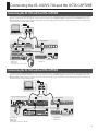
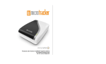
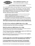
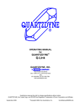
I/O Expansion by using the OCTA-CAPTURE with the VS-100/VS-700
Operating Requirements
You can use the OCTA-CAPTURE together with the VS-100 or VS-700 to expand the I/O. In order to expand the I/O, you must update the drivers and
system software.
VS-100:
System program version 1.50 or later
Driver version 2.0
VS-700:
System program version 1.30 or later
Windows driver version 2.0
Mac driver version 1.0
* There is no need to update the OCTA-CAPTURE.
Operating Requirements
NOTE
• The DIGITAL input connector is used in order to synchronize the VS-100/VS-700 with the OCTA-CAPTURE. You’ll need to obtain a coaxial cable
separately.
• This setup cannot be used at 192 kHz or higher.
• An internal hard disk drive that’s 7200 rpm or faster is required.
• In order to use this setup at 96 kHz or higher, a separate SATA hard disk drive is required as the audio recording destination. (This setup will not work
with a USB hard disk.)
• Depending on the application you’re using, the operating requirements may exceed those listed above.
Copyright © 2010 ROLAND CORPORATION
All rights reserved. No part of this publication may be reproduced in any form without the written permission of ROLAND CORPORATION.
Roland is a registered trademark of Roland Corporation in the United States and/or other countries.
2
Updating the VS-100/VS-700
Updating the VS-100
You’ll need to perform the following updates in order to use expanded
I/O functionality.
6. Click the [Scan SMF] (not required on a Mac), and verify that
the update files (_00001.mid–_00008.mid, end.mid) are
shown in the file list.
7. Click the [Send] button
• Update the driver to version 2.00 or later
File transmission will begin.
• Update the system program to version 1.50 or later
Transmission status is shown on the screen.
Updating the Driver
First, you need to download the driver from the Roland website.
The downloaded VS-100 driver version 2.00 is in a zip format archive
file. Right-click the file’s icon, choose “Extract All” from the menu that
appears, and extract the file as directed by the on-screen instructions.
In order to update the driver, you’ll first need to uninstall the old driver.
For details on the installation procedure, refer to the Readme.htm file
created when you extract the archive. You must read the Readme.htm
file before you install the driver.
Updating the System Program
Checking the version
Check the version of the VS-100’s system software.
When you power up the VS-100, the version of the current system
software is displayed in the lower right of the screen.
Version
Description
V1.30 or earlier
An update is required. Perform the update as
described below.
V1.50 or later
An update is not required.
Updating
1. Switch on the VS-100’s power, and before the
level meter screen appears, simultaneously
press the compressor/equalizer setting
button and the CH1 [COMP/EQ] button, and
continue holding down these buttons until
the following screen appears.
The current system software version will appear.
USB updater
0
V1.30/01CA (current version)
USB updater
12345 (Status of transfer)
USB Online
V1.30/01CA
When the transmission of the program has finished, the process of
writing the program into the VS-100 will begin.
NOTE
Do not power off the VS-100 until the update is complete, doing so
may damage the unit.
A screen like the following will appear.
USB updater
erase
USB Online
V1.20/01AF
USB updater
write
USB Online
V1.20/01AF
When the program has been updated successfully, a screen like the
following will appear.
USB updater
Update Successfully
Please Reboot
V1.20/01AF -> V1.50/01D4
Verify that the updated version is displayed.
This completes the update procedure.
8. Turn the power of the VS-100 off, then on again.
Make sure that the system software version shown in the lower right of
the screen is V1.50.
* If the update was unsuccessful, you can retry the process from step
1.
2. Use the USB cable to connect the VS-100 to
your computer.
When the USB connection is detected, the following
screen will appear.
USB updater
0
USB Online
V1.30/01CA
3. Double-click “UpdSMFJ” on your computer.
4. In the “MIDI Out Device” field, choose “CONTROL (VS-100).”
(on a Mac, choose “CONTROL.”)
5. Click the [Path] button (on a Mac, the [Select...] button),
and in SMF Path (on a Mac, SMF Folder), specify the folder
location that contains the update files (_00001.mid–_00008.
mid, end.mid).
3
Updating the VS-100/VS-700
Updating the VS-700
You’ll need to perform the following updates in order to use expanded
I/O functionality.
• Update the driver to version 2.00 or later. (Windows only)
• Update the system program to version 1.30 or later.
Updating the Driver
* The VS-700C driver is required for updating the system program
of the VS-700C console, so you must be sure to update the VS-700
driver and the VS-700C driver before you update the system
program.
* In order to update the driver for the VS-700C, you must set the
VS-700C to the standalone mode. For details, refer to p. 164 in the
owner's manual for the VS-700.
The downloaded file is a zip format archive. Right-click the file icon,
choose “Extract All” from the menu that appears, and extract the files
as directed by the on-screen instructions.
In order to update the drivers, you’ll first need to uninstall the old
drivers.
For details on the installation procedure, refer to the Readme.htm file
created when you extract the archive. You must read the Readme.htm
file before you install the drivers.
Updating the System Program
Checking the version of the VS-700C console
Check the version of the VS-700C console, VS-700 I/O CPU, VS-700 I/O
DSP, and VS-700 I/O FANTOM VS.
If the version number is 1.30 or later, the update is not required.
1. Switch off the VS-700C’s power.
2. On the rear panel, set switch #8 of the “SETTING” switches to
the “ON” position (upward); this selects Update mode.
Update mode
3. Switch on the VS-700C’s power.
4. The version is shown in the LCD display.
5. Switch the power off, then return switch #8 of the “SETTING”
switches on the rear panel to the “OFF” position (downward).
4
1. Install VS-700R I/O Editor
* VS-700R I/O Editor is an application that allows you to use VS-700R
I/O with applications other than SONAR. In this case, we’ll use it to
check the version.
Read the contents of Readme.htm, and install the software as directed.
* For details on using or uninstalling VS-700R I/O Editor, refer to
Readme.htm.
You must install both the VS-700 driver and the VS-700C driver.
Normal setting
Checking the version of the VS-700R I/O
2. Switch on the VS-700R’s power.
3. Use a USB cable to connect the VS-700R to your computer.
4. Start up VS-700R I/O Editor on your computer.
5. From the “Help” menu, open “VS-700R I/O Version.” If you’re
using Mac OS, choose the “VS-700R I/O Editor” menu
command “About VS-700R I/O.”
6. The “About VS-700R I/O” window will appear; check the
following version numbers.
• CPU
• DSP
• FANTOM VS
7. Click [OK] to close the “About VS-700R I/O” window.
8. Close VS-700R I/O Editor .
Updating the VS-100/VS-700
Updating the VS-700C console
* In order to update the VS-700C console, the VS-700C driver must be
installed in your computer.
* The update cannot be performed if the VS-700R is connected via
USB to your computer. Leave it disconnected.
1. Disconnect all USB cables from your computer (except those
connecting the keyboard and mouse).
2. As described in “Checking the version of the VS-700C
console,” put the VS-700C console in Update mode.
3. Use a USB cable to connect the VS-700C to your computer.
4. In the right side of the top panel, press the blinking [OK/
ENTER] button.
The indication in the LCD will change to “Erase.”
5. Press [OK/ENTER] once again.
The indication in the LCD will change to “Sure?”
6. Press [OK/ENTER] once again.
The indication in the LCD will change to “0%”.
7. On your computer, double-click “UpdSMFJ.”
8. As the “MIDI Out Device,” choose “CONSOLE (VS-700C)” (Mac
OS: “CONSOLE”).
9. Click the [Path] button (for Mac OS: the [Select...] button),
and in the SMF Path (Mac OS: SMF Folder), specify the
location that contains the update files (P00001.mid, P00002.
mid).
10. Click the [Scan SMF] button (not necessary on Mac OS), and
verify that the file list shows the update files (P00001.mid,
P00002.mid).
11. Click the [Send] button.
Data transmission will begin.
The indication in the LCD will change to “End.”
* The update will require approximately one minute.
* Never turn off the power while the update is in progress.
12. In UpdSMFJ’s Send SMF/Complete dialog box, click [OK].
Updating the VS-700R I/O CPU and DSP
* You can update the VS-700R I/O CPU and DSP simultaneously in a
single operation.
1. Disconnect all USB cables from your computer (except those
connecting the keyboard and mouse).
2. Make sure that the VS-700R’s power is switched off.
3. Disconnect everything from the VS-700R except for the
power cord.
4. In the VS-700R’s top panel, remove the expansion board
cover; then at the right side, turn SW1 “4” on, and turn the
other switches off.
5. In the left side of the VS-700R’s front panel, set the “SAMPLE
RATE” knob to “88.2 kHz.”
6. Switch on the VS-700R’s power.
7. Verify that the VS-700R’s front panel [USB], [CONSOLE], [MIDI
IN], and [MIDI OUT] indicators blink.
8. Return the VS-700R’s SW1 “4” to the “off” position.
9. Verify that the [USB] and [CONSOLE] indicators have gone
out, and that the [MIDI IN] and [MIDI OUT] indicators are lit.
10. Use a USB cable to connect the VS-700R to your computer.
11. Verify that the VS-700R’s [USB], [MIDI IN], and [MIDI OUT]
indicators are lit.
12. On your computer, double-click “UpdSMFJ.”
13. As the “MIDI Out Device,” choose “IO (VS-700)” (for Mac OS:
“VS-700 I/O”).
14. Click the [Path] button (for Mac OS, the [Select...] button),
and in the SMF Path (for Mac OS: SMF Folder) field, specify
the location of the update files (_00001.mid, end.mid).
15. Click the [Scan SMF] button (not necessary on Mac OS), and
verify that the update files (_00001.mid, end.mid) are shown
in the file list.
16. Click the [Send] button.
13. In UpdSMFJ, click [Exit] (for Mac OS: [QUIT]) to close
UpdSMFJ.
Data transmission will begin, and the VS-700R’s [MIDI IN] indicator will
blink.
14. Turn off the power, wait one or two seconds, and then turn
the power on again.
When the VS-700R’s [MIDI IN] and [MIDI OUT] indicator are both
blinking, the update is complete.
Verify that the version is shown as Version: 1.30.
15. Turn off the power, then return switch #8 of the “SETTING”
switches on the rear panel to the “OFF” position (downward).
* The update will require approximately two minutes.
* Never turn off the power while the update is in progress.
17. In UpdSMFJ’s Send SMF/Complete dialog box, click [OK].
18. In UpdSMFJ, click [Exit] (for Mac OS: [QUIT]) to close
UpdSMFJ.
19. Switch off the VS-700R’s power.
20. Reattach the expansion cover. If necessary, return the
“SAMPLE RATE” knob to the appropriate setting for your
system.
21. Switch on the VS-700R’s power once again.
22. Start up VS-700R I/O Editor and verify that the version is
1.30.
5
Updating the VS-100/VS-700
Updating the VS-700R I/O FANTOM VS
1. Disconnect all USB cables from your computer (except those
connecting the keyboard and mouse).
2. Make sure that the VS-700R’s power is switched off.
3. Disconnect everything from the VS-700R except for the
power cord.
4. In the VS-700R’s top panel, remove the expansion cover;
then at the right side, turn SW1 “4” on, and turn the other
switches off.
5. In the left side of the VS-700R’s front panel, set the “SAMPLE
RATE” knob to “192 kHz.”
6. Switch on the VS-700R’s power.
7. Verify that the VS-700R’s front panel [USB], [CONSOLE], [MIDI
IN], and [MIDI OUT] indicators blink.
8. Return the VS-700R’s SW1 “4” to the “off” position.
9. Verify that the indicators that were blinking in step 6 have
now gone out.
10. Use a USB cable to connect the VS-700R to your computer.
11. Verify that the VS-700R’s [USB] and [MIDI OUT] indicators are
both blinking.
12. On your computer, double-click “UpdSMFJ.”
13. As the “MIDI Out Device,” choose “FANTOM VS (VS-700)” (for
Mac OS: “FANTOM VS”).
14. Click the [Path] button (for Mac OS, the [Select...] button),
and in the SMF Path (for Mac OS, the SMF Folder) indication,
specify the location of the update file (FantomVSUpdate.
mid).
15. Click the [Scan SMF] button (not necessary on Mac OS), and
verify that the update file (FantomVSUpdate.mid) is shown
in the file list.
16. Click the [Send] button.
Data transmission will begin, and the VS-700R’s [MIDI IN] indicator will
blink.
When the VS-700R’s [MIDI IN] and [MIDI OUT] indicators are both
blinking, the update is complete.
* The update will require approximately three minutes.
* Never turn off the power while the update is in progress.
17. In UpdSMFJ’s Send SMF/Complete dialog box, click [OK].
18. In UpdSMFJ, click [Exit] (for Mac OS: [QUIT]) to close
UpdSMFJ.
19. Switch off the VS-700R’s power.
20. Reattach the expansion board cover. If necessary, return the
“SAMPLE RATE” knob to the appropriate setting for your
system.
21. Switch on the VS-700R’s power once again.
22. Start up VS-700R I/O Editor and verify that the version is
1.30.
6
Connecting the VS-100/VS-700 and the OCTA-CAPTURE
Connecting the VS-100 and the OCTA-CAPTURE
You’ll be able to use the OCTA-CAPTURE and VS-100 as a 18-in/16-out (of these, 2 IN/2 OUT are used for synchronization) audio interface with ASIO on
Windows or with Core Audio on Mac OS X. In order to connect two the VS-100 and OCTA-CAPTURE, you must turn on the VS EXPAND setting of the
OCTA-CAPTURE, and set both units to digitally synchronize at the same sampling frequency. Before you start making settings, disconnect both units
from the computer and turn off their power.
7 8
7
VS-100
1
OCTA-CAPTURE EXP
6
2
6
COAXIAL OUT (9/10)
COAXIAL IN (7/8)
COAXIAL CABLE
9
4 5
DIGITAL: AUTO
SAMPLE FREQ:
Same settings as the OCTA-CAPTURE
3
VS EXPAND: ON
Connecting the VS-700 and the OCTA-CAPTURE
You’ll be able to use the OCTA-CAPTURE and VS-700 as a 29-in/34-out (of these, 2 IN/2 OUT are used for synchronization) audio interface with ASIO on
Windows or with Core Audio on Mac OS X. In order to connect two the VS-700 and OCTA-CAPTURE, you must turn on the VS EXPAND setting of the
OCTA-CAPTURE, and set both units to digitally synchronize at the same sampling frequency. Before you start making settings, disconnect both units
from the computer and turn off their power.
7 8
7
Lower right of VS-700C front panel
6
VS-700R rear
OCTA-CAPTURE EXP
6
9
COAXIAL OUT (9/10)
COAXIAL IN (9/10)
COAXIAL CABLE
2 VS-700R front
VS EXPAND: OFF
DIGITAL: AUTO
SAMPLE FREQ:
Same settings as the OCTA-CAPTURE
4 5
1
3
VS EXPAND: ON
DIGITAL: AUTO
7
Connecting the VS-100/VS-700 and the OCTA-CAPTURE
1. Switch on the power to the VS-100/VS-700.
The OCTA-CAPTURE unit will be the timing master.
2. Specify the sampling frequency
(VS-100 Owner’s manual p. 52, VS-700 Owner’s manual p. 80)
* When using two units, they cannot be used with the 192 kHz setting.
3. Switch on the power to the OCTA-CAPTURE.
4. In the Utility section on the OCTA-CAPTURE, turn VS-EXPAND
on (OCTA-CAPTURE Owner’s manual p. 60).
5. Set the OCTA-CAPTURE to the same sampling frequency as
the VS-100/VS-700 (OCTA-CAPTURE Owner’s manual p. 68).
6. In order to digitally synchronize the two units, use a coaxial
cable to connect the OCTA-CAPTURE’s COAXIAL OUT (9/10)
to the VS-100/VS-700’s COAXIAL IN (9/10).
* If the Utility section’s DIGITAL setting is turned off, the sampling
frequency will not switch. Change the VS-100’s DIGITAL setting to
“AUTO” (VS-100 Owner’s manual p. 55)
7. Connect the VS-100/VS-700 and the OCTA-CAPTURE to the
computer.
Connect the two USB cables to USB ports that are near each other.
Windows 7/Windows Vista users
If “USB controller does not match” is shown:
Connect the VS-100/VS-700 or the OCTA-CAPTURE to a different USB
port, and keep trying other USB ports until the indication is “OK” or
“Sampling frequency does not match.”
* Alternatively, you can ensure that the VS-100/VS-700 and the OCTACAPTURE are connected to the same USB controller by connecting
them both to a USB 2.0 compliant hub.
If “Sampling frequency does not match” is shown:
Disconnect both USB cables from the computer, turn off the power
of the first unit, and start again from step 4. Connect each OCTACAPTURE unit to the same USB controller.
If VS EXPAND is grayed out:
Disconnect both USB cables from the computer, turn off the power of
the VS-100/VS-700 and the OCTA-CAPTURE units, and start again from
step 1.
Mac OS X users
Make “MIDI Input/Output Device Settings” (p. 25) on p. 25 of the
OCTA-CAPTURE Owner’s Manual for the OCTA-CAPTURE . In step 5,
enter the following names.
The driver will be installed automatically when you connect the
OCTA-CAPTURE. Please wait.
New Device
Device Name
Windows XP users
First [new external device]
EXP MIDI
After you’ve made the connection, follow steps 10 through 13 on p. 20
of the OCTA-CAPTURE Owner’s Manual to install the driver.
Second [new external device]
EXP CTRL
Mac OS X 10.5.8 or earlier
8. The procedure will differ depending on your system.
Proceed as follows.
Windows users
If you’re using Windows,
the two units must be
connected to the same USB
controller. In the Windows
control panel, double-click
the VS-100/VS-700 icon
to open the VS-100/
VS-700 control panel driver
settings. Make sure that
“OK” was indicated for the
VS EXPAND item.
1.
After making connections, start up “Audio MIDI Setup”
(/Applications/Utilities).
2.
From the “Audio” menu, choose “Open Aggregate Device
Editor.”
3.
The device settings dialog box will appear. Click the [+] button
to add an aggregate device.
Change the device set name to “VS-100 EXPANDED” or “VS-700
EXPANDED.”
If this does not indicate
“OK,” proceed as directed
below.
4.
Add a check mark to “VS-100”/ “VS-700”and then to “OCTACAPTURE EXP.”
5.
In the clock field, choose “OCTA-CAPTURE EXP.”
6.
If a check mark has been placed in the Resample field, clear the
check mark.
7.
Click “Finish” to close the dialog box.
Mac OS X 10.6 or later
1.
After making connections, start up “Audio MIDI Setup”
(/Applications/Utilities).
2.
Click the [+] button.
3.
“Aggregate Device” will appear in the list; double-click it and
edit the name.
(A screen shot for the VS-100 is shown here.)
Change the device set name to “VS-100 EXPANDED” or “VS-700
EXPANDED.”
4.
From the audio devices at the right, add a check mark to “Use”
for “VS-100”, “VS-700”, and then for “OCTA-CAPTURE EXP.”
5.
In the clock source field, choose “OCTA-CAPTURE EXP.”
6.
If a check mark has been placed in the Resample field, clear the
check mark.
9. Connect your headphones to the PHONES jack of the VS-100
or the VS-700 unit.
For Mac OS X, refer to “Core Audio device ports and input channel
numbers” (p. 13)
8
Connecting the VS-100/VS-700 and the OCTA-CAPTURE
Settings for monitoring through headphones
1. Start up the OCTA-CAPTURE control panel.
2. In the lower left of the screen, click the [OCTA-CAPTURE EXP]
button.
Setting the sampling frequency
1. Disconnect the coaxial cable that connects the VS-100/
VS-700 and the OCTA-CAPTURE units.
2. Disconnect the two USB cables from the computer.
3. Change the sampling frequency of the two units.
Set both units to the same sampling frequency.
4. In order to digitally synchronize the two units, use a
coaxial cable to connect the OCTA-CAPTURE’s COAXIAL
OUT jack to the VS-100/VS-700’s COAXIAL IN jack.
The state of the OCTA-CAPTURE will be shown.
3. In the upper right of the screen, click the [PATCHBAY] button.
5. Connect each unit’s USB cable to the computer.
* You’ll need to turn the VS-700’s power on once again.
The patch bay screen will appear.
4. In the OUTPUT 9–10 field, choose “DIRECT MIX A.”
5. Click the [Close] button to close the patch bay screen.
For the VS-100
You can use COAX (7/8) to control the volume. Set the
volume at an appropriate level.
All signals being input to the OCTA-CAPTURE will be
output from the PHONES jack of the VS-100/VS-700.
For the VS-700
Using VS-700 I/O Editor or the VS-700 Control Surface plug-in, set
DIGITAL1 INPUT SOURCE to COAXIAL IN, and set SYNC SOURCE to
DIGITAL1. For details, refer to the online manual.
9
Appendix
Input/Output Devices
VS-100 + OCTA-CAPTURE
VS-100
Input Device
Output Device
IN 1-2
IN 3-4
VS-100
DIGITAL
IN 5-6
OUT 1-2
OUT 3-4
VS-100
OUT 5-6
IN 7-8
MAIN
–
–
–
Used when synchronizing.
OCTA-CAPTURE
Input Device
Output Device
IN 1-2
OUT 1-2
IN 3-4
OCTA-CAPTURE EXP
IN 5-6
OUT 3-4
OCTA-CAPTURE EXP
IN 7-8
OUT 7-8
IN 9-10
MAIN
OUT 5-6
OUT 9-10
–
–
VS-700 + OCTA-CAPTURE
VS-700
Input Device
VS-700
Output Device
FANTOM VS (VS-700)
MAIN (VS-700)
ARX (VS-700)
SUB (VS-700)
AUX (VS-700)
1-2 (VS-700)
1-2 (VS-700)
3-4 (VS-700)
3-4 (VS-700)
5-6 (VS-700)
5-6 (VS-700)
7-8 (VS-700)
VS-700
7-8 (VS-700)
9-10 (VS-700)
DIGITAL1 (VS-700)
DIGITAL1 (VS-700)
DIGITAL2 1-2 (VS-700)
DIGITAL2 1-2 (VS-700)
DIGITAL2 3-4 (VS-700)
DIGITAL2 3-4 (VS-700)
DIGITAL2 5-6 (VS-700)
DIGITAL2 5-6 (VS-700)
DIGITAL2 7-8 (VS-700)
DIGITAL2 7-8 (VS-700)
Used when synchronizing.
OCTA-CAPTURE
Input Device
Output Device
IN 1-2
OUT 1-2
IN 3-4
OCTA-CAPTURE EXP
IN 5-6
OUT 3-4
OCTA-CAPTURE EXP
IN 7-8
OUT 7-8
IN 9-10
MAIN
10
OUT 5-6
OUT 9-10
–
–
Appendix
Port Names for the VS-100 and OCTA-CAPTURE (VS EXPAND)
ASIO input port names
Device
VS-100
OCTA-CAPTURE
(VS Expand: ON)
Input
Output
IN 1-2
OUT 1-2
IN 3-4
OUT 3-4
IN 5-6
OUT 5-6
DIGITAL
–
MAIN
–
EXP IN 1-2
EXP OUT 1-2
EXP IN 3-4
EXP OUT 3-4
EXP IN 5-6
EXP OUT 5-6
EXP IN 7-8
EXP OUT 7-8
EXP IN 9-10
EXP OUT 9-10
EXP MAIN
–
Core Audio device ports and input channel numbers
Device
VS-100
OCTA-CAPTURE
(VS Expand: ON)
Port
Core Audio channel number
IN 1-2
1, 2
IN 3-4
3, 4
IN 5-6
5, 6
DIGITAL
7, 8
MAIN
9, 10
IN 1-2
11, 12
IN 3-4
13, 14
IN 5-6
15, 16
IN 7-8
17, 18
IN 9-10
19, 20
MAIN
21, 22
Core Audio device ports and output channel numbers
Device
VS-100
OCTA-CAPTURE
(VS Expand: ON)
Port
Core Audio channel number
OUT 1-2
1, 2
OUT 3-4
3, 4
OUT 5-6
5, 6
OUT 1-2
11, 12
OUT 3-4
13, 14
OUT 5-6
15, 16
OUT 7-8
17, 18
OUT 9-10
19, 20
11
Appendix
Port Names for the VS-700 and OCTA-CAPTURE (VS EXPAND)
ASIO input port names
Device
VS-700
OCTA-CAPTURE
(VS Expand: ON)
Port
44.1/48 kHz
FANTOM VS
√
96 kHz
√
ARX
√
√
AUX
√
√
IN 1-2
√
√
IN 3-4
√
√
IN 5-6
√
√
IN 7-8
√
√
DIGITAL1
√
√
DIGITAL2 1-2
√
√
DIGITAL2 3-4
√
√
DIGITAL2 5-6
√
–
DIGITAL2 7-8
√
–
EXP IN 1-2
√
EXP IN 3-4
√
EXP IN 5-6
√
EXP IN 7-8
√
EXP IN 9-10
√
EXP MAIN
√
ASIO output port names
Device
VS-700
OCTA-CAPTURE
(VS Expand: ON)
12
Port
44.1/48 kHz
96 kHz
MAIN
√
√
SUB
√
√
OUT 1-2
√
√
OUT 3-4
√
√
OUT 5-6
√
√
OUT 7-8
√
√
OUT 9-10
√
√
√
DIGITAL1
√
DIGITAL2 1-2
√
√
DIGITAL2 3-4
√
√
DIGITAL2 5-6
√
-
DIGITAL2 7-8
√
-
EXP OUT 1-2
√
EXP OUT 3-4
√
EXP OUT 5-6
√
EXP OUT 7-8
√
EXP OUT 9-10
√
Appendix
Core Audio device ports and input channel numbers
Device
VS-700
OCTA-CAPTURE
(VS Expand: ON)
Port
Core Audio channel number
44.1/48 kHz
96 kHz
FANTOM VS
1, 2
1, 2
ARX
3, 4
3, 4
AUX
5, 6
5, 6
IN 1-2
7, 8
7, 8
IN 3-4
9, 10
9, 10
IN 5-6
11, 12
11, 12
IN 7-8
13, 14
13, 14
DIGITAL1
15, 16
15, 16
DIGITAL2 1-2
17, 18
17, 18
DIGITAL2 3-4
19, 20
19, 20
DIGITAL2 5-6
21, 22
–
DIGITAL2 7-8
23, 24
–
IN 1-2
25, 26
21, 22
IN 3-4
27, 28
23, 24
IN 5-6
29, 30
25, 26
IN 7-8
31, 32
27, 28
IN 9-10
33, 34
29, 30
MAIN
35, 36
31, 32
Core Audio device ports and output channel numbers
Device
VS-700
OCTA-CAPTURE
(VS Expand: ON)
Port
Core Audio channel number
44.1/48 kHz
96 kHz
MAIN
1, 2
1, 2
SUB
3, 4
3, 4
OUT 1-2
5, 6
5, 6
OUT 3-4
7, 8
7, 8
OUT 5-6
9, 10
9, 10
OUT 7-8
11, 12
11, 12
OUT 9-10
13, 14
13, 14
DIGITAL1
15, 16
15, 16
DIGITAL2 1-2
17, 18
17, 18
DIGITAL2 3-4
19, 20
19, 20
DIGITAL2 5-6
21, 22
–
DIGITAL2 7-8
23, 24
–
OUT 1-2
25, 26
21, 22
OUT 3-4
27, 28
23, 24
OUT 5-6
29, 30
25, 26
OUT 7-8
31, 32
27, 28
OUT 9-10
33, 34
29, 30
13
Appendix
Troubleshooting
Problem
Cause
Can’t sync the VS-700 and the OCTACAPTURE.
Did you use VS-700 I/O Editor or the Control Surface plug-in to set DIGITAL 1 INPUT SOURCE to COAXIAL IN, and set SYNC to
DIGITAL1?
Have you connected the coaxial cable to the VS-700’s COAXIAL IN?
Can’t monitor the OCTA-CAPTURE’s output
through headphones.
Did you make patchbay settings from the OCTA-CAPTURE’s control panel?
When updating the VS-700’s system
program, the input indicator blinked
when you connected the USB cable to
your computer, and the update could not
be performed.
After powering up the VS-700, did you return the SW1 “4” switch to the “off” position?
You performed the VS-700C console
update as directed by the manual, but it
was not successful.
Could a device other than the VS-700C be connected to the computer?
If the VS-700R is connected to your computer when updating the VS-700C, updating the VS-700C will not be successful.
2PS
14