1
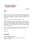
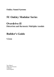
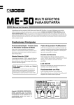
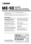
Thank you, and congratulations on your choice of BOSS OD-20 Overdrive/Distortion.
Before using this unit, carefully read the sections entitled: “USING THE UNIT SAFELY”
and “IMPORTANT NOTES” (separate sheet).
These sections provide important information concerning the proper operation of the unit.
Additionally, in order to feel assured that you have gained a good grasp of every feature
provided by your new unit, this manual should be read in its entirety. The manual should be
saved and kept on hand as a convenient reference.
Main Features
● Thanks to COSM technology, this distortion pedal delivers some of the most powerful
distortion you’ve ever heard. You get 22 different kinds of distortion sound, from vintage
classics to new, original sounds.
● Features ATTACK SHAPE for changing the picking expression, and a HEAVY OCTAVE
feature, which produces a fat octave sound, allowing you to create an even wider variety of
sounds.
● With four Memories plus Manual, you can use the pedal to switch through a total of five
sounds.
● Built-in Amp Control feature makes it possible to switch amp channels and perform other
controls that make your setup even more powerful when combined with an amp.
Copyright © 2001 BOSS CORPORATION
All rights reserved. No part of this publication may
be reproduced in any form without the written
permission of BOSS CORPORATION.
Installing Batteries
Batteries are supplied with the unit. The life of these batteries may be limited,
however, since their primary purpose was to enable testing.
Insert the included batteries as shown in figure, being careful to orient the batteries
correctly.
fig.02
• When turning the unit upside-down, get a bunch of newspapers or magazines, and
place them under the four corners or at both ends to prevent damage to the
buttons and controls. Also, you should try to orient the unit so no buttons or
controls get damaged.
• When turning the unit upside-down, handle with care to avoid dropping it, or
allowing it to fall or tip over.
• Make sure the “+” and “–” ends of the batteries are oriented correctly.
• When the batteries run down, the POWER indicator gets dim. If this happens,
replace with new batteries.
• When replacing the batteries, use six AA type.
• Avoid using new batteries together with used ones. In addition, avoid mixing
different types of batteries. Doing so can result in fluid leakage.
• Battery life can vary depending on battery type.
Continuous usage time under battery power is about 20 hours with
alkaline batteries and about 8 hours with carbon batteries. (This may
vary according to usage conditions.)
2
Making the Connections
• When the unit is running on battery power, the power comes on when you insert
the connector plug into the INPUT jack.
• The use of an AC adaptor is recommended as the unit’s power consumption is
relatively high. Should you prefer to use batteries, please use the alkaline type.
• Noise may be produced if wireless communications devices, such as cell phones,
are operated in the vicinity of this unit. Such noise could occur when receiving or
initiating a call, or while conversing. Should you experience such problems, you
should relocate such wireless devices so they are at a greater distance from this
unit, or switch them off.
• Use a cable from Roland to make the connection. If using some other make of
connection cable, please note the following precautions.
• Some connection cables contain resistors. Do not use cables that incorporate
resistors for connecting to this unit. The use of such cables can cause the sound
level to be extremely low, or impossible to hear. For information on cable
specifications, contact the manufacturer of the cable.
• To prevent malfunction and/or damage to speakers or other devices, always turn
down the volume, and turn off the power on all devices before making any
connections.
• If there are batteries in the unit while an AC adaptor is being used, normal
operation will continue should the line voltage be interrupted (power blackout or
power cord disconnection).
• Once the connections have been completed, turn on power to your various devices
in the order specified. By turning on devices in the wrong order, you risk causing
malfunction and/or damage to speakers and other devices.
When powering up:
Turn on the power to your guitar amp last.
When powering down: Turn off the power to your guitar amp first.
• Always make sure to have the volume level turned down before switching on
power. Even with the volume all the way down, you may still hear some sound
when the power is switched on, but this is normal, and does not indicate a
malfunction.
• When operating on battery power only, the unit’s indicator will become dim when
battery power gets too low. Replace the battery as soon as possible.
3
Making the Connections
Connecting to the Guitar Amp
fig.03
AC Adaptor
PSA-series
(option)
Electric
Guitar
Headphones
Guitar Amplifier
With a standard guitar amp, it may be a good idea to set all the tone
controls (BASS, MIDDLE, and TREBLE) to their central positions first,
then adjust from there.
Connecting to an MTR
Simulator) or Mixer
(with No Internal Guitar Amp
fig.04
AC Adaptor
PSA-series
(option)
Electric
Guitar
MTR
4
Mixer
Operation
“MANUAL” and “EFFECT ON” are selected when the power is turned on.
EFFECT ON/OFF Pedal Operation
fig.05
When at “ON”
← Lit
When at “OFF”
← Not lit
Each press of the EFFECT ON/OFF pedal
switches effects on or off.
When effects are off, the sound coming in
through the INPUT jack is output unchanged.
5
Operation
MANUAL/MEMORY Pedal Operation
The Pedal mode (1–3) changes the function of the MANUAL/MEMORY pedal (or
the MANUAL/MEMORY pedal used with the EFFECT ON/OFF pedal). Use the
most appropriate setting for your particular application.
At the factory settings, Pedal mode is set to “1.”
When changing the Pedal mode settings, refer to p. 7.
Pedal mode: 1
Pressing the MANUAL/MEMORY pedal cycles you through a series of selections,
in this order: MANUAL → MEMORY 1 → MEMORY 2 → MEMORY 3 →
MEMORY 4 → MANUAL. This convenient feature makes it easier to switch
memories in songs in which multiple memories are used.
fig.06
MEMORY 1
MEMORY 2
MEMORY 3
MEMORY 4
Pedal mode: 2
fig.07
Pressing the MANUAL/MEMORY pedal switches you
between MANUAL and the selected memory (shown by the
lit indicator). This is convenient when you want to switch
two effect sounds (MANUAL and MEMORY) instantly.
MEMORY
Pedal mode: 3
fig.08
Pressing the MANUAL/MEMORY pedal toggles you
between MANUAL and the selected memory (shown by
the lit indicator).
MEMORY
You can also select among Memories 1–4 by pressing the MANUAL/MEMORY pedal
and EFFECT ON/OFF pedal simultaneously. This is convenient for both switching two
effect sounds (MANUAL and MEMORY), and switching memories between songs.
fig.09
MEMORY 1
6
MEMORY 2
MEMORY 3
MEMORY 4
Operation
Changing the Pedal Mode Settings
Use the following procedure when changing the Pedal mode settings.
* The pedal mode setting is stored in memory when the power is switched off.
1. Switch off the power.
• When running on battery power:
Disconnect the connection plug from the INPUT jack.
• When running on power from an AC adaptor:
Disconnect the plug from the AC ADAPTOR jack.
2. While holding down the MEMORY SELECT button, switch on the power.
• When running on battery power:
Insert the connection plug into the INPUT jack.
• When running on power from an AC adaptor:
Insert the AC adaptor plug into the AC ADAPTOR jack.
When you release the button, the MANUAL and MEMORY indicators light.
At the same time, the Memory number indicator corresponding to the settings of
the current pedal mode blinks.
3. Set the pedal mode (1–3) pressing the MEMORY SELECT button.
Pedal mode 1: MEMORY 1 indicator blinks.
Pedal mode 2: MEMORY 2 indicator blinks.
Pedal mode 3: MEMORY 3 indicator blinks.
4. Press the WRITE button.
After the MEMORY Number indicator begins blinking rapidly, the setting is stored
in memory and the unit returns to its ordinary state.
* To cancel the setting change, operate the EFFECT ON/OFF pedal or the MANUAL/
MEMORY pedal before pressing the MEMORY WRITE button. The unit will return to
its ordinary state.
Pedal
Mode
EFFECT ON/OFF EFFECT ON/OFF Pedal
MANUAL/MEMORY Pedal
+
Pedal
MANUAL/MEMORY Pedal
1
effect on/off
2
effect on/off
3
effect on/off
–
Switches
MANUAL/MEMORY 1/2/3/4
–
Switches MANUAL/MEMORY
Selects from MEMORY 1–4 Switches MANUAL/MEMORY
7
Operation
Panel Operation
In order to follow along with the instructions given here, you should start out by
having effects switched ON (press the EFFECT ON/OFF pedal and confirm that
the EFFECT ON/OFF indicator has lighted), and press the MANUAL/MEMORY
pedal to switch MANUAL (MANUAL indicator has lighted).
fig.10
2
3
5
4
1
1. Select the distortion type with the TYPE knob and the VARIATION button.
2. Turn the DRIVE knob to adjust the amount of distortion.
3. Turn the TONE and BOTTOM knobs to adjust the tone.
4. Turn the ATTACK SHAPE and HEAVY OCTAVE knobs to adjust effects other
than distortion.
5. Adjust the volume with the LEVEL knob.
It may be a good idea to switch on or off using the EFFECT ON/OFF
pedal and adjust the volume to about the same level.
8
Operation
Using Guitar Amp Channel Switching
(Amp Control)
By connecting your guitar amp’s channel switching jack to the OD-20’s AMP CTRL
jack, you can then use the AMP CTRL button to switch the amp channel.
This combining of the OD-20 and the amp channels allows you to get an even
wider variety of distortion sounds.
fig.11
Open
Lit
Guitar Amplifier
OD-20
(amp’s channel switching jack) (AMP CTRL jack)
Short
Off
Guitar Amplifier
OD-20
(amp’s channel switching jack) (AMP CTRL jack)
* To determine how the amp channels are switched when the circuit is open and shorted, refer
to the amp owner’s manual, or actually confirm the sounds by operating the amp.
* You can set the Amp Control independently of the effect On/Off settings.
* You can store separate Amp Control settings to each memory. For more on this procedure,
refer to “Storing Settings (Write Operation)” (p. 10).
With Amp Control, not only can you switch amp channels, you can also
use it to switch the amp’s effects on and off, like a foot switch
controller.
9
Operation
Storing Settings (Write Operation)
Storing the “MANUAL” Sound in Memory
Do not switch off the power while a write operation is in progress.
1. Create the sound you want when set to “MANUAL.”
2. Press the MEMORY WRITE button.
The MEMORY indicator and the indicator for the currently selected memory blink,
and the OD-20 is put into write standby.
fig.12
Write standby
Blink
Blink
3. Press the MEMORY SELECT button to select the memory (number) to which
you want to store the sound.
The indicator for the selected MEMORY number blinks.
fig.13
Blink
10
Blink
Operation
4. Press the MEMORY WRITE button.
The write operation finishes after the MEMORY indicator and the indicator for the
write-destination memory have begun to blink more rapidly.
fig.14
Blink
Writing
Blink rapidly
Write finished
Lit
* To cancel the write operation, operate a knob or the MANUAL/MEMORY pedal before
you press the WRITE button.
11
Operation
Changing and Storing the “MEMORY” Sound
Do not switch off the power while a write operation is in progress.
1. Press the MANUAL/MEMORY pedal or the MEMORY SELECT button to
change to the “MEMORY” sound.
2. Operate the knobs to change the sound.
* To avoid sudden inadvertent changes in sound, the DRIVE, BOTTOM, TONE, LEVEL,
ATTACK SHAPE, and HEAVY OCTAVE knobs are designed so that the setting does not
change unless the knob is first turned as far as the stored setting value. Once the position of
the knob matches the setting value stored in memory, the sound starts to change.
When a setting changes, the MEMORY indicator blinks automatically.
fig.15
Blink
3. Press the MEMORY WRITE button.
The MEMORY indicator and the indicator for the currently selected MEMORY
number start to blink, and the OD-20 is put into write standby.
fig.16
Lit
Write standby
Blink
12
Blink
Operation
4. Press the MEMORY SELECT button to select the memory (number) to which
you want to store the sound.
The indicator for the selected MEMORY number blinks.
fig.17
Blink
Blink
5. Press the MEMORY WRITE button.
The write operation finishes after the MEMORY indicator and the indicator for the
write-destination memory have begun to blink more rapidly.
fig.18
Blink
Writing
Blink rapidly
Write finished
Lit
* To cancel the write operation, operate a knob or the MANUAL/MEMORY pedal before
you press the WRITE button. And the OD-20 is returned to the status in effect in Step 2.
13
Part Names and Functions
Front Panel
fig.19
BOTTOM Knob
Adjusts the low frequency range. Turning the
knob to the left (counterclockwise) cuts the low
end more; the low frequencies are boosted as
the knob is turned to the right. Optimized for
the distortion selected with “TYPE.”
DRIVE Knob
TONE Knob
Adjusts the amount of distortion. Turning the
knob to the right (clockwise) creates a
stronger distortion and increases the volume.
Turning this all the way to the TURBO range
increases the effect even more.
Adjusts the tone. Turning the knob to
the left creates a milder sound; a
sharper sound is produced as the knob
is turned to the right. Optimized for the
distortion selected with “TYPE.”
LEVEL Knob
Adjusts the volume.
ATTACK SHAPE Knob
Changes the tone of the attack
portion. Turning the knob to the
left of the center position results
in a smoother tone; a tone with a
more prominent edge is created
when the knob is turned to the
right of center.
14
HEAVY OCTAVE Knob
Adds sound an octave below what
is performed by the guitar when
playing in the low registers.
Turning the knob to the right
raises the level of the octave
sound. Output of the octave
sound ceases when the knob is
turned completely to the left.
* No octave sound is added when
you play in the high-middle
registers.
Part Names and Functions
fig.20
TYPE Knob
VARIATION Button
Select the distortion type with the TYPE knob,
then press the VARIATION button to select the
variation. The button's indicator lights up when a
variation is selected.
“TYPE List” (p. 16)
MEMORY Number Indicator (1–4)
The indicator for the currently selected
MEMORY number (1–4) lights. The indicator
flashes while the OD-20 is in write standby;
the indicator flashes more rapidly while the
write operation is in progress.
AMP CTRL (amp control) Button
This switches the amp channel when you
have the guitar amp’s channel switching
jack connected to the OD-20’s AMP CTRL
jack.
MEMORY WRITE Button
Press this to store settings in
“MEMORY.”
MEMORY SELECT Button
Use this to select a Memory (1–4),
and to specify the write
destination when carrying out the
write procedure.
* When “1” is selected as the Pedal
mode (p. 6), you can switch between
“Manual” and “Memory (1–4).”
15
Part Names and Functions
TYPE List
* All product names mentioned in this document are trademarks or registered trademarks of
their respective owners.
Those companies are not affiliated with BOSS and have not licenced or authorized BOSS’s
OD-20. Their marks are used solely to identify the equipment whose sound is simulated by
BOSS’s OD-20.
Not lit
16
Lit
OD-1
Models the BOSS OD-1.
OD-2
Models the BOSS OD-2.
DS-1
Models the BOSS DS-1.
BD-2
Models the BOSS BD-2.
MT-2
Models the BOSS MT-2.
HM-2
Models the BOSS HM-2.
LEAD
OD-20 original distortion.
Produces a distortion sound
with both the smoothness of
an overdrive along with a
distortion’s depth.
BOOST
OD-20 original booster.
STACK
OD-20 original distortion.
A fat sound with an added
element of a stack amp’s
distortion.
CRUNCH OD-20 original distortion.
A lustrous crunch sound with
an added element of amp
distortion.
LOUD
OD-20 original distortion.
A heavy distortion with a
boosted low end.
METAL
OD-20 original distortion.
An intense, radical distortion
sound.
TModels the Ibanez TS-808
SCREAM TUBESCREAMER.
FULL-D
Models the Fulltone FULLDRIVE 2.
DST+
Models the MXR
DISTORTION+.
CENTA
OD
Models the KLON CENTAUR.
GUV DS
Models the Marshall
GOV’NOR.
P-RAT
Models the Proco RAT.
* When set to P-RAT, turning
the TONE knob to the right
cuts the high frequencies.
R-MAN
Models the ROCKMAN.
MUFF
FUZZ
Models the Electro-Harmonix
Big Muff π.
FACE
Models the FUZZFACE.
OCT
FUZZ
Models the ACETONE FUZZ.
Part Names and Functions
fig.21
POWER Indicator
This lights up when the power is on.
If this gets dim or fails to light up when the
unit is running on battery power, it means
that the batteries are depleted.
Replace promptly with fresh batteries.
EFFECT ON/OFF
Indicator
This lights up when effects are
on.
EFFECT ON/OFF Pedal
MANUAL/MEMORY Pedal
Each press of the pedal switches the
effects on or off.
You can press the pedal to switch
between “Manual,” where the sound is
output according to the settings of the
panel knobs and switches, and your
selection of a “Memory” (1–4), which
contain stored settings.
MANUAL Indicator
This lights up when set to “MANUAL.”
MEMORY Indicator
This lights up when set to “MEMORY” (1–4).
This blinks when you turn a knob to change the value
of a setting, or put the OD-20 into write standby while
a memory is selected, and blinks rapidly while data is
being written.
When at “MANUAL”
* The Pedal mode (1–3) changes the function
of the MANUAL/MEMORY pedal (or the
MANUAL/MEMORY pedal used with
the EFFECT ON/OFF pedal). Use the
most appropriate setting for your
particular application. (p. 6)
When at “MEMORY”
← Lit
← Not lit
← Not lit
← Lit
17
Part Names and Functions
Rear Panel
fig.22
INPUT Jack
This is the input jack for connecting to the output
of an electric guitar or other instrument or effects
processor.
* The INPUT jack also doubles as the power switch
when the unit is running on battery power. The
power comes on when a plug is inserted into the
INPUT jack, and goes off when it is unplugged.
Unplug any connected cords when the unit is not in
use.
AC Adaptor Jack
This jack is for connecting an AC
adaptor (BOSS PSA-series, sold
separately). Using an AC adaptor
makes possible long performances
with no worry about batteries going
dead.
AMP CTRL (amp control) Jack
OUTPUT Jack
This jack is used when connecting to
remote jacks, such as a guitar amp's
channel switching jack.
This jack is for connection to a
guitar amp or another effects
processor.
LINE OUT/PHONES Jack
Headphones, or a multitrack recorder or mixer
that has no amp simulator can be connected to
this output jack.
18
Changing How Memory Numbers Are Indicated
Not only can you confirm the currently selected memory merely by checking the lit
MEMORY Number indicators, you can also change the pattern in which the
indicators light up. Select the pattern that provides the easiest way to check the
memory in any particular environment.
When using the OD-20 in dimly lit surroundings, you can confirm
memory numbers more easily by using the Lighting Pattern 2 setting.
Lighting Pattern 1 (Normal):
Only the indicator for the selected memory lights up (or blinks).
Lighting Pattern 2:
The number of indicators lighting up (or blinking) corresponds to the selected
memory number.
When MEMORY 1 is selected: Indicator 1 lights up.
When MEMORY 2 is selected: Indicators 1 and 2 light up.
When MEMORY 3 is selected: Indicators 1, 2, and 3 light up.
When MEMORY 4 is selected: Indicators 1, 2, 3, and 4 light up.
You can select the indicator lighting pattern by means of the following procedure.
1. Switch off the power.
• When running on battery power:
Disconnect the connection plug from the INPUT jack.
• When running on power from an AC adaptor:
Disconnect the plug from the AC ADAPTOR jack.
2. While holding down the MEMORY WRITE button and the MEMORY SELECT
button, switch on the power.
• When running on battery power:
Insert the connection plug into the INPUT jack.
• When running on power from an AC adaptor:
Insert the AC adaptor plug into the AC ADAPTOR jack.
When the button is released, either the No. 1 indicator alone blinks, or all
indicators from 1 through 4 blink.
3. Press the MEMORY SELECT button to set the MEMORY indicator lighting pattern.
Lighting Pattern 1: Indicator 1 alone blinks.
Lighting Pattern 2: Indicators 1–4 all blink.
4. Press the MEMORY WRITE button.
After the MEMORY Number indicator(s) begins blinking rapidly, the setting is
stored in memory and the unit returns to its ordinary state.
* To cancel the setting change, operate the EFFECT ON/OFF pedal or the MANUAL/MEMORY
pedal before pressing the MEMORY WRITE button. The unit will return to its ordinary state.
19
Returning Settings to Their Factory Defaults
You can restore the memories (1–4), pedal mode settings, and the MEMORY
Number Indication to their original factory values.
Memory
Settings
Memory 1 (p. 23)
LOUD
Memory 2 (p. 24)
LEAD
Memory 3 (p. 24)
OD-1
Memory 4 (p. 24)
STACK
Pedal Mode (p. 7)
1
(MANUAL → MEMORY 1 → MEMORY 2 →
MEMORY 3 → MEMORY 4 → MANUAL)
MEMORY Number
Indication (p. 19)
Lighting Pattern 1
(Only the indicator for the selected memory lights up.)
Carrying out the following procedure completely clears the content
currently stored in the memories (1–4).
1. Switch off the power.
• When running on battery power:
Disconnect the connection plug from the INPUT jack.
• When running on power from an AC adaptor:
Disconnect the plug from the AC ADAPTOR jack.
2. While holding down the WRITE button, switch on the power.
• When running on battery power:
Insert the connection plug into the INPUT jack.
• When running on power from an AC adaptor:
Insert the AC adaptor plug into the AC ADAPTOR jack.
When you release the button, the MEMORY Number indicators blink.
3. Press the MEMORY WRITE button.
After the MEMORY Number indicators begin blinking rapidly, the setting is stored
in memory and the unit returns to its ordinary state.
* To cancel the setting change, operate the EFFECT ON/OFF pedal or the MANUAL/
MEMORY pedal before pressing the MEMORY WRITE button. The unit will return to
its ordinary state.
20
Troubleshooting
The power doesn’t come on.
properly
● Is the guitar connected correctly to the
INPUT jack?
→ Check the connections again (p. 3–4).
● Is the amp’s channel switching jack
correctly connected to the OD-20’s AMP
CTRL jack?
→ Check the connections again.
* When running on batteries, the unit won't
switch on until a plug is inserted into the
INPUT jack. This helps conserve the batteries.
● Have the batteries run down?
→ Replace with fresh batteries (p. 2).
● Is the specified AC adaptor (PSA-series
sold separately) connected correctly?
→ Check the connections again (p. 3–4).
There is no sound/volume is too
low.
● Is the other equipment connected
correctly?
→ Check the connections again (p. 3–4).
● Is the volume turned down on the
connected guitar amp, effects processor,
or other device?
→ Check the settings on the connected
equipment (p. 3–4).
● Does the amp’s channel switch match
the polarity of the OD-20’s Amp
Control?
→ The OD-20’s Amp Control is shorted
when the indicator is off, and open when
the indicator is lit (p. 9).
Confirm how amp’s channels are
switched when the circuit is open or
shorted.
The volume level of the
instrument connected to INPUT
jack is too low.
● Could you be using a connection cable
that contains a resistor?
→ Use a connection cable that does not
contain a resistor.
Noise is produced.
● Is the guitar connected correctly to the
INPUT jack?
→ When you are using the AC adaptor, the
power comes on even when a connector is
not plugged into the INPUT jack. This
means that noise may be produced when
nothing is connected to the INPUT jack.
Make sure everything is connected
properly before switching on the power to
your equipment.
Cannot switch amp channels
21
Sample Settings
Crunch with mild amp distortion
fig.23
Lit
Overdrive with heavy distortion
fig.24
Lit
Fat distortion sound
fig.25
Not lit
22
Sample Settings
Fairly bright metal sound
fig.26
Lit
Radical fuzz
fig.27
Not lit
LOUD (Factory Default Memory 1)
fig.28
Not lit
23
Sample Settings
LEAD (Factory Default Memory 2)
fig.29
Not lit
OD-1 (Factory Default Memory 3)
fig.30
Not lit
STACK (Factory Default Memory 4)
fig.31
Not lit
24
Setting Memo
(
)
fig.32
Lit / Not lit
(
)
fig.32
Lit / Not lit
(
)
fig.32
Lit / Not lit
25
Specifications
OD-20: Overdrive/Distortion
Nominal Input Level
20 dBu
Input Impedance
1 MΩ
Nominal Output Level
Connectors
INPUT Jack
AMP CTRL (amp control) Jack
LINE OUT/PHONES Jack
OUTPUT Jack
AC Adaptor Jack (DC 9 V)
20 dBu
Power Supply
Output Impedance
DC 9 V: Dry Battery (R6/LR6 (AA) type) x 6
AC Adaptor
1 kΩ
Recommended Load Impedance
10 kΩ or greater
Dynamic Range
102 dB (IHF-A typ.)
Controls
EFFECT ON/OFF Pedal
MANUAL/MEMORY Pedal
DRIVE Knob
BOTTOM Knob
TONE Knob
LEVEL Knob
ATTACK SHAPE Knob
HEAVY OCTAVE Knob
TYPE Knob
VARIATION Button
AMP CTRL (amp control) Button
MEMORY WRITE Button
MEMORY SELECT Button
Indicators
POWER Indicator (serves also as battery check indicator)
EFFECT ON/OFF Indicator
MANUAL Indicator
MEMORY Indicator
VARIATION Indicator
AMP CTRL (amp control) Indicator
MEMORY Number Indicator (1–4)
26
Current Draw
85 mA (9 V max.)
* Expected battery life under continuous use:
Carbon: 8 hours
Alkaline: 20 hours
These figures will vary depending on the actual
conditions of use.
Dimensions
173 (W) x 158 (D) x 57 (H) mm
6-13/16 (W) x 6-1/4 (D) x 2-1/4 (H) inches
Weight
1.1 kg / 2 lbs 7 oz (including batteries)
Accessories
Owner’s Manual
Leaflet (“USING THE UNIT SAFELY,”
“IMPORTANT NOTES,” and “Information”)
Dry battery (LR6 (AA) type) x 6
* We recommend that alkaline batteries be used when
replacing the batteries.
Options
AC Adaptor (PSA-series)
* 0 dBu = 0.775 Vrms
* In the interest of product improvement, the
specifications and/or appearance of this unit are
subject to change without prior notice.
For EU Countries
This product complies with the requirements of European Directive 89/336/EEC.
For the USA
FEDERAL COMMUNICATIONS COMMISSION
RADIO FREQUENCY INTERFERENCE STATEMENT
This equipment has been tested and found to comply with the limits for a Class B digital device, pursuant to Part 15 of the
FCC Rules. These limits are designed to provide reasonable protection against harmful interference in a residential
installation. This equipment generates, uses, and can radiate radio frequency energy and, if not installed and used in
accordance with the instructions, may cause harmful interference to radio communications. However, there is no guarantee
that interference will not occur in a particular installation. If this equipment does cause harmful interference to radio or
television reception, which can be determined by turning the equipment off and on, the user is encouraged to try to correct the
interference by one or more of the following measures:
– Reorient or relocate the receiving antenna.
– Increase the separation between the equipment and receiver.
– Connect the equipment into an outlet on a circuit different from that to which the receiver is connected.
– Consult the dealer or an experienced radio/TV technician for help.
This device complies with Part 15 of the FCC Rules. Operation is subject to the following two conditions:
(1) This device may not cause harmful interference, and
(2) This device must accept any interference received, including interference that may cause undesired operation.
Unauthorized changes or modification to this system can void the users authority to operate this equipment.
This equipment requires shielded interface cables in order to meet FCC class B Limit.
For Canada
NOTICE
This Class B digital apparatus meets all requirements of the Canadian Interference-Causing Equipment Regulations.
AVIS
Cet appareil numérique de la classe B respecte toutes les exigences du Règlement sur le matériel brouilleur du Canada.
27
G6017351
’00-xx-xx-xxx