1
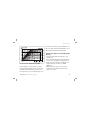
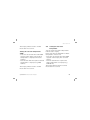
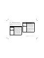
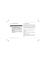
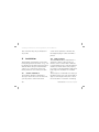
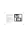
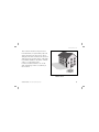
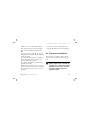
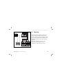
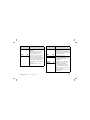
For the owner and the heating engineer
Operating and Installation Manual
VRC 400
Programmable weather compensator with separat HW time control
GB
Contents
Contents
Notes on the documentation . . . . .
Symbols used...........................................
Storage of the documents....................
4
4
4
Safety . . . . . . . . . . . . . . . . . . . . . . . .
5
Operating manual. . . . . . . . . . . . . . .
6
1
Control overview. . . . . . . . . . . .
6
2
Display overview. . . . . . . . . . . .
7
3
Description of the control . . . .
8
2
4 Operation. . . . . . . . . . . . . . . . . . 9
4.1 Setting the operating modes ...... 9
4.2 Setting the current day and
time ................................................... 12
4.3 Setting timer programmes .......... 13
4.4 Setting the room temperature ... 16
4.5 Setting the hot water
temperature .................................... 19
4.6 Activating special functions ........ 20
4.7 Info level........................................... 22
5
Vaillant warranty . . . . . . . . . . . 23
6
Recycling and disposal. . . . . . . 24
Operating manual and installation manual for VRC 400 weather compensator
Contents
Installation manual . . . . . . . . . . . . . 25
7
Information on installation
and operation . . . . . . . . . . . . . . 25
7.1 CE label............................................. 25
7.2 Intended use.................................... 25
8
Safety instructions and
regulations . . . . . . . . . . . . . . . . 26
8.1 Safety instructions ........................ 27
8.2 Regulations...................................... 27
9
9.1
9.2
9.3
Installation . . . . . . . . . . . . . . . .
Control installation ........................
Wall mounting .................................
Installing the VRC 693 outdoor
sensor ...............................................
28
28
28
10 Electrical installation. . . . . . . . 33
10.1 Connecting the weather
compensator ................................... 34
10.2 Connecting the outside sensor... 34
11
11.1
11.2
11.3
Start-up. . . . . . . . . . . . . . . . . . .
Installer level...................................
Service/diagnostic level................
Handing over to the owner..........
35
36
40
42
12
Technical data. . . . . . . . . . . . . . 43
13
Vaillant customer service . . . . 43
30
Operating manual and installation manual for VRC 400 weather compensator
3
Notes on the documentation
Notes on the documentation
The following information is intended to
help you throughout the entire documentation. Further documents apply in
combination with this installation and
operation manual.
We accept no liability for any damage
caused by failure to observe these
instructions.
Symbols used
Please observe the safety instructions in
this manual for the installation of the
control.
Danger
Immediate risk of serious injury
or death
• Symbol for a necessary task
Storage of the documents
Please pass on this operating and installation manual to the owner of the system
so that he can keep it available whenever it is required.
4
Operating manual and installation manual for VRC 400 weather compensator
Safety
Safety
The weather compensator must be
installed by a qualified engineer, who is
responsible for adhering to the existing
standards and regulations.
We accept no liability for any damage
caused by failure to observe these
instructions.
Operating manual and installation manual for VRC 400 weather compensator
5
1 Control overview
Operating manual
1
Control overview
1
2
Key
1 Display
2 Dial (turn and click)
I Info button
F Special functions button
P Programming button/installer level
Fig. 1.1 Control overview
6
Operating Manual for VRC 400 weather compensator
Display overview 2
2
Display overview
8
7
6
9
1
10
2
3
11
12
5
4
Fig. 2.1 Overview of display
Operating Manual for VRC 400 weather compensator
Key
1 Installer level and
service/diagnosis level (see 11.1)
2 Info level (see 4.7)
3 Circulation pump symbol
4 Time/temperature display
5 Days of the week
6 Actual temperature
7 Operating modes (see 4.1)
8 Special functions (see 4.6)
9 Setting timer programmes (see 4.3)
10 Boiler operation indicator
11 Hot water symbol
12 Heating circuit symbol
7
3 Description of the control
3
Description of the
control
The VRC 400 is a weather compensator
with a weekly programme for heating,
hot water and a circulation pump for
connecting to Vaillant boilers with an
eBus.
The VRC 400 enables you to set heating
programmes depending on the outside
temperature. In addition, you can select
special functions such as the party function, and control the timed operation of
hot water and a separate circulation
pump.
8
Operating Manual for VRC 400 weather compensator
Operation 4
4
Operation
The operating principle uses three buttons and a dial (Vaillant “Turn and Click”
operating concept).
The display normally shows the current
operating mode (e.g.
), or, if activated, the special function and the current room temperature, the day of the
week, the time and the symbol for
heating, hot water and/or the circulation pump, depending on which is
requested.
4.1
Setting the operating modes
Table 4.1 contains an overview of the
operating modes you can select.
The selected operating mode affects the
timer programmes both for heating and
for hot water and the circulation pump.
• When the weather compensator is in
normal display mode, press the dial
once – the symbol for the selected
mode flashes in the display.
• Turn the dial until the display shows
the operating mode you want.
The display switches back to normal
mode after five seconds.
Operating Manual for VRC 400 weather compensator
9
4 Operation
Symbol Meaning
Heating
Automatic:
According to the timer programmes set in the
weather compensator, the heating circuit switches
between heating mode and set-back mode .
The heating circuit symbol is displayed if a heating
requirement is detected.
Heating:
The heating circuit is operated according to the
room temperature, regardless of the programme set
on the controller.
The heating circuit symbol is displayed if a heating
requirement is detected.
Set-back:
The heating circuit is operated according to the
set-back temperature “ECO”, regardless of the programme set on the controller.
The heating circuit symbol is displayed if a heating
requirement is detected.
10
Meaning
Hot water/circulation pump
The hot water cylinder/circulation
pump mode switches between heating ON and OFF according to the
timer programme set on the controller. The hot water symbol and the
circulation pump symbol are shown
when the time window is active. If
there is a hot water request, the hot
water symbol flashes.
Operating Manual for VRC 400 weather compensator
Operation 4
Symbol Meaning
Heating
Meaning
Hot water/circulation pump
ECO:
According to the setted timer programmes, the
See the table on the left
heating circuit switches between heating mode
and OFF. The heating circuit is switched off in setback mode, provided the anti-frost function (activated when the outside temperature is below 3 °C) is
not active. The heating circuit symbol is displayed if
a heating requirement is detected or the anti-frost
function is active.
Off:
The heating circuit is off, provided that the frost
protection function (if the outside temperature is
below 3 °C) is not activated. If the frost protection
function is activated, the heating circuit symbol is
displayed.
The boiler is not heated up, regardless of the set timer programme. The
circulation pump is switched off.
The hot water and circulation pump
symbols are not displayed.
Table 4.1 Operating modes
Operating Manual for VRC 400 weather compensator
11
4 Operation
4.2
Setting the current day and time
To set the current day and time with the
display in normal mode, you must perform the following steps:
• Press the dial until a day of the week
starts flashing.
• Turn the dial until you see the current
day of the week.
MO = Monday
TU = Tuesday
WE = Wednesday
TH = Thursday
FR = Friday
SA = Saturday
SU = Sunday
12
• Press the dial. The hours start flashing.
• Turn the dial until you see the current
hour.
• Press the dial. The minutes start flashing.
• Turn the dial until you see the current
minute.
The display switches back to normal
mode after five seconds.
If the calendar is activated on the installer level (see 11.1), you can set the day,
month and year in the same way.
This allows automatic switching from winter to summer time.
Operating Manual for VRC 400 weather compensator
Operation 4
4.3 Setting timer programmes
The controller is equipped with a basic
program (Table 4.2).
Time
window
H1
H2
H3
H1
H2
H3
H1
H2
H3
Day/Block of
days
MO-FR
SA
SU
-
Start
time
6:00
7:30
-
End
time
22:00
23:30
-
-
-
7:30
-
22:00
-
You can adapt the default programmes
to suit your needs. There are six steps to
setting the times you want:
1. Press the programming button P
2. Select the timer programme (heating,
hot water or circulation pump)
3. Select the time window
4. Select the day or block of days
5. Set the start time
6. Set the end time
You can define three time windows for
each day.
When you press the P button the display
returns to basic mode.
Table 4.2 Default heating, hot water and circulation programmes
Operating Manual for VRC 400 weather compensator
13
4 Operation
The table below illustrates the individual
steps again, using the example of the hot
water timer programme.
If you want to change the timer programme for heating or the circulation
pump, after pressing the programming
button P, select the corresponding symbol (heating circuit or circulation pump)
and continue as shown in the example.
14
Display
Required steps
Press the programming
button P. The cursor (black
triangle) marks the value
which can be changed
( ), which also flashes.
Turn the dial until you see
the hot water symbol.
Press the dial. The cursor
marks the adjustable value
(H1), which also flashes.
Select the time window by
turning the dial.
Settings: H1, H2, H3
Operating Manual for VRC 400 weather compensator
Operation 4
Display
Required steps
Press the dial. The cursor
marks the days of week display, which also flashes.
Select a block of days or a
single day of the week by
turning the dial.
Settings:
MO - SU
MO - FR
SA - SU
MO = Monday
TU = Tuesday
WE = Wednesday
TH = Thursday
FR = Friday
SA = Saturday
SU = Sunday
Operating Manual for VRC 400 weather compensator
Display
Required steps
Press the dial. The cursor
marks the start time and the
hour display flashes.
Select the start time by
turning the dial. Press the
dial again to set the minutes.
Press the dial. The cursor
marks the end time and the
hour display flashes.
Select the end time by turning the dial.
Click the dial again to set
the minutes.
Table 4.3 Setting time windows
15
4 Operation
If necessary, you can switch the weather
compensator from the week programme
to a daily programme.
• With the display in normal mode, press
the F button for 10 seconds.
When you programme time windows,
days of the week will no longer be displayed.
4.4 Setting the room temperature
If the controller is installed in the boiler,
the basic display shows the set room
temperature, from which the required
flow temperature for the set heating
curve is calculated.
16
You can set the room temperature
directly from the basic display. If the
temperature level function is activated
on the installer level (setting different
temperatures for each time window, see
11.1), the display shows the currently set room temperature (T-H1, T-H2, T-H3).
If the controller is installed outside the
boiler in a wall mounting box, the basic
display shows the room temperature currently measured.
Operating Manual for VRC 400 weather compensator
Operation 4
move the set heating curve parallel on a
45° axis and the flow temperature calculated by the weather compensator.
Fig. 4.1 Set room temperature diagram
The diagram in fig. 4.1 shows you the
relationship between the set room temperature and the heating curve. If you
increase the set room temperature, you
Operating Manual for VRC 400 weather compensator
Setting the required room temperature
directly
• Turn the dial (with the display in normal mode).
The current temperature display disappears, the sun symbol is displayed on
the mode level and the required room
temperature is shown (e. g. TEMP
20.0 °C).
• By turning the dial you can set the
required room temperature directly
(after 1 second).
17
4 Operation
The display switches back to normal
mode after five seconds.
Setting the room temperature for time
windows
(Only possible if the temperature level
function is set on the installer level, see
11.1). In this case you can set different
room temperatures for each time window.
• Press the dial several times until T-H1
appears in the display along with a set
value. The set value flashes.
• Turn the dial until you see the room temperature you want for the time window H1.
The new room temperature is assigned
to all time windows with H1.
18
• Press the dial. T-H2 is displayed along
with a set value.
The set value flashes.
• Turn the dial until you see the room
temperature you want for the time window H2.
The new room temperature is assigned
to all time windows with H2.
• Press the dial. T-H3 is displayed along
with a set value.
The set value flashes.
• Turn the dial until you see the room
temperature you want for the time window H3.
The new room temperature is assigned
to all time windows with H3.
Operating Manual for VRC 400 weather compensator
Operation 4
The display switches back to normal
mode after five seconds.
Setting the set-back temperature
“ECO”
• Press the dial several times until ECO
appears in the display. The set-back
temperature is displayed and starts
flashing.
• Turn the dial until the required set-back
temperature is displayed (e.g. ECO
15.0 °C).
The display switches back to normal
mode after five seconds.
Operating Manual for VRC 400 weather compensator
4.5
Setting the hot water
temperature
You can set the hot water temperature
from the basic display.
Please note the set maximum hot water
temperature on the boiler.
• Press the dial several times until DHW
appears in the display. The set value
flashes.
• Turn the dial until the required hot
water temperature is displayed (e.g.
DHW 60 °C).
The display switches back to normal
mode after five seconds.
19
4 Operation
4.6 Activating special functions
Press the F button to access the special
functions. You can activate the following
functions:
Display
Required steps
Quick veto
The quick veto function allows you
to adjust the room temperature
for a short time (until the next
time window). Press the special
function button F once. The quick
veto symbol appears in the display
along with the quick veto room
temperature, which flashes. Turn
the dial until the quick veto temperature you want is displayed.
After 10 seconds, the display
returns to normal mode and the
function is activated. To deactivate
the function early, just press the
F button.
20
Display
Required steps
Energy-Saving function
The energy-saving function lets
you lower the heating for an
adjustable period regardless of
the set heating programme. Press
the special function button twice
and the energy-saving symbol
appears on the display. You will
also see the time flashing. Now
turn the dial to set the end time
up to which the heating is operated in set-back mode. The display
switches back to basic mode after
10 seconds and the function is
activated.
To deactivate the function early,
just press the F button.
Operating Manual for VRC 400 weather compensator
Operation 4
Display
Required steps
Party function
When you activate the party
function the heating phase is continued beyond the next set-back
phase. This also applies to the
hot water and circulation pump
programmes. Press the special
function button F three times. The
party symbol appears in the display and the function is activated
after ten seconds.
The function is deactivated automatically on reaching the next
heating phase. If you want to
deactivate the function before, just
press the F button.
The function can be activated
or “Eco”
only in “Auto” mode
mode.
Operating Manual for VRC 400 weather compensator
Display
Required steps
One-time recharging/
Cylinder Boost
This function allows you to fill
the cylinder, regardless of the
set timer programme. Press the
special function button four times.
The once-only cylinder filling
symbol appears in the display and
the function is activated after ten
seconds. If you want to deactivate
the function early, just press the
F button.
21
4 Operation
Display
Required steps
Holiday function
The holiday function deactivates
the weather compensator, but not
the frost protection function. The
hot water and circulation pump are
also deactivated.
Press the special function button
F five times - the holiday function
symbol flashes in the display. The
set value for the number of days‘
holiday also flashes. Turn the dial
until the required number of day‘s
holiday appears. After 10 seconds
the function is activated and the
mode is set to OFF for the selected
period (see 4.1).
If you want to deactivate the
function before, just press the F
button. If the anti-legionnaire‘s
disease function is activated, it is
performed on the last day of the
holiday.
4.7 Info level
Press the info button to access the info
level. The info symbol appears in the display as soon as you open the info level.
Each time you press the info button, different information is displayed:
- The name of the weather compensator
(VRC 400)
- The quick veto room temperature (if
active)
- The set room temperature T-H1 (if activated - e.g. T-H1 20.0 °C)
- The set room temperature T-H2 (if activated - e.g. T-H2 23.0 °C)
- The set room temperature T-H3 (if activated - e.g. T-H3 20.0 °C)
Table 4.4 Special functions
22
Operating Manual for VRC 400 weather compensator
Operation 4, Vaillant warranty 5
- The set room temperature if the temperature level function is not activated
(e.g.. TEMP 21.5 °C)
- The current set-back temperature
(e.g. ECO 15.0 °C)
- The set hot water temperature (e.g.
DHW 60 °C)
- The day/month/year (if the calendar is
activated)
- Timer programmes set for heating (every single time window per day)
- Timer programmes set for hot water
(every single time window per day)
- Timer programmes set for the circulation pump (every single time window
per day)
Operating Manual for VRC 400 weather compensator
5
Vaillant warranty
We only grant a Vaillant manufacturer‘s
warranty if a suitably qualified engineer
has installed the system in accordance
with Vaillant instructions.
The system owner will be granted a warranty in accordance with the Vaillant
terms and conditions. All requests for
work during the guarantee period must
be made to Vaillant service
(0870 6060 777).
23
6 Recycling and disposal
6
Recycling and disposal
Neither the weather compensator or
any of its accessories belong in the
household waste. Make sure the old control and any accessories are disposed of
properly.
24
Operating Manual for VRC 400 weather compensator
Information on installation and operation 7
Installation manual
7
Information on installation and operation
The assembly, electrical connection, control settings and commissioning may
only be carried out by an approved company specialising in heating engineering.
7.1
CE label
The CE label shows that the VRC 400
weather compensator, when connected
to Vaillant boilers, meets the basic
requirements of the Council of Europe‘s
directive 89/336/EEC on electromagnet-
Installation Manual for VRC 400 weather compensator
ic compatibility and the low voltage
directive 73/23/EEC.
7.2
Intended use
The VRC 400 weather compensator is a
state-of-the-art control which has been
constructed in accordance with recognised safety regulations. Nevertheless,
there is a risk of death or serious injury
to the user or others, and the control or
other property may be damaged in the
event of improper use or use for which it
is not intended.
The VRC 400 weather compensator is
designed to control a heating system
with a heating circuit with or without a
25
7 Information on installation and operation, 8 Safety instructions and regulations
hot water system or circulation pump
according to weather conditions, time
and location, in connection with a Vaillant boiler with an eBUS.
Any other use or extended use is considered to be improper. The manufacturer or
supplier is not liable for any resulting
damage.
The user alone bears any risk. Intended
use includes the observance of the operating and installation manual.
26
8
Safety instructions and
regulations
The control must be installed by an
approved company specialised in heating
engineering, which is responsible for
compliance with applicable standards
and regulations. We accept no liability
for any damage caused by failure to
observe these instructions.
Installation Manual for VRC 400 weather compensator
Safety instructions and regulations 8
8.1
Safety instructions
Danger!
Risk of fatal electric shock from
touching live connections.
Before working on the control,
switch off the power supply and
prevent it from being switched
on again.
Only remove the controller from
its wall mounting or base when it
is not live.
Installation Manual for VRC 400 weather compensator
8.2 Regulations
All wiring must be in accordance with
Building Regulations Part P, current IEE
regulations, and all other relevant regulations and guidelines, and must be carried out by a suitably qualified person.
Use standard commercial cables for the
wiring.
- Minimum cross-section of wires:
0.75 mm2
Do not exceed following maximum wire
lengths:
- Bus wires: 300 m
Connections with 230 V and bus wires
must be laid separately if longer than
10 m.
27
8 Safety instructions and regulations, 9 Installation
The controller may only be installed in
dry rooms.
screen and to push the controller into
the supplied plug-in connection with a
pin bar.
9
9.2 Wall mounting
The VRC 400 weather compensator is
designed so that it can be used as a
remote-control control with or without
room modulation. The controller must be
installed to ensure that it can properly
record the room temperature (away from
heat traps, not mounted on cold walls
etc.).
The best place of installation is mostly in
the main living room on an inside wall at
approx. 1.5 m height. There, the controller will be able to record the circulating
Installation
The weather compensator can be alternately integrated in the boiler or e.g. can
be installed on the wall in the living area
with the wall socket provided with the
control. It is connected to the boiler
merely with a 2-core connection cable.
9.1
Control installation
To install the weather compensator
directly in the front screen of the boiler,
you only need to remove the front
28
Installation Manual for VRC 400 weather compensator
Installation 9
air, unhindered by furniture, curtains or
other objects. In the room where the
controller is installed, all radiator valves
must be fully open when using room
modulation.
The connection to the boiler is a 2-core
bus cable (eBus), see fig. 10.1.
• Pull the weather compensator (1) out
of the mounting box (5).
• Drill two holes (3) of 6 mm diameter
(as shown in fig. 9.1) and put in the supplied wall plugs.
• Thread the connection cable through
the duct (4).
• Fix the mounting box to the wall with
the two screws provided.
Installation Manual for VRC 400 weather compensator
1
i
F
P
5
3
2
4
Fig 9.1 Mounting the controller
29
9 Installation
• Connect the lead as described in section 10.
• Place the weather compensator (1) on
the mounting box (5) so that the pins
on the back of the upper section fit
into the recesses (2).
• Push the weather compensator onto
the mounting box until it catches.
9.3
Installing the VRC 693 outdoor
sensor
This equipment may only be opened by a
qualified specialist and installed as
shown in the diagram. Current safety
regulations must be followed as well as
the installation instructions for the heat-
30
ing equipment and for the heating controller.
Installation location
The outdoor sensor should be installed
on the side of the house where the most
frequented rooms are located. If this side
can‘t be clearly identified, then install it
on the north or north-west side of the
house.
To ideally measure the outdoor temperature, for houses up to three storeys, the
device should be fitted about two thirds
of the way up the wall. For taller buildings, installation is recommended
between the 2nd and 3rd floors.
Installation Manual for VRC 400 weather compensator
Installation 9
> 1 m 1/3
2/3
ð
W
N
Ł
ł
S
O
The location should not be protected
from the wind, nor particularly exposed
and it should not be exposed to direct
sunlight. The device must be at least 1 m
away from any opening in the outer wall,
from which warm air can either continuously or occasionally issue.
It can be installed either in or on the
wall, depending on the accessibility of
the location.
N, NW (optional)
Fig. 9.2 Installation location of the VRC 693
outdoor sensor
Installation Manual for VRC 400 weather compensator
31
9 Installation
Caution!
There is a risk of the wall and
control becoming wet.
Lay the cables properly and
carefully to ensure that the outdoor sensor and the building are
not damaged by water.
The control must be fixed to the
wall in the correct position, as
shown in fig. 9.3.
The cable entry (3, fig. 9.3) must
point downwards.
Fig. 9.3 Fitting and positioning the outdoor
sensor
32
Installation Manual for VRC 400 weather compensator
Installation 9, Electrical installation 10
• Remove the cover (1) of the housing
and fix the housing to the wall using
two screws through the fixing holes
(8).
• Lay a connection cable (4) of at least
2 x 0.75 mm2 and pull it up through the
cable entry (3).
Lay the cable properly and carefully to
ensure that the sensor and the wall
are not damaged by water.
• Wire up the terminals as shown in the
diagram in fig. 10.1.
• Make sure the housing seal is correctly
fixed in the top section of the housing
(1) and push the top section onto the
housing.
Installation Manual for VRC 400 weather compensator
• Fix the top of the housing (1) to the
bottom (2) using the screws supplied.
10 Electrical installation
The electrical connection may only be
carried out by a suitably qualified engineer.
Danger!
Risk of fatal electric shock from
touching live connections. Before
working on the control, turn off
the power supply and secure
against restart.
33
10 Electrical installation
10.1
Connecting the weather compensator
If the weather compensator is integrated
directly in the boiler, the electrical connection is directly through the pin bars
that are introduced in the connecting
plug in the boiler.
For wall mounting, the communciation to
the boiler is through the eBus. All eBusconnectors are designed to take at least
2 x 0.75 mm2 (recommended) per terminal.
This means that the wires can be
swapped without impairing communication (fig. 10.1).
34
Also follow the instructions for the boiler. Do not remove the jumper between terminals 3 and 4 on the boiler.
10.2 Connecting the outside sensor
The external probe is connected directly
on the boiler. Please observe the boiler
manual while connecting the control.
Installation Manual for VRC 400 weather compensator
Electrical installation 10, Start-up 11
11
Start-up
Certain system parameters have to be
set in order for them to best suit the
actual conditions. These system parameters are all together in the intaller level
and should only be set by the heating
engineer.
The service/diagnostic level is also
intended for the engineer and is
designed to help during servicing.
Fig. 10.1 Electrical connection
Installation Manual for VRC 400 weather compensator
35
11 Start-up
11.1
Installer level
Press the P button to access the installer
level.
• Press the P button for 10 seconds.
The spanner symbol and the first
parameter appear in the display.
• Press the dial. You can select all the
system parameters in turn.
• Turn the dial to set the values you
want.
When you press the P button the display
returns to basic mode.
You can select and change the following
parameters:
36
Display
Setting by turning the dial
Set-back temperature
Default setting: 15 °C
Adjustment range:
5 ... 30 °C
Set hot water temperature
Default setting: 60 °C
Adjustment range:
35 ... 70 °C
Correction of actual room
temperature
Adjustment of the displayed
value in the range of max.
+/- 3 °C
Factory setting 0 °C
Installation Manual for VRC 400 weather compensator
Start-up 11
Display
Setting by turning the dial
Anti-legionnaire’s disease
system
1=Activate the anti-legionnaire‘s disease function.
Every Wednesday, one
hour before the first time
window, a connected hot
water cyclinder is heated to
70 °C, the circulation pump
is switched on and operated at 70 °C for at least 30
minutes.
Default setting = 0 (off)
Installation Manual for VRC 400 weather compensator
Display
Setting by turning the dial
Heating curve
The heating curve represents the ratio between outside temperature and target
flow temperature.
Default setting: 1,2
Room temperature modulation (wall installation only)
1 = Room temperature
modulation
(including the room temperature in the flow temperature calculation)
2 = Thermostat function
(switching off the heating
when the set room temperature is reached)
Default setting: 0 = No room
modulation
37
11 Start-up
Display
Setting by turning the dial
Minimum temperature
(foot point)
Adjustment range
15 ... 90 °C
Default setting: 15 °C
Frost protection delay
Timed suppression of antifrost function
(activated at outside temperatures below 3 °C)
Adjustment range: 0 ... 12 h
Default setting: 0 h
38
Display
Setting by turning the dial
Outside temperature shutdown threshold
Shurtdown temperature for
demand-based deactivation
of heating
Adjustment range:
5 ... 50 °C
Default setting: 22 °C
Outside temperature correction
Corrects the temperature
currently measured by the
set value to compensate for
outside influences
Adjustment range:
-5 ... +5 °C
Default setting: 0 °C
Installation Manual for VRC 400 weather compensator
Start-up 11
Display
Setting by turning the dial
Display
Setting by turning the dial
Hydraulic switch
1 = Activation of sensor
recording when the hydraulic switch is used, default
setting 0 = Off
Year setting
For activation of the
calendar
Day setting
For activation of the
calendar
Temperature level
Activate the setting for
different temperatures for
each time window.
0 = Temperaturel level off
1 = Temperature level on,
default setting: 0
Month setting
For activation of the
calendar
Installation Manual for VRC 400 weather compensator
39
11 Start-up
Display
Setting by turning the dial
Temperature level time
window H1
(only when temperature
levels are activated)
Temperature level time
window H2
(only when temperature levels are activated)
Temperature level time
window H3
(only when temperature levels are activated)
11.2 Service/diagnostic level
Access the service/diagnostic level by
pressing the P button and the dial.
• Press the P button and the dial simultaneously for 3 seconds.
First, a heating request for 50 °C is triggered to test communication with the
boiler.
Then you can select all the test options
by pressing the dial (see table 11.2). When
you press the P button the display
returns to basic mode.
You can select the following tests:
Table 11.1 System parameters
40
Installation Manual for VRC 400 weather compensator
Start-up 11
Dial
Press and push
P button for 3
seconds
Turn
Test
Heating request
Hot water request
Turn
Circulation pump
Press
Display test
Test procedure
A heating request of 50 °C is simulated. The burner on the
boiler starts up and the pump starts (only up to the maximum flow temperature of the boiler).
A hot water request is activated, charging pump starts
working, all other elements are switched off.
The circulation pump is activated (if connected). All other
elements are switched off.
All display elements are displayed.
Press
Software version
The software version is displayed.
Table 11.2
Installation Manual for VRC 400 weather compensator
41
11 Start-up
Restore default settings
• To restore the controller to its default
condition, press the P button for 15 seconds.
As soon as the display lights up twice,
the controller is completely rest to its
default settings. This means that you
will have to perform all individual settings again.
42
11.3 Handing over to the owner
The owner of the weather controller
must be instructed about its functions
and how to operate it.
• Hand over any instructions intended
for the owner as well as the control
documents.
• Go through the operating manual with
the owner and answer any questions.
• Draw special attention to the safety
instructions which the owner must follow.
• Tell the owner to keep the instruction
manuals near the controller.
Installation Manual for VRC 400 weather compensator
Technical data 12, Vaillant customer service 13
13
12 Technical data
Description
Operating voltage Umax
Maximum ambient temperature
Current consumption
Minimum cross-section of
wires
Level of protection
Protection class
Dimensions
Height
Width
Depth
Unit
V
°C
24
50
mA
mm2
< 17
0.75
Vaillant customer
service
To ensure regular servicing, it is strongly
recommended that arrangements are
made for a Maintenance Agreement.
Please contact Vaillant service (0870
6060 777) for further details.
IP 20
III
mm
mm
mm
97
146
40
Table 12.1 Technical data
Installation Manual for VRC 400 weather compensator
43
EC declaration of conformity
44
Operating manual and installation manual for VRC 400 weather compensator
838587_00 GB 04 2005