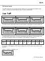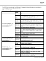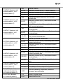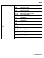
1
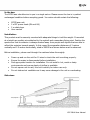
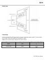
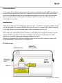
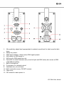
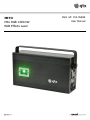
MITO Mito RGB 1420mW RGB Effects Laser Item ref: 152.766UK User Manual Thank you for choosing this QTX MITO high power laser. This high power effects laser offers a vast selection of patterns and grating effects including the popular "3D", "3D thread" and "galaxy" displays. The high precision pattern themes can be controlled via the 23 channel DMX-512 control. Intelligent time modulation mimics a two head laser system allowing two different patterns to be displayed simultaneously. The laser is best projected on to a flat surface, such as a wall or ceiling, or through smoke. An ideal addition to any lighting rig or for use in permanent installations such as nightclubs or discos, where it can produce a stunning laser display. Over 100 different patterns and 15 different grating effects RGB colour mixing can produce up to 7 colours Auto, sound-to-light, pattern select and 23 channel DMX operation modes Two head laser system modulation High power RGB laser heads totaling 1.42W (red 300mW, green 120mW, blue 1000mW) Key controlled for laser safety Warning: This item contains laser radiation, no user serviceable/repairable parts within. Please refer to licensed electrician to perform any required repair or maintenance. This product is strictly for professional use only. Approved personnel required to install and operate the unit, strictly following the laser health and safety guide HSG95. For detailed information regarding HSG95, please see the below web link: http://www.hse.gov.uk/pubns/books/hsg95.htm This product is a class 3B laser, which means extreme care needs to be taken when operating the device. This laser can cause permanent damage to eyesight through misuse or misconduct. Please read through this manual thoroughly before use. 152.766UK User Manual In the box: The MITO laser should arrive to you in a single carton. Please ensure the box is in perfect undamaged condition before accepting goods. You carton should contain the following: MITO laser unit 2 x IEC power leads (EU and UK) 2 x safety keys User manual Installation: This product must be securely mounted with adequate fixings to hold the weight. If mounted at a height use a safety wire attached to the eyebolt and a secondary fixing point. Position the aperture so that its emission is always directed away from people and objects that are able to reflect the emission towards people. In this regard the separation distances of 3 metres vertically and 2.5 metres horizontally, cited in HSG95 and shown below must be observed. Before installation, please read through the cautions below thoroughly: Power up and run the unit for 10 mins to check the unit is working properly. Ensure the mains is disconnected before installation. Find appropriate location for installation. Do not install in hot, moist or dusty environments and ensure plenty of airflow is available. Do not expose unit to rain, this unit is strictly for indoor use only. Do not obstruct air ventilation as it may cause damage to the unit or overheating. Side view: 152.766UK User Manual Aerial view: Connecting: Use the included UK or EU mains lead to connect to the mains power supply. To wire directly to the mains, earth wiring must be connected for safety. Please refer to below colour coding for the correct wiring. Wire colour Brown Blue Yellow/Green Connection Live Neutral Earth International Symbol L N 152.766UK User Manual Fuse replacement: In the event of fuse failure always ensure the mains is switched off and the IEC connection is removed before opening the fuse cover. Remove the fuse from the fuse holder and replace with a new one. Always used the correct fuse rating stated on the unit. Place the fuse cover back in the keyed slot, ensuring you are placing it back the correct way. Do not force the cover in the wrong way. Maintenance: There are no end-user serviceable parts within the unit. To maintain workable condition of the unit, we are advice to remove collected dust from the unit on a regular basis. Before cleaning or dusting, always ensure the mains power cable is removed from the unit. Use a soft cloth, lightly dampened with water or mild detergent to wipe off the dust from the casing. DO NOT use spray on the case as droplets may enter the unit through the front aperture or ventilation and cause damage to electronics inside. Remove the trapped dust from the ventilation holes of the unit with a vacuum cleaner with brush attachment, a dust blower or a hand brush. Product layout: 152.766UK User Manual 1. Mic sensitivity, adjust level appropriately to ambient sound level for ideal sound-to-light trace. 2. Safety key switch. 3. DMX signal indicator, flashes when DMX signal present. 4. XLR socket for DMX signal in. 5. XLR plug for DMX signal loop out. 6. Dip switch to switch between auto, sound to light and DMX mode, also serves as DMX initial address setting. 7. Built in microphone. 8. D connector for interlock control. 9. Ventilation fan, do not block. 10. Earth connection screw, DO NOT remove. 11. Fuse cover. 12. IEC socket for mains power in. 152.766UK User Manual DIP Switch Control: The MITO laser has 3 pre-programmed auto modes and 3 pre-programmed sound-to-light modes, to choose auto mode switches 9 and 10 must be switched off. Auto 1 Auto 2 Auto 3 To choose sound-to-light mode, switch 9 must be switch on and switch 10 must be switch off Sound-to-light 1 Sound-to-light 2 Sound-to-light 3 To switch to DMX mode, switch 10 must be switched on and switches 1-9 can be used to set the initial DMX address, below is the indication of DMX address for switches 1-9. DMX value DIP1 DIP2 DIP3 DIP4 DIP5 DIP6 DIP7 DIP8 DIP9 1 2 4 8 16 32 64 128 256 For example if DMX signal for MITO starts at channel 44, the DIP switch value need to be set as below: 4(DIP3) + 8(DIP4) + 32(DIP6) = 44 152.766UK User Manual The MITO can be controlled by DMX over 23 channels, below is the function indication for various DMX values in individual channels: *S2L – sound-to-light Channel DMX Function value CH1/CH12 (identical, ch1 controls pattern1, ch12 controls pattern 2) CH2/CH13 (identical, ch2 controls pattern1, ch13 controls pattern 2) CH3/CH14 (identical, ch3 controls pattern1, ch14 controls pattern 2) 0 Black out 1-6 Auto slide mode reduce pattern size to 50%@1 and 4, 25%@2 and 5, 12.5%@3 and 6 7-50 Auto slide mode full pattern size 51-56 Auto warp mode reduce pattern size to 50%@51 and 54, 25%@52 and 55, 12.5%@53 and 56 57-100 Auto warp mode full pattern size 101-106 S2L slide mode reduce pattern size to 50%@101 and 104, 25%@102 and 105, 12.5%@103 and 106 107-150 S2L slide mode full pattern size 151-156 S2L warp mode reduce pattern size to 50%@151 and 154, 25%@152 and 155, 12.5%@153 and 156 157-200 S2L warp mode full pattern size 201-230 Auto show mode 230-255 S2L show mode 0-200 Pattern selection 201-255 Auto/S2L (control by ch1) pattern warp/slide(control by ch1) 0-63 Manual zoom out, value increase to size down 64-96 Wobble effect clockwise 97-127 Wobble effect anti-clockwise 128-160 161-191 192-223 224-255 Auto/S2L (control by ch1) ½ size zoom in and out, value increase to speed up Auto/ S2L (control by ch1) zoom in, value increase to speed up Auto/ S2L (control by ch1) zoom out, value increase to speed up Auto/ S2L (control by ch1) full size zoom in and out, value increase to speed up. 152.766UK User Manual CH4/CH15 (identical, ch4 controls pattern1, ch15 controls pattern 2) 0-63 Manual rotation 64-191 Auto/S2L (control by ch1) 2 ways rotations 192-223 Auto/S2L (control by ch1) rotation clockwise 224-255 Auto/S2L (control by ch1) rotation anti-clockwise 0-63 CH5/CH16 (identical, ch5 controls pattern1, ch16 controls pattern 2) 64-127 128-255 0-63 CH6/CH17 (identical, ch6 controls pattern1, ch17 controls pattern 2) 64-127 128-255 0-63 CH7/CH18 (identical, ch7 controls pattern1, ch18 controls pattern 2) CH8/CH19 (identical, ch8 controls pattern1, ch19 controls pattern 2) 64-127 128-159 CH10/CH21 (identical, ch10 controls pattern1, ch21 controls pattern 2) CH11/CH22 (identical, ch11 controls pattern1, Manual flip around vertical axis Auto/S2L (control by ch1) contracting wave effect around vertical axis Auto/S2L (control by ch1) spiral effect around vertical axis 160-255 Auto/S2L (control by ch1) flip around vertical axis 0-63 Manual Flip around horizontal axis 64-127 128-159 160-255 CH9/CH20 (identical, ch9 controls pattern1, ch20 controls pattern 2) Manual warp/slide (control by ch1) around vertical axis Auto/S2L (control by ch1) wave effect around vertical axis Auto/S2L (control by ch1) warp/slide (control by ch1) around vertical axis Manual warp/slide (control by ch1) around horizontal axis Auto/S2L (control by ch1) wave effect around horizontal axis Auto/S2L (control by ch1) warp/slide (control by ch1) around horizontal axis Auto/S2L (control by ch1) contracting wave effect around horizontal axis Auto/S2L (control by ch1) spiral effect around horizontal axis Auto/S2L (control by ch1) flip around horizontal axis 0 Full pattern 1-127 Manual scroll pattern drawing step 0-100% 128-255 Auto/S2L (control by ch1) drawing effect 0-255 Definition(drawing) adjustment, definition increases with DMX value 0-15 Pattern original colour 16-31 Laser colour to red 152.766UK User Manual ch22 controls pattern 2) CH23 32-47 Laser colour to green 48-63 Laser colour to yellow 64-79 Laser colour to blue 80-95 Laser colour to purple 96-111 Laser colour to cyan 112-127 Laser colour to white (full power) 128-191 Uniform colour change 192-255 Graduate colour change by parts 0-31 Grating effect 1 32-47 Grating effect 2 48-63 Grating effect 3 64-79 Grating effect 4 80-95 Grating effect 5 96-111 Grating effect 6 112-127 Grating effect 7 128-143 Grating effect 8 144-159 Grating effect 9 160-175 Grating effect 10 176-191 Grating effect 11 192-207 Grating effect 12 208-223 Grating effect 13 224-239 Grating effect 14 240-255 Grating effect 15 152.766UK User Manual Trouble shooting: No power output Power on but no output DMX mode no output Check mains power is connected correctly and mains cable is in good condition. Check fuse is in working condition, if fuse continually blows stop use immediately and refer unit to qualified personnel. Check dip switch 10 is not switched on. Check key switch is switched on. Check interlock switch if there is one connected. If ambient temperature is low, laser head may take up to 30 min to warm up for max output. Ensure mic sensitivity is turned up if sound-to-light mode is selected. Check correct DMX lead is used (balanced XLR). Check DMX controller is not in blackout mode. Check if DMX controller has polarity switch and is correctly selected. Check laser DMX initial address number is set correctly on dip switch and switch 10 is switched on. Ensure DMX lead is not running along with high voltage cable. Ensure channel 1 and channel 12 value is not set at 0. Try alternative controller to ensure it is not faulty. This product complies with laser safety standard EN60825-1 2007. This product is classed as Electrical or Electronic equipment and should not be disposed with other household or commercial waste at the end of its useful life. The goods must be disposed of according to your local council guidelines. Errors and omissions excepted. Copyright© 2014. AVSL Group Ltd 152.766UK User Manual