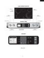
1
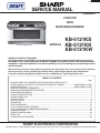
KB-5121KS/K/W
SERVICE MANUAL
S15R256KB5121
COOK TOP
WITH
MICROWAVE DRAWER
KB-5121KS pictured
MODELS
KB-5121KS
KB-5121KK
KB-5121KW
WARNING TO SERVICE PERSONNEL:
This service manual is intended for use by persons having electrical and mechanical training and a level of
knowledge of these subjects generally considered acceptable in the appliance repair trade. Sharp Electronics
Corporation cannot be responsible, nor assume any liability, for injury or damage of any kind arising from the
use of this manual.
Microwave ovens contain circuitry capable of producing very high voltage and current. Contact with the following
parts may result in a severe, possibly fatal, electrical shock. (High Voltage Capacitor, High Voltage Power
Transformer, High Voltage Rectifier and Heat sink etc., and Magnetron, High Voltage Harness etc..)
TABLE OF CONTENTS
Page
PRECAUTIONS TO BE OBSERVED BEFORE AND DURING SERVICING TO
AVOID POSSIBLE EXPOSURE TO EXCESSIVE MICROWAVE ENERGY ................... INSIDE FRONT COVER
BEFORE SERVICING ...................................................................................................... INSIDE FRONT COVER
WARNING TO SERVICE PERSONNEL ............................................................................................................... 1
MICROWAVE MEASUREMENT PROCEDURE .....................................................................................................3
FOREWORD AND WARNING ................................................................................................................................5
PRODUCT SPECIFICATIONS ............................................................................................................................... 6
POWER CONNECTION .........................................................................................................................................7
ANTI-TIP DEVICE ................................................................................................................................................. 8
CONTROL LAYOUT .............................................................................................................................................. 9
SCHEMATICS ..................................................................................................................................................... 10
TEST PROCEDURES .......................................................................................................................................... 13
TOUCH CONTROL PANEL ASSEMBLY ............................................................................................................. 24
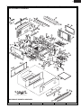
COOK TOP/MICROWAVE DRAWER DISASSEMBLY ........................................................................................ 32
WIRING DIAGRAMS ........................................................................................................................................... 39
PRINTED WIRING BOARDS ............................................................................................................................... 44
PARTS LIST ........................................................................................................................................................ 47
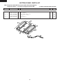
PACKING AND ACCESSORIES ......................................................................................................................... 55
SHARP ELECTRONICS CORPORATION
This document has been published to be used for after sales service only. The contents are subject to change without notice.
1
KB-5121KS/K/W
PRECAUTIONS TO BE OBSERVED BEFORE AND DURING SERVICING TO AVOID POSSIBLE EXPOSURE TO
EXCESSIVE MICROWAVE ENERGY
(a) Do not operate or allow the oven to be operated with the door open.
(b) Make the following safety checks on all ovens to be serviced before activating the magnetron or other microwave
source, and make repairs as necessary: (1) interlock operation, (2) proper door closing, (3) seal and sealing surfaces
(arcing, wear, and other damage), (4) damage to or loosening of hinges and latches, (5) evidence of dropping or
abuse.
(c) Before turning on microwave power for any service test or inspection within the microwave generating
compartments, check the magnetron, wave guide or transmission line, and cavity for proper alignment, integrity,
and connections.
(d) Any defective or misadjusted components in the interlock, monitor, door seal, and microwave generation and
transmission systems shall be repaired, replaced, or adjusted by procedures described in this manual before
the oven is released to the owner.
(e) A microwave leakage check to verify compliance with the Federal Performance Standard should be performed
on each oven prior to release to the owner.
BEFORE SERVICING
Before servicing an operative unit, perform a microwave emission check as per the Microwave Measurement Procedure outlined in this service manual.
If microwave emissions level is in excess of the specified limit, contact SHARP ELECTRONICS
CORPORATION immediately @1-800-237-4277.
If the unit operates with the door open, service person should 1) tell the user not to operate the oven and
2) contact SHARP ELECTRONICS CORPORATION and Food and Drug Administration's Center for
Devices and Radiological Health immediately.
Service personnel should inform SHARP ELECTRONICS CORPORATION of any certified unit found with
emissions in excess of 4mW/cm2. The owner of the unit should be instructed not to use the unit until the
oven has been brought into compliance.
2
KB-5121KS/K/W
WARNING TO SERVICE PERSONNEL
Range units contain circuitry capable of producing very high voltage and current, contact
with following parts may result in a severe, possibly fatal, electrical shock.
(Example)
High Voltage Capacitor, High Voltage Power Transformer, Magnetron, High Voltage
Rectifier Assembly, High Voltage Harness, Heating Elements, etc..
Read the Service Manual carefully and follow all instructions.
Before Servicing
When the testing is completed,
1. Disconnect the power source, and then remove covers.
2. Open the drawer and keep it open.
3. Discharge high voltage capacitor.
4. Reconnect the leads to the primary of the power
transformer.
5. Reinstall the covers.
6. Reconnect the power source.
7. Run the unit and check all functions.
1. Disconnect the power source, and then remove unit.
2. Open the drawer and keep it open.
3. Discharge high voltage capacitor.
WARNING: RISK OF ELECTRIC SHOCK.
DISCHARGE THE HIGH-VOLTAGE
CAPACITOR BEFORESERVICING.
After repairing
The high-voltage capacitor remains charged about 60
seconds after the oven has been switched off. Wait for 60
seconds and then short-circuit the connection of the highvoltage capacitor (that is the connecting lead of the highvoltage rectifier) against the chassis with the use of an
insulated screwdriver.
1. Reconnect all leads removed from components during
testing.
2. Reinstall the covers.
3. Reconnect the power supply cord.
4. Run the oven and check all functions.
Whenever troubleshooting is performed the power supply
must be disconnected. It may, in some cases, be necessary
to connect the power supply after the outer case has been
removed, in this event:
1. Disconnect the power source, and then remove neccessary
covers.
2. Open the drawer and keep it open.
3. Discharge high voltage capacitor.
4. Disconnect the leads to the primary of the power
transformer.
5. Ensure that the leads remain isolated from other
components and oven chassis by using insulation tape.
6. After that procedure, reconnect the power source.
1
Microwave ovens should not be operated empty. To test for
the presence of microwave energy within a cavity, place a
cup of cold water on the oven tray, close the drawer and set
the power to HIGH and set the microwave timer for two (2)
minutes. When the two minutes has elapsed (timer at zero)
carefully check that the water is now hot. If the water remains
cold carry out Before Servicing procedure and re-examine
the connections to the component being tested.
When all service work is completed and the oven is fully
assembled, the microwave power output should be checked
and a microwave leakage test should be carried out.
KB-5121KS/K/W
SAFE SERVICING PRACTICES
To avoid personal injury and/or property damage, it is important that Safe Servicing
Practices be observed. The following are some limited examples of safe practices:
1. DO NOT attempt a product repair if you have any doubts as to your ability to
complete it in a safe and satisfactory manner.
2. Before servicing or moving an appliance:
•
Disconnect the power source by tripping the circuit breaker to the
OFF position, then disconnecting the wiring.
3. Never interfere with the proper operation of any safety device.
4. USE ONLY REPLACEMENT PARTS CATALOGED FOR THIS APPLIANCE.
SUBSTITUTIONS MAY DEFEAT COMPLIANCE WITH SAFETY
STANDARDS SET FOR HOME APPLIANCES.
5. GROUNDING : The standard color coding for safety ground wires is GREEN , or
GREEN with YELLOW STRIPES . Ground leads are not to be used as current
carrying conductors. It is EXTREMELY important that the service technician
reestablish all safety grounds prior to completion of service. Failure to do so will
create a hazard.
6. Prior to returning the product to service, ensure that:
•
•
•
•
•
All electrical connections are correct and secure
All electrical leads are properly dressed and secured away from sharp edges,
high-temperature components, and moving parts
All non-insulated electrical terminals, connectors, heaters, etc. are adequately
spaced away from all metal parts and panels
All safety grounds (both internal and external) are correctly and securely
connected
All panels are properly and securely reassembled
ATTENTION!!!
This service manual is intended for use by persons having electrical and mechanical training
and a level of knowledge of these subjects generally considered acceptable in the appliance
repair trade. Sharp Electronics Corporation cannot be responsible, nor assume any liability,
for injury or damage of any kind arising from the use of this manual.
2
KB-5121KS/K/W
MICROWAVE MEASUREMENT PROCEDURE
A. Requirements:
1) Microwave leakage limit (Power density limit): The power density of microwave radiation emitted by a microwave oven
should not exceed 1mW/cm2 at any point 5cm or more from the external surface of the oven, measured prior to acquisition
by a purchaser, and thereafter (through the useful life of the oven), 5 mW/cm2 at any point 5cm or more from the external
surface of the oven.
2) Safety interlock switches:
Primary interlock relay switch shall prevent microwave radiation emission in excess of the requirement as above
mentioned. Secondary interlock relay and door sensing switch shall prevent microwave radiation emission in excess of
5 mW/cm2 at any point 5cm or more from the external surface of the oven.
B. Preparation for testing:
Before beginning the actual measurement of leakage, proceed as follows:
1) Make sure that the actual instrument is operating normally as specified in its instruction booklet.
Important:
Survey instruments that comply with the requirement for instrumentation as prescribed by the performance standard for
microwave ovens, 21 CFR 1030.10(c)(3)(i), must be used for testing.
2) Place the load of 275±15 ml (9.8 oz) of tap water initially at 20±5O C (68OF) in the center of the oven cavity.
The water container shall be a low form of 600 ml (20 oz) beaker with an inside diameter of approx. 8.5 cm (3-1/2 in.) and
made of an electrically nonconductive material such as glass or plastic.
The placing of this standard load in the oven is important not only to protect the oven, but also to insure that any leakage
is measured accurately.
3) Set the cooking control on Full Power Cooking Mode.
4) Close the drawer and select a cook cycle of several minutes. If the water begins to boil before the survey is completed,
replace it with 275 ml of cool water.
C. Leakage test:
Closed-drawer leakage test (microwave measurement):
1) Grasp the probe of the survey instrument and hold it perpendicular to the gap between the drawer and the body of the
oven.
2) Move the probe slowly, not faster than 1 in./sec. (2.5 cm/sec.) along the gap, watching for the maximum indication on the
meter.
3) Check for leakage at the drawer screen, sheet metal seams and other accessible positions where the continuity of the
metal has been breached (eg., around the switches, indicator, and vents).
While testing for leakage around the drawer, pull the drawer away from the front of the oven as far as is permitted by the
closed latch assembly.
4) Measure carefully at the point of highest leakage and make sure that the highest leakage is no greater than 4mW/cm2,
and that the primary interlock switch/secondary interlock relay does turn the oven OFF before any door movement.
NOTE: After servicing, record data on service invoice and microwave leakage report.
3
KB-5121KS/K/W
NOTES
4
KB-5121KS/K/W
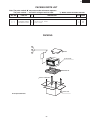
SERVICE MANUAL
COOK TOP
PRODUCT DESCRIPTION
WITH
MICROWAVE DRAWER
POWER CONNECTION
ANTI-TIP DEVICE
KB-5121KS / KB-5121KK / KB-5121KW
FOREWORD
This Manual has been prepared to provide Sharp Electronics Corp.
Service Personnel with Operation and Service Information for the
SHARP COOK TOP WITH MICROWAVE DRAWER, KB-5121KS/JK/
JW.
SCHEMATICS
TEST PROCEDURE
It is recommended that service personnel carefully study the entire text
of this manual so that they will be qualified to render satisfactory
customer service.
TOUCH CONTROL PANEL
Check the interlock switches and the door seal carefully. Special
attention should be given to avoid electrical shock and microwave
radiation hazard.
COMPONENT REPLACEMENT
AND ADJUSTMENT PROCEDURE
WARNING
Never operate the oven until the following points are ensured.
(A) The door is tightly closed.
(B) The door brackets and hinges are not defective.
(C) The door packing is not damaged.
(D) The door is not deformed or warped.
(E) There is not any other visible damage with the oven.
WIRING DIAGRAM
Servicing and repair work must be carried out only by trained service
personnel.
PARTS LIST
DANGER
Certain initial parts are intentionally not grounded and present
a risk of electrical shock only during servicing. Service
personnel - Do not contact the following parts while the
appliance is energized;
High Voltage Capacitor, Power Transformer, Magnetron, High
Voltage Rectifier Assembly, High Voltage Harness;
If provided, Vent Hood, Fan assembly, Cooling Fan Motor.
All the parts marked “*” on parts list are used at voltages more than
250V.
Removal of the outer wrap gives access to voltage above 250V.
All the parts marked “ Δ” on parts list may cause undue microwave
exposure, by themselves, or when they are damaged, loosened or
removed.
SHARP ELECTRONICS CORPORATION
SHARP PLAZA, MAHWAH,
NEW JERSEY 07430-2135
5
KB-5121KS/K/W
COOK TOP SPECIFICATION
ITEM
DESCRIPTION
Power Requirements
120 /208 - 120/240Volts / 46/50 Amperes
60 Hertz
Single phase, 3 wire grounded
Cook Top Heating Elements
Two 6" - 1200W
One 8" - 2000W
One 6"/9" - 1200/2400W
Control Complement
One 6" - 100W
Touch Navigation System
Clock ( 1:00 - 12:59 )
Timer (0 - 99 min. 99 seconds)
Kitchen Timer, Cooktop Warm, Stop/Clear,
MICROWAVE DRAWER SPECIFICATION
ITEM
DESCRIPTION
Power Output
1000 watts (IEC TEST PROCEDURE)
Operating frequency of 2450MHz
Cooking Cavity Dimensions
Width 17-11/32
Height 5-7/8"
Depth 17-1/8"
1.0 Cubic Feet
Control Complement
Touch Navigation System
Clock ( 1:00 - 12:59 )
Timer (0 - 99 min. 99 seconds)
Microwave Power for Variable Cooking
Repetition Rate;
P-HI ................................................. Full power throughout the cooking time
P-90 .................................................................... approx. 90% of Full Power
P-80 .................................................................... approx. 80% of Full Power
P-70 .................................................................... approx. 70% of Full Power
P-60 .................................................................... approx. 60% of Full Power
P-50 .................................................................... approx. 50% of Full Power
P-40 .................................................................... approx. 40% of Full Power
P-30 .................................................................... approx. 30% of Full Power
P-20 .................................................................... approx. 20% of Full Power
P-10 .................................................................... approx. 10% of Full Power
P-0 ..................................................... No power throughout the cooking time
Kitchen Timer, Cooktop Warm, Stop/Clear, Start, Start, Minute Plus, OPEN, CLOSE.
Oven Cavity Light
Yes
Safety Standard
UL Listed
FCC Authorized
DHHS Rules, CFR, Title 21, Chapter 1, Subchapter J
6
KB-5121KS/K/W
POWER CONNECTION
4-WIRE CONNECTION
SELECTING 208 OR 240 VOLT CONNECTION
This appliance can be set for 208V or 240V. The voltage setting for
your appliance is pre-set at 240V from the factory. Follow these
steps to change the voltage setting.
When installing to a 4-wire electrical system, new construction,
mobile home and recreational vehicle or when local codes do not
permit grounding through neutral.
1 Locate the voltage switch on the left side of the appliance
(facing the front). See Figure 1.
1 Disconnect the power supply.
2 In the junction box connect the appliance and residence cable
wires as shown in Figure 4.
2 Remove the screw and rotate the switch plate 180˚ as indicated
in the Figure 2.
3 Reinsert the switch plate and replace screw as indicated
in Figure 3. The voltage setting is indicated by the visible
marking.
Red wires
Green wires
Conduit connector
(not supplied)
Appliance
conduit & wires
Power supply
White wires (nutral)
Black wires
Figure 4
Figure 1
3-WIRE CONNECTION
When local codes permit connecting the cabinet-grounding conductor to the neutral (white) wire.
Screw
2 In the junction box connect the appliance and residence cable
wires as shown in Figure 5.
208V
240V
1 Disconnect the power supply.
Screw
180˚
Black wires
Red wires
Figure 2
Figure 3
Conduit connector
(not supplied)
Note: This appliance must be properly grounded
Appliance
conduit & wires
Attention Installer: This appliance must be hard wired (direct
wired) into an approved junction box. A plug and receptacle is
NOT permitted on this product.
Green wire
(ground)
Power supply
White wires (nutral)
Figure 5
REINSTALL JUNCTION BOX COVER
Do not shorten the flexible conduit. The conduit strain relief clamp
(supplied by installer) must be securely attached to the junction box
and the flexible conduit must be securely attached to the clamp. If
the flexible conduit will not fit with the junction box, do not install
the appliance until a clamp of proper size has been obtained.
7
KB-5121KS/K/W
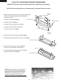
ADJUST ANTI-TIP BRACKET
Measure the thickness of the counter. See Figure 6. Locate the
Anti-Tip Bracket on the backside of the appliance. See Figure 7.
Loosen screws and adjust space between the glass cooktop and
bracket to match the counter thickness plus 1/16”. See Figure 8.
Tighten the screws to secure the bracket at the correct counter height
dimension.
Measure
thickness
Figure 6
Anti-Tip bracket
Lossen screws to adjust
Back of unit
Figure 7
countertop
thickness +1/16"
from bottom of
cooktop glass bracket
to top of Anti-Tip bracket
Figure 8
8
KB-5121KS/K/W
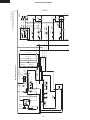
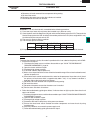
KB-5121KS
9
Schematic-Off Condition
KB-5121KS/K/W
L1
BLK
YLW
INSIDE
OUTSIDE
RIGHT FRONT
SURFACE
ELEMENT
P1B /
4
RED
YLW
P1A/
4A
1a
2
L2
RED
RED
RED
P1
RED
WHT
L2
L1
YLW
RED
E2
B3
E1
DM
C7
MICROWAVE DRAWER
DOOR OPEN-CLOSE
MOTOR
RY8
INDICATOR LIGHT
2a
BRN
PROTECTOR
RED
L2/
P1
NOISE FILTER BOARD
CONTROL
S1
S2
4a
H2/
2
WHT
RED
RED *3
WHT
YLW
4
WHT
RED
P2
YLW*2
P
BLK
YLW
L1/
P2
2a
RED
WHT
ORG
CONTROL UNIT
E3
DM
DOOR
POSITION
SWITCH
REAR
COOLING FAN
DC MOTOR
DOOR
POSITION
SWITCH
FRONT
RED
BRN
A6
A1
A2
LOW VOLTAGE
TRANSFORMER
A4
B1
WHT
10
YLW
502
3
502
1
MG
THERMAL
CUT-OUT
VOLTAGE SWITCH
CAPACITOR
1.00 " F
AC 2300V
2
SWITCHING POWER SUPPLY UNIT
502
2
ORG
MONITOR SWITCH
P1/
4
501
3
501
1
GRN
OVEN
THERMAL
CUT-OUT
POWER TRANSFORMER
GRY
COM
BRN
PROTECTOR
BLK
YLW
WHT
RED
RED
RED
N.O.
RED
BLK
2a
RED
L2/
P1
RED
RED
L
BLU
BLK
M5
BLK
N5
1a
PROTECTOR
H2/
2
INDICATOR LIGHT
WHT
2a
RED
RED
1a
2
1a
RED
RED
RED
L2
NOISE SUPRESSION COIL
RIGHT REAR
SURFACE
ELEMENT
P1/
4
2
L2/
P1
RY6
WARMER
SURFACE
ELEMENT
YLW
P1/
4
PROTECTOR
H2/
2
LINE CROSS CAPACITOR 1.0 " F 250V
WHT
YLW
BLK
BLK
YLW LEFT FRONT
SURFACE
ELEMENT
BRN
CONTROL UNIT
N1 RED
RY7
ORG
WHT
YLW
H1/
4
P
YLW
H1/
4
BLK
P
LEFT REAR
SURFACE
RED
FUSE
20A
CONTROL
L1/
P2
CONTROL
L1/
P2
YLW*2
2a
YLW
C3
WHT
PROTECTOR
RESISTOR 470 kW 1/2W
BLK
M4
RED
BRN
BRN
BLK
1a
C5
MAGNETRON
HV RECTIFIER
HOT SURFACE LIGHT
RR
RF
LF
RY2
N4
RY3
STIRRER MOTOR
COM
F1
N2 ORG
FAN MOTOR
P1/ ELEMENT
2
4
WHT
YLW
BLU
BRN
LR
F2
H1/
4
WHT
YLW
BRN
YLW
BLU
BLK
YLW
BRN
BRN
M1
SECONDARY INTELOCK SWITCH
BLK
F3
BLK
ORG
BLK
BLK
1b
1b
YLW
BLK
L
WHT
MICROWAVE DRAWER
RED
BRN
CONTROL
2b
2b
BLK
BLU
BLK
BLU
1b
1b
2b
2b
L1
BLK
DOOR
SENSING
SWITCH
M6
ORG
LINE BYPASS CAPACITOR
0.0033 " F 250V
LINE BYPASS CAPACITOR
0.0033 " F 250V
PRIMARY INTERLOCK
RELAY
RED
ORG
OL
M7
OVEN LAMP
WHT
WHT
BLK
BLU
YLW
YLW
YLW
RED
GRN M3
HUMIDITY
SENSOR
N3
ORG
SM
WHT
WHT
BLK
FM
WHT
WHT
BLU
HOT SURFACE
LIGHT
SWITCHES
YLW
BLK
BLK *3
YLW
1. Circuits / wire colors are subject to change without notice.
2. Terminal that is located on the right side on lamp sockets back view
must be connected to neutral wire.
NOTES:
WHT *3
N
COOK TOP
BLK
BLK
KB-5121KS/K/W
RED
RED
RED
L2
RED *3
RED
L2
L1
BLK *3
BLK
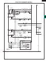
COOK TOP SCHEMATIC (DETAIL)
CONTROL
S1
S2
RED
RED
INDICATOR LIGHT
YLW
YLW
P1B /
4
RED
YLW
P1A/
4A
4
RED
4a
P2
BLK
YLW
BLK
INSIDE
OUTSIDE
2
P1
2a
RED
PROTECTOR
RED
WHT
RIGHT FRONT
SURFACE
ELEMENT
WHT
L1/
P2
BRN
1a
P
ORG
YLW*2
P1/
4
H1/
4
WHT
Y LW
YLW
RIGHT REAR
SURFACE
ELEMENT
1a
H2/
2
L2/
P1
2a
RED
PROTECTOR
YLW
WHT
CONTROL
Y LW
2
BLK
BLK
P1/
4
YLW
2
1a
WARMER
SURFACE
ELEMENT
L1/
P2
BLK
ORG
P
2a
PROTECTOR
INDICATOR LIGHT
YLW
RED
YLW
L1/
P2
H1/
4
BLK
CONTROL
2
WHT
L2/
P1
RED
RED
2a
1a
LEFT FRONT
SURFACE
ELEMENT
H2/
2
PROTECTOR
L2
P
YLW*2
BLK
BLK
BLK
YLW
H1/
4
WHT
LEFT REAR
SURFACE
YLW
CONTROL
P1/
4
P1/ ELEMENT
2
4
WHT
YLW
BRN
H2/
2
RED
2a
1a
L2/
P1
2b
BLK
BLU
2b
BLK
BLU
2b
BLU
HOT SURFACE LIGHT
1b
RR
YLW
BRN
BRN
YLW
BLU
BLU
YLW
BLK
BLK
YLW
YLW
YLW
RF
1b
1b
1b
LR
WHT
2b
BLK
BLU
WHT
YLW
PROTECTOR
LF
HOT SURFACE
LIGHT
SWITCHES
N
WHT *3
11
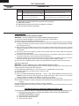
KB-5121KS/K/W
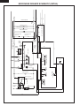
MICROWAVE DRAWER SCHEMATIC (DETAIL)
RED
WHT
RED
RED
L1
BLK
NOISE FILTER BOARD
L
L
501
3
501
1
FUSE
20A
SWITCHING POWER SUPPLY UNIT
RESISTOR 470 kW 1/2W
LINE CROSS CAPACITOR 1.0 " F 250V
NOISE SUPRESSION COIL
RED
GRN
LINE BYPASS CAPACITOR
0.0033 " F 250V
LINE BYPASS CAPACITOR
0.0033 " F 250V
502
2
RED
502
3
502
1
OVEN
THERMAL
CUT-OUT
ORG
BLK
RED
WHT
GRN M3
COM
RY7
N2 ORG
RY6
ORG
N3
YLW
C3
SM
RY3
STIRRER MOTOR
RED
ORG
PRIMARY INTERLOCK
RELAY
GRY
BRN
A6
A1
A2
CAPACITOR
1.00 " F
AC 2300V
HV RECTIFIER
MAGNETRON
B1
WHT
WHT
12
LOW VOLTAGE
TRANSFORMER
A4
VOLTAGE SWITCH
BRN
BLK
CONTROL UNIT
RED
BLK
E3
BLK
POWER TRANSFORMER
BLK
DM
M5
COOLING FAN
DC MOTOR
M4
RED
DOOR
POSITION
SWITCH
REAR
MONITOR SWITCH
BRN
DOOR
POSITION
SWITCH
FRONT
RED
BRN
COM
M6
M7
BRN
RY8
C7
N.O.
RED
OL ORG
OVEN LAMP
N4
N5 BLK
RY2
WHT
WHT
DM
FAN MOTOR
BLU
WHT
WHT
MICROWAVE DRAWER
DOOR OPEN-CLOSE
MOTOR
FM
N1 RED
BLK
C5
WHT
WHT
E2
E1
B3
F1
RED
F2
RED
ORG
CONTROL UNIT
F3
Y LW
HUMIDITY
SENSOR
WHT
MG
THERMAL
CUT-OUT
M1
BRN
BRN
SECONDARY INTELOCK SWITCH
DOOR
SENSING
SWITCH
KB-5121KS/K/W
TEST PROCEDURES
PROCEDURE
LETTER
A
COMPONENT TEST
TOUCH CONTROL PANEL ASSEMBLY TEST
The touch control panel consists of circuits including semiconductors such as LSI, ICs, etc. Therefore,
unlike conventional microwave ovens, proper maintenance cannot be performed with only a voltmeter
and ohmmeter.
In this service manual, the touch control panel assembly is divided into three units, Control Unit and
Keyboard Unit and Power Unit, and troubleshooting by unit replacement is described according to the
symptoms indicated.
Before testing,
1) Disconnect the power source, and then disassemble as per "COOK TOP/MICROWAVE DRAWER
DISASSEMBLY" page 32.
2) Open the drawer and block it open.
3) Discharge high voltage capacitor.
4) Disconnect the leads to the primary of the power transformer.
5) Ensure that these leads remain isolated from other components and oven chassis by using
insulation tape.
1. Keyboard Unit.
NOTE ;
1) Check Keyboard unit connection before replacement.
2) Reconnect all leads removed from components during testing.
3) Re-install the outer case (cabinet).
4) Reconnect the power source after the outer case is installed.
5) Run the oven and check all functions.
The following symptoms indicate a defective keyboard unit.
a) When touching the pads, a certain pad produces no signal at all.
b) When touching a number pad, two figures or more are displayed.
c) When touching the pads, sometimes a pad produces no signal.
If the Keyboard unit is defective.
1) Disconnect the power source, and then remove outer case.
2) Open the door and block it open.
3) Discharge high voltage capacitor.
4) Replace the Keyboard unit.
5) Reconnect all leads removed from components during testing.
6) Re-install the covers.
7) Reconnect the power supply cord after the outer case is installed.
8) Run the oven and check all functions.
2. Control Unit
The following symptoms indicate a defective control unit. Before replacing the control unit, perform
the Keyboard unit test (Procedure J) to determine if control unit is faulty.
2-1 In connection with indicators
a) At a certain digit, all or some segments do not light up.
b) At a certain digit, brightness is low.
c) Only one indicator does not light.
d) The corresponding segments of all digits do not light up; or they continue to light up.
e) Wrong figure appears.
f) A certain group of indicators do not light up.
g) The figure of all digits flicker.
2-2 Other possible problems caused by defective control unit.
a) Buzzer does not sound or continues to sound.
b) Clock does not operate properly.
c) Cooking is not possible.
3. Power Unit or Touch Control Transformer
a) Fan motor, stirrer motor, oven lamp or electrical parts do not turn on or do not turn off.
b) Digital display on the control unit does not show anything.
When testing is completed,
1) Disconnect the power source, and then disassemble as per "COOK TOP/MICROWAVE DRAWER
DISASSEMBLY" page 32.
2) Open the drawer and block it open.
3) Discharge high voltage capacitor.
13
KB-5121KS/K/W
TEST PROCEDURES
PROCEDURE
LETTER
COMPONENT TEST
4)
5)
6)
7)
B
Reconnect all leads removed from components during testing.
Re-install the covers.
Reconnect the power source after the outer case is installed.
Run the oven and check all functions.
KEYBOARD UNIT TEST
1. Disconnect the power source, and then disassemble as per "COOK TOP/MICROWAVE DRAWER
DISASSEMBLY" page 32.
2. Open the drawer and block it open.
3. Discharge high voltage capacitor.
4. If the display fails to clear when the STOP/CLEAR pad is depressed, first verify the wire harness and
connectors are making good contact between the control unit and the keyboard, verify that the door
sensing switch operates properly; that is the contacts are closed when the door is closed and open
when the door is open.
5. Remove the old keyboard unit and install the new keyboed unit (as the normal keyboard unit).
6. Reconnect the wire harness to the keyboard unit.
7. If the control unit responds by clearing with a beep when the stop/clear pad is touched, the old keyboard
unit is faulty and must be replaced. If the control unit does not respond, it is faulty and must be replaced.
If a specific pad does not respond, the above method may be used (after clearing the control unit) to
determine if the control unit or keyboed unit is at fault.
8. Reconnect all leads removed from components during testing.
9. Re-install the covers.
10.Reconnect the power source after the outer case is installed.
11.Run the oven and check all functions.
C
RELAY TEST
1. Disconnect the power source, and then disassemble as per "COOK TOP/MICROWAVE DRAWER
DISASSEMBLY" page 32.
2. Open the drawer and block it open.
3. Discharge high voltage capacitor.
4. Disconnect the leads to the primary of the power transformer.
5. Ensure that these leads remain isolated from other components and oven chassis by using insulation tape.
6. After that procedure, re-connect the power supply cord.
7. Remove the covers and check voltage between Pin Nos. 1 and 3 of the 2 pin connector (CN-B) on the
power unit with an A.C. voltmeter.
The meter should indicate 116 or 120 volts, if not check oven circuit.
RY1 and RY2 Relay Test
These relays are operated by D.C. voltage
Check voltage at the relay coil with a D.C. voltmeter during the microwave cooking operation.
DC. voltage indicated .................... Defective relay.
DC. voltage not indicated ............... Check diode which is connected to the relay coil. If diode is good,
control unit is defective.
RELAY SYMBOL
RY1
RY2
RY3
RY4
RY5
RY6
RY7
RY8
RY9
RY10
RY11
RY-B
RY-C
OPERATIONAL VOLTAGE
Approx.
Approx.
Approx.
Approx.
Approx.
Approx.
Approx.
Approx.
Approx.
Approx.
Approx.
Approx.
Approx.
18V
18V
18V
18V
24V
24V
24V
24V
24V
24V
24V
24V
24V
D.C.
D.C.
D.C.
D.C.
D.C.
D.C.
D.C.
D.C.
D.C.
D.C.
D.C.
D.C.
D.C.
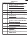
14
CONNECTED COMPONENTS
Oven lamp / Stirrer motor
Power transformer
Oven common relay
Top heater
Fan motor (Microwave)
Fan motor (Oven)
Oven lamp (Oven)
Door lock motor (Oven)
Convection motor
Warmer (Cook top)
Switching power supply
Bottom heater
Convection heater
KB-5121KS/K/W
TEST PROCEDURES
PROCEDURE
LETTER
COMPONENT TEST
8. Reconnect all leads removed from components during testing.
9. Re-install the covers.
10. Reconnect the power source after the cabinets are installed.
11. Run the drawer and check all function.
D
DEFROST TEST
WARNING : The unit should be fully assembled before following procedure.
(1) Place one cup of water in the center of the turntable tray in the oven cavity.
(2) Close the door, touch the Stop/Clear (M) pad and touch the Defrost pad on the LCD. Then touch the
Steaks/Chops pad on the LCD. And touch the number pad 5 on the LCD. (Now, weight 0.5lb is set.)
And then touch the start pad on the LCD.
(3) The oven is in Defrost cooking condition.
(4) The oven will operate as follows
WEIGHT
0.5lb
1ST STAGE
LEVEL
TIME
60%
20sec.
2ND STAGE
LEVEL
TIME
40%
20sec.
3RD. STAGE
LEVEL TIME
30%
45sec.
(5) If improper operation is indicated, the control unit is probably defective and should be checked.
E
PROCEDURES TO BE TAKEN WHEN THE FUSE ON THE PRINTED WIRING BOARD (PWB) IS
OPEN.
To protect the electronic circuits, this model is provided with a fuse added to the primary on the PWB.
1. Fuse check and repairs.
1) Disconnect the power source, and then disassemble as per "COOK TOP/MICROWAVE
DRAWER DISASSEMBLY" page 32.
2) Open the drawer and block it open.
3) Discharge high voltage capacitor.
4) If the Fuse is blown, replace power unit.
5) Make a visual inspection of the varistor. Check for burned damage. If the varistor has been burned,
replace the power unit.
6) Examine the touch control transformer with a tester for the presence of layer short-circuit (check
the primary coil resistance which is approximately 60Ω ± 10%). If any abnormal condition is
detected, replace the touch control transformer.
7) Reconnect all leads removed from components during testing.
8) Re-install the covers.
9) Reconnect the power source after the outer case is installed.
10) Run the oven and check all functions.
2. Follow the troubleshooting guide given below, if indicator does not light up after above check and
repairs are finished.
1) Disconnect the power source, and then disassemble as per "COOK TOP/MICROWAVE DRAWER
DISASSEMBLY" page 32.
2) Open the door and block it open.
3) Discharge high voltage capacitor.
4) Disconnect the leads to the primary of the power transformer.
5) Ensure that these leads remain isolated from other components and oven chassis by using
insulation tape.
6) After that procedure, re-connect the power supply cord.
7) Follow the troubleshooting guide given below for repair.
15
KB-5121KS/K/W
TEST PROCEDURES
PROCEDURE
LETTER
COMPONENT TEST
STEPS
8)
9)
10)
11)
CAUSE OR CORRECTION
1
The rated AC voltage is not present between Check supply voltage and oven power cord.
Pin Nos. 1and 3 of the 2-pin connecter (CN-B).
2
The rated AC voltage is present at primary
side of touch control transformer.
Touch control transformer or secondary circuit defective.
Check and replace touch control transformer or power
unit .
Reconnect all leads removed from components during testing.
Re-install the covers.
Reconnect the power source after the cabinets are installed.
Run the oven and check all functions.
AH SENSOR TEST
Checking the initial sensor cooking condition
WARNING : The oven should be fully assembled before following procedure.
(1) The oven should be plugged in at least two minutes before sensor cooking.
(2) Room temperature should not exceed 95oF (35oC).
(3) The unit should not be installed in any area where heat and steam are generated. The unit should not be
installed, for example, next to a conventional surface unit. Refer to the “INSTALLATION INSTRUCTIONS”
of the operation manual.
(4) Exhaust vents are provided on the back of the unit for proper cooling and air flow in the cavity. To permit
adequate ventilation, be sure to install so as not to block these vents. There should be some space for
air circulation.
(5) Be sure the exterior of the cooking container and the interior of the oven are dry. Wipe off any moisture
with a dry cloth or paper towel.
(6) The Sensor works with food at normal storage temperature. For example, chicken pieces would be at
refrigerator temperature and canned soup at room temperature.
(7) Avoid using aerosol sprays or cleaning solvents near the oven while using Sensor settings. The sensor
will detect the vapor given of by the spray and turn off before food is properly cooked.
(8) If the sensor has not detected the vapor of the food, ERROR will appear and the oven will shut off.
Water load cooking test
WARNING : The oven should be fully assembled before following procedure.
<
Make sure the oven has been plugged in at least two minutes before checking sensor cook operation. The
cabinet should be installed and screws tightened.
(1) Fill approximately 200 milliliters (7.2 oz) of tap water in a 1000 milliliter measuring cup.
(2) Place the container on the center of tray in the oven cavity.
(3) Close the door.
(4) Touch the UPER MICROWAVE OVEN pad,
pad,
pad, START MINUTE PLUS pad and the
SENSOR LOAD pad on the LCD. And touch the number pad 4 once. Now, the oven is in the sensor
cooking condition, and "20BIT" and "MICRO" will appear in the display.
(5) The oven will operate for the first 16 seconds, without generating microwave energy.
NOTE: ERROR will appear if the door is opened or STOP/CLEAR pad is touched during first stage of sensor
cooking.
(6) After approximately 16 seconds, microwave energy is produced.
If ERROR is displayed or the oven does not turn off, replace the AH sensor or check the control unit, refer to
explanation below.
<
F
OCCURRENCE
TESTING METHOD FOR AH SENSOR AND/OR CONTROL UNIT
To determine if the sensor is defective, the simplest method is to replace it with a new replacement sensor.
1) Disconnect the power source, and then disassemble as per "COOK TOP/MICROWAVE
DRAWER DISASSEMBLY" page 32.
2) Open the drawer and block it open.
3)
4)
Discharge high voltage capacitor.
Remove the AH sensor.
16
KB-5121KS/K/W
TEST PROCEDURES
PROCEDURE
LETTER
COMPONENT TEST
<
Install the new AH sensor.
Reconnect all leads removed from components during testing.
Re-install the outer case (cabinet).
Reconnect the power source after the cabinets are installed.
Reconnect the oven to the power supply and check the sensor cook operation as follows:
9-1. Fill approximately 200 milliliters (7.2 oz) of tap water in a 1000 milliliter measuring cup.
9-2. Place the container on the center of tray in the oven cavity.
9-3. Close the door.
9-4. Touch the UPER MICROWAVE OVEN pad, pad, pad, START MINUTE PLUS pad and the
SENSOR LOAD pad on the LCD. And touch the number pad 4 once.
9-5. The control panel is in automatic Sensor operation.
9-6. The oven turns off automatically, and the time for detecting moisture will be displayed.
If new sensor dose not operate properly, the problem is with the control unit, and refer to explanation below.
<
(5)
(6)
(7)
(8)
(9)
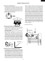
CHECKING CONTROL UNIT
(1) Disconnect the power source, and then disassemble as per "COOK TOP/MICROWAVE
DRAWER DISASSEMBLY" page 32.
(2) Open the drawer and block it open.
<
Discharge high voltage capacitor.
Disconnect the sensor connector that is mounted to control panel.
Then connect the dummy resistor circuit (see fig.) to the sensor connector of control panel.
Disconnect the leads to the primary of the power transformer.
Ensure that these leads remain isolated from other components and oven chassis by using insulation tape.
After that procedure, re-connect the power supply cord.
Check the sensor cook operation proceed as follows:
9-1. Close the door.
9-2. Touch the UPER MICROWAVE OVEN pad,
pad, pad, START MINUTE PLUS pad and the
SENSOR LOAD pad on the LCD. And touch the number pad 4 once.
9-3. The control panel is in the sensor cooking operation.
9-4. After approximately 25 seconds, push plunger of select switch for more than 3 seconds. This
condition is same as judgement by AH sensor.
9-5. After approximately 3 seconds, the display shows “ X X . X X “ which is the time for detecting moisture.
If the above is not the case, the control unit is probably defective.
If the above is proper, the AH sensor is probably defective.
(10) Disconnect the power source, and the covers.
(11) Open the door and block it open.
(12) Discharge high voltage capacitor.
(13) Disconnect the dummy resistor circuit from the sensor connector of control panel.
(14) Carry out necessary repair.
(15) Reconnect all leads removed from components during testing and repairing.
(16) Re-install the covers.
(17) Reconnect the power source after the cabinets are installed. Run the oven and check all functions.
(18) Carry out "Water load cooking test" again and ensure that the oven works properly.
<
(3)
(4)
(5)
(6)
(7)
(8)
(9)
R1, R2 : 22Ω ± 1% 1/2W
R3 : 4.3kΩ ± 5% 1/4W
R4 : 1MΩ ± 5% 1/4W
Plunger
NC
NO
F-1
F-2
To connector (F)
on Control Unit.
1
2
3
COM
COM NO
R1
F-3
CONNECTOR
R2
R3
R4
Sensor Dummy Resistor Circuit
17
NC
KB-5121KS/K/W
TEST PROCEDURES
PROCEDURE
LETTER
G
COMPONENT TEST
SURFACE
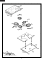
ELEMENTCONTROL SYSTEMS
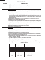
Di al Posit ion
Contacts
Two types of surface elements control systems are
covered in this manual.
1.
Standard infinite switch.
2.
Dual infinite switch.
OFF
LO-MED
HI
L1 - P
O
X
X
L1 - H 1
O
X
X
L2 - H 2
O
X- C
X
O
X
- open
- closed
P1
Standard infinite switch:
The surface elements and standard infinite switches provide an infinite choice of heat settings for cooking. Controls are safety type and must be pushed in before turning. All surface controls are marked on the control panel
for their respective heating element. Power is supplied
to the surface elements through the infinite switch contacts L1-H1 and L2-H2. During actual surface element
operation, if the control is set to the high position contacts L2-H2 are lock closed providing continuous power
to the element. In all other setting contacts L2-H2 will
cycle to maintain the correct heat setting. Contacts L1P provide power to the surface element indicator light.
4
2
PILOT
P2
Element does not heat:
Checking the system with a Voltmeter, if the element
does not heat up.
Troubleshooting:
1.
Remove the back of the control panel to
expose the switch terminals.
There are four ways a surface control system with a
standard infinite switch can fail.
2.
With a Voltmeter set for AC on a scale higher
than 240 Volts measure the voltage drop
between terminals L1 and L2. If the meter
reads zero the wiring between the main
terminal block on the range and the switch is
open. If the meter reads line to line voltage
(around 240 VAC) go to step 3.
3.
With the switch turned to the high position
measure the voltage drop between terminals
H1 and H2. If the meter reads zero the switch
is defective. If the meter reads line to line
voltage the switch is good. If the range has
standard elements go to step 4. If the range
has a glass smooth go to step 5.
4.
Remove the element and measure the
voltage drop between terminals of the terminal
block. If the meter reads zero the terminal
block or the wiring between the switch and the
terminal block is open. If the meter reads line
to line voltage the element is defective.
1.
The element does not heat.
2.
The switch does not cycle the element off and
on when set to a position other than high.
3.
The element operates correctly, but the
indicator light does not glow.
4.
Indicator light glows with all infinite switches
in the off position.
NOTE: If the indicator light glows very dimly
with all the switches in the off position. This
problem is caused by a capacitive feed over in
the wiring and can be corrected by connecting
a 100,000 Ohm 1/4 watt resistor in parallel with
the light.
Continuity tests can be performed on the infinite switch
contacts. All tests should be performed with power to
the range disconnected, and wiring removed from the
switch. Set an ohmmeter on R X 1K scale and check
the contacts in the following chart and switch terminal
diagram.
NOTE: Always inspect the terminal block for
burnt spots that can cause poor connection.
5.
18
Raise the top and locate the two terminals on
the element that the wires from H1 and H2 are
on. Measure the voltage drop between the two
terminals. If the meter reads zero the wires
KB-5121KS/K/W
TEST PROCEDURES
PROCEDURE
LETTER
COMPONENT TEST
between the switch and the element are open.
If the meter reads line to line voltage the
element is defective.
Element does not cycle:
If the element does not cycle when the switch is set in a
position other than high the switch is defective.
Indicator light does not glow:
If indicator light does not glow when the switch is turned
on, remove the back panel of the backguard, turn the
switch on, and measure the voltage drop between terminals P and L2. If the meter reads zero the switch is
defective. If the meter reads line to line voltage (around
240 VAC) the light or the wiring to the light is defective.
Indicator light glows full brilliance with all top
element switches off:
If indicator light glows full brilliance with all top element
switches off, one or more of the switches are defective.
Disconnect electrical power from the range, and remove
the back panel of the backguard. Disconnect the wire
from the P terminal on all switches but one switch. Reconnect power. If the indicator light glows with the switch
in the off position, the switch is defective. If the indicator
light does not glow, the switch is good. Check each
switch by disconnecting the wires from all the other P
terminals but the switch you are testing.
S2
S1
providing power to both elements. When the knob is
turned counterclockwise, less than 180 degrees, contacts P2 to 4 and P1 to 2 close providing power to the
inner element. During actual surface element operation, if the control is set to the high position contacts P1
to 2 are locked closed providing continuous power to
the element. In all other settings contacts P1 to 2 will
cycle to maintain the correct heat setting. Contact 4 to
L2 provides power to the surface element indicator light.
See Cook Surface Schematic, Fig. 1
Dual infinite switch:
The dual infinite switch is used to control the expandable and bridge elements on electric smooth top ranges.
The dual infinite switches provide an infinite choice of
heat settings for cooking, and two selection of element
sizes. Controls are safety type and must be pushed in
before turning. All surface controls are marked on the
control panel for their respective heating element.
When the knob is turned clockwise, less than 180 degrees, contacts P2 to 4, P2 to 4A, and P1 to 2 closes
SMALL
ELEMENT
LARGE
ELEMENT
Troubleshooting:
There are six ways a surface control system with a dual
infinite switch can fail.
1.
Both elements do not heat.
2.
The outer element does not heat.
3.
The inner element does not heat.
4.
The switch does not cycle the element off and
on when set to a position other than high.
5.
The element operates correctly, but the
indicator light does not glow.
6.
Indicator light glows with all the infinite switches
in the off position.
NOTE: If the indicator light glows very dimly
with all the switches in the off position. This
problem is caused by a capacitive feed over in
the wiring and can be corrected by connecting
a 100,000 Ohm 1/4 watt resistor in parallel with
the light.
19
KB-5121KS/K/W
TEST PROCEDURES
PROCEDURE
LETTER
Both elements do not heat:
COMPONENT TEST
2.
With the switch turned clockwise to the high
position measure the voltage drop between
terminals 4 and 2. If the meter reads zero
the switch is defective. If the meter reads line
to line voltage, go to step 3.
Remove the back panel of the backguard to
expose the switch terminals.
3.
With a Voltmeter set for AC and a scale higher
than 240 Volts measure the voltage drop
between terminals P1 and P2. If the meter
reads zero the wiring between the main
terminal block on the range and the switch is
open. If the meter reads line to line voltage
(around 240 VAC) go to step 3.
Raise the top and locate the two terminals on
the element where the wires from terminals 4
and 2 are connected. Measure the voltage drop
between these two terminals. If the meter reads
zero the wires between the switch and the
element are open. If the meter reads line to
line voltage the element is defective.
Elements do not cycle:
Checking the system with a Voltmeter, if the elements
do not heat up:
1.
2.
3.
4.
With the switch turned clockwise to the HI
position, measure the voltage drop between
terminals 4 and 2. If the meter reads zero the
switch is defective. If the meter reads line to
line voltage measure the voltage drop between
terminals 4A and 2. If the meter reads line to
line voltage the switch is good. Go to step 4.
Raise the top and locate the two terminals on
the element with the wires from terminals 4
and 2 are connected. Measure the voltage drop
between these two terminals. If the meter reads
zero the wires between the switch and the
element are open. If the meter reads line to
line voltage the element is defective.
Outer element doesn’t heat, but inner element does:
Checking the system with a Voltmeter, if the outer element does not heat, but the inner element does:
1.
Remove the back panel of the backguard to
expose the switch terminals.
2.
With the switch turned clockwise to the high
position measure the voltage drop between
terminals 4A and 2. If the meter reads zero
the switch is defective. If the meter reads line
to line voltage, go to step 3.
3.
Raise the top and locate the two terminals on
the element where the wires from terminals 4A
and 2 are connected. Measure the voltage drop
between these two terminals. If the meter reads
zero the wires between the switch and the
element are open. If the meter reads line to
line voltage the element is defective.
If the elements do not cycle when the switch is set in a
position other than high the switch is defective.
Indicator light does not glow:
If indicator light does not glow when the switch is turned
on, remove the back panel of the backguard, turn the
switch on, and measure the voltage drop between terminals 4 and L2. If the meter reads zero the switch is
defective. If the meter reads line to line voltage (around
240VAC) the light or the wiring to the light is defective.
Indicator light glows full brilliance with all top element switches off:
If indicator light glows full brilliance with all top element
switches off, one or more of switches are defective. Disconnect electrical power from the range, and remove the
back panel of the backguard. Disconnect the wire from
terminal 4 on the switches from all but one switch. Reconnect power. If the indicator light glows with the switch
in the off position the switch is defective. If the indicator
light does not glow the switch is good. Check each dual
infinite switch by disconnecting the wires from all the
other 4 terminals but the switch you are testing.
Inner element doesn’t heat, but outer element does:
S2
S1
Checking the system with a Voltmeter, if the inner element does not heat, but the outer element does:
1.
See Cook Surface Schematic, Fig. 1
Remove the back panel of the backguard to
expose the switch terminals.
20
KB-5121KS/K/W
TEST PROCEDURES
PROCEDURE
LETTER
H
COMPONENT TEST
MAGNETRON ASSEMBLY TEST
1.
2.
3.
4.
5.
6.
7.
8.
9.
Disconnect the power source.
Open the drawer and keep it open.
To discharge high voltage capacitor, wait for 60 seconds.
To test for an open filament, isolate the magnetron from the high voltage circuit. A continuity check across
the magnetron filament leads should indicate less than 1 ohm.
To test for a shorted magnetron, connect the ohmmeter leads between the magnetron filament leads and
chassis ground. This test should indicate an infinite resistance. If there is little or no resistance the
magnetron is grounded and must be replaced.
Reconnect all leads removed from components during testing.
Reassemble the unit.
Reconnect the power source.
Run the oven and check all functions.
MICROWAVE OUTPUT POWER
The following test procedure should be carried out with the microwave oven in a fully assembled condition.
HIGH VOLTAGES ARE PRESENT DURING THE COOK CYCLE, SO EXTREME CAUTION SHOULD BE
OBSERVED.
Power output of the magnetron can be measured by performing a water temperature rise test. This test should
only be used if above tests do not indicate a faulty magnetron and there is no defect in the following
components or wiring: inverter unit. This test will require a 16 ounce (453cc) measuring cup and an accurate
mercury thermometer or thermocouple type temperature tester. For accurate results, the following procedure
must be followed carefully:
1. Fill the measuring cup with 16 oz. (453cc) of tap water and measure the temperature of the water with a
thermometer or thermocouple temperature tester. Stir the thermometer or thermocouple through the water
until the temperature stabilizes. Record the temperature of the water.
2. Place the cup of water in the oven. Operate oven at POWER 10(HIGH) selecting more than 60 seconds
cook time. Allow the water to heat for 60 seconds, measuring with a stop watch, second hand of a watch
or the digital read-out countdown.
3. Remove the cup from the oven and again measure the temperature, making sure to stir the thermometer
or thermocouple through the water until the maximum temperature is recorded.
ο
4. Subtract the cold water temperature from the hot water temperature. The normal result should be 28 to
ο
ο
ο
54 F (16 to 30 C) rise in temperature. If the water temperatures are accurately measured and tested for
the required time period the test results will indicate if the magnetron tube has low power output (low rise
in water temperature) which would extend cooking time or high power output (high rise in water
temperature) which would reduce cooking time. Because cooking time can be adjusted to compensate for
power output, the magnetron tube assembly should be replaced only if the water temperature rise test
indicates a power output well beyond the normal limits. The test is only accurate if the power supply line
voltage is 240 volts and the oven cavity is clean.
I
OVEN THERMAL CUT-OUT TEST
1.
2.
3.
4.
Disconnect the power source.
Open the drawer and keep it open.
To discharge high voltage capacitor, wait for 60 seconds.
A continuity check across the thermal cut-out terminals should indicate a closed circuit unless the
ο
ο
temperature of the thermal cut-out reaches approximately 293 F(145 C).
An open thermal cut-out indicates overheating of the oven, exchange the oven thermal cut-out and
check inside of oven cavity and for improper setting of cooking time or operation of control unit. Check
for restricted air flow through the vent holes of the oven cavity, especially the cooling fan and air guide.
5. Reconnect all leads removed from components during testing.
6. Reassemble the unit.
7. Reconnect the power source.
8. Run the unit and check all functions.
CAUTION: IF THE THERMAL CUT-OUT INDICATES AN OPEN CIRCUIT AT ROOM TEMPERATURE,
REPLACE THERMAL CUT-OUT.
21
KB-5121KS/K/W
TEST PROCEDURES
PROCEDURE
LETTER
J
COMPONENT TEST
SECONDARY INTERLOCK SWITCH TEST
1.
2.
3.
4.
Disconnect the power source.
Open the drawer and keep it open.
To discharge high voltage capacitor, wait for 60 seconds.
Isolate the switch and connect the ohmmeter to the common (COM.) and normally open (NO) terminal
of the switch. The meter should indicate an open circuit with the drawer open and a closed circuit with
the drawer closed. If improper operation is indicated, replace the secondary interlock switch.
5. Reconnect all leads removed from components during testing.
6. Reassemble the unit.
7. Reconnect the power source.
8. Run the oven and check all functions.
K
STOP SWITCH TEST
STOP SWITCH
1. Disconnect the power source.
2. Open the drawer and keep it open.
3. To discharge high voltage capacitor, wait for 60 seconds.
4. Isolate the switch and connect the ohmmeter to the common (COM.) and normally open (NO) terminal
of the switch. The meter should indicate an open circuit with the drawer open and a closed circuit with
the drawer closed. If improper operation is indicated, replace the stop switch.
5. Reconnect all leads removed from components during testing.
6. Reassemble the unit.
7. Reconnect the power source.
8. Run the oven and check all functions.
NOTE: If the stop switch contacts fail in the open position and the door is closed, the cooling fan motor,
stirrer motor and oven light will be activated by RY1.
L
MONITOR SWITCH TEST
1.
2.
3.
4.
Disconnect the power source.
Open the drawer and keep it open.
To discharge high voltage capacitor, wait for 60 seconds.
Before performing this test, make sure that the secondary interlock switch, according to the above
Switch Test Procedure. Disconnect the wire lead from the monitor switch (COM) terminal. Check the
monitor switch operation by using the ohmmeter as follows. When the drawer is open, the meter should
indicate a closed circuit. When the monitor switch actuator is pushed by a screw driver through the
lower latch hole on the front plate of the oven cavity with the drawer opened (in this condition the
plunger of the monitor switch is pushed in), the meter should indicate an open circuit. If improper
operation is indicated, the switch may be defective and both the monitor switch, plus fuse will need
to be replaced. After testing the monitor switch, reconnect the wire lead to the monitor switch (COM)
terminal and check the continuity of the monitor circuit.
5. Reconnect all leads removed from components during testing.
6. Reassemble the unit.
7. Reconnect the power source.
8. Run the oven and check all functions.
MONITOR
SWITCH
(BLK)
Screw Driver
(RED)
Ohmmeter
(BRN,GRY)
(BRN,BLK)
SECONDARY
INTERLOCK
SWITCH
22
KB-5121KS/K/W
TEST PROCEDURES
PROCEDURE
LETTER
M
COMPONENT TEST
BLOWN MONITOR FUSE TEST
1.
2.
3.
4.
Disconnect the power source.
Open the drawer and block it open.
To discharge high voltage capacitor, wait for 60 seconds.
If the monitor fuse is blown when the drawer is opened, check the primary interlock switch, secondary
interlock switch and monitor switch according to the "TEST PROCEDURE" for those switches before
replacing the blown monitor fuse.
CAUTION: BEFORE REPLACING A BLOWN MONITOR FUSE, TEST THE SECONDARY INTERLOCK
SWITCH, STOP SWITCH AND MONITOR SWITCH FOR PROPER OPERATION.
If the monitor fuse is blown by improper switch operation, the monitor fuse and monitor switch must
be replaced with "monitor fuse and monitor switch assembly" part number FFS-BA018/KIT, even if the
monitor switch operates normally. The monitor fuse and monitor switch assembly is comprised of a
20 ampere fuse and switch.
5. Reconnect all leads removed from components during testing.
6. Reassemble the unit.
7. Reconnect the power source.
8. Run the oven and check all functions.
N
POWER TRANSFORMER TEST
1.
2.
3.
4.
Disconnect the power source.
Open the drawer and block it open.
Discharge high voltage capacitor.
Disconnect the primary input terminals and measure the resistance of the transformer with an
ohmmeter. Check for continuity of the coils with an ohmmeter. On the R x 1 scale, the resistance of
the primary coil should be less than 1 ohm and the resistance of the high voltage coil should be
approximately 90 ohms; the resistance of the filament coil should be less than 1 ohm.
5. Reconnect all leads removed from components during testing.
6. Reassemble the unit.
7. Reconnect the power source.
8. Run the oven and check all functions.
(HIGH VOLTAGES ARE PRESENT AT THE HIGH VOLTAGE TERMINAL, SO DO NOT ATTEMPT TO
MEASURE THE FILAMENT AND HIGH VOLTAGE.)
23
KB-5121KS/K/W
TOUCH CONTROL PANEL ASSEMBLY
OUTLINE OF TOUCH CONTROL PANEL
The touch control section consists of the following units.
In addition, the synchronizing signal is available in order
to compose a basic standard time in the clock circuit.
(1) Keyboard unit
(2) Control Unit
(3) Power unit
Symbol
Voltage
VC
+5V
Application
LSI(IC1)
12) Relay Circuit
A circuit to drive the magnetron, fan motor, stirrer motor,
convection motor, door lock motor, bottom heater, top
heater, convection heater and light the oven lamp.
The principal functions of these units and the signals communicated among them are explained below.
Keyboard unit
The keyboard unit is composed of a matrix, signals generated in the LSI are sent to the keyboard unit . When a key pad
is touched, a signal is completed through the keyboard unit
and passed back to the LSI to perform the function that was
requested.
13) Buzzer Circuit
The buzzer is responsive to signals from the LSI to emit
audible sounds (key touch sound and completion sound).
14) Synchronizing Signal Circuit
The power source synchronizing signal is available in
order to compose a basic standard time in the clock
circuit.
It accompanies a very small error because it works on
commercial frequency.
Control Unit and Power Unit
Control unit consists of LSI, IC, reset circuit, indicator circuit,
power source circuit, relay circuit, buzzer circuit, synchronizing signal circuit, keyboard unit circuit, humidity sensor
circuit and back light circuit.
15) Door Sensing Switch (Microwave drawer)
A switch to “tell” the LSI if the drawer is open or closed.
1) IC1 (LSI)
This is a microcomputer, responsible for controlling the
entire control unit.
16) Door Switch (Oven)
A switch to “tell” the LSI if the oven door is open or closed.
2) IC2
This is the IC to judge the selected key.
17) Door Lock Monitor Switch (Oven)
A switch to “tell” the LSI if the oven door is locked or not.
3) IC3
This is the IC to judge the selected key.
18) Door Position Switch Front / Rear
The switch to “tell” the position of the Microwave drawer
door.
4) IC4
This is the IC to judge the selected key.
19) Back Light Circuit
A circuit to drive the back light (Light emitting diodes
LD1- LD5).
5) IC5
This is the IC to amplify the signal from the humidity
sensor and the IC to amplify the signal to adust the
contrast of LCD.
20) Cook Top Warmer Indicator Circuit
A circuit to drive the indicator (LD10) for Cook Top
Warmer.
6) IC6
This is memory IC.
21) Transparent electrode (Touch key) on the LCD
When the 1 - 6 of the transparent electrodes are
touched, the signal are input into the P96, P-95, P94,
P92, P91 and P90 of the LSI (IC-1) to perform the
function that was requested.
7) IC7
This is the IC to drive the relays.
8) IC8
This is the IC to drive the relays.
22) Humidity Sensor Circuit
This circuit detects moisture of the cooking food to allow
its automatic cooking.
9) Reset Circuit
This circuit generates a signal which resets the LSI (IC1)
to the initial state when power is supplied.
10) Indicator Circuit
A circuit to drive the Liquid Crystal Displays (LCD1).
11) Power Source Circuit
This circuit generates voltages necessary in the control
unit from the AC line voltage.
24
KB-5121KS/K/W
DESCRIPTION OF LSI (IC-1)
The I/O signal of the LSIis detailed in the following table.
Pin No.
Signal
I/O
Description
1
P96
IN
Signal coming from Transparent electrode (touch key on the LCD).
When the 1 key of the transparent electrode is touched, a corresponding signal out of
OUT1 of IC-2 will be input into P96 of IC-1.
2
P95
IN
Signal coming from Transparent electrode (touch key on the LCD).
When the 2 key of the transparent electrode is touched, a corresponding signal out of
OUT3 of IC-2 will be input into P95 of IC-1.
3
P94
IN
Signal coming from Transparent electrode (touch key on the LCD).
When the 3 key of the transparent electrode is touched, a corresponding signal out of
OUT4 of IC-2 will be input into P94 of IC-1.
4
P93
OUT
5
P92
IN
Signal coming from Transparent electrode (touch key on the LCD).
When the 4 key of the transparent electrode is touched, a corresponding signal out of
OUT1 of IC-3 will be input into P92.
6
P91
IN
Signal coming from Transparent electrode (touch key on the LCD).
When the 5 key of the transparent electrode is touched, a corresponding signal out of
OUT3 of IC-3 will be input into P91.
7
P90
IN
Signal coming from Transparent electrode (touch key on the LCD).
When the 6 key of the transparent electrode is touched, a corresponding signal out of
OUT4 of IC-3 will be input into P90.
8
BYTE
IN
Connected to VCC1.
9
CNVSS
IN
Power source voltage: 0V (GND).
The power source vpltage to drive the LSI (IC-1) is input. Connected to GND.
10
P87
OUT
11
P86
12
RESET
IN
13
XOUT
OUT
14
VSS
IN
Power source voltage: 0V (GND).
The power source vpltage to drive the LSI (IC-1) is input. Connected to GND.
15
XIN
IN
Internal clock oscillation frequency setting input.
The internal clock frequency is set by inserting the ceramic filter oscillation circuit with
respect to Xout terminal.
16
VCC1
IN
Power source voltage: +5.0V.
The power source voltage to drive the LSI (IC-1) is input to VCC1 therminal.
17
NMI
IN
Connected to VCC1.
18
P84
IN
Input signal which communicates the drawer door close information to LSI from
the door sensing switch.
Door opened; “L” level signal(0V).
Door closed; “H” level signal(+5V).
19
P83
IN
Input signal which communicates the drawer door open information to LSI from
the door position switch front.
Door opened; “L” level signal(0V).
Door closed; “H” level signal(+5V).
The signal to adjust the contrast of LCD is output to IC-5.
Memory (EEPROM) clock out.
IN/OUT Memory (EEPROM) data input/output.
Auto clear terminal.
Signal is input to reset the LSI to the initial state when power is applied. Temporarily set
to “L” level the moment power is applied, at this time the LSI is reset. Thereafter set at “H”
level.
Internal clock oscillation frequency control output.
Output to control oscillation input of Xin.
25
KB-5121KS/K/W
Pin No.
Signal
I/O
20
INT0
IN
Description
Signal to synchronize LSI with commercial power source frequency.
This is the basic timing for all real time processing of LSI.
H : +5V
L : GND
16.7 msec.
21
P81
OUT
22
TA4OUT
OUT
Signal to change the rotational direction is output to the Microwave drawer door
open-close motor.
0.1 sec
Signal to sound buzzer.
A: Key touch sound.
A
B: Completion sound.
2.0 sec
C: When the oven stops so that the food can be
B
checked in Automatic cooking mode.
1.0 sec
1.0 sec
H: +5V
C
L: GND
23
P77
OUT
Magnetron high-voltage circuit driving signal.
To turn on and off the cook relay(RY2). In 100%
power operation, the signals holds “H” level during
microwave cooking and “L” level while not cooking. In other cooking modes (90%, 80%, 70%,
60%, 50%, 40%, 30%, 20%, 10%, 0%) the signal
turns to “H” level and “L” level in repetition according to the power level.
Microwave cooking mode
VARI MODE
Other cooking mode
ON TIME OFF TIME ON TIME OFF TIME
100% power
32 sec.
0 sec.
60sec.
0ec.
90% power
30 sec.
2 sec.
54sec.
6sec.
80% power
26 sec.
6 sec.
48sec.
12sec.
70% power
24 sec.
8 sec.
42sec.
18sec.
60% power
22 sec.
10 sec.
36sec.
24sec.
50% power
18 sec.
14 sec.
30sec.
30sec.
40% power
16 sec.
16 sec.
24sec.
36sec.
30% power
12 sec.
20 sec.
18sec.
42sec.
20% power
8 sec.
24 sec.
12sec.
48sec.
10% power
6 sec.
26 sec.
4sec.
56sec.
0% power
0 sec.
32 sec.
0sec.
60sec.
24
TA3OUT
OUT
Signal to change the rotational speed is output to the Microwave drawer door open-close
motor.
25
TA2IN
IN
Plus signal coming from the Microwave drawer door open-close motor is input into TA2IN
as revolution number.
26-30
P74-P70
OUT
Used for initial balancing of the bridge circuit (absolute humidity sensor).
31-33
A67-A65
OUT
Terminal not used.
34
P64
IN
To input signal which communicates the oven door open/close information to LSI.
Door open "H" level signal (+5V). Door close "L" level signal (GND).
35
TXD0
IN
Signal coming from key unit.
36
RXD0
IN
Signal coming from key unit.
37
P61
OUT
38
P60
IN
Signal coming from key unit.
39
RDY
IN
Connected to VCC2 (+3.3V).
40
ALE
OUT
41
HOLD
IN
42
HLDA
OUT
43
BCLK
IN
44
RD
OUT
Read strobe signal is outout to the LCD.
45
WRH
OUT
Terminal not used.
46
WR
OUT
Write strobe signal is outout to the LCD.
Signal to reset LSI.
Signal is output to reset IC-2, IC-3 and IC-4.
Terminal not used.
Connected to VCC2 (+3.3V).
Terminal not used.
Connected to VCC2 (+3.3V).
26
KB-5121KS/K/W
Pin No.
Signal
I/O
Description
47
48
P47
CS2
OUT
OUT
Reset signal is outout to the LCD.
Chip select signal is outout to the LCD.
49
P45
OUT
Terminal not used.
50
P44
OUT
Terminal not used.
51
P43
OUT
Signal to turn on the indicator for the Cook Top Warmer is output to the LED (LD10).
52
53
P42
P41
OUT
OUT
Terminal not used.
Power source to drive the Microwave drawer door open-close motor is output.
54
P40
IN
55
56
57
P37
P36
P35
OUT
OUT
OUT
Terminal not used.
Terminal not used.
Terminal not used.
Cook top warmer driving signal.
To turn on and off relay(RY10).
“H” level: During cook top warmer ON.
“L” level: During cook top warmer OFF.
58
59 - 61
P34
A11 - A9
OUT
OUT
62
VCC2
IN
63
A8
OUT
64
VSS
IN
65 - 70
A7 - A2
OUT
Terminal not used.
71
A1
OUT
Register select signal is input to the LCD.
72
A0
OUT
Terminal not used.
73
P17
OUT
Signal to sound buzzer.
A: Key touch sound (short beep).
B: Completion sound (melody or long beep).
74
75
76
P16
P15
P14
OUT
OUT
OUT
77
P13
OUT
Terminal not used.
Terminal not used.
Terminal not used.
“L” level: During fan motor OFF.
Fan motor (Drawer) driving signal.
To turn on and off relay(RY5).
“H” level: During fan motor ON.
“L” level: During fan motor OFF.
78
79
80
P12
P11
P10
OUT
OUT
OUT
ON
H: +5V
L: GND
OFF
Terminal not used.
Terminal not used.
Power source voltage: +3.3V.
The power source voltage to drive the LSI (IC-1) is input to VCC2 terminal.
Terminal not used.
Power source voltage: 0V (GND).
VS voltage of power source circuit input. Connected to GND
ON
H: +5V
OFF
Terminal not used.
Terminal not used.
Oven lamp and stirrer motor (drawer) driving signal.
To turn on and off relay(RY1).
“H” level: During oven lamp and stirrer motor ON.
“L” level: During oven lamp and stirrer motor OFF.
81 - 88
D7 - D0
OUT
Data signal is output to LCD driver.
89
AN7
OUT
Terminal not used.
27
ON
L: GND
H: +5V
OFF
ON
L: GND
H: +5V
OFF
L: GND
KB-5121KS/K/W
Pin No.
Signal
I/O
Description
“L” level: During fan motor OFF.
AH sensor input.
This input is an analog input terminal from the AH sensor circuit, and connected to the A/
D converter built into the LSI.
90
AN6
IN
91
AN5
IN
Used for initial balancing of the bridge circuit (absolute humidity sensor). This input is an
analog input terminal from the AH sensor circuit, and connected to the A/D converter built
into the LSI.
92
AN4
IN
Terminal to change the specifications of the LSI.
By using A/D converter contained in the LSI, DC voltage in accordance wityh the Model
in operation is applied to set up its cooking constant.
93
AN3
IN
Input signal which inform the drawer door is in the middle position between the opened
position and the closed position, to LSI from the door position switch rear.
94
AN2
IN
Input signal which communicates the oven door locked information to LSI.
Door unlocked; “H” level signal(+5V).
Door locked; “L” level signal(0V).
95
AN1
IN
Input signal which communicates the oven door unlocked information to LSI.
Door locked; “H” level signal(+5V).
Door unlocked; “L” level signal(0V).
96
AVSS
IN
A/D converter power source voltage.
The power source voltage to drive the A/D converter in the LSI.
97
98
AN0
VREF
IN
IN
Terminal not used.
Reference voltage input terminal.
A reference voltage applied to the A/D converter in the LSI. Connected to +5V.
99
AVCC
IN
A/D converter power source voltage.
The power source voltage to drive the A/D converter in the LSI. Connected to Vcc1 (+5V).
100
P97
OUT
Common relays driving signal. (Square Waveform : 60Hz)
To turn on and off the shut-off relays (RY1 and RY3). The square waveform voltage is
delivered to the relays (RY1 and RY3) driving circuit.
16.7 msec.
H: +5V
L: GND
During cooking
28
KB-5121KS/K/W
HUMIDITY SENSOR CIRCUIT
(1) Structure of Humidity Sensor
The humidity sensor includes two thermistors as shown
in the illustration. One thermistor is housed in the closed
vessel filled with dry air while another in the open vessel.
Each sensor is provided with the protective cover made
of metal mesh to be protected from the external airflow.
potential at both F-3 terminal of the absolute humidity
sensor and AN5 terminal of the LSI. The voltage of AN6
terminal will indicate about +2.5V. This initial balancing is
set up about 16 seconds after the unit is put in the Sensor
Cooking mode. As the sensor cooking proceeds, the
food is heated to generate moisture by which the
resistance balance of the bridge circuit is deviated to
increase the voltage available at AN5 terminal of the LSI.
Then the LSI observes that voltage at AN6 terminal and
compares it with its initial value, and when the comparison
rate reaches the preset value (fixed for each menu to be
cooked), the LSI causes the unit to stop sensor cooking;
thereafter, the unit goes in the next operation automatically.
When the LSI starts to detect the initial voltage at AN6
terminal 16 seconds after the unit has been put in the
Sensor Cooking mode, if it is not possible to balance the
bridge circuit due to disconnection of the absolute humidity
sensor, ERROR will appear on the display and the
cooking is stopped.
ventilation opening for sensing
Thermistors
Sensing part
(Open vessel)
Sensing part
(Closed vessel)
1) Humidity sensor circuit
(2) Operational Principle of Humidity Sensor
The figure below shows the basic structure of an absolute
humidity sensor. A bridge circuit is formed by two
thermistors and two resistors (R1 and R2).
The output of the bridge circuit is to be amplified by the
operational amplifier.
Each thermistor is supplied with a current to keep it
heated at about 150οC (302οF), the resultant heat is
dissipated in the air and if the two thermistors are placed
in different humidity conditions they show different degrees
of heat conductivity leading to a potential difference
between them causing an output voltage from the bridge
circuit, the intensity of which is increased as the absolute
humidity of the air increases. Since the output is varied
every minute, it is amplified by the operational amplifier.
VC : +5V
R40
430
VA : +15V
K
.57
23
R4
F1
R43 1.8K
R1
C
R2
Operational
amplifier
Output
voltage
+
S : Thermistor
open vessel
C : Thermistor
closed vessel
Absolute humidity (g/m 2 )
29
R50 10K
AN6
R52 47K
LSI
(IC1)
R44 360K
30
R49 37.4K
(3) Detector Circuit of Humidity Sensor Circuit
This detector circuit is used to detect the output voltage
of the absolute humidity circuit to allow the LSI to control
sensor cooking of the unit. When the unit is set in the
sensor cooking mode, 16 seconds clearing cycle occurs
than the detector circuit starts to function and the LSI
observes the initial voltage available at its AN5 terminal.
With this voltage given, the switches SW1 to SW5 in the
LSI are turned on in such a way as to change the
resistance values in parallel with R45 ~ R49. Changing
the resistance values results in that there is the same
90
1
91
R48 75K
Output voltage
S
+
IC5
4
R45 620K
R46 300K
Absolute humidity vs,
output voltage characteristic
2
8
R51 47K
R47 150K
R3
86
3
C42 0.1μF
K
R4
S
C
F3
D41
13
.32
F2
D40
C. Thermistor in
closed vessel
S. Thermistor in
open vessel
29
28
27
26
AN5
SW1
P70
SW2
P71
SW3
P72
SW4
P73
SW5
74
KB-5121KS/K/W
TOUCH CONTROL PANEL SERVICING
touch control panel and the oven itself is so short that the
two can’t be separated. For those models, check and
repair all the controls (sensor-related ones included) of
the touch control panel while keeping it connected to the
oven.
B. On some models, the power source between the touch
control panel and the oven proper is long enough that
they may be separated from each other. For those
models, it is possible to check and repair the controls of
the touch control panel while keeping it apart from the
oven proper; in this case you must short both ends of the
door sensing switch (on PWB) of the touch control panel
with a jumper, which activates an operational state that
is equivalent to the oven drawer being closed. As for the
sensor-related controls of the touch control panel,
checking them is possible if dummy resistor(s) with
resistance equal to that of the controls are used.
(2) Servicing the touch control panel with power supply
from an external power source:
Disconnect the touch control panel completely from the
oven proper, and short both ends of the drawer sensing
switch (on PWB) of the touch control panel, which
activates an operational state that is equivalent to the
oven door being closed. Connect an external power
source to the power input terminal of the touch control
panel, then it is possible to check and repair the controls
of the touch control panel it is also possible to check the
sensor-related controls of the touch control panel by
using the dummy resistor(s).
1. Precautions for Handling Electronic Components
This unit uses CMOS LSI in the integral part of the
circuits. When handling these parts, the following
precautions should be strictly followed. CMOS LSI have
extremely high impedance at its input and output terminals.
For this reason, it is easily influenced by the surrounding
high voltage power source, static electricity charge in
clothes, etc. and sometimes it is not fully protected by the
built-in protection circuit.
In order to protect CMOS LSI.
1) When storing and transporting, thoroughly wrap them in
aluminium foil. Also wrap all PW boards containing them
in aluminium foil.
2) When soldering, ground the technician as shown in the
figure and use grounded soldering iron and work table.
approx. 1M ohm
2. Servicing of Touch Control Panel
We describe the procedures to permit servicing of the
touch control panel of the microwave oven and the
precautions you must take when doing so. To perform
the servicing, power to the touch control panel is available
either from the power line of the oven itself or from an
external power source.
(1) Servicing the touch control panel with power supply
of the oven:
CAUTION:
THE HIGH VOLTAGE TRANSFORMER OF THE
MICROWAVE OVEN IS STILL LIVE DURING
SERVICING AND PRESENTS A HAZARD.
Therefore, before checking the performance of the touch
control panel,
1) Disconnect the power source.
2) Open the drawer and block it open.
3) Discharge high voltage capacitor.
4) Disconnect the leads to the primary of the power
transformer.
5) Ensure that these leads remain isolated from other
components and oven chassis by using insulation
tape.
6) After that procedure, re-connect the power supply
cord.
After checking the performance of the touch control
panel,
1) Disconnect the power source.
2) Open the drawer and block it open.
3) Re-connect the leads to the primary of the power
transformer.
4) Reassemble the unit.
5) Re-connect the power source after the outer case is
installed.
6) Run the oven and check all functions.
A. On some models, the power supply cord between the
3. Servicing Tools
Tools required to service the touch control panel
assembly.
1) Soldering iron: 30W
(It is recommended to use a soldering iron with a
grounding terminal.)
2) Oscilloscope: Single beam, frequency range: DC10MHz type or more advanced model.
3) Others: Hand tools
4. Other Precautions
1) Before turning on the power source of the control unit,
remove the aluminium foil applied for preventing
static electricity.
2) Connect the connectors of the key unit to the control
unit being sure that the lead wires are not twisted.
3) After aluminium foil is removed, be careful that
abnormal voltage due to static electricity etc. is not
applied to the input or output terminals.
4) Attach connectors, electrolytic capacitors, etc. to
PWB, making sure that all connections are tight.
5) Be sure to use specified components where high
precision is required.
30
KB-5121KS/K/W
PRECAUTIONS FOR USING LEAD-FREE SOLDER
1. Employing lead-free solder
The "Main PWB" of this model employs lead-free solder. This is indicated by the "LF" symbol printed on the PWB and
in the service manual. The suffix letter indicates the alloy type of the solder.
Example:
Indicates lead-free solder of tin, silver and copper.
2. Using lead-free wire solder
When repairing a PWB with the "LF" symbol, only lead-free solder should be used. (Using normal tin/lead alloy solder
may result in cold soldered joints and damage to printed patterns.)
As the melting point of lead-free solder is approximately 40oC higher than tin/lead alloy solder, it is recommend that a
dedicated bit is used, and that the iron temperature is adjusted accordingly.
3. Soldering
As the melting point of lead-free solder (Sn-Ag-Cu) is higher and has poorer wettability, (flow), to prevent damage to the
land of the PWB, extreme care should be taken not to leave the bit in contact with the PWB for an extended period of
time. Remove the bit as soon as a good flow is achieved. The high content of tin in lead free solder will cause premature
corrosion of the bit. To reduce wear on the bit, reduce the temperature or turn off the iron when it is not required.
Leaving different types of solder on the bit will cause contamination of the different alloys, which will alter their
characteristics, making good soldering more difficult. It will be necessary to clean and replace bits more often when using
lead-free solder. To reduce bit wear, care should be taken to clean the bit thoroughly after each use.
31
KB-5121KS/K/W
COOK TOP / MICROWAVE DRAWER DISASSEMBLY
WARNING: Follow all safety precautions beginning on Page 2 before proceeding!
CAUTION: Before performing any of the disassembly, disconnect the power source!
Fig. 1
1. Before removing Control Panel, take measures to protect the
Cook Top surface and keep Microwave Drawer open
to prevent scratches.
Control Knobs
Retainers
2. Remove all Control Knobs (Fig 1).
Glass Key Deco
GND Deco Screw
3. Unscrew all Retainers (Fig 1).
4. Unscrew Glass Key Deco screw (1) (Fig 1).
Lens
5. Carefully lift Glass Key Deco and unhook
Indicator Lamps
Indicator Lamp from Lens (Fig 1).
Fig. 2
6. Remove all screws from Control Panel Mold (Fig 2).
7. Slide Control Panel Mold to left (to unlock) and lift (Fig 2).
Control Panel Mold
Fig. 3
8. Remove Gasket from Key Fixing Angle (Fig 3).
unscrew (4) screws holding key fixing mold.
Gasket
9. Lift Key Fixing Mold and carefully unhook all Molex’s,
ground wire and C/P wiring (Fig 3).
Key Fixing Angle
NOTE: When reassembling, it is very important
that all Cook Top wires are tucked under the
Microwave cavity lip and secured with the RED
WIRE STRAP. The 240v harness can create
noise that can interfere with C/P function
(example: intermittent or no keyboard operation).
32
KB-5121KS/K/W
10. Remove screws from Control Panel Frame (Fig 4).
Fig. 4
Control Panel Frame
11. Slide Cook Top forward to unlock from
shoulder screws, then remove or reposition (Fig. 5).
Before you can Slide the Cook Top
forward to unlock it from shoulder screws, you must
remove nine (9) screws from each right, left and back
slide angles (Fig. 5A).
Fig. 5
Cook Top
12. After removing Slide Angles, remove all screws
from the Exhaust Duct, right/left side Panels and back/
air covers (Fig. 5A).
Fig. 5A
Slide-in angle right
Exhaust duct
Slide-in angle back
Back cover
Air cover
Right side panel
Cavity
Slide-in angle left
Left side panel
33
KB-5121KS/K/W
STOP SWITCH, SECONDARY INTERLOCK SWITCH AND MONITOR SWITCH REMOVAL
1. Disconnect the power source.
2. Open the drawer and keep it open.
3. To discharge the high voltage capacitor, wait for 60
seconds.
4. Remove the Cook Top.
5. Remove the Cook Top Stay (right or left).
6. Remove the screw holding the latch hook to the oven
flange.
7. Remove the latch hook from the oven flange.
8. Disconnect the wire leads of each switch.
9. Remove each switch from the latch hook by pushing the
one (1) stopper tab holding each switch.
10.Now, each switch is free.
Re-install
1. Re-install each switch in its place. The secondary interlock
switch is in the lower position and the monitor switch is in
the top position, located on the left side of the unit. The
door sensing switch by itself on the right side of the unit.
2. Re-connect wire leads to each switch. Refer to pictorial
diagram.
3. Secure the latch hooks with mounting screws to oven
flange.
4. Make sure that the monitor switch is operating properly
and check continuity of the monitor circuit. Refer to
chapter "Test Procedure" and "Adjustment procedure".
Latch Hook Right
Latch Hook Left
STOP SWITCH, SECONDARY INTERLOCK SWITCH AND MONITOR SWITCH ADJUSTMENT
1. Disconnect the power source.
2. Open the drawer and keep it open.
3. To discharge the high voltage capacitor, wait for 60
seconds.
4. Remove the Cook Top.
5. Remove the Cook Top Stay (right or left). If the door
sensing switch, secondary interlock switch and monitor
switch do not operate properly due to a misadjustment,
the following adjustment should be made.
6. Loosen the screw holding latch hook to the oven cavity
flange.
7. With drawer closed, adjust latch hook by moving it back
and forth, and up and down. In and out play of the door
allowed by the upper and lower position of the latch hook
should be less than 0.5mm. The vertical position of the
latch hook should be adjusted so that the secondary
interlock switch is activated with the drawer closed. The
horizontal position of the latch hook should be adjusted
so that the monitor switch and drawer sensing switch are
activated with the drawer closed.
8. Secure the screws with washers firmly.
9. Check all of the switches operation. If any switch has not
activated fully, you will need to adjust the slide rail
attached to the Microwave cavity.
10.This is done by following the steps to remove the
"DRAWER/SLIDE RAIL REMOVAL" on page 42. After
you have removed the slide rails, loosen the "2" screws
holding the slide rail to the Microwave cavity and tilt the
front end up and the rear end down, then tighten the
screws (Fig. S-1).
11.Check and assure that the cap nuts on the Drawer
Support Angles are centered when passing through the
cavity face plate.
After adjustment, check the following.
1. In and out play of door remains less than 0.5mm when in
the latched position. First check upper position of latch
hook, pushing and pulling upper portion of drawer toward
the oven face. Then check lower portion of the latch hook,
pushing and pulling lower portion of the door toward the
oven face. Both results (play in the door) should be less
than 0.5mm.
2. The secondary interlock switch switch interrupt the circuit
before the door can be opened.
3. Monitor switch contacts close when door is opened.
4. Door sensing switch contacts open when door is opened.
5. Reassemble the unit and check for microwave leakage
around door with an approved microwave survey meter.
(Refer to Microwave Measurement Procedure.
Fig. S-1
34
KB-5121KS/K/W
DRAWER/SLIDE RAIL REMOVAL
DRAWER ASSEMBLY AND CHOKE REMOVAL
NOTE:
1. Disconnect the power source.
2. Open the drawer and keep it open.
3. To discharge the high voltage capacitor, wait for 60
seconds.
4. Remove the both right and left Cook Top Stays.
5. Remove (2) Drawer Support Covers from Choke Cover
as shown in (Fig. D-1).
6. Insert a putty knife (thickness of about 0.5mm) into the
gap between the choke cover and the door frame.
7. Carefully slide choke cover away from drawer as far as
possible.
8. Remove (6) screws from all (3) drawer Support Angles
as shown in (Fig. D-2).
9. Unhook Drawer Support Angles from drawer, then
remove.
10.Now, the door assembly is free and the Choke Cover can
now be removed.
Fig. D-1
To remove only the
Microwave Drawer, follow steps
1, 2, 5, 8, 9 & 10
as instructed under
"DRAWER ASSEMBLY AND
CHOKE REMOVAL".
Fig. D-2
DRAWER SUPPORT ANGLE REMOVAL
1. Remove Drawer Assembly and Choke Cover as stated
in "DRAWER ASSEMBLY AND CHOKE REMOVAL".
2. Remove (2) screws from right or left Latch Angle
Assembly, then remove Angle assembly (Fig. D-4).
3. Separate Slide Rails by moving inside lever of Slide
Rails. The Slide Rail will now separate by pulling straight
forward and out (Fig. D-3).
4. At this point, you can replace either Latch Angle Assy or
Latch Angles.
To reassemble, just reverse the above order.
After reassembly, do the following.
(A) Make sure that drawer sensing switch, secondary
interlock switch and monitor switch are operating
properly. (Refer to chapter "Test Procedures".)
(B) An approved microwave survey meter should be
used to assure compliance with proper microwave
radiation emission limitation standards.
Fig. D-3
After any servicing, make sure of the following :
1. Drawer latch heads smoothly catch latch hook through
latch holes and that latch head goes through center of
latch hole.
2. Deviation of door alignment from horizontal line of cavity
face plate is to be less than 1.0mm.
3. Drawer is positioned with its face pressed toward cavity
face plate.
4. Reassemble the unit and check for microwave leakage
around drawer with an approved microwave survey
meter. (Refer to Microwave Measurement Procedure.)
Fig. D-4
Note: The drawer on a microwave oven is designed to
act as an electronic seal preventing the leakage
of microwave energy from oven cavity during
cook cycle. This function does not require that
door be air-tight, moisture (condensation)-tight
or light-tight. Therefore, occasional appearance
of moisture, light or sensing of gentle warm air
movement around oven drawer is not abnormal
and do not of themselves indicate a leakage of
microwave energy from oven cavity.
35
KB-5121KS/K/W
SWITCH ANGLE REMOVAL/ADJUSTMENT
Fig. S-1
SWITCH ANGLE REMOVAL
(Locate either the right or left switch angle)
1.
2.
3.
4.
Follow the Microwave Drawer disassembly as previously stated.
Open the drawer and keep it open.
To discharge the high voltage capacitor, wait for 60 seconds.
To remove switch, remove screw (1) holding switch to switch angle (Fig. S-1).
5. To replace switch angle, remove bottom cover and remove the 2 screws
holding the switch lever (Fig. S-2).
6. Proceed in reverse to reinstall.
7. Adjust switch.
Fig. S-2
ACTUATOR REMOVAL/ADJUSTMENT
1.
2.
3.
4.
Follow the Microwave Drawer disassembly as previously stated.
Open the drawer and keep it open.
To discharge the high voltage capacitor, wait for 60 seconds.
Locate either the right or left actuator and remove the 2 screws holding the actuator to the door support
angles.
5. Replace with the new actuator (Fig. A-3).
Actuator adjustment
6. It is very critical that proper adjustment is made to actuator.
7. Adjust each actuator to fully depress ("0" gap) switch lever switches on left and right side (Fig. A-4).
NOTE: If this adjustment is not adjusted correctly, it will effect the performance of the Auto Drawer.
Fig. A-3
Fig. A-4
36
KB-5121KS/K/W
AUTO DRAWER GEAR REMOVAL
1.
2.
3.
4.
5.
5.
6.
7.
Follow the Microwave Drawer disassembly as previously stated.
Open the drawer and keep it open.
To discharge the high voltage capacitor, wait for 60 seconds.
Unhook wiring Auto Drawer Gear.
Remove the (4) screws holding the auto drawer gear to the bottom cavity angle (Fig. G-1).
Pull drawer gear from cavity angle.
The drawer gear is now free.
Proceed in reverse to reinstall the Auto Drawer Gear taking care that the gear teeth are set into the
cavity angle correctly.
Fig. G-1
RACK GEAR REMOVAL
1.
2.
3.
4.
Follow the Microwave Drawer disassembly as previously stated.
Open the drawer and keep it open.
To discharge the high voltage capacitor, wait for 60 seconds.
Remove the Microwave Drawer by following steps 1, 2, 5, 8, 9 & 10 as instructed under
"DRAWER ASSEMBLY AND CHOKE REMOVAL".
5. Remove the (3) screws holding the Rack Gear to the bottom slide rail (Fig. G-2).
7. Proceed in reverse to reinstall the new Rack Gear.
Fig. G-2
37
KB-5121KS/K/W
COOK TOP RADIANT HEATERS/HOT SURFACE INDICATOR REMOVAL
1. Disconnect the power source.
2. Refer to the disassembly instructions as previously stated.
3. After Cook Top Assembly is free, turn upside down (glass side down) on a protective surface to prevent
scratching (Fig. O-13).
4. Remove the (10) screws from Bottom Plate and place to the side.
5. Remove Heater Protect Cover (Fig. O-14).
6. Remove necessary spring strap from Radiant Element.
7. Unhook Radiant Element or Hot Surface Indicator wiring.
8. The Radiant Elements are now free.
9. Proceed in reverse to reinstall the Radiant Elements and/or Hot Surface Indicator.
Fig. O-13
Fig. O-14
38
39
RED
WHT
WHT
BLK
4 (RF)
4a(RF)
H1(RR)
H1(LF)
WHT w/YLW STRIPE or YLW
H2(RR)
WHT w/BRN STRIPE or BRN
H2(LF)
WHT w/BRN STRIPE or BRN
WHT
WHT
WHT
L2
H1(LR)
BLK
L1
2 (RF)
H2(LR)
VLR-12V
1
2
3
4
5
6
7
8
9
10
11
12
(TO COOKTOP HARNESS)
L1
(RR)
ORG
L2
(RR)
RED
L1
(LR)
H1
(RR)
BLK
P
(RR)
RED
P
BLK
P2
(RF)
PILOT LIGHT LEFT
YLW
GRN
YLW
S2
(RF)
S1
(RF)
INFINITE SWITCHES (LEFT SIDE)
P
(LR)
H2
(LR)
YLW
RED
RED
H1
WHT
w/BRN
STRIPE
or
BRN
L2
(LR)
WHT
YLW
orWHT
w/YLW YLW
STRIPE
YLW
L2
(LR)
BLK
WHT
H2
(RR)
P
PILOT LIGHT RIGHT
INFINITE SWITCHES (RIGHT SIDE)
L2
RED
RED
P1
(RF)
YLW
(LF)
P
YLW
GRN
WHT
RED
P1
(RF)
L1
(LF)
ORG
BLK
RED
RED
1
2
3
4
5
6
JST VLR-06V
4
(RF)
L1
L1
L2
L2
L2
BLK
BLK
RED
RED
RED
L2
(LF)
BLK
L1
BLK
or
WHT
w/BRN
STRIPE
RED
POWER CORD
WHT
4a
(RF)
BRN
H1
(LF)
WHT
2
(RF)
H2
(LF)
CONTROL PANEL WIRING DIAGRAM
KB-5121KS/K/W
COOK TOP WIRING DIAGRAM
KB-5121KS/K/W
L1
WHT
WHT
RED
BLK
5
4
3
1
(JST VLP-12V)
TO INFINITE SW HARNESS
L2
4 (RF)
WHT
H1(LF)
H1(LR)
H2(RF)
YLW
BRN
11
10
9
8
6
2
4a(RF)
H1(RR)
H2(RR)
WHT
1
12
7
H2(LF)
BRN
BLK
WHT
H2(LR)
2
(JST ELP-02V)
TO DRAWER HARNESS
YLW
WHT
RF
BLU
LF
YLW
LR
BLK
RR
BRN
SURFACE LAMPS
L2
WHT
2 ZONE
2b
BLK
BLU
P1
YLW
WHT
1b
YLW
BRN
2a
YLW
SMALL
1 ZONE
RIGHT REAR
(RR)
WHT
RIGHT FRONT
(RF)
LARGE
P1A
2a
2b
BRN
BLU
BLK
P1
YLW
RED
1b
WHT
YLW
P1B
2b
YLW
BLK
1b
2a
BLK
BLU
YLW
BLU
P1
WHT
2a
1b
BLK
YLW
BRN
2b
YLW
YLW
LEFT REAR
(LR)
LARGE
1 ZONE
BLU
1 ZONE
LEFT FRONT
(LF)
SMALL
2a
P1
YLW
WHT
1 ZONE
CENTER REAR
(CR)
WARMER
40
2
GRN
WHT
STOP SW
(N.O.)
(COM.)
4
WHT
EX
(N.O.)
GRY
EX
(COM.)
BRN
ORG
FRONT
RED
EX
EX
(COM.)
BRN
BRN
1
RED
2
BLK
(N.O.)
SWITCH
SECONDARY INTERLOCK
ORG
EX
EX
BRN
VOLTAGE
SWITCH
(COM.)
(N.C.)
RED
(COM)
DOOR POSITION SWITCH
ORG
WHT
WHT
BLK
UL TAPE
RY-2
(N.O.)
RED
BRN
EX
3
2
1
(COM.)
RED
ORG
EX
(JST VHR-3N)
TO PWB CNB
WHT
MONITOR SW
(N.O.)
(JST XMR-05V)
GRY
3
BRN
(AMP 316086-1)
RED
DC COOLING FAN
3
BLK
RY-3
(COM.)
(N.O.)
RED
EX
(JST VHR-4N)
TO PWB CNE
ORG
EX
2
RED
4
1
WHT
1
3
4
5
EX
WHT
WHT
6
(JST VHR-7N)
TO PWB CNC
2
UL TAPE
BLK
FAN MOTOR
7
EX
BLK
(LOWER)
EX
BLK
EX
RED
GRN
EX
(UPPER)
BL
K
EARTH
DIODE
SANKEN RM3A
600V/2.5A 2PCS.
SERIES CONNECTION
(LOWER)
JST CW-1.25
OR
TWIST & SOLDERING
EX
RED
(UPPER)
TO SOURCE
NOISE FILTER
TO LOAD
SHRINK TUBE
VERSAFIT V2
BLK
BLK
(L1)
BL
TERMINAL
(N)
WHT
WHT
WHT
(CENTER)
K
1
2
RED
RED
(RIGHT)
(L2)
RED
REDx3
3
4
(JST VHR-4N)
CN 502
1
2
(JST VHR-3N)
CN 501
TO SWITCHING REGULATOR
WHT
OVEN THERMAL
CUT-OUT
GRN
STIRRER
MOTOR
RED
OVEN LAMP
BRN
DC MOTOR
5
4
3
2
5
BLK
1
4
YLW
EX
2
3
1
BLU
RED
2
BLK
1
WHT
ORG
ORG
RED
(JST XAP-05V-1)
TO CPU CNN
1
BLK
YLW
(JST ELR-02VF)
TO COOKTOP
HARNESS
GRN
YLW
BLK
BLU
3
RED
(JST XMR-04V)
ORG
41
BLK
RED
YLW
WHT
TO CPU HARNESS
RED
BRN
ORG
EX
BLK
(FRONT)
CUT-OUT
MG THERMAL
ORG
EX
(CENTER)
(BACK)
HVT
KB-5121KS/K/W
MICROWAVE DRAWER WIRING DIAGRAM
(N.C.)
HOUSING COLOR : BLUE
KB-5121KS/K/W
1
2
4
3
5
6
A
A
B
B
C
C
D
D
E
E
F
F
G
G
H
H
Figure S-2. Power Unit Circuit
1
2
4
3
42
5
6
KB-5121KS/K/W
1
2
4
3
5
6
A
B
B
C
C
Figure S-3. Control Unit Circuit
A
D
E
D
E
F
F
G
G
H
H
1
2
4
3
43
5
6
KB-5121KS/K/W
2
1
4
3
5
6
B
B
C
1
6
CNJ
CNE
ZZRD448AFBWPQ
7
1
D16
D17
D15
A
S047081
A
C
1
C2
D14
RY10
2
6
D18
5
1
D2
D1
D3
D
VRS1
CNH
D7
RY3
R3
DIP
FUSE 2.5A
15
RY9
ZD1
D13
D4
C1
FA844
D
R1
CND
RY11
CNA
1
E
CNB
3
1
D8
D10
1
R4
R2
C
E
CNC
D11
Q1 D12
7
B
RY7 RY8
E
F
RY1
F
RY4
D9
D5
RY6 RY5
3
RY2
D6
G
G
H
H
Figure S-4. Printed Wiring Board of Power Unit
1
2
4
3
44
5
6
C23
R40
C5
C8
Q4
I C O
C14
D40
C6
R7
ZD2
D41
R52
R41 R50
R42
I C O
C4
C41
D40
D21
D22
R123
C106
R124
R126
C107
R125
C111
R130
R129
3
6
C7
C17
C40
R43
R44
C42
C43 R51
R45
R46
R47
R48
R49
R56
R55
R96
R95
D97
R97
D20
R58
R57
C52
R54
R53
R64
R66
R67
R65
R61
R60
R62
R63
D96
Q95
R98 R18
R99
Q97
IC7
R16 R16
R17
R131
7
WHA
R30
G8W1
R117
R118
C
Q21
R132
R121
C105
R120
C104
R122
R127
R128
C109
R133
CNX
1
R37
R35
R36
R38
R15
C30
C16
R32
R109
C102
R110
R112
C103
R111
C110
R116
R115
LD5
8P
R6
Q23
LD4
45
8
9
2
1
1
1
LD10
9
9
K
6
5
4
3
C10
R11
ZD4
R12
C11
R13
R19
C51
C50
C12
C50
R14
1
C29
R107
C101
R106
C100
R108
R113
R114
C108
R119
LD3
CF1
8
6
4
2
5
1
14
1
B C E
CNN
CNM
CNF
CNL
3
1
6
1
2
1
5
1
IC5
IC8
K
K
Q20
K
IC3
ZD3
D19
K
K
5
80
Q22
K
100
31
1
Q24
D95
Q10
Q25
R105
C15
Q95
Q7
15
1
C90
C21
Q2
R26
TH1
R27
R28
C18
R27
C28
C27
C26
C25
R31
C19
R29
LD2
B C E
QPWBFA851DRZZ
R100
51
R21
R68
81
IC2
1
IC1
30
K
K
1
C
R25
R24
R23
1
50
R30
R22
R101
R102
R103
R104
C13
K
IC9
IC5 1
C20
C60
C63
C62
C61
J11
J10
C45
C44
C9
R9
R10
K
11
Q5
LCD1
6
5
4
3
2
1
Q6 Q26
LD1
R5
E
R8
E
C3
KB-5121KS/K/W
A
A
B
B
D
D
CNK
F
F
G
G
H
H
Figure S-5. Printed Wiring Board of Control Unit
KB-5121KS/K/W
2
1
4
3
5
6
A
A
B
B
C
1
2
3
4
5
6
7
8
9
0
Cook top
Warm
D
Setup
Stop
Clear
OPEN
START
C
CLOSE
Kitchen
Timer
Minute
Plus
Control Lock
On/Off
(On)
D
(Set Off)
R97
R86
R85
R84
R83
R82
R81
R80
C80
R71
R89
E
C74
C70
IC44
44
C70
34
C81
33
C71
C73 CF4
1
23 C76
R74
22 C77
C75
C72
C78
11
12
R77
R90
R93
R91
R92
R78
R79
6
2
1
E
R76
R72
C75
R73
CNG
QPWBFA850DRZZ
5
F
F
G
G
H
H
Figure S-5. Printed Wiring Board of Keyboard Unit
1
2
4
3
46
5
6
KB-5121KS/K/W
CONTROL PANEL PARTS LIST
Δ” may cause undue microwave exposure.
Note: The parts marked “Δ
The parts marked “*” are used in voltage more than 250V.
REF. NO.
1- 1
1- 2
1- 3
1- 4
1- 5
1- 6
1- 7
1- 8
1- 9
1-10
1-11
1-12
1-12
1-13
1-14
1-14
1-15
1-15
1-15
1-16
1-16
1-17
1-17
1-17
1-18
1-18
1-19
1-19
1-19
1-19
1-20
PART NO.
§
HPNLCB200MRF0
DPWBFB142MRU0
LHLD-B029MRF0
XEPS730P08XS0
LANGQB072MRP0
QSWTEB002MRE0
QSWTEB006MRE0
FW-VZB259MRE0
XBTS740P06000
XCTS740P08000
RLMP-B005MRE0
XOTS740P12000
XCTSF50P12000
PSEL-B001MRE0
FUNTKB452MRK0
FUNTKB453MRK0
HDECQB001MRR0
HDECQB056MRR0
HDECQB057MRR0
LRTNPB003MRF0
LRTNPB002MRF0
FKNBKB008MRK0
FKNBKB009MRK0
FKNBKB006MRK0
GWAKPB202MRF0
GWAKPB207MRF0
HDEC-B029MRF0
HDEC-B031MRF0
HDEC-B030MRF0
HDEC-B032MRF0
PLNS-B003MRE0
M
M
M
M
M
M
M
M
M
M
M
M
M
M
M
M
M
M
M
M
M
M
M
M
M
M
M
M
M
M
M
"§" MARK: PARTS DELIVERY SECTION
DESCRIPTION
Control panel mold
Control unit
PWB holder
Screw : 3mm x 8mm
Key fixing angle
Double control
Infinite switch
C/P harness
Screw : 8mm x 6mm
Screw : 8mm x 8mm
Indicator lamp
Screw
Optional oversized screw
Gasket, dark gray
Glass key unit [KB5121KS] [KB5121KK]
Glass key unit [KB5121KW]
Glass key deco [KB5121KS]
Glass key deco [KB5121KK]
Glass key deco [KB5121KW]
Retainer [KB5121KS] [KB5121KK]
Retainer [KB5121KW]
Control knob assy [KB5121KS]
Control knob assy [KB5121KK]
Control knob assy [KB5121KW]
C/P frame [KB5121KS] [KB5121KK]
C/P frame [KB5121KW]
C/P support R [KB5121KS] [KB5121KK]
C/P support R [KB5121KW]
C/P support L [KB5121KS] [KB5121KK]
C/P support L [KB5121KW]
Lens
47
Q'TY CODE
1
1
1
5
1
1
3
1
8
4
2
6
6
1
1
1
1
1
1
4
4
4
4
4
1
1
1
1
1
1
2
AS
CB
AN
AB
AQ
AW
AT
BA
AB
AC
AF
AB
AA
AN
BN
CA
AK
AK
AK
AD
AD
AL
AG
AD
AR
AR
AL
BQ
AY
AM
AA
KB-5121KS/K/W
2
1
4
3
6
5
CONTROL PANEL
A
A
1-17
1-16
1-9
1-20
1-17
1-15
B
B
1-11
1-16
1-1
1-20
1-9
C
C
1-9
1-14
1-11
1-10
D
D
1-9
1-5
1-9
1-7
E
1-10
1-7
E
1-13
1-3
1-12
1-7
F
1-19
F
1-2
1-6
G
1-18
G
1-4
CONTROL PANEL HARNESS
1-12
1-8
1-19
H
H
Actual wire harness may be different from illustration.
1
2
4
3
48
5
6
KB-5121KS/K/W
COOK TOP PARTS LIST
Δ” may cause undue microwave exposure.
Note: The parts marked “Δ
The parts marked “*” are used in voltage more than 250V.
REF. NO.
*
*
2- 1
2- 2
2- 3
2- 4
2- 5
2- 6
2- 6
2- 7
2- 8
2- 9
2-10
2-11
2-12
2-13
2-14
2-15
PART NO.
§
FW-VZB303MRE0
RLMP-B001MRE0
RHET-B001MRE0
RHET-B002MRE0
RHET-B003MRE0
FANG-B024MRY0
FANG-B025MRY0
PFPF-B017MRE0
PCOVPB156MRP0
MLEVPB018MRE0
MLEVPB020MRE0
MLEVPB021MRE0
XOTS740P12000
LX-CZB027MRE0
RHET-B008MRE0
MLEVPB019MRE0
M
M
M
M
M
M
M
M
M
M
M
M
M
M
M
M
"§" MARK: PARTS DELIVERY SECTION
DESCRIPTION
Cook top harness
Surface indicator
Radiant heater (2000 w)
Radiant heater (1200 w)
Radiant heater (Dual)
Cook top glass assy [KB5121KS] [KB5121KK]
Cook top glass assy [KB5121KW]
Heat protect
Heat protect cover
6" spring strap
8" spring strap
9" spring strap
Screw
Shoulder screw
Radiant heater warm
7" spring strap
49
Q'TY CODE
1
1
1
2
1
1
1
1
1
2
1
1
6
4
1
1
AY
AU
BA
AZ
BD
CA
CA
AH
AL
AH
AH
AH
AA
AA
BB
AK
KB-5121KS/K/W
2
1
4
3
6
5
2-12
A
A
2-6
B
B
2-15
2-12
2-2
2-14
C
C
2-4
2-3
2-5
2-9
D
D
2-10
2-11
2-4
2-9
E
E
2-7
F
F
2-13
G
G
2-12
2-1
2-8
2-13
2-12
H
H
Actual wire harness may be different from illustration.
1
2
4
3
50
5
6
KB-5121KS/K/W
MICROWAVE DRAWER PARTS LIST
Δ” may cause undue microwave exposure.
Note: The parts marked “Δ
The parts marked “*” are used in voltage more than 250V.
REF. NO.
Δ
*
3- 1
3- 2
3- 3
3- 4
3- 5
3- 6
3- 7
3- 8
3- 9
3-10
3-11
3-12
3-13
3-14
3-15
3-16
3-17
3-18
3-19
3-20
3-21
3-22
3-23
3-24
3-25
3-26
3-27
3-28
3-29
3-30
3-31
3-32
3-33
3-33
3-33
3-34
3-35
3-36
3-37
3-38
3-39
3-40
3-41
3-42
3-43
3-44
3-45
3-46
3-47
3-48
3-49
3-50
3-51
3-52
3-53
3-54
3-55
3-56
3-57
3-58
3-58
3-58
PART NO.
§
RTRN-B083MRE0
RV-MZA288WRE0
FDTCTA234WRKZ
FFS-BA018/KIT
XOTS740P08000
TCAUAB050MRR0
LHLD-B028MRF0A
DPWBFB143MRU0
LANGTB122MRP0
LX-CZ0052WRE0
GCABDB010MRP0
PDUC-B141MRP0
PDUC-B142MRP0
PDUC-B158MRP0
PDUC-B148MRP0
FCOVPB002MRY0
PCLICB003MRE0
MSLIFB001/KIT
LANGTB120MRP0
LANGTB121MRT0
GCOVHB051MRF0
PSKR-B018MRP0
PFILWB005MRP0
LANGTB076MRP0
FC-QZB048MRK0
LBNDKB007MRP0
XCBS730P08000
XOTS740P12000
LANGTB156MRP0
LANGQA581WRPZ
LX-CZ0052WRE0
XEPS730P10XS0
DDORFB098MRK0
DDORFB102MRK0
DDORFB103MRK0
PSHEPB184MRE0
FFAN-B008MRK0
FANGTB010MRK0
FANGTB011MRK0
LANGTB141MRP0
LANGTB142MRP0
PCOVPB143MRP0
LX-NZB006MRE0
XHTS740P08RV0
TCAUKB001MRR0
FMOTEA499WRKZ
LANGTB155MRP0
RTHM-A135WRZZ
FW-VZB300MRE0
PHOK-A079WRF0
PCUSGB066MRP0
PHOK-A080WRF0
MLEVPA214WRF0
QSW-MA---WRE0
QSW-MA085WRE0
QSOCLB010MRE0
XEPS730P10XS0
FPWBFA380WRKZ
RLMPTA093WRZZ
JHNDPB058MRT0
JHNDPB059MRT0
JHNDPB060MRT0
M
M
M
M
M
M
M
M
M
M
M
M
M
M
M
M
M
M
M
M
M
M
M
M
M
M
M
M
M
M
M
M
M
M
M
M
M
M
M
M
M
M
M
M
M
M
M
M
M
M
M
M
M
M
M
M
M
M
M
M
M
M
"§" MARK: PARTS DELIVERY SECTION
DESCRIPTION
Transformer
Magnetron
Sensor assy
Monitor switch (V-16G-2C25) with fuse (20A) assembly
Screw
Monitor caution label
Power supply unit holder
Power supply
Oven lamp angle
Screw/washer
Back plate
Mag duct
Sensor duct
Exhaust duct A
Exhaust duct B
Stir cover assy
Canoe clip
Slide rail
Door support angle A
Door support angle B
Door support cover
Magnetron air guide
Lamp filter
Partition angle
HVC assy
HVC band
Screw
Screw
Partition angle L
Noise unit angle
Screw
Power unit assy screw
Door assy [KB5121KS]
Door assy [KB5121KK]
Door assy [KB5121KW]
Sealer film
Stirrer fan assy
Latch angle assy R
Latch angle assy L
Side cabinet L
Side cabinet R
Air cover
Cap nut
Screw
Stirrer cover cleaning label
Fan motor
Fan motor angle
Thermal cut-out
Harness assy
Latch hook R
Cushion
Latch hook L
Switch lever L
Monitor switch - must replace by assy. (3-4)
Switch
Lamp socket
Screw
Noise filter unit
Oven lamp
Door handle [KB5121KS]
Door handle [KB5121KK]
Door handle [KB5121KW]
51
Q'TY CODE
1
1
1
1
1
2
1
2
1
6
1
1
1
1
1
1
3
3
2
1
2
1
1
1
1
1
3
90
1
1
4
2
1
1
1
1
1
1
1
1
1
1
6
4
1
1
1
2
1
1
1
1
1
1
4
1
2
1
1
1
1
1
BE
BK
AP
AF
AA
AD
AE
BC
BC
AA
AZ
AE
AK
AK
AF
AM
AB
AV
AS
AR
AB
AC
AB
AK
AP
AB
AA
AA
AN
AD
AA
AC
BU
BU
BU
AQ
AK
AH
AH
AL
AL
AE
AA
AA
AA
AY
AK
AD
AX
AH
AB
AF
AK
AE
AE
AG
AA
AM
AD
BC
BC
BC
KB-5121KS/K/W
REF. NO.
3-59
3-60
3-61
3-61
3-61
3-62
3-63
3-64
3-65
3-66
3-67
3-68
3-69
3-70
3-71
3-72
3-73
3-74
3-75
3-76
3-77
3-78
3-79
3-80
3-81
3-82
3-83
3-84
PART NO.
§
FGLSPB002MRY0
GCOVHB052MRF0
PDIF-B053MRT0
PDIF-B054MRT0
PDIF-B055MRT0
RMOTDA262WRZZ
TCAUHB009MRR0
FANGTB014MRK0
LANGTB105MRP0
MACT-B001MRF0
MACT-B002MRF0
DPWBFC526WRKZ
NGERRB004/KIT
FROLPB029MRK0
LHLD-B031MRF0
LANGTB108MRP0
HDECQB078MRT0
HDECQB079MRT0
TMAPCB104MRR0
LANGKB031MRP0
QCNCYB002MRE0
FMOT-B001MRK0
PCOVPB159MRP0
LANGTB143MRT0A
LANGTB144MRT0A
LANGTB145MRT0
LX-NZB007MRE0
PCUSUB032MRP0
M
M
M
M
M
M
M
M
M
M
M
M
M
M
M
M
M
M
M
M
M
M
M
M
M
M
M
M
DESCRIPTION
Oven tray assy
Choke cover
Louver [KB5121KS]
Louver [KB5121KK]
Louver [KB5121KW]
Stirrer motor
User caution label
Auto drawer gear assy
Switch angle
Actuator R
Actuator L
SW power supply
Rack gear
Door support roller assy
Switch PSU holder
Louver angle
Side filler angle R
Side filler angle L
Schematic
Anti-tip bracket
Terminal block
DC motor assy
Side cover
Slide angle R
Slide angle L
Slide angle back
Block nuts
Cushion
52
Q'TY CODE
1
1
1
1
1
4
1
1
2
1
1
1
2
1
1
1
1
1
1
1
1
1
1
1
1
1
3
2
BC
AT
AX
AX
AX
AH
AA
BK
AE
AD
AD
BM
BN
AG
AC
AM
AQ
AQ
AB
AL
AE
AR
AX
AG
AG
AA
AA
AE
KB-5121KS/K/W
2
1
4
3
6
5
MICROWAVE DRAWER
A
A
3-28
3-28
3-81
3-28
3-82
3-75
3-14
3-76
3-28
3-28
3-40
3-80
B
3-79
B
3-28
3-55
3-28
3-49
3-11
3-28
3-39
3-68
3-28
3-71
3-27
3-45
3-28
3-28
3-15
C
3-28
3-28
3-44
3-28
3-12
3-22
3-13
3-62
3-10
3-42
3-28
3-30
3-28
3-48
3-1
3-2
3-7
3-28
3-54
3-26
3-56
3-53
3-83
3-29
3-28
3-18
3-84
3-46
3-6
3-28
3-77
3-36
3-32
3-8
D
C
3-57
3-9
3-24
3-27
3-4
3-28
3-25
3-46
3-28
3-3
3-28
3-10
3-28
3-52
D
3-19
3-63
3-84
3-10
3-42
3-41
3-73
3-51
3-23
3-50
3-38
3-28
3-28
3-66
3-53
3-6
3-42
3-18
3-42
3-78
3-28
3-35
3-53
3-74
3-43
3-28
3-65
3-37
3-18
3-27
3-16
3-28
3-28
3-10
E
3-17
3-5
3-42
3-42
E
3-70
3-21
3-28
3-28
3-67
3-65
3-20
3-41
3-41
3-19
3-53
3-60
3-27
3-33
3-21
3-69
3-64
3-34
F
F
3-59
3-28
G
G
3-28
3-31
3-72
3-28
3-61
3-47
3-58
3-28
Actual wire harness may be different from illustration.
3-75
H
H
MICROWAVE DRAWER HARNESSES
3-28
1
2
4
3
53
5
6
KB-5121KS/K/W
BOTTOM COVER PARTS LIST
Δ” may cause undue microwave exposure.
Note: The parts marked “Δ
The parts marked “*” are used in voltage more than 250V.
REF. NO.
444444-
1
2
3
4
5
6
PART NO.
§
PCOVPB157MRP0
LANG-B038MRP0
PSKR-B019MRP0
FDUC-B069MRK0
XOTS740P12000
LANG-B026MRP0
M
M
M
M
M
M
"§" MARK: PARTS DELIVERY SECTION
DESCRIPTION
Q'TY CODE
Bottom cover
Air guide L
Partition angle btm
Power duct assy
Screw
Air guide R
1
1
1
1
15
1
4-5
4-5
4-1
4-6
4-2
4-3
4-5
4-5
4-5
54
4-4
AX
AL
AH
BC
AB
AP
KB-5121KS/K/W
PACKING PARTS LIST
Δ” may cause undue microwave exposure.
Note: The parts marked “Δ
The parts marked “*” are used in voltage more than 250V.
REF. NO.
5- 1
5- 2
5- 3
PART NO.
§
TINSEB432MRK0
TINSEB433MRR0
XTPUW50P35000
M
M
M
"§" MARK: PARTS DELIVERY SECTION
DESCRIPTION
Q'TY CODE
Operation manual
Installation sheet
Wood screws
1
1
4
PACKING
5-1
5-2
TOP PAD
5-3
PLASTIC BAG
BOTTOM BASE PAD
VERTICAL CORNER POST
PACKING CASE
Not replaceable items.
55
AF
AE
AC
KB-5121KS/K/W
NOTES
56
KB-5121KS/K/W
NOTES
57
KB-5121KS/K/W
COPYRIGHT © 2005 BY SHARP CORPORATION
ALL RIGHTS RESERVED.
No part of this publication may be reproduced, stored in retrieval systems, or transmitted in any form or by any means, electronic, mechanical, photocopying, recording,
or otherwise, without prior written permission
of the publisher.
2005 SHARP CORP. (5R2.00E) Printed in U.S.A
58