1
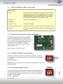
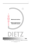
usbLOGiC USB-AV-Player
USB-C20
Für Mercedes Benz
Comand 2.0, Comand APS CD
und Comand APS 220
Navigationssysteme
Produktfeatures
• USB-Schnittstelle für USB-Medien bis zu 2TB (2000GB)
• unterstützt FAT32 und NTFS formatierte Datenträger
• Multipartionsfähig
• Kompatibel mit MP3, AVI, VOB, MOV, RMVB, JPG und vielen mehr
• Last Position Memory
• Integration in und Steuerbar über das Werks-Infotainment
• AV-Eingang mit IR-Steuerkanal
• Optionale Steuerung von After-Market Geräten (z.B. DVD-Player, USB/iPod Geräte, …)
über Werks-Navigationstasten
• After-Market Rückfahrkamera-Eingang
• Automatische Umschaltung auf Rückfahrkamera-Eingang (nur im usbLOGiC-Modus)
• Rückfahrkamerastromversorgungsausgang (+12V max. 1A)
• Rear-Seat-Entertainment AV-Ausgang
• Optional erhältliche IR-Fernbedienung für volle USB-Funktionen/Rear-SeatEntertainment
• Schaltausgang(+12V max. 1A) für angeschlossene Geräte
• TV-Freischaltungsfunktion
Version 27.06.2011
USB-C20
Inhaltsverzeichnis
1. Vor der Installation
1.1.
1.2.
1.3.
1.3.1.
1.3.2.
Lieferumfang
Überprüfung der Kompatibilität mit Fahrzeug und Zubehör
Einstellen der Dip-Schalter der USB-Box USBC-M500
Automatische Umschaltung auf eine Rückfahrkamera
Deaktivierung des usbLOGiC AV-Eingangs
2. Anschluss Schema
3. Installation
3.1.
3.2.
3.3.
3.4.
3.4.1.
3.4.2.
3.4.3.
3.4.4.
Verbindungen zum Comand
Verbindung USB-Box und Kabelsätze
USB und optionales IR-Fernbedienungsset
Anschluss von Peripheriegeräten
AV-Quelle
Installation zusätzlicher IR-Sensor der AV-Quelle
After-Market Rückfahrkamera
After-Market Rear-Seat-Entertainment
4. Bedienung
4.1.
4.2.
4.3.
4.4.
4.5.
4.6.
4.7.
Aktivierung der TV-Freischaltungsfunktion
usbLOGiC als aktuelle AV-Quelle anwählen
Umschalten zwischen internem USB und AV-Quelle
Gerätesteuerungsebene der angeschlossenen AV-Quelle belegen
Belegungstabelle
Bildeinstellungen
Audioeinstellungen
5. Technische Daten
6. Anschlüsse (USB-Box)
7. Technischer Support
Seite
1
Anhang A – Gerätesteuerungstabelle
Anhang B – Übersicht USB Funktionen
Version 27.06.2011
USB-C20
Rechtlicher Hinweis
Der Fahrer darf weder direkt noch indirekt durch bewegte Bilder während der Fahrt
abgelenkt werden. In den meisten Ländern/Staaten ist dieses gesetzlich verboten. Wir
schließen daher jede Haftung für Sach- und Personenschäden aus, die mittelbar sowie
unmittelbar durch den Einbau sowie Betrieb dieses Produkts verursacht wurden. Dieses
Produkt ist, neben dem Betrieb im Stand, lediglich gedacht zur Darstellung stehender Menüs
(z.B. MP3 Menü von DVD-Playern) oder Bilder der Rückfahrkamera während der Fahrt.
Veränderungen/Updates der Fahrzeugsoftware können die Funktionsfähigkeit des Interface
beeinträchtigen. Softwareupdates für unsere Interfaces werden Kunden bis zu einem Jahr
nach Erwerb des Interface kostenlos gewährt. Zum Update muss das Interface frei
eingeschickt werden. Kosten für Ein- und Ausbau werden nicht erstattet.
1. Vor der Installation
Vor der Installation sollte dieses Manual durchgelesen werden. Für die Installation sind
Fachkenntnisse notwendig. Der Installationsort muss so gewählt werden, dass die Produkte
weder Feuchtigkeit noch Hitze ausgesetzt sind.
1.1.
Lieferumfang
SW-Stand und HW-Stand der Interface-Boxen notieren. Manual aufbewahren für
Support-Zwecke!
Kabelsatz
C2C-MB20
Kabelsatz
C3C-AV
USB-Box
USBC-M500
HW_____ SW_____
USB-Verlängerungskabel
USB-EXT
Wenn die Fernbedienung für ein Peripheriegerät genutzt werden soll, werden zusätzliche IRAV-Quelle .
Seite
2
Steuerkabel und Y-Adapter benötigt, siehe Kapitel
Version 27.06.2011
USB-C20
1.2.
Überprüfung der Kompatibilität mit Fahrzeug und Zubehör
Voraussetzungen
Fahrzeug
Mercedes Benz C-Klasse (W203) bis 04/2004, CL-Klasse (C215) ab
09/2002 bis 09/2003, CLK-Klasse (C208 W208) alle MJ, CLK-Klasse
(C209 W209) bis 05/2004 , E-Klasse (W210) alle MJ , G-Modell
(W463) alle bis 03/2007, ML-Klasse (W163) alle MJ, S-Klasse
(W220) ab 09/2002 bis 09/2003, SL-Klasse (R230) bis 06/2004
Navigation
Comand 2.0, Comand APS CD
Einschränkungen
Werks-TV-Tuner
Darf NICHT installiert sein.
After-Market Rückfahrkamera
Die automatische Umschaltung auf die Kamera funktioniert nur
im usbLOGiC-Modus.
USB-Anschluss
Nur für Medien, die mit Stromversorgung über EINEN einzelnen
USB-Stecker funktionieren.
1.3.
Einstellen der Dip-Schalter der USB-Box USBC-M500
Die Werkseinstellung der DIP-Schalter der
USB-Box müssen nur verändert werden, wenn
eine After-Market Rückfahrkamera angeschlossen
werden soll/ist oder der AV-Eingang des usbLOGiC
deaktiviert werden soll. Die DIP-Schalter befinden
sich innerhalb der USB-Box. Für Änderungen ist
es notwendig, die Box zu öffnen.
Die Werkseinstellung ist:
Seite
3
Dip1 = ON, Dip2 = OFF, Dip3 = ON
Version 27.06.2011
USB-C20
1.3.1. Automatische Umschaltung auf eine Rückfahrkamera
Wenn eine After-Market Rückfahrkamera angeschlossen werden soll,
Dip 2 auf ON (oben) schalten, damit der usbLOGiC beim Einlegen des
Rückwärtsganges automatisch auf den Kamera-Eingang umschaltet.
Dip-Schalter
der USB-Box
Hinweis: Die automatische Umschaltung einer After-Market Kamera funktioniert nur im
usbLOGiC Modus.
1.3.2. Deaktivierung des usbLOGiC AV-Eingangs
Dip-Schalter
der USB-Box
Seite
4
Wenn keine periphere AV-Quelle an das usbLOGiC angeschlossen
werden soll, wird empfohlen, den AV-Eingang auszuschalten, um zu
vermeiden, dass der Kunde durch Umschalten aus Versehen ein
schwarzes/kein Bild hat. Um den AV Eingang des usbLOGiC zu
deaktivieren, Dip1 auf OFF (unten) schalten.
Version 27.06.2011
USB-C20
2. Anschluss Schema
Version 27.06.2011
USB-C20
Seite
Zündung ausstellen und Fahrzeugbatterie nach Werksangaben abklemmen! Darf gemäß
Werksangaben die Fahrzeugbatterie nicht abgeklemmt werden, reicht es in den meisten
Fällen aus, das Fahrzeug in den Sleep-Modus zu versetzen. Sollte dieses nicht
funktionieren, kann die Fahrzeugbatterie mit einer Widerstandsleitung abgeklemmt
werden.
5
3. Installation
3.1.
Verbindungen zum Comand
Installationsort ist hinter dem Comand. Die Head-Unit aus dem Armaturenbrett ausbauen.
Die Hülse der 18-Pin AMP-Buchse des C2C-MB20 entfernen.
Pin 2 (rosa), 11 (gelb) und 3 (schwarz) der 18-Pin AMP-Buchse des C2C-MB20 in die
entsprechenden Slots der 18-Pin AMP-Buchse des Werks-Kabelsatzes übertragen.
Sind diese belegt, Werks-Kabel entfernen und isolieren (vor dem Entfernen Notizen
machen).
Pin 17 (blau) und 18 (gelb) der 18-Pin AMP-Buchse des C2C-MB20 in die
entsprechenden Slots der 18-Pin AMP-Buchse des Werks-Kabelsatzes übertragen.
Sind diese belegt, zusätzlich mit den Werks-Kabeln verbinden
Wenn vorhanden, Pin 5 und Pin 6 der 8-Pin C1-Buchse des Werks-Kabelsatzes in die
entsprechenden Slots der 8-Pin C1-Buchse des C2C-MB20 übertragen. Wenn
vorhanden, bleiben die anderen Pins im Werks-Stecker.
C1
C2
Das lose rote Kabel des C2C-MB20 mit Pin 4
der Kammer A verbinden
(+12V Batteriestrom).
Das lose schwarze Kabel des C2C-MB20 mit Pin
8 der Kammer A verbinden (Masse).
B
18-Pin AMP-Buchse des Fahrzeug Kabelsatzes
mit dem C2-Slot des System-Steckers des
A
Comand verbinden.
8
Seite
6
8-Pin C1-Buchse des Kabelsatzes C2C-MB20
4
mit dem C1-Slot des System-Steckers des Comand verbinden.
Version 27.06.2011
USB-C20
3.2.
Verbindung USB-Box und Kabelsätze
Kabelsatz C3C-AV mit 6-Pin Molex der USB-Box USBC-M500 verbinden.
Kabelsatz C2C-MB20 mit 14-Pin Molex der USB-Box USBC-M500 verbinden.
Seite
7
18-Pin AMP-Buchse des C2C-MB20 mit 18-Pin AMP-Stecker der USB-Box USBC-M500
verbinden.
Version 27.06.2011
USB-C20
3.3.
USB und optionales IR-Fernbedienungsset
Den USB-Anschluss des USB-Verlängerungskabels USBC-EXT mit der USB-Box USBCM500 verbinden und die Buchse des USBC-EXT an einem gut erreichbaren Ort, z.B. im
Handschuhfach, installieren. Dabei Sicherstellen, dass genügend Platz vorhanden ist,
um die USB-Medien zu laden.
Installations-Buchse für den Anschluss von USB-Medien.
Das USB-IRSET beinhaltet den externen IR-Sensor C3C-SENSOR und die IRFernbedienung USBC-RC und kann, zusätzlich zur Steuerung durch die
Navigationstasten, zur Steuerung der usbLOGiC internen USB-Funktionen verwendet
werden. Den C3C-SENSOR mit der schwarz/rot/blauen 3-Pin AMP-Buchse des
Kabelsatzes C3C-AVIR verbinden und an einem gut erreichbaren Ort positionieren.
3.4.
Anschluss von Peripheriegeräten
Version 27.06.2011
USB-C20
Seite
Vor der endgültigen Installation der Peripheriegeräte empfehlen wir einen Testlauf der
usbLOGiC-Funktionen, um eine Inkompatibilität mit Fahrzeug, Navigation, Werkszubehör
oder Peripheriegeräten frühestmöglich zu erkennen.
8
Es ist möglich, eine After-Market AV-Quelle, eine After-Market Rückfahrkamera und RearSeat-Entertainment an den usbLOGiC anzuschließen.
3.4.1. AV-Quelle
Der usbLOGiC hat die Möglichkeit, ein vorprogrammiertes Gerät anzuschließen und über die
Navigationstasten zu steuern. Die Geräteliste in der Gerätesteuerungstabelle (Anhang A)
zeigt die vorprogrammierten Steuerkanäle und die gerätespezifischen IR-Steuerkabel
STA-xxx, die separat für jedes zu steuernde Gerät bestellt werden müssen.
Mit entsprechendem STA-xxx IR-Steuerkabel, die gelbe 3-Pin AMP Buchse des
Kabelsatzes C2C-MB20 und den IR-Port der AV-Quelle verbinden.
Mit Cinch-Leitungen, die Cinch-Buchsen AV-IN der USB-Box USBC-M500 mit dem AVAusgang der AV-Quelle verbinden.
Das rosa ACC-Ausgangskabel (+12V max 1A) des Kabelsatzes C2C-MB20 kann mit den
ACC-Schalteingängen der angeschlossenen Geräte verbunden werden, um diese
einzuschalten. Es liegen +12V an, sobald die Head-Unit eingeschaltet ist.
3.4.2. Installation zusätzlicher IR-Sensor der AV-Quelle
Seite
9
Es besteht zusätzlich zur Gerätesteuerung über die Navigation die Möglichkeit, den Original
IR-Sensor des angeschlossenen Gerätes zu installieren. Über einen Y-Adapter (z.B. STAY35MM oder STA-RJ12) für den IR-Port des angeschlossenen Gerätes kann die Steuerung der
Navigation UND der IR-Sensor des Gerätes angeschlossen und gleichzeitig genutzt werden.
Die Installation eines zusätzlichen IR-Sensors empfiehlt sich, da über die Navigationstasten
nur die wichtigsten Funktionen bedient und nicht alle Funktionen erfasst werden können.
Version 27.06.2011
USB-C20
3.4.3. After-Market Rückfahrkamera
Den Video-Cinch der After-Market-Rückfahrkamera mit der Cinch-Buchse R-CAM IN
der USB-Box USBC-M500 verbinden.
Das grüne Kabel des Kabelsatzes C2C-MB20 mit dem Stromanschluss der Kamera
verbinden (+12V max 1A). Das grüne Kabel führt Strom (+12V), wenn der
Rückwärtsgang eingelegt ist.
Hinweis: Die automatische Umschaltung auf die Rückfahrkamera funktioniert nur im
usbLOGiC-Modus.
3.4.4. After-Market Rear-Seat-Entertainment
Version 27.06.2011
USB-C20
Seite
Hinweis: Da der Ausgang vollwertig ist, d.h. das Video-Signal nicht mit dem für das
Navigationssystem geteilt wird, kann die Aufteilung des Video-Signals mit einem
Cinch-Y-Kabel ein ausreichend gutes Bild für zwei Rear-Seat-Entertainment-Monitore
ergeben. Wenn nicht, oder wenn mehr als zwei Monitore angeschlossen werden,
muss ein Video-Signalverteiler verwendet werden.
10
Mittels Cinch-Kabel, das Rear-Seat-Entertainment mit der Cinch-Buchse VIDEO OUT
der USB-Box USBC-M500 verbinden.
4. Bedienung
4.1.
Aktivierung der TV-Freischaltungsfunktion
Das Video-Signal des usbLOGiC wird auch während der Fahrt angezeigt.
Hinweis: Bei Fahrzeugen mit vorab installiertem Werks-TV-Tuner kann eine zusätzliche TVFreischaltung notwendig sein. Es ist nicht möglich, dieses vor der Prüfung zu bestimmen.
4.2.
usbLOGiC als aktuelle AV-Quelle anwählen
Die TV Taste des Comand drücken, um den usbLOGiC als aktuelle AV-Quelle anzuwählen.
4.3.
Umschalten zwischen internem USB und AV-Eingang
Nachdem der usbLOGiC als aktuelle AV-Quelle ausgewählt wurde, den rechten Drehregler
lange oder die Taste „5“ für 3 Sekunden drücken, um zwischen USB und AV-Eingang
umzuschalten.
Hinweis: Wenn der AV-Eingang deaktiviert ist (siehe Kapitel „Deaktivierung des usbLOGiC
AV-Eingangs“), ist es nicht möglich, auf den AV-Eingang AV-IN umzuschalten.
4.4.
Gerätesteuerungsebene der angeschlossenen AV-Quelle belegen
Nachdem der usbLOGiC als aktuelle AV-Quelle
ausgewählt wurde, auf den AV-Eingang des usbLOGiC
umschalten. Anschließend Taste “1” lange drücken oder
die “RET”-Taste kurz drücken. Das Display zeigt “TV2”
und “RC01”. Den rechten Drehregler so lange drehen,
bis der in der Gerätesteuerungstabelle angegebene
gerätspezifische IR-Code (Anhang A) angezeigt wird.
Durch Drücken des rechten Drehreglers die Auswahl
bestätigen.
Wenn das Fahrzeug kein MFA-Display im Armaturenbrett hat, müssen die Raster beim
Drehen des Knopfs gezählt werden (nach rechts +1, nach links -1). Gleichzeitig dabei
beachten, dass der Startpunkt Kanal RC01 ist (das erste Raster nach rechts ist dann bereits
RC02).
Seite
11
Hinweis: Wenn der AV-Eingang deaktiviert ist (siehe Kapitel „Deaktivierung des usbLOGiC
AV-Eingangs“), ist es nicht möglich, die Gerätesteuerung zu belegen.
Version 27.06.2011
USB-C20
4.5.
Belegungstabelle
Die Belegungstabelle zeigt, welche Funktionen des usbLOGiC und des zusätzlich
angeschlossenen Gerätes über die Comand Tasten ausgeführt werden können. Sobald USB
oder der AV-Eingang aktiviert ist, wird durch die Comand Taste in der linken Spalte, die in
der Belegungstabelle ausgeführte Funktion des Gerätes ausgeführt. Die Beschreibung der
Funktion entspricht den Tasten der Fernbedienung des usbLOGiC bzw. des angeschlossenen
Gerätes. Bei den angeschlossenen Geräten kann die Tastenbezeichnung auf der
Fernbedienung variieren (z. B. AV statt Source).
Belegungstabelle usbLOGiC Comand 2.0/APS CD/APS 220
DVB-T
Tuner
AUTO
DVD-Player
iPod®Steuerung
PLAY/PAUSE
Analog-Tuner
PLAY
DVDWechsler
PLAY
2
↑
↑
↑
↑
↑
VOL +
3
EXIT
4
←
EPG
STOP
STOP
POWER
FM
←
←
←
←
CH -
4 long
SOURCE
INFO
DISPLAY
DISPLAY
5
OK
OK
OK
ENTER
MODE
6
OK /
PLAY
→
→
→
→
→
CH +
6 long
AUDIO
AUDIO
AUDIO
AUDIO
MUTE
FM
7
MEDIA
EXIT
PBC
DISC
SHUFFLE
MUTE
SUB
SUB
7 long
SCAN
DISPLAY
MUTE
8
↓
↓
↓
↓
↓
VOL -
9
SETUP
MENU
SETUP
SETUP
LIGHT
ADJUST
11
AV
AV
EJECT
DISPLAY
11 long
POWER
POWER
POWER
POWER
CH +
14
TRACK +
CH +
TRACK +
TRACK +
TRACK +
15
TRACK -
CH -
TRACK -
TRACK -
TRACK -
CH -
16
OK
OK
OK
ENTER
MODE
17
OK /
PLAY
TRACK -
CH -
TRACK -
TRACK -
TRACK -
CH -
18
TRACK +
CH +
TRACK +
TRACK +
TRACK +
CH +
Zusätzlich zu den Head-Unit Tasten können die Lenkradtasten HOCH und RUNTER für
Fernbedienungsfunktionen genutzt werden. Die RUNTER Taste hat die gleiche Funktion wie
“17” und die HOCH-Taste hat die gleiche Funktion wie “18” der Head-Unit.
Version 27.06.2011
USB-C20
12
Interner
USB
POWER
Seite
COMAND
Taste
1
4.6.
Bildeinstellungen
Durch Drücken der Taste “10” ist es möglich, zwischen
den Bildformaten 4:3 und 16:9 umzuschalten (Nur
möglich beim Comand APS CD/220). Durch
langes Drücken der Taste “13” öffnet sich das
Bildeinstellungsmenü.
Das Bildeinstellungsmenü öffnet immer mit den
Einstellungen der Helligkeit. Der jeweils aktuelle
Bildwert wird im Armaturenbrett angezeigt.
Durch Drücken des rechten Knopfs kann von
Helligkeit zu Farbe und Kontrast umgeschaltet
werden (nach Kontrast startet das Interface
wieder mit Helligkeit).
Durch Drehen des rechten Knopfs kann
der jeweilige Bildwert verändert werden.
Das Menü durch Drücken der “13”-Taste
verlassen.
4.7.
Audioeinstellungen
Seite
13
Taste 12 drücken, um in die Audioeinstellungen des Comand zu gelangen.
Version 27.06.2011
USB-C20
5. Technische Daten
Spannungs-Arbeitsbereich
Ruhestrom
Arbeitsstrom
Leistungsaufnahme
Belastbarkeit USB-Port
Temperaturbereich
Gewicht
Abmessungen (nur Box) B x H x T
10.5 – 14.8V
<1mA
min. 450mA/max. 950mA
min. 6W/max. 13W
0,5A dauerhaft (0,8A max)
-30°C bis +80°C
312g
135 x 30 x 105 mm
6. Anschlüsse (USB-Box)
7. Technischer Support
Caraudio-Systems Vertriebs GmbH
Hersteller/Distribution
Rheinhorststr. 22
D-67071 Ludwigshafen am Rhein
NavLinkz GmbH
Vertrieb/Techn. Händler-Support
Eurotec-Ring 45
D-47445 Moers
Tel
+49 180 3 907050*
Email [email protected]
* 7,6cent/Minute aus dem dt. Festnetz, vom dt. Mobilfunk je nach Provider mehr.
Seite
14
Rechtlicher Hinweis: Hier genannte Firmen- und Markenzeichen sowie Produktnamen, sind eingetragene
Warenzeichen ® und somit Eigentum der jeweiligen Rechteinhaber.
Version 27.06.2011
USB-C20
usbLOGiC USB-AV-Player
USB-C20
For navigation systems
Mercedes Benz
Comand 2.0, Comand APS CD
and Comand APS 220
Product features
• USB-port for media up to 2 TB (2000GB)
• supports FAT32 and NTFS formatted media
• multi partition capable
• compatible with MP3, AVI, VOB, MOV, RMVB, JPG and many more
• last position memory
• integrated into and controllable by vehicle infotainment
• AV-input with IR-control channel
• control of after-market devices by OEM buttons, e.g. DVD-player, USB/iPod devices, …
• after-market rear-view camera input
• automatic switching to rear-view camera input (only from usbLOGiC mode)
• rear-view camera power (+12V max. 1A)
• rear-seat-entertainment AV-output
• optional remote control for full USB functions/rear-seat-entertainment
• power on remote out trigger signal (+12V max. 1A) to switch on connected devices
• video-in-motion
Version 27.06.2011
USB-C20
Contents
1. Prior to Installation
1.1.
1.2.
1.3.
1.3.1.
1.3.2.
Delivery contents
Check compatibility of vehicle and accessories
Setting the dip switches of the USB-box USBC-M500
Automatic switching to rear-view camera
Deactivating usbLOGiC AV-input
2. Connection schema
3. Installation
3.1.
3.2.
3.3.
3.4.
3.4.1.
3.4.2.
3.4.3.
3.4.4.
Connections to the Comand
Interconnecting USB-box and harnesses
USB and optional IR-remote control set
Connecting peripheral devices
AV-source
Installing AV-source’s IR-sensor additionally
After-market rear-view camera
After-market rear-seat-entertainment
4. Operation
4.1.
4.2.
4.3.
4.4.
4.5.
4.6.
4.7.
Activation of the video-in-motion function
Selecting the usbLOGiC as current AV-source
Switching between internal USB and AV-input
Assigning device control for connected AV-source
Button assignment table
Picture settings
Audio settings
5. Specifications
6. Connections (USB-box)
7. Technical support
Page
1
Appendix A – Device control table
Appendix B – USB function manual
Version 27.06.2011
USB-C20
Legal Information
By law, watching moving pictures while driving is prohibited, the driver must not be
distracted. We do not accept any liability for material damage or personal injury resulting,
directly or indirectly, from installation or operation of this product. This product should only
be used while standing or to display fixed menus or rear-view-camera video when the
vehicle is moving, for example the MP3 menu for DVD upgrades.
Changes/updates of the vehicle’s software can cause malfunctions of the interface. We
offer free software-updates for our interfaces for one year after purchase. To receive a free
update, the interface must be sent in at own cost. Labor cost for and other expenses
involved with the software-updates will not be refunded.
1. Prior to installation
Read the manual prior to installation. Technical knowledge is necessary for installation. The
place of installation must be free of moisture and away from heat sources.
1.1.
Delivery contents
Take down the SW-version and HW-version of the interface boxes, and store this
manual for support purposes.
Harness
C2C-MB20
Harness
C3C-AV
USB-box
USBC-M500
HW_____ SW_____
USB-installation socket USBC-EXT
If remote function for a peripheral device shall be used, additionally an IR-
Page
2
remote cable and Y-adapter are needed, see chapter AV-source .
Version 27.06.2011
USB-C20
1.2.
Check compatibility of vehicle and accessories
Requirements
Vehicle
Mercedes Benz C-Class (W203) til 04/2004, CL-Class (C215) from
09/2002 til 09/2003, CLK-Class (C208 W208) all years, CLK-Class
(C209 W209) til 05/2004 , E-Class (W210) all years , G-Modell
(W463) til 03/2007, ML-Class (W163) all jears, S-Class (W220)
from 09/2002 til 09/2003, SL-Class (R230) til 06/2004
Navigation
Comand 2.0, Comand APS CD
Limitations
Factory-TV-tuner
Must NOT be installed.
After-market rear-view cam
Automatic switching to camera only works from usbLOGiC mode
USB-port
Only for media which work with power supply by ONE single USB
connector.
1.3.
Setting the dip switches of the USB-box USBC-M500
The default dip switch settings of the USB-box
need to be changed ONLY if an after-market
rear-view camera shall be connected or if the AV
of the usbLOGiC shall be deactivated. The dip
switches are located inside the USB-box.
For changes it is necessary to open the box.
Default settings are:
dip1 = ON, dip2 = OFF, dip3 = ON
1.3.1. Automatic switching to rear-view camera
If an after-market rear-view camera shall be connected, in order for
the usbLOGiC to automatically switch to its camera input on engaged
reverse gear,
set dip2 = ON (up).
Dip switches
of USB-box
Note: With after-market cameras, automatic switching works only from
usbLOGiC mode.
1.3.2. Deactivating usbLOGiC AV-input
Dip switches
of USB-box
Version 27.06.2011
Page
3
If no peripheral AV-source shall be connected to the usbLOGiC, we
recommend to disable the AV-input, to avoid customers switching by
mistake to black/no picture of the AV-input. In order to disable the
AV-input of the usbLOGiC,
set dip1 = OFF (down).
USB-C20
2. Connection schema
Version 27.06.2011
USB-C20
Page
Switch off ignition and disconnect the vehicle’s battery! If according to factory rules
disconnecting the battery has to be avoided, it is usually sufficient to put the vehicle in
sleep-mode. In case the sleep-mode does not show success, disconnect the battery with a
resistor lead.
4
3. Installation
3.1.
Connections to the Comand
Place of installation is behind the Comand. Remove the head-unit from the dash-board.
Remove shell from female 18pin AMP connector of C2C-MB20.
Transfer pins 2 (pink), 11 (yellow) and 3 (black) from female 18pin AMP connector of
C2C-MB20 to corresponding slots of female 18pin AMP connector of factory harness.
If occupied remove and isolate factory wires (take notes before removing).
Transfer pins 17 (blue) and 18 (yellow) from female 18pin AMP connector of C2CMB20 to corresponding slots of female 18pin AMP connector of factory harness. If
occupied connect additionally to the factory wires.
If existing transfer pins 5 and 6 from female 8pin C1 connector of factory harness to
corresponding slots of female 8pin C1 connector of C2C-MB20. If existing, other pins
remain in the factory connector.
C1
C2
Connect loose red wire of C2C-MB20 to pin 4
of chamber A (+12V battery power).
Connect loose black wire of C2C-MB20 to pin 8
of chamber A (ground).
Plug female 18pin AMP connector of vehicle
harness into C2 slot of Comand’s male
system connector.
A
4
8
Page
5
Plug female 8pin C1 connector of harness
C2C-MB20 into C1 slot of Comand’s male
system connector.
B
Version 27.06.2011
USB-C20
3.2.
Interconnecting USB-box and harnesses
Plug harness C3C-AV into 6pin Molex of USB-box USBC-M500.
Plug harness C2C-MB20 into 14pin Molex of USB-box USBC-M500.
Page
6
Plug female 18pin AMP-connector of C2C-MB20 into male 18pin AMP-socket of
USB-box USBC-M500.
Version 27.06.2011
USB-C20
3.3.
USB and optional IR-remote control set
Connect USB-connector of USB-installation socket USBC-EXT to USB-socket of USBbox USBC-M500 and install the USBC-EXT socket in a well accessible location, e.g. the
glove-box. Make sure there is enough space to load USB-media.
Installation socket for the connection of USB-media.
The USB-IRSET consists of the external C3C-SENSOR IR-sensor and the USBC-RC IRremote control and can be used to control the usbLOGiC’s internal USB functions
additionally to the control through the navigations buttons. Connect the C3C-SENSOR
to the female black/red/blue 3pin AMP connector of harness C3C-AVIR and locate the
sensor in an accessible place.
3.4.
Connecting peripheral devices
It is possible to connect an after-market AV-source, an after-market rear-view camera and
rear-seat-entertainment to the usbLOGiC.
Page
7
Before final installation of the peripheral devices, we recommend to test-run the usbLOGiC
functions to detect incompatibility of vehicle, navigation, factory accessories or peripheral
devices as soon as possible.
Version 27.06.2011
USB-C20
3.4.1. AV-source
The usbLOGiC has the possibility to connect and remotely control by navigation buttons a
pre-programmed device. The device list in the device control table (appendix A) shows the
pre-programmed remote channels and the related IR-remote cables STA-xxx which must be
ordered separately for the control of the device.
Using the respective STA-xxx IR-control cable, interconnect the yellow female 3pin
AMP connector of harness C2C-MB20 and the IR-port of the AV-source.
Using an RCA-cable, interconnect the female RCA-port AV-IN of the USB-box
USBC-M500 with the AV-output of the AV-source.
The pink ACC-output wire (+12V max 1A) of harness C2C-MB20 can be connected to
the ACC-input wires of the connected device to switch it on. It carries +12V when the
head-unit is running.
3.4.2. Installing AV-source’s IR-sensor additionally
Page
8
Additionally to the control via OEM navigation, it is possible to install the original IR-sensor
of a connected device. By using the respective Y-adapter (e.g. STA-Y35MM or STA-RJ12) for
the IR-Port of the connected device, the controls of navigation AND device’s IR-sensor can be
connected and used simultaneously. Installation of the IR-sensor is recommended as the
controls via navigation are limited, and not all functions may be covered.
Version 27.06.2011
USB-C20
3.4.3. After-market rear-view camera
Connect the video RCA of the after-market rear-view camera to female
RCA connector R-CAM IN of USB-box USBC-M500.
Connect the green wire of C2C-MB20 to the camera power supply (+12V max 1A)
The green wire is high (+12V) when reverse gear is engaged.
Note: Automatic switching to camera only works from usbLOGiC mode.
3.4.4. After-market rear-seat-entertainment
Version 27.06.2011
USB-C20
Page
Note: As the output is a full output, not shared with the video signal for the
navigation system, splitting the video with an RCA Y-cable might give a good enough
picture for two rear-seat-entertainment monitors. If not, or if connecting more than
two monitors, use a video splitter.
9
Using RCA-cables, connect the rear-seat-entertainment to the female RCA-connector
VIDEO OUT of USB-box USBC-M500.
4. Operation
4.1.
Activation of the video-in-motion function
The video of the usbLOGiC is displayed also in motion.
Note: On vehicles with previously installed factory TV-tuner an extra video-in-motion
interface might be necessary. It is not possible to determine this prior to testing.
4.2.
Selecting the usbLOGiC as current AV-source
Push TV button of Comand to choose the usbLOGiC as current AV-source.
4.3.
Switching between internal USB and AV-input
After selecting the usbLOGiC as current AV source, longpress the right knob or the
“5”-button 3 seconds to switch between USB and AV-input. Repeat to switch back.
Note: If the AV-input is deactivated (see chapter “Deactivating usbLOGiC AV-input”), it is not
possible to switch to the usbLOGiC’s AV-input AV-IN.
4.4.
Assigning device control for connected AV-source
After selecting the usbLOGiC as current AV source,
switch to the usbLOGiC’s AV-input. Now longpress
number the“1”-button or shortpress the “RET”-button.
The display in the instruments will show “TV 2” and
“RC01”. Turn right knob until the device-related IR-code
as described in device control table (appendix A) is
reached. Push right knob to confirm
the assignment.
If the vehicle has no MFD display in the instrument panel, you must count the notches when
turning the knob (to the right +1, to the left -1). At the same time, remember that the
starting point is channel RC01 (the first notch to the right is then already RC02).
Page
10
Note: If the AV-input is deactivated (see chapter “Deactivating usbLOGiC AV-input”), it is not
necessary, nor possible to assign device controls.
Version 27.06.2011
USB-C20
4.5.
Button assignment table
The button assignment table shows which functions of usbLOGiC and additionally connected
devices can be executed by Comand buttons. Once USB or AV-input mode is activated, the
Comand button in the left column will execute the function described in the corresponding
device column. The function description equals the remote control buttons of the optional
usbLOGiC remote control or the additional device. On the additional device the writing may
vary (e.g. AV instead of Source).
Button assignment table usbLOGiC Comand 2.0/APS CD/APS 220
DVB-T
tuners
AUTO
DVD-player
iPod®-control
PLAY
DVDchanger
PLAY
2
↑
↑
3
EXIT
4
←
4 long
5
PLAY/PAUSE
SCAN
↑
↑
↑
VOL +
EPG
STOP
STOP
POWER
FM
←
←
←
←
CH -
SOURCE
INFO
DISPLAY
DISPLAY
OK
OK
OK
ENTER
MODE
6
OK /
PLAY
→
→
→
→
→
CH +
6 long
AUDIO
AUDIO
AUDIO
AUDIO
MUTE
FM
7
MEDIA
EXIT
PBC
DISC
SHUFFLE
MUTE
SUB
SUB
7 long
Analog-tuner
DISPLAY
MUTE
8
↓
↓
↓
↓
↓
VOL -
9
SETUP
MENU
SETUP
SETUP
LIGHT
ADJUST
AV
AV
EJECT
DISPLAY
11
11 long
POWER
POWER
POWER
POWER
14
TRACK +
CH +
TRACK +
TRACK +
TRACK +
CH +
15
TRACK -
CH -
TRACK -
TRACK -
TRACK -
CH -
16
OK
OK
OK
ENTER
MODE
17
OK /
PLAY
TRACK -
CH -
TRACK -
TRACK -
TRACK -
CH -
18
TRACK +
CH +
TRACK +
TRACK +
TRACK +
CH +
Additionally to the head-unit buttons, the steering-wheel buttons UP and DOWN can be
used for remote functions. DOWN-button has the same function as 17 on the head-unit and
UP-button has the same function as 18 on the head-unit.
Version 27.06.2011
USB-C20
11
Internal
USB
POWER
Page
COMAND
button
1
4.6.
Picture settings
By pressing the button 10, it is possible to switch
between 4:3 and 16:9 picture format
(Only possible on Comand APS CD/220).
To enter the picture settings menu longpress button 13.
The picture settings menu always starts with the
brightness settings. The respective current picture
value is displayed on the instrument panel.
Press the right knob to change from brightness to
colour and contrast (after contrast, the interface
starts again with brightness).
Turn the right knob to change the current picture
value. To quit the settings menu press button 13.
4.7.
Audio settings
To enter the Comand’s audio settings menu press button 12.
5. Specifications
Operation voltage
Stand-by power drain
Operation power drain
Power consumption
Power rating USB-port
Temperature range
Weight
Measurements (box only) B x H x T
10.5 – 14.8V DC
<1mA
min. 450mA/max. 950mA
min. 6W/max. 13W
0,5A permanent (0,8A max)
-30°C to +80°C
312g
135 x 30 x 105 mm
Page
12
6. Connections (USB-box)
Version 27.06.2011
USB-C20
7. Technical Support
Caraudio-Systems Vertriebs GmbH
manufacturer/distribution
Rheinhorststr. 22
D-67071 Ludwigshafen am Rhein
NavLinkz GmbH
corporate sales/tech dealer-support
Eurotec-Ring 45
D-47445 Moers
phone +49 180 3 907050
email [email protected]
Page
13
Legal disclaimer: Mentioned company and trademarks, as well as product names/codes are registered
trademarks ® of their corresponding legal owners.
Version 27.06.2011
USB-C20