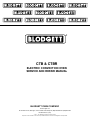
1
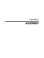
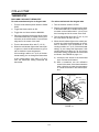
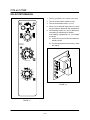
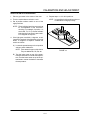
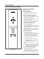
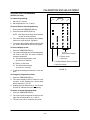
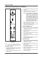
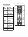
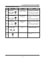
CTB & CTBR
ELECTRIC CONVECTION OVEN
SERVICE AND REPAIR MANUAL
BLODGETT OVEN COMPANY
www.blodgett.com
44 Lakeside Avenue, Burlington, Vermont 05401 USA Telephone (802) 658Ć6600 Fax: (802)864Ć0183
PN 36277 Rev D (7/02)
E 2001 - G.S. Blodgett Corporation All rights reserved.
Duplication of the information in this manual is prohibited without the consent of the Blodgett Service Department.
TABLE OF CONTENTS
1. INTRODUCTION
Oven Specifications . . . . . . . . . . . . . . . . . . . . . . . . . . . . . . . . . . . . . . . . . . . . . . . . . . . . . . . . . . . . . . .
Electrical Specifications . . . . . . . . . . . . . . . . . . . . . . . . . . . . . . . . . . . . . . . . . . . . . . . . . . . . . . . . . . .
1-1
1-2
2. ASSEMBLY
Stand Assembly . . . . . . . . . . . . . . . . . . . . . . . . . . . . . . . . . . . . . . . . . . . . . . . . . . . . . . . . . . . . . . . . . .
Oven Assembly to Stand . . . . . . . . . . . . . . . . . . . . . . . . . . . . . . . . . . . . . . . . . . . . . . . . . . . . . . . . . .
Legs and Casters . . . . . . . . . . . . . . . . . . . . . . . . . . . . . . . . . . . . . . . . . . . . . . . . . . . . . . . . . . . . . . . . .
1-1
1-3
1-4
3. OPERATION
Sequence of Operation . . . . . . . . . . . . . . . . . . . . . . . . . . . . . . . . . . . . . . . . . . . . . . . . . . . . . . . . . . . .
Cook Only - 19031 rev A . . . . . . . . . . . . . . . . . . . . . . . . . . . . . . . . . . . . . . . . . . . . . . . . . . . . . .
Solid State Digital - 33285 rev F . . . . . . . . . . . . . . . . . . . . . . . . . . . . . . . . . . . . . . . . . . . . . . . .
Intelliplus, Intellihold or Intellirack - 21448 rev E . . . . . . . . . . . . . . . . . . . . . . . . . . . . . . . . . .
Blodgett IQ - 33237 rev C . . . . . . . . . . . . . . . . . . . . . . . . . . . . . . . . . . . . . . . . . . . . . . . . . . . . .
Infinite with Pulse Plus - 21062 rev A . . . . . . . . . . . . . . . . . . . . . . . . . . . . . . . . . . . . . . . . . . . .
Two Speed with Integrated Control - 21535 rev D . . . . . . . . . . . . . . . . . . . . . . . . . . . . . . . .
Triple Setpoint Thermostat - 22817 rev C . . . . . . . . . . . . . . . . . . . . . . . . . . . . . . . . . . . . . . . .
Schematics . . . . . . . . . . . . . . . . . . . . . . . . . . . . . . . . . . . . . . . . . . . . . . . . . . . . . . . . . . . . . . . . . . . . . .
Cook Only . . . . . . . . . . . . . . . . . . . . . . . . . . . . . . . . . . . . . . . . . . . . . . . . . . . . . . . . . . . . . . . . . . .
Solid State Digital . . . . . . . . . . . . . . . . . . . . . . . . . . . . . . . . . . . . . . . . . . . . . . . . . . . . . . . . . . . . .
Intelliplus, Intellihold or Intellirack . . . . . . . . . . . . . . . . . . . . . . . . . . . . . . . . . . . . . . . . . . . . . . .
Blodgett IQ . . . . . . . . . . . . . . . . . . . . . . . . . . . . . . . . . . . . . . . . . . . . . . . . . . . . . . . . . . . . . . . . . . .
Infinite with Pulse Plus . . . . . . . . . . . . . . . . . . . . . . . . . . . . . . . . . . . . . . . . . . . . . . . . . . . . . . . . .
Two Speed with Integrated Control . . . . . . . . . . . . . . . . . . . . . . . . . . . . . . . . . . . . . . . . . . . . . .
Triple Setpoint thermostat . . . . . . . . . . . . . . . . . . . . . . . . . . . . . . . . . . . . . . . . . . . . . . . . . . . . . .
3-1
3-1
3-2
3-3
3-4
3-5
3-6
3-7
3-8
3-8
3-9
3-10
3-11
3-12
3-13
3-14
4. CALIBRATION AND ADJUSTMENT
Thermostat . . . . . . . . . . . . . . . . . . . . . . . . . . . . . . . . . . . . . . . . . . . . . . . . . . . . . . . . . . . . . . . . . . . . . .
Solid State Manual . . . . . . . . . . . . . . . . . . . . . . . . . . . . . . . . . . . . . . . . . . . . . . . . . . . . . . . . . . . . . . . .
Solid State Digital Control . . . . . . . . . . . . . . . . . . . . . . . . . . . . . . . . . . . . . . . . . . . . . . . . . . . . . . . . . .
Intellihold and Intelliplus Controls . . . . . . . . . . . . . . . . . . . . . . . . . . . . . . . . . . . . . . . . . . . . . . . . . . .
Intellitouch Control . . . . . . . . . . . . . . . . . . . . . . . . . . . . . . . . . . . . . . . . . . . . . . . . . . . . . . . . . . . . . . . .
Blodgett IQ Control . . . . . . . . . . . . . . . . . . . . . . . . . . . . . . . . . . . . . . . . . . . . . . . . . . . . . . . . . . . . . . .
Blodgett IQ2T Control Factory Level Programming . . . . . . . . . . . . . . . . . . . . . . . . . . . . . . . . . . .
IQ VVCĆ208 Control . . . . . . . . . . . . . . . . . . . . . . . . . . . . . . . . . . . . . . . . . . . . . . . . . . . . . . . . . . . . . . .
Heating Elements Resistance . . . . . . . . . . . . . . . . . . . . . . . . . . . . . . . . . . . . . . . . . . . . . . . . . . . . . .
Probe Resistance vs Temperature . . . . . . . . . . . . . . . . . . . . . . . . . . . . . . . . . . . . . . . . . . . . . . . . . .
4-1
4-3
4-5
4-7
4-8
4-9
4-11
4-12
4-17
4-17
5. TROUBLESHOOTING
Heat System . . . . . . . . . . . . . . . . . . . . . . . . . . . . . . . . . . . . . . . . . . . . . . . . . . . . . . . . . . . . . . . . . . . . .
Display Error Codes . . . . . . . . . . . . . . . . . . . . . . . . . . . . . . . . . . . . . . . . . . . . . . . . . . . . . . . . . . . . . .
Intellitouch . . . . . . . . . . . . . . . . . . . . . . . . . . . . . . . . . . . . . . . . . . . . . . . . . . . . . . . . . . . . . . . . . . .
Intellihold and Intelliplus . . . . . . . . . . . . . . . . . . . . . . . . . . . . . . . . . . . . . . . . . . . . . . . . . . . . . . .
Blodgett IQ Control . . . . . . . . . . . . . . . . . . . . . . . . . . . . . . . . . . . . . . . . . . . . . . . . . . . . . . . . . . . .
5-1
5-3
5-3
5-3
5-3
i
TABLE OF CONTENTS
6. PARTS REPLACEMENT
Door . . . . . . . . . . . . . . . . . . . . . . . . . . . . . . . . . . . . . . . . . . . . . . . . . . . . . . . . . . . . . . . . . . . . . . . . . . . .
Door Interlock Switch . . . . . . . . . . . . . . . . . . . . . . . . . . . . . . . . . . . . . . . . . . . . . . . . . . . . . . . . . . . . .
Window Assembly . . . . . . . . . . . . . . . . . . . . . . . . . . . . . . . . . . . . . . . . . . . . . . . . . . . . . . . . . . . .
Element . . . . . . . . . . . . . . . . . . . . . . . . . . . . . . . . . . . . . . . . . . . . . . . . . . . . . . . . . . . . . . . . . . . . . . . . .
Motor . . . . . . . . . . . . . . . . . . . . . . . . . . . . . . . . . . . . . . . . . . . . . . . . . . . . . . . . . . . . . . . . . . . . . . . . . . .
ii
6-1
6-1
6-1
6-2
6-2
CHAPTER 1
INTRODUCTION
CTB and CTBR
OVEN SPECIFICATIONS
Cooking in a convection oven differs from cooking
in a conventional deck or range oven since heated
air is constantly recirculated over the product by a
fan in an enclosed chamber. The moving air continĆ
ually strips away the layer of cool air surrounding
the product, quickly allowing the heat to penetrate.
The result is a high quality product, cooked at a
lower temperature in a shorter amount of time.
OVEN COMPONENTS
Heating Elements - located on the side of the
oven, the elements provide heat to the baking
chamber on electric ovens.
Control Panel - contains wiring and components
to control the oven operation.
Oven Racks - five racks are provided standard.
Additional racks are available.
Blodgett convection ovens represent the latest adĆ
vancement in energy efficiency, reliability, and
ease of operation. Heat normally lost, is recircuĆ
lated within the cooking chamber before being
vented from the oven: resulting in substantial reĆ
ductions in energy consumption and enhanced
oven performance.
Rack Supports - hold oven racks.
Blower Wheel Cover - located on the side interior
wall of the oven. Protects the blower wheel.
Blower Wheel - spins to circulate hot air in the
baking chamber.
Convection Motor - provides power to turn the
blower wheel.
CTB
CTBR
FIGURE 1
1-1
INTRODUCTION
ELECTRICAL SPECIFICATIONS
Wiring diagrams are located in the blower comĆ
partment area.
1. The supply conduit enters through the rear of
the oven and electrical block secured to the
perforated panel at the back of the control
compartment.
Ovens are supplied for operation in several voltage
choices, single or three phase grounded circuits.
THE BLODGETT OVEN COMPANY CANNOT ASĆ
SUME RESPONSIBILITY FOR LOSS OR DAMAGE
SUFFERED AS A RESULT OF IMPROPER INSTALĆ
LATION.
The electric motor, indicator lights and related
switches are interconnected through the one powĆ
er source supplied to the oven.
Amperes
Volts
Phase
L1
L2
L3
N
Electrical
Connection
AWG*
5.6
208
1
27
-
27
-
8
5.6
208
3
24
12
15
-
10
5.6
220Ć240
1
24
-
24
-
8
5.6
220Ć240
3
21
11
14
-
10
8.0
208
1
35
-
35
-
6
8.0
208
3
22
20
21
-
10
8.0
220Ć240
1
32
-
32
-
6
8.0
220Ć240
3
20
18
19
-
10
5.6
208
1
27
-
27
-
5.6
220-240
1
24
-
-
24
8
220-240
1
35
-
-
35
5.6
220/380
3
10
8
8
2
8
220/380
3
14
12
12
2
5.6
240/415
3
10
7
7
3
8
240/415
3
13
11
11
2
5.6
230/400
3
9
8
8
1
8
230/400
3
13
11
11
2
KW/Section
60 HZ UNITS
50 HZ UNITS
Size per
llocall codes
d
NOTE: *Electric connection wiring is sized for 90_C copper wire at 125% of rated input.
NOTE: Double units can have phase loads partially equalized by matching lines during hookĆup. OtherĆ
wise, CTBĆDouble or CTBRĆDouble load ratings are twice the above data.
1-2
CTB and CTBR
This page intentionally left blank.
1-3
CHAPTER 2
ASSEMBLY
CTB and CTBR
STAND ASSEMBLY
2. Attach one leg to each of the corner stud bolts
on the bottom of the stand top.
STAND OPTIONS
Small Stands Without Shelves
D
D
3. Place a lock washer and nut on each stud, and
tighten securely.
The 5Ć3/4" (15cm) stand is used for a single
oven, when short legs are required for counterĆ
top use.
4. The stand is now ready for the oven assembly.
Stands With Shelves
The 7" (18cm) stand is used for a double
stacked oven, when the oven is to be located
on the floor.
1. Place stand frame upside down on a work surĆ
face.
Stands With Shelves
D
D
2. Attach one leg to each of the corner stud bolts
on the bottom of the stand top.
Three stands, 16" (40cm), 19" (48cm), and 24"
(61cm) are available for different installation reĆ
quirements.
3. Place a lock washer and nut on each bolt, and
tighten. DO NOT tighten leg bolts completely.
The 33" (84cm) stand is used for a single oven
when counter space is limited.
4. Place the shelf between the legs so that the
smooth top surface is facing the top of the stand.
Open Stands With Racks
D
5. Align the shelf holes with the bolt holes found
near the bottom of each leg.
The 24" (61cm) or 33" (84cm) open stands are
available with a rack support system located
below the oven.
6. Insert a carriage bolt from the outside of the
leg, through the leg, and through the shelf corĆ
ner bracket.
STAND ASSEMBLY
Small Stands Without Shelves
7. Place a lock washer and nut on each bolt, and
tighten securely.
1. Place stand frame upside down on a work surĆ
face.
8. Tighten the leg frame bolts.
FIGURE 2
1-1
ASSEMBLY
Open Stands With Racks
1. Lay stand frame top down on the floor as
shown. See FIGURE 3.
6. Place a lock washer and nut on each bolt, and
tighten securely.
2. Position the four leg assemblies and support
angles as shown. Attach with the 5/16Ć18 nuts
provided. DO NOT tighten leg bolts completely.
7. Repeat Steps 3-6 for the top shelf.
NOTE: Be sure the slots in the top shelf are
aligned with the support angles.
NOTE: Be sure the support angles and clips
are located correctly for your oven conĆ
figuration. See FIGURE 3.
8. Insert the top of the rack stops into the two
back clips on the angle supports as shown. InĆ
sert the bottom of the rack stops into the slots
in the top shelf as shown.
3. Position the bottom shelf between the legs so
that the smooth top surface is facing the top of
the stand.
9. Insert the rack supports into the remaining four
clips on the angle supports as shown. Insert
the bottom of the rack supports into the slots
in the top shelf as shown.
4. Align the shelf holes with the bolt holes found
near the bottom of each leg.
5. Insert a carriage bolt from the outside of the
leg, through the leg, and through the shelf corĆ
ner bracket.
10. Tighten all loose bolts.
CTB
Back of Stand
Rack Stop
Support
Angle,
RH
Support
Angle, LH
Rack
Support
CTBR
Back of Stand
Support
Angle
Rack Stop
Top Shelf
(rear)
Support
Angle,
RH
Support
Angle,
LH
Rack
Support
Rack
Support
Attach Rack Supports and Rack Stops
FIGURE 3
1-2
CTB and CTBR
OVEN ASSEMBLY TO STAND
Single Section
Double Section
1. Place the assembled stand in the location
where the oven is going to be used.
1. Assemble the lower section to the stand as deĆ
scribed. DO NOT replace the side control comĆ
partment or close the front control panel.
2. Remove the side control compartment cover
and open the front control panel of a single
oven (or lower section).
2. With a tool, punch out the knockĆouts in the
oven top of the lower oven.
3. With a tool, punch out the knockĆouts in the
oven bottom near each corner.
3. Remove the side control compartment cover
and open the front control panel of the upper
oven.
4. Set the oven on the stand. Center it to the
frame.
4. With a tool, punch out the knockĆouts in the
bottom of the upper oven near each corner.
5. Align the front, and rear bolt holes of the oven
with the bolt holes in the stand.
5. Set the upper oven on the lower oven.
6. Insert a bolt and washer, from the top down
through each of the 2 holes.
6. Align the front, and rear bolt holes of the upper
oven with the bolt holes in the bottom oven.
7. Place a nut and washer on each of the 2 bolts,
and tighten securely.
7. Insert a bolt and washer, from the top down
through each of the 2 holes.
8. Replace the oven's side control compartment,
and close the front control panel.
8. Place a nut and washer on each of the 2 bolts,
and tighten securely.
NOTE: For single section ovens only. For
double stacked ovens step 8 will be
completed once the ovens are stacked.
9. Replace the control compartment cover, and
close the front control panel on both of the
ovens.
FIGURE 5
FIGURE 4
1-3
ASSEMBLY
LEGS AND CASTERS
4" (10CM) LEG ATTACHMENT
OVEN LEVELING
1. Lay the oven on its side.
After assembly, the oven should be leveled and
moved to the operating location.
2. Screw one leg into each of the corner nuts.
1. The oven can be leveled by adjusting the feet
or casters located on the bottom of each leg.
ADJUSTMENTS ASSOCIATED WITH
INSTALLATION
INITIAL
Each oven, and its component parts, have been
thoroughly tested and inspected prior to shipment.
However, it is often necessary to further test or adĆ
just the oven as part of a normal and proper instalĆ
lation. These adjustments are the responsibility of
the installer, or dealer. Since these adjustments are
not considered defects in material or workmanĆ
ship, they are not covered by the Original EquipĆ
ment Warranty. They include, but are not limited to:
FIGURE 6
CASTER INSTALLATION
NOTE: Casters are not supplied for the 4" (10cm)
legs, 5Ć3/4" (15cm) or 7" (18cm) stands.
D
calibration of the thermostat
D
adjustment of the doors
D
leveling
D
tightening of fasteners.
No installation should be considered complete withĆ
out proper inspection, and if necessary, adjustment
by qualified installation or service personnel.
NOTE: Install the locking casters on the front of the
oven. Install the nonĆlocking casters on the
back of the oven.
1. Insert the caster into the leg. Secure the caster
to the leg by tightening the locknut.
FIGURE 7
1-4
CTB and CTBR
This page intentionally left blank.
1-5
CHAPTER 3
OPERATION
CTB and CTBR
SEQUENCE OF OPERATION
NOTE: The following instructions represent the most common controllers. For questions regarding other
options call the Blodgett Service Department at (800)331Ć5842.
COOK ONLY - 19031 REV A
Component Reference
Operation
NOTE: Refer to FIGURE 8 page 3-8 for compoĆ
nent locations.
1. Power is delivered to the mode selector switch
(1) on terminals L1 and N.
1. MODE SELECTOR SWITCH
2. When the mode selector switch is turned to the
ON position power will be delivered to terminal
1 of the timer (2), one terminal of the door
switch (3) and terminal 8 of the cook temperaĆ
ture control (4).
2. TIMER
3. DOOR SWITCH
4. COOK TEMPERATURE CONTROL
3. If the door is closed, the door switch will be
closed sending power to the blower motor (5).
5. BLOWER MOTOR
6. COOK THERMOSTAT
4. If the cook thermostat (6) is calling for heat, a
switch is made between terminal 6 & 7 of the
cook temperature control, sending power to
the cook light (7) and the coil of the contactor
(8), powering up the heating elements (9).
7. COOK LIGHT
8. CONTACTOR
9. HEATING ELEMENTS
NOTE: The temperature probe used has an
ascending temperature coefficient.
3-1
OPERATION
SOLID STATE DIGITAL - 33285 REV F
Component Reference
Operation
NOTE: Refer to FIGURE 9 page 3-9 for compoĆ
nent locations.
1. Power is delivered to terminal N of the mode
selector switch (1). The other leg of power is
not interrupted and will not be discussed.
1. MODE SELECTOR SWITCH
2. If the mode selector switch is closed between
N and terminal 3, one leg of power will be delivĆ
ered to one side of the door switch (2) terminal
J8 of the time and temperature controller (3)
and the axial fan (4).
2. DOOR SWITCH
3. TIME AND TEMPERATURE CONTROLLER
4. AXIAL FAN
5. HIGH LIMIT SWITCH
3. If the door is closed, the door switch must be
closed sending power to the common terminal
of the time and temperature controller.
6. CONTACTOR
7. HEATING ELEMENTS
4. If a temperature is programmed in the time and
temperature controller, a switch is closed beĆ
tween J8 & J9 sending power to one terminal
of a high limit switch 5. If the high limit switch
(5) is closed, power goes to the contactor (6)
closing it. Power then goes to a set of contacts
powering up the heating elements (7).
8. CONVECTION FAN
5. Contacts within the time and temperature conĆ
trol close between terminals common and NO
sending power to the convection fan (8).
NOTE: The temperature probe used for this
application has a descending temperĆ
ature coefficient.
NOTE: When the mode switch is made beĆ
tween N & 2 and L1 and 1 the oven will
be in cool down.
3-2
CTB and CTBR
INTELLIPLUS, INTELLIHOLD OR INTELLIRACK - 21448 REV E
Component Reference
Operation
NOTE: Refer to FIGURE 10 page 3-10 for compoĆ
nent locations.
1. Power is delivered to terminals 1 & N of the
mode selector switch (1). If the mode selector
switch is made between L1 & terminal 1 N &
terminal 2, power goes to one terminal of the
door switch (2), terminal E1 of the controller (3)
and the axial fan (4).
1. MODEL SELECTOR SWITCH
2. DOOR SWITCH
3. CONTROLLER
2. When the door is closed, the door switch must
be closed sending power to the contacts of reĆ
lays E10 of K1, E11 of K2 and E6 of K3 in the
controller. If the controller is powered up and
set for hi or low speed then the contacts of E10
or E11 close sending power to the convection
fan (7).
4. AXIAL FAN
5. CONTACTOR
6. OVEN READY LIGHT
7. CONVECTION MOTOR
3. If a temperature has been programmed into
the controller, the contacts within K1 close
sending power to the contactor (5) and the
oven ready light (6).
NOTE: The temperature probe has an ascendĆ
ing temperature coefficient.
NOTE: All components have one leg of power
as long as the appliance is turned on.
The only exception is the axial fan
which has both legs of potential power.
3-3
OPERATION
BLODGETT IQ - 33237 REV C
Component Reference
Operation
NOTE: Refer to FIGURE 11 page 3-11 for compoĆ
nent locations.
1. Power is delivered to the off terminals of the on
off switch (1). When the on off switch is turned
to the on position, one leg of power will be deĆ
livered to all of the components. The other leg
of power will be interrupted by various compoĆ
nents.
1. ON OFF SWITCH
2. AXIAL FAN
3. RELAY BOARD
2. Powered is delivered to the axial fan (2), one terĆ
minal of the heat relay, hi fan relay, and low fan
relay located on the relay board (3), primary side
of a transformer (4) and one terminal of a centrifĆ
ugal switch in the convection motor (5).
4. TRANSFORMER
5. CONVECTION MOTOR
6. COMPUTER CONTROL
7. FOUR POLE DOUBLE THROW RELAY
3. If the computer control (6) is programmed for
various functions such as high speed and 400
degrees F, the heat relay on the relay board will
close sending power to terminal 5 of a four pole
double throw relay (7). The convection motor
ramps up to speed, closing a centrifugal
switch, completing a circuit to the coil of the
four pole double throw relay, causing a switch
to be made between terminals 9 and 5 of the
same relay. When this switch is toggled, power
goes to the coil of a mercury contactor closing
its switches and powering up the heating eleĆ
ments.
NOTE: The four pole double throw relay also
allows for a small current to pass
through it proving to the control that the
motor is spinning. If the motor does not
spin, the centrifugal switch does not
close and the current is not able to reĆ
turn to the control. The control sees
this as a fault condition and displays a
motor error.
NOTE: The temperature probe used has an
ascending temperature coefficient.
NOTE: The cool down feature can only be actiĆ
vated by closing the door then activatĆ
ing the cool down switch. The door
can be opened after the motor reaches
speed. The door switch will also actiĆ
vate a fault condition if the door is
opened during operation.
3-4
CTB and CTBR
INFINITE WITH PULSE PLUS - 21062 REV A
Component Reference
Operation
NOTE: Refer to FIGURE 12 page 3-12 for compoĆ
nent locations.
1. Power is delivered to the N terminal of the
mode selector switch (1). When the Mode seĆ
lector switch is set to the cook high mode,
power is delivered to terminal 1 of the fan delay
timer (2), terminal 7 of the solid state cook therĆ
mostat (3) and the axial fan (4).
1. MODE SELECTOR SWITCH
2. FAN DELAY TIMER
3. COOK THERMOSTAT
2. If the fan delay timer is made between termiĆ
nals 1 and 4, power will be delivered to the
door switch and to terminal 1 of the cook timer.
If the door is closed then the door switch must
be closed sending power through the mode
selector switch to the blower motor (5). If the
fan delay timer has timed out a circuit is made
between terminals 1 and 2 illuminating a cook
light (6) and sending power to terminal 7 of a
three pole double throw relay (7).
4. AXIAL FAN
5. BLOWER MOTOR
6. COOK LIGHT
7. THREE POLE DOUBLE THROW RELAY
8. MERCURY CONTACTOR
9. OVEN LIGHT
10. TIMER
3. If the temperature control is calling for heat, a
circuit is made between terminals 6 and 7 powĆ
ering up a mercury contactor (8) and an oven
light (9).
4. After approximately 30 seconds, the contacts in
the solid state pulsing timer (10) open, stopping
power from being delivered to the blower motor.
The motor stops for approximately 30 seconds
after which the contacts close again sending
power to the blower motor for another 30 second
interval. This process continues for as long as
there is time set on the fan delay timer.
NOTE: The temperature probe has a descending
temperature coefficient.
NOTE: The fan delay light stays illuminated for as
long as there is time left on the fan delay
timer.
NOTE: The solid state pulsing timer pulses the fan
on and off every 30 seconds for the amount
of time set on the fan delay timer.
3-5
OPERATION
TWO SPEED WITH INTEGRATED CONTROL - 21535 REV D
Component Reference
Operation
NOTE: Refer to FIGURE 13 page 3-13 for compoĆ
nent locations.
1. Power is delivered to Terminal N of the mode
selector switch (1). If the switch is made beĆ
tween N and 3, one leg of power is delivered
to one side of the door switch (2), the primary
side of a transformer (3), the common terminal
of a single pole double throw relay (4), and the
axial fan (5).
1. MODE SELECTOR SWITCH
2. DOOR SWITCH
3. TRANSFORMER
4. SINGLE POLE DOUBLE THROW RELAY
2. If the door is closed, the door switch will also
be closed sending power to the convection
blower (6).
5. AXIAL FAN
6. CONVECTION BLOWER
3. The secondary side of the transformer sends
24 volts to terminal T2 of the Intellitouch control
(7).
7. INTELLITOUCH CONTROL
8. MERCURY CONTACTOR
9. HEATING ELEMENTS
4. If one or all of the program buttons are proĆ
grammed with a time and temperature and acĆ
tivated, a circuit is completed between T2 and
T5 of the control sending 24 volts to the coil of
a mercury contactor (8), powering up the heatĆ
ing elements (9).
NOTE: The temperature probe used has an asĆ
cending temperature coefficient.
NOTE: The timer is built into the control and comĆ
pensates with change in temperature.
NOTE: The motor is two speed, when the mode
selector switch is closed between termiĆ
nals N and 3 the motor is set for low speed.
3-6
CTB and CTBR
TRIPLE SETPOINT THERMOSTAT - 22817 REV C
Component Reference
Operation
NOTE: Refer to FIGURE 14 page 3-14 for compoĆ
nent locations.
1. Power is delivered to various components
through the mode selector switch (1). When
the switch is turned to the cook position, power
is delivered to one terminal of a single pole
double throw cool down switch (2) and the
door switch (3).
1. MODE SELECTOR SWITCH
2. COOL DOWN SWITCH
3. DOOR SWITCH
2. If the door is closed, the door switch will also
be closed sending power to two other termiĆ
nals of the single pole double throw cool down
switch.
4. BLOWER MOTOR
5. TEMPERATURE CONTROL BOARD
6. SELECTOR SWITCH
3. When the switch is in the position shown in
FIGURE 14, power is delivered to both the
blower motor (4) and to terminal 3 of the triple
set point temperature control board (5).
7. MERCURY CONTACTOR
4. If the triple set point selector switch (6) is above
actual temperature, a set of contacts closes in
the control board sending power to the coil of
the mercury contactor (7).
NOTE: Should the temperature control board,
temperature probe or selector switch fail,
turning off a toggle switch on the board will
allow a backup thermostat to operate the
oven.
3-7
OPERATION
SCHEMATICS
COOK ONLY
9
1
5
7
2
6
3
4
FIGURE 8
3-8
8
CTB and CTBR
SOLID STATE DIGITAL
8
7
1
1
3
2
5
6
4
FIGURE 9
3-9
OPERATION
INTELLIPLUS, INTELLIHOLD OR INTELLIRACK
1
1
7
6
2
5
3
4
FIGURE 10
3-10
CTB and CTBR
BLODGETT IQ
1
1
9
9
2
7
3
5
9
4
7
6
FIGURE 11
3-11
9
OPERATION
INFINITE WITH PULSE PLUS
1
5
1
2
7
6
7
3
9
4
8
FIGURE 12
3-12
CTB and CTBR
TWO SPEED WITH INTEGRATED CONTROL
9
6
1
1
2
3
4
7
8
4
5
FIGURE 13
3-13
OPERATION
TRIPLE SETPOINT THERMOSTAT
1
1
2
7
5
3
6
FIGURE 14
3-14
CHAPTER 4
CALIBRATION AND
ADJUSTMENT
CTB and CTBR
THERMOSTAT
BULB AND CAPILLARY THERMOSTAT
For units manufactured prior to August 1984
For units manufactured after August 1984.
1. Turn the mode selector/power switch to COOK
ONLY.
1. Turn the selector switch to COOK.
2. Place a pyrometer thermocouple at the center
of the thermostat bulb or reliable mercury therĆ
mometer on the middle shelf 6" (15 cm) from
the front edge and in the center of the shelf.
2. Toggle the blower switch to ON.
3. Toggle the cool down switch to MANUAL.
4. Place a pyrometer thermocouple at the center
of the thermostat bulb or reliable mercury therĆ
mometer on the middle shelf 6" from the front
edge and in the center of the shelf.
3. Turn the thermostat dial to 350_F (177_C). Let
the oven heat for at least 1/2 hour.
4. When the red indicator light on the control panĆ
el goes out, check the thermometer or pyromĆ
eter to determine oven temperature. If this
reading is within 10_F (6_C) of the thermostat
setting, do not change the thermostat. If this
reading differs more than 10_F (6_C) from the
thermostat setting recalibrate the thermostat
as follows. See FIGURE 16 page 4-2.
5. Turn the thermostat dial to 350_F (177_C)..
6. When the red indicator light on the control panĆ
el goes out, check the thermometer or pyromĆ
eter to determine oven temperature.
If this reading is within 10_F (6_C) of the therĆ
mostat setting, do not change the thermostat.
A.) Loosen the set screws in the thermostat
knob. Pull the knob forward.
If this reading differs more than 10_F (6_C)
from the thermostat setting recalibrate the
thermostat.
B.) With a screwdriver, turn the calibration
screw in the center of the thermostat stem
either clockwise to lower the temperature
or counterĆclockwise to raise the temperaĆ
ture.
Thermocouple
Bulb Clip
Fluid Filled
Capillary
Thermostat
Pyrometer
Lead
FIGURE 15
4-1
CALIBRATION AND ADJUSTMENT
For units manufactured prior to December 1987.
1. Loosen the set screws in the thermostat knob.
Pull the knob forward.
2. With a screwdriver, turn the calibration screw
in the center of the thermostat stem either
clockwise to lower the temperature or counterĆ
clockwise to raise the temperature.
NOTE: Do not allow the main stem of the therĆ
mostat to turn when adjusting the calĆ
ibration screw.
3. Open the doors.
4. Turn the selector switch to COOL DOWN. The
blower will continue to operate. Let the temperĆ
ature of the oven decrease 100Ć150_F
(56Ć83_C).
Calibration
Screw
5. Turn the selector switch to COOK.
6. Repeat the steps above until the oven temperĆ
ature is within 10_F (6_C) of the thermostat setĆ
ting.
FIGURE 16
4-2
CTB and CTBR
SOLID STATE MANUAL
1. Place a pyrometer in the center of the oven.
2. Turn the mode selector switch to cook.
3. Turn the thermostat to 350_F (177_C).
4. When the red indicator light goes out, check
the pyrometer to determine oven temperature.
5. If this reading is within 10_ (6_C) of the thermoĆ
stat setting no adjustment is needed.
If the reading is greater than 10_ (6_C) adjust
as follows:
A.) Locate the trim pot on the solid state temĆ
perature board.
B.) Turn the adjustment screw to raise or lower
the setting.
LIGHT OFF
OVEN READY
THERMOSTAT
TIMER
FIGURE 18
FIGURE 17
4-3
CALIBRATION AND ADJUSTMENT
SELECTOR SWITCH CALIBRATION
1. Place a pyrometer in the center of the oven.
5. Repeat steps 3-4 for all 8 positions.
2. Turn the mode selector switch to cook.
NOTE: It is possible for all 8 positions to be out
of calibration but highly unlikely.
3. Set 8 position selector switch to one of the
eight positions.
NOTE: The 8 individual positions are each set
for a temperature of the customer's
choosing. For example, if position 1 is
set for 350_F (177_C) the red indicator
light should go out when it gets to withĆ
in 10 degrees of setpoint.
4. If the light goes out within 10 degrees, no adĆ
justment is required. If the light does not go out
within 10 degrees of setpoint calibrate the
switch as follows:
A.) Locate the potentiometer on the 8 position
selector switch labeled R1.
NOTE: There are 8 trim pots on this device.
They are labeled R1, R2, R3, etc.
FIGURE 19
B.) Turn the brass screw on top of the potenĆ
tiometer clockwise to increase the temperaĆ
ture. Turn the brass screw on top of the poĆ
tentiometer counterĆclockwise to decrease
the temperature.
4-4
CTB and CTBR
SOLID STATE DIGITAL CONTROL
SECOND LEVEL PROGRAMMING
(BEFORE 8/01/2001)
To Initiate Programming
1. Set the time to 1 minute (0:01 or 01:00).
2. Set the temperature to 151_F (66_C).
To Access Second Level Programming
1. Press and hold the temperature key and the
start/stop key simultaneously.
2. The control beeps and displays the software
version for a few seconds.
3. The control then displays 2NdL. The control
has entered the second level program.
To Change the Temperature Offset
1. Press the temperature key.
2. The control displays OFFS or offset for a few
seconds. It then displays the current offset
which should be 0_F.
3. Rotate the dial to enter a 50_F (28_C) offset.
Use this to calibrate the oven if necessary.
To Set the Display Scales
1. Press the temperature key.
2. The control displays the current setting from
the following menu. See FIGURE 21. This
menu controls 3 separate parameters:
A.) First Digit - the desired time display (ie
hrs/min or min/sec)
B.) Second Digit - Electric or Gas oven
C.) Third and Fourth Digit - the desired temĆ
perature scale (ie _F or _C)
3. To adjust the setting turn the dial 1 click at a
time.
NOTE: If the control is set for minutes and seconds
the first digit will be blank. If the control is set
for a gas oven the second digit will be blank.
To Return to Normal Operating Mode
1. Press the temperature key.
2. The control goes through self check then disĆ
plays the set temperature 151_F (66_C).
FIGURE 20
3. The oven can now be controlled as normal.
4-5
CALIBRATION AND ADJUSTMENT
SECCOND LEVEL PROGRAMMING
(AFTER 8/01/2001)
DISPLAY SCALE EXAMPLES
DIGITS
To Initiate Programming
1ST
1. Set time to 1 minute.
2ND
3RD
4TH
2. Set temperature to 151_F (66_C).
To Access Second Level Programming
1. Press and hold TEMPERATURE key.
2. Press and hold START/STOP key.
NOTE: Both keys should be pressed simultaĆ
neously for a few seconds.
3. The control beeps and displays the software
version for a few seconds. (eg 0005 )
4. The control then displays 2NdLto indicate that
you have entered the second level program.
To Set the Display Scales
1. Press the TEMPERATURE key.
_C or _F
Temperature Display
2. The control will display the current setting from
the menu to the right. This menu controls 3
separate parameters:
E = Electric Oven
_ = Gas Oven
A.) The desired temperature scale
(ie Celcuis or Farenheit)
H = Hrs/Min Display (Factory Setting)
B.) Electric or Gas oven
_Ă = Min/Sec Display
C.) The desired time display
(ie hrs/min or min/sec)
FIGURE 21
3. To adjust the setting turn the knob 1 click at a
time.
To Change the Temperature Offset
1. Press the TEMPERATURE key.
2. The control displays OFFS or offset for a few
seconds. It then displays the current offset
which should be 0_F or 0F.
3. Rotating the knob allows entry of +50_F offset.
Use this to calibrate the oven if necessary.
To Return to Normal Operating Mode.
1. Press the TEMPERATURE key.
2. The control goes through self check then disĆ
plays the set temperature 151_F (66_C).
3. The oven can now be controlled as normal.
4-6
CTB and CTBR
INTELLIHOLD AND INTELLIPLUS CONTROLS
3. Press and hold the start/timer key. The display
reads UPO.
4. Place a pyrometer in the center of the oven to
measure the actual oven temperature.
NOTE: During operation, the temperature
control is based on the measured temĆ
perature and the temperature offset
which is programmed into the control.
If the temperature measured in the
center of the oven is below the oven
setpoint a positive offset is needed. If
the temperature measured in the cenĆ
ter of the oven is above the oven setĆ
point a negative offset is needed.
5. Turn the temperature control knob to set the
offset, either positive or negative.
6. Press the act temp key to store the new offset
and exit temperature calibration.
Temperature Display Scales
1. Turn the temperature control knob until the
temperature in the display reads X20 (any
number followed by 20).
2. Turn the time control knob until the time in the
display is 00:00.
3. Press and hold the start/timer key. The display
reads either CCC or FFF.
4. Press and hold the start/timer key to toggle
from _C to _F.
5. Press the act temp key to store the new scale
and exit temperature display.
Time Display Scales
1. Turn the temperature control knob until the
temperature in the display reads X30 (any
number followed by 30).
FIGURE 22
2. Turn the time control knob until the time in the
display is 00:00.
NOTE: For error code display information see
page 5-3 of the Troubleshooting section.
3. Press and hold the start/timer key. The display
reads either HRS or MIN.
Temperature Calibration
4. Press and hold the start/timer key to toggle
from hours to minutes.
1. Turn the temperature control knob until the
temperature in the display reads X10 (any
number followed by 10).
5. Press the act temp key to store the time scale
and exit time display.
2. Turn the time control knob until the time in the
display is 00:00.
4-7
CALIBRATION AND ADJUSTMENT
INTELLITOUCH CONTROL
NOTE: For error code display information see
page 5-3 of the Troubleshooting section.
NOTE: Use product keys 1Ć7 for numerals 1Ć7.
Use load keys 1Ć3 for numerals 8,9 and
0 respectively.
To access 2nd level programming
3. Press the enter key to save the parameter setĆ
ting.
1. Turn the oven off.
2. Locate the 3 pin header on the bottom right
side of the control. Move the jumper from the
middle and bottom pins to the middle and top
pins exposing the bottom pin.
4. The #2 LED illuminates
5. Repeat steps 1Ć3 for each parameter. When
the final parameter setting is entered and
saved the #1 LED illuminates.
3. Turn the oven on. The program LED (1) lights.
Programming the 2nd level parameters
1. The #1 LED illuminates.
NOTE: The LED's (3) are located next to the
product and load keys. The LED identiĆ
fication numbers (2) are located to the
left of the product and load keys. See
FIGURE 23.
PROGRAM
1
PROD
1
2 PROD
2
3
ENTER
8
LOAD
1
9
LOAD
2
0
LOAD
3
PROD
3
TEMP
4 PROD
4
CNCL
LOAD
4
5 PROD
5
R
TEMP
LOAD
5
6
R
TIME
PROD
6
Offset
110
2
Hrs/Min timer
0F
Fahrenheit (0=_F, <1=_C)
0F
Proportional
0F
1,3
Integration
1F
2,3
Dead band
3F
1,2,3
Cycle time
12F
Minimum on time
3F
3
1
4
2
READY
2
3
DISPLAY
3
Setting
1
1,2
INTELLITOUCH
HEAT
Parameter
LED(s)
1,4
Hi temp alarm
550F
2,4
Ready temp differential
15F
Minimum setpoint
150F
3,4
Maximum setpoint cook
500F
1,3,4
Minimum setpoint hold
0F
2,3,4
Maximum setpoint hold
0F
Fan 2 speed
0F
Fan rev.
0F
1,2,4
1,2,3,4
5
TABLE 1
7 PROD
7
To exit the 2nd level programming
1. Turn the oven off.
FIGURE 23
2. Move the jumper from the middle and top pins
to the middle and bottom pins exposing the
top pin.
2. Use the product and load keys to enter numeriĆ
cal data. See TABLE 1 for correct parameter
settings.
3. Turn the oven on.
4-8
CTB and CTBR
BLODGETT IQ CONTROL
NOTE: For error code display information see
page 5-3 of the Troubleshooting section.
2ND LEVEL PROGRAMMING
Entering the programming mode
1. Press the prog key. The top display reads
CodE.
2. Use the product keys to enter the programĆ
ming access code: 4 5 1 2. Press the enter key.
The top display reads SYS.
Programming hold
1. Press the scan key. The top display reads
Hold. Press the toggle/clear key to toggle beĆ
tween YES and no. Press the scan key.
If no is chosen:
A.) The controller advances to programming
the setback mode.
If yes is chosen:
A.) The top display reads AUTO. Press the
toggle/clear key to toggle between YES
and no. Press the scan key to enter the deĆ
sired hold mode.
B.) The top display reads HOLD. The bottom
display flashes the current hold time. Use
the product keys to enter the desired hold
time. Press the scan key to enter the new
hold time.
C.) The top display reads HOLD. The bottom
display flashes the current hold temperaĆ
ture. Use the product keys to enter the deĆ
sired hold time. Press the scan key to enter
the new hold temperature.
D.) The top display reads FAn. The bottom disĆ
play gives the current fan mode. To
change the fan mode press the toggle/
clear key. The bottom display toggles beĆ
tween Hi and Lo. Press the scan key to enĆ
ter the new fan mode and continue with
programming the setback mode.
FIGURE 24
4-9
CALIBRATION AND ADJUSTMENT
Programming the setback mode
PROGRAMMING THE OFFSET
1. The top display reads SEtb. The bottom disĆ
play gives the setback mode. To change the
setback press the toggle/clear key. The botĆ
tom display toggles between YES and no.
Press the scan key.
Entering the offset programming mode
If no is chosen:
A.) The controller advances to programming
the temperature mode.
If yes is chosen:
A.) The bottom display gives the current setĆ
back time. Use the product keys to the enĆ
ter the desired setback time. Press the
scan key to enter the new setback time.
B.) The bottom display gives the current setĆ
back temperature. Use the product keys
to the enter the desired setback temperaĆ
ture. Press the scan key to enter the new
setback and continue with programming
the temperature mode.
Programming the temperature mode (_F or _C)
1. The top display reads dEg. The bottom display
gives the units. To change the units press the
toggle/clear key. The bottom display toggles
between F and C.
1. Press the prog key. The top display reads
CodE.
2. Use the product keys to enter the offset proĆ
gramming access code: 4 5 2 3. Press the enĆ
ter key. The top display reads oFF. The bottom
display reads SEt.
Programming the temperature offset
1. Press the scan key. The top display reads
oFST. The bottom display reads either xxF or
-xxF.
2. Press the toggle/clear key to toggle between
positive and negative. Use the product keys to
the enter the desired temperature offset.
3. Press the scan key to enter the new temperaĆ
ture offset.
Exiting the offset programming mode
1. Press the prog key. The control returns to the
operating standby mode.
2. Press the scan key to enter the new temperaĆ
ture units and continue programming the oven
size.
Programming the oven size
1. The top display reads APPL. The bottom disĆ
play reads either FULL or HALF. Press the
toggle/clear key until the bottom display reads
HALF for the CTB and CTBR.
2. Press the scan key to enter the oven size and
continue with exiting the programming mode.
Exiting the programming mode
1. The top display reads SYS. Press the prog key.
The control returns to the operating standby
mode.
4-10
CTB and CTBR
BLODGETT IQ2T CONTROL FACTORY LEVEL PROGRAMMING
Entering the programming mode
Enabling/Disabling the fan error detection circuit
1. Press the program key. The top display reads
CodE.
1. The top display reads FanC. The bottom disĆ
play reads YES or NO.
2. Use the product keys to enter the factory proĆ
gramming accss code: 4 5 2 3. Press the enter
key. The top dislay reads Fact.
2. Press the TOGGLE/CLEAR KEY to toggle beĆ
tween choices.
Programming the oven configuration
3. Press scan to move to next operating parameĆ
ter.
1. Press the SCAN KEY. The display reads Appl.
Programming fan speed option
2. Press the TOGGLE/CLEAR KEY to toggle beĆ
tween electric oven and gas oven. Set the
choice for the oven type. Press the SCAN KEY
to enter the choice.
1. The top display reads FanS. The bottom disĆ
play reads 1 or 2.
3. Press the TOGGLE/CLEAR KEY to toggle beĆ
tween half sized or full sized oven. Set the
choice for the oven type. Press the SCAN KEY
to enter the choice.
NOTE: Mark V and DFGĆ100 are full sized
ovens. CTB and DFGĆ50 are half sized
ovens.
Programming the temperature offset
1. The top display reads oFF. The bottom display
reads SEt.
2. Press the SCAN KEY. The top display reads oFST.
The bottom display reads either xxF or -xxF.
2. Press the TOGGLE/CLEAR KEY to toggle beĆ
tween choices: 1 for a single speed motor or 2
for a two speed motor.
3. Press SCAN to move to the next operating paĆ
rameter.
Programming the maximum temperature setpoint
1. The top display reads tELt (temperature limit)
and the bottom display reads either 500 or 550.
2. Press the TOGGLE/CLEAR key to toggle beĆ
tween choices 500_F or 550_F maximum temĆ
perature setting.
3. Press scan to enter the maximum setpoint
temperature.
NOTE: Use 500_F for the DFGĆ100, DFGĆ200,
Mark V, CTB and DFGĆ50. Use 550_F
for the DFGĆ100 XCEL and Mark V
XCEL.
3. Press the TOGGLE/CLEAR KEY to toggle beĆ
tween positive and negative. Use the product
keys to the enter the desired temperature offset.
4. Press the SCAN KEY to enter the new temperaĆ
ture offset.
Exiting the factory programming mode
1. The top display reads Fact. Press the PROG
KEY. The control returns to the operating
mode.
4-11
CALIBRATION AND ADJUSTMENT
IQ VVCĆ208 CONTROL
COMPONENT DESCRIPTION
1. Indicator
Lights
D
Light up when product
key is activated.
2. ProgramĆ
ming Buttons
D
Used to access programĆ
ming mode and change
parameters.
3. VFD (VacuĆ
um Fluorescent
Display)
D
Bright blue for easy viewĆ
ing. Displays
programming and cook
cycle information.
4. SlideĆIn
Menu Strips
D
Menu items are printed
directly on easyĆtoĆ
change menu strip.
5. Product
Buttons
D
Used to activate cook
cycles and for certain
programming functions.
6. SCAN key
D
Used for recipe review
during idle.
D
Used to review time
remaining during multiple
cooks (press & hold)
7. COOL
DOWN key
D
Used to enter or exit cool
down mode.
8. TEMP/
TOGGLE
CLEAR key
D
Used to check actual
temperature; also used to
clear value when in
programming mode.
9. HOLD key
D
Holds are not used for
KFC applications. Used
to toggle between upper
and lower case letters
when programming
libraries.
10. SETBACK
key
D
Used to enter or exit
Setback mode.
11. SCK LINK
logo
D
Signifies your control is
communicationsĆcapaĆ
ble.
FIGURE 25
4-12
CTB and CTBR
OPERATIONAL TEST PROCEDURE
1
Plug oven into electrical source
2
Turn the oven power switch on.
3
NOTE: This scrolling can be bypassed by pressing SCAN.
NOTE: AP and Mark V computer is unpowered if off. The XCEL is powered if plugged in.
The controller will scroll through the following:
A.)
B.)
C.)
D.)
E.)
Appliance Type
Software #
Download #
SCK Address
PREHEAT"
4
The oven will enter PREHEAT" mode and begin to warm up. When the set temperature
(default 325°F) is reached, the Preheat timer will count down from 45 minutes to zero.
When LOAD" is displayed, the oven is ready for use.
5
Press any illuminated product key.
6
The cook cycle will count down in the display.
RECIPE REVIEW - Quickly see what is proĆ
grammed for each product key.
1. Press the SCAN key.
2. Select any product key previously proĆ
grammedĆLED will be lit above the key.
COOL DOWN
1. To enter Cool Down, press the COOL DOWN
key while the oven door is closed. When the
display reads COOL," the door can then be
opened.
3. Press the DOWN arrow key to scroll through
the list.
WARNING!!
THE FAN IS STILL MOVING. DO NOT
REACH INTO THE OVEN. The fan will auĆ
tomatically shut off when the actual temĆ
perature reaches 105°F.
4. Press SCAN to exit.
VIEW TEMPERATURE SETTING
1. Press the TEMP key 'once' to view Actual TemĆ
perature, or
2. Press the TEMP key 'twice' to view Set TemperĆ
ature.
2. To exit Cool Down, press the COOL DOWN key
again. The oven will come back up to set temĆ
perature.
3. Press the TEMP key 'three' times to view Fan
Speed
4. Press the TEMP key 'four' times to view Fan DiĆ
rection
4-13
WARNING!!
ALWAYS TURN OFF MAIN POWER BEĆ
FORE REMOVING BAFFLE OR PLACING
HANDS NEAR FAN.
CALIBRATION AND ADJUSTMENT
SYSTEM PROGRAMMING (6647)
KEY PRESS
DISPLAY
Enter Program mode
1
Enter pass code
ENTER CODE
****
2
Confirm or Select
Appliance Type
3
APPLIANCE TYPE
(ELECTRIC HALF,
ELECTRIC FULL)
ACTION
D
To enter programming mode,
press and hold the P" key for
3 seconds.
D
Scroll Down to Programming.
D
Press the P" key to lock in
your entry.
D
The display will prompt user to
enter a pass code.
D
Enter pass code 6 6 4 7.
D
Press the P" key when SysĆ
tem" is displayed.
D
Press the P" key again to enĆ
ter System Programming.
D
Press the LEFT or RIGHT arrow
keys to select from a preĆproĆ
grammed list of appliances.
NOTE: Changing appliance
type clears all current recipe
programs.
HALF = AP
FULL = MARK V
Select Language
SELECT LANGUAGE
(English, Other)
4
D
Press the P" key to lock in
your entry
D
Press the LEFT or RIGHT arĆ
row key to select language
D
Press the P" key to lock in
your entry
NOTE: 'Other' is downloadĆ
able.
4-14
CTB and CTBR
SYSTEM PROGRAMMING (continued)
KEY PRESS
Set Tone Level
DISPLAY
TONE LEVEL
(None, 1, 2, 3, 4)
ACTION
D
Press the LEFT or RIGHT arĆ
row keys to select a tone level.
At each level the controller will
continuously sound the seĆ
lected tone.
D
Press the P" key to lock in
your entry
D
Press the LEFT or RIGHT arĆ
row keys to select the method
that all temperatures will be
displayed in.
D
Press the P" key to lock in
your entry
D
Press the numbered product
keys to select the time in
HH:MM format for activating
Setback mode.
5
Set Temperature Mode
TEMPERATURE
F = FAHRENHEIT or
C = CELSIUS
6
Program Setback Time
SETBACK TIME
HH:MM
7
NOTE: 0:00 is default to disĆ
able Setback.
D
Program Setback
Temperature
SETBACK TEMP
XXX
D
8
Set Hold Time
9
Set Hold Temperature
10
HOLD TIME
HH:MM
HOLD TEMP
XXX
4-15
Press the P" key to lock in
your entry
Press the numbered product
keys to select the Setback
temperature in the range of
140Ć300°F.
D
Press the P" key to lock in
your entry
D
Type in the length of hold time
required. The value is in the
range of 00:00 to 99:59.
D
Press the P" key to advance
to the next stage or parameter.
D
Type in the desired Hold temĆ
perature. Hold Temperature
Range is 140Ć210°F
D
Press the P" key to advance
to the next stage or parameter.
CALIBRATION AND ADJUSTMENT
SYSTEM PROGRAMMING (continued)
KEY PRESS
Set Hold Done
11
Set Hold Fan Speed
12
Set Preheat Time
13
Exit Program Mode
DISPLAY
HOLD DONE
(AUTOMATIC, MANUAL)
HOLD FAN SPEED
(HIGH, LOW)
PREHEAT TIME
MM:SS
EXIT
ACTION
D
Press the LEFT or RIGHT arĆ
row keys to select Hold Done.
D
Press the P" key to advance
to the next stage or parameter.
D
Press the LEFT or RIGHT arĆ
row keys to select Hold Fan
Speed.
D
Press the P" key to advance
to the next stage or parameter.
D
Type in the desired Preheat
Time.
D
Press the P" key to advance
to the next stage or parameter.
D
Press the UP or DOWN arrow
keys to scroll to Exit."
D
Press the P" key to return to
idle mode.
14
15
4-16
CTB and CTBR
HEATING ELEMENTS RESISTANCE
Element
Resistance
208 volt
12.3-13.6 W
220 volt
13.8-15.2 W
240 volt
16.4-18.1 W
TABLE 2
PROBE RESISTANCE VS TEMPERATURE
Solid State Manual and Digital Controllers
(probe P/N 18588)
_F
_C
Ohms
_F
_C
Ohms
100
38
53029
310
155
1519
125
52
30785
320
160
150
66
18591
330
175
80
11633
340
200
93
7528
210
99
220
Intellitouch II Controller
(probe P/N 32289)
_F
_C
Ohms
_F
_C
Ohms
32
0
500
212
100
693
1340
68
20
539
250
120
730
166
1186
171
1052
75
24
545
300
150
787
86
30
558
356
180
842
350
177
936
125
50
597
392
200
879
6391
360
182
835
140
60
616
450
230
934
105
5471
370
188
747
175
80
655
500
260
989
230
110
240
116
4705
380
193
669
200
93
680
554
260
1042
4030
390
199
601
250
121
3441
400
205
542
260
127
2967
425
219
421
270
132
2583
450
232
333
280
138
2255
475
246
265
290
143
1970
500
260
216
300
149
1728
TABLE 3
TABLE 4
4-17
CALIBRATION AND ADJUSTMENT
Intellitouch (probe P/N 20360) and
Blodgett IQ Controllers (probe P/N 33074
_F
Intellitouch (probe P/N 20360) and
Blodgett IQ Controllers (probe P/N 33074
_C
Ohms
_F
_C
Ohms
_F
_C
Ohms
_F
_C
Ohms
60
16
1059
235
113
1422
410
210
1774
460
238
1872
65
18
1067
240
116
1432
415
213
1783
465
241
1882
70
21
1080
245
118
1442
420
216
1793
470
244
1892
75
24
1090
250
121
1453
425
219
1803
475
246
1901
80
27
1099
255
124
1463
430
221
1813
480
249
1911
85
29
1112
260
127
1473
435
224
1823
485
252
1921
90
32
1122
265
130
1483
440
227
1833
490
254
1931
95
35
1133
270
132
1493
445
230
1843
495
255
1940
100
38
1143
275
135
1503
450
232
1852
500
260
1950
105
41
1153
280
138
1514
455
235
1862
110
43
1164
290
143
1534
115
46
1174
295
146
1544
120
49
1185
300
149
1554
125
52
1195
305
152
1564
130
55
1206
310
155
1574
135
57
1216
315
157
1584
140
60
1226
320
160
1594
145
63
1237
325
163
1604
150
66
1247
330
166
1614
155
68
1258
335
169
1624
160
71
1268
340
171
1634
165
74
1278
345
174
1644
170
77
1289
350
177
1654
175
80
1299
355
180
1664
180
82
1309
360
182
1674
185
85
1320
365
185
1684
190
88
1330
370
188
1694
200
93
1350
375
191
1704
205
96
1361
380
193
1714
210
99
1371
385
196
1724
215
102
1381
390
199
1734
220
105
1391
395
202
1744
225
107
1402
400
205
1754
230
110
1412
405
207
1764
TABLE 5
4-18
CTB and CTBR
Intellihold and Intelliplus Controllers (probe P/N 23392)
_F
Ohms
_F
Ohms
_F
Ohms
_F
Ohms
_F
Ohms
_F
Ohms
70
1080
108
1160
146
1239
184
1318
222
1395
260
1473
71
1082
109
1162
147
1241
185
1320
223
1398
261
1475
72
1084
110
1164
148
1243
186
1322
224
1400
262
1477
73
1086
111
1166
149
1245
187
1324
225
1402
263
1479
74
1089
112
1168
150
1247
188
1326
226
1404
264
1481
75
1091
113
1170
151
1249
189
1328
227
1406
265
1483
76
1093
114
1172
152
1251
190
1330
228
1408
266
1485
77
1095
115
1174
153
1253
191
1332
229
1410
267
1487
78
1097
116
1176
154
1255
192
1334
230
1412
268
1489
79
1099
117
1178
155
1258
193
1336
231
1414
269
1491
80
1101
118
1181
156
1260
194
1338
232
1416
270
1493
81
1103
119
1183
157
1262
195
1340
233
1418
271
1495
82
1105
120
1185
158
1264
196
1342
234
1420
272
1497
83
1108
121
1187
159
1266
197
1344
235
1422
273
1499
84
1110
122
1189
160
1268
198
1346
236
1424
274
1501
85
1112
123
1191
161
1270
199
1348
237
1426
275
1503
86
1114
124
1193
162
1272
200
1350
238
1428
276
1505
87
1116
125
1195
163
1274
201
1352
239
1430
277
1507
88
1118
126
1197
164
1276
202
1354
240
1432
278
1589
89
1120
127
1199
165
1278
203
1357
241
1434
279
1512
90
1122
128
1201
166
1280
204
1359
242
1436
280
1514
91
1124
129
1203
167
1282
205
1361
243
1438
281
1516
92
1126
130
1206
168
1284
206
1363
244
1440
282
1518
93
1128
131
1208
169
1287
207
1365
245
1442
283
1520
94
1131
132
1210
170
1289
208
1367
246
1444
284
1522
95
1133
133
1212
171
1291
209
1369
247
1447
285
1524
96
1135
134
1214
172
1293
210
1371
248
1449
286
1526
97
1137
135
1216
173
1295
211
1373
249
1451
287
1528
98
1139
136
1218
174
1297
212
1375
250
1453
288
1530
99
1141
137
1220
175
1299
213
1377
251
1455
289
1532
100
1143
138
1222
176
1301
214
1379
252
1457
290
1534
101
1145
139
1224
177
1303
215
1381
253
1459
291
1536
102
1147
140
1226
178
1305
216
1383
254
1461
292
1538
103
1149
141
1229
179
1307
217
1385
255
1463
293
1540
104
1151
142
1231
180
1309
218
1387
256
1465
294
1542
105
1153
143
1233
181
1311
219
1389
257
1467
295
1544
106
1156
144
1235
182
1313
220
1391
258
1469
296
1546
107
1158
145
1237
183
1315
221
1393
259
1471
297
1548
4-19
CALIBRATION AND ADJUSTMENT
Intellihold and Intelliplus Controllers (probe P/N 23392)
_F
Ohms
_F
Ohms
_F
Ohms
_F
Ohms
_F
Ohms
_F
Ohms
298
1550
335
1624
372
1698
409
1772
446
1845
483
1917
299
1552
336
1626
373
1700
410
1774
447
1846
484
1919
300
1554
337
1628
374
1702
411
1776
448
1848
485
1921
301
1556
338
1630
375
1704
412
1778
449
1850
486
1923
302
1558
339
1632
376
1706
413
1780
450
1852
487
1925
303
1560
340
1634
377
1708
414
1782
451
1854
488
1927
304
1562
341
1636
378
1710
415
1783
452
1856
489
1929
305
1564
342
1638
379
1712
416
1785
453
1858
490
1931
306
1566
343
1640
380
1714
417
1787
454
1860
491
1932
307
1568
344
1642
381
1716
418
1789
455
1862
492
1934
308
1570
345
1644
382
1718
419
1791
456
1864
493
1936
309
1572
346
1646
383
1720
420
1793
457
1866
494
1938
310
1574
347
1648
384
1722
421
1795
458
1868
495
1940
311
1576
348
1650
385
1724
422
1797
459
1870
496
1942
312
1578
349
1652
386
1726
423
1799
460
1872
497
1944
313
1580
350
1654
387
1728
424
1801
461
1874
498
1946
314
1582
351
1656
388
1730
425
1803
462
1876
499
1948
315
1584
352
1658
389
1732
426
1805
463
1878
500
1950
316
1586
353
1660
390
1734
427
1807
464
1880
501
1952
317
1588
354
1662
391
1736
428
1809
465
1882
502
1954
318
1590
355
1664
392
1738
429
1811
466
1884
503
1956
319
1592
356
1666
393
1740
430
1813
467
1886
504
1958
320
1594
357
1668
394
1742
431
1815
468
1888
505
1960
321
1596
358
1670
395
1744
432
1817
469
1890
506
1962
322
1598
359
1672
396
1746
433
1819
470
1892
507
1964
323
1600
360
1674
397
1748
434
1821
471
1893
508
1966
324
1602
361
1676
398
1750
435
1823
472
1895
509
1967
325
1604
362
1678
399
1752
436
1825
473
1897
326
1606
363
1680
400
1754
437
1827
474
1899
327
1608
364
1682
401
1756
438
1829
475
1901
328
1610
365
1684
402
1758
439
1831
476
1903
329
1612
366
1685
403
1760
440
1833
477
1905
330
1614
367
1688
404
1762
441
1835
478
1907
331
1616
368
1690
405
1764
442
1837
479
1909
332
1618
369
1692
406
1766
443
1839
480
1911
333
1620
370
1694
407
1769
444
1841
481
1913
334
1622
371
1696
408
1770
445
1843
482
1915
TABLE 6
4-20
CHAPTER 5
TROUBLESHOOTING
CTB and CTBR
HEAT SYSTEM
POSSIBLE CAUSE(S)
SUGGESTED REMEDY
Symptom #1 - Oven heaters and motor do not run
D
Oven not plugged in.
D
Plug in oven.
D
Circuit breaker tripped.
D
D
Doors not closed tightly.
Reset breaker, check amp draw. Reference electriĆ
cal specifications on page NO TAG of the IntroducĆ
tion.
D
10 amp fuse on control panel may be blown.
D
Close doors tightly.
D
Door switch inoperative.
D
Replace the fuse and check for shorts.
D
Mode selector switch inoperative.
D
Replace door switch.
D
If control configuration has fan delay pulse plus
feature, this feature may be activated.
D
Replace mode switch.
D
Deactivate fan delay pulse plus.
D
Deactivate the cycle feature.
D
Check for external heat against the motor. (such as
improper flue connectors on double stack unit.
D
Check for motor overamping. Replace the motor.
D
D
If control configuration has a cycle feature this
feature may be activated.
Convection motor out due to thermal overload.
Symptom #2 - Convection fan motor does not operate
D
Oven is not plugged in
D
Plug in oven.
D
Oven not set to cook mode.
D
Turn oven mode switch to on.
D
Circuit breaker tripped.
D
Reset circuit breaker and check the amp draw.
Reference electrical specifications on page
NO TAG of the Introduction.
D
Door switch inoperative.
D
Replace door switch.
D
Motor off due to thermal overload.
D
Check for external heat on the motor.
D
On double stacked units check that the flue conĆ
nector is properly installed.
D
Check the amp draw. If too high, replace the moĆ
tor.
D
If control configuration has standard fan delay
pulse plus feature, this feature may be activated.
D
Deactivate fan delay pulse plus feature.
D
If control configuration has solid state digital conĆ
trols with pulse or cycle feature, this feature may
be activated.
D
Deactivate the pulse or cycle feature.
5-1
TROUBLESHOOTING
Symptom #3 - Heat system does not recover quickly
D
One, two or all three of the elements are bad.
208 volt = 32.8-36.4 W
220 volt = 36.8-40.6 W
240 volt = 43.6-48.4 W
D
Replace bank of elements. Reference electrical
specifications on page NO TAG of the IntroducĆ
tion for amp draw.
D
Dropped a phase from circuit breaker at electriĆ
cal panel.
D
Check for voltage at the terminal block in the
oven across L1-L2, L2-L3, and L1-L3. The
voltage should match the supply to the building.
D
Dropped phase at contactor.
D
If voltage is not present across any phase call the
electrician. Check for voltage at the contactor on
terminals T1-T2, T2-T3 and T1-T3. Make sure
the appliance is calling for heat. If voltage is not
present across any phase, replace the contactor.
D
The oven is out of calibration.
D
Reference the calibration procedures for the conĆ
troller configuration on your appliance. See
pages 4-1 through 4-10 of the Calibration and
Adjustment section.
D
Inadequate voltage supplied for oven configuraĆ
tion. (ie. 240 volt oven in a 208 volt environment)
D
Change the element configuration to match the
incoming voltage. Transformers may also need
to be added for some applications.
Symptom #4 - Heat system does not heat, but motor operates
D
Temperature controller set point below actual.
D
Raise set point.
D
Probe shorted or open.
D
Take the resistance reading. Reference pages
4-17 through 4-20 of the Calibration and AdjustĆ
ment section for probe resistance information. ReĆ
fer to page NO TAG for wiring diagram P/N 18459.
For solid state manual controls, remove the wires
on terminals #6 and #7 on the solid state board.
Touch the wires together to allow the contactor to
power up. If the contactor closes, the problem is
in the temperature control circuit (consisting of
the board, probe and potentiometer). This is only
a test. DO NOT leave the oven during this test.
If the contactor closes place an ohm meter across
the probe wire. Note the resistance reading of the
probe as the temperature in the oven increases. At
no time should the probe go infinite or open before
the oven reaches 500_F (260_C). If it does the
probe is bad and should be replaced.
5-2
CTB and CTBR
D
Potentiometer is bad.
D
The potentiometer is approximately 900W and
can also be tested with an ohm meter. Connect
the test leads to the two outside wires of the poĆ
tentiometer to get the value of the pot. Leave one
lead connected to the outer wire of the potenĆ
tiometer. Move the other lead to the middle wire
of the potentiometer. To check the variable resistĆ
ance, turn the stem clockwise or counter clockĆ
wise. The reading should change from 0W to the
full value of the potentiometer.
Move the test lead from the outer wire to the other
outer wire of the potentiometer. Leave the middle
lead connected to your meter. Turn the stem
again to see the reverse effect.
D
Temperature control board is bad.
D
If both the probe and the pot are good and the the
heating system does not work the temperature
control board must be bad. Replace the board.
TABLE 1
DISPLAY ERROR CODES
INTELLITOUCH
BLODGETT IQ CONTROL
HELP the temperature setting exceeds the maxiĆ
mum setting of 550_F. This will be shown as
an alternating HELP and PROB display.
PROB 1. Defective temperature probe.
2. Stripped insulation on probe wires.
3. Poor connection of probe terminals.
4. Probe sensing temperatures above or
below the probe sensing range.
8888 an Intellitouch computer failure.
NOTE: The error codes will appear in the top disĆ
play. All error codes are accompanied by
an audible alarm.
INTELLIHOLD AND INTELLIPLUS
F2
F3
F4
F6
F7
F8
Actual oven temperature is greater than the
maximum temperature setpoint
Open temperature sensor
Shorted temperature sensor while the conĆ
trol is in the cook mode.
The 50/60 Hz input does not change states.
Total chain timer over 24 hours
The calculated EEPROM check sum is not
the same as the expected check sum reĆ
trieved from the EEPROM.
Hi
Oven temperature is more than
40_F above the highest setpoint.
Prob
Probe failure at greater than 693_F.
Probe
(with alarm) - shorted temperture
probe.
HEAT ERR
From a cool start (below 140_F), the
oven takes more than 10 minutes to
climb from 150Ć300_F.
FAN ERR
Control thinks motor is not operating
FAN C ERR
usually occurs when dirt or grease
collects on the veins of the blower
wheel causing centrifugal switch to
remain closed too long.
DOOR OPEN Occurs when a timer is activated
and the door is open. This fault self
clears once the door is closed.
5-3
TROUBLESHOOTING
This page intentionally left blank.
5-4
CHAPTER 6
PARTS REPLACEMENT
CTB and CTBR
DOOR
WINDOW ASSEMBLY
1. Open door and locate hinge pin bolts.
1. Remove the door as described. Place the door
on a flat surface with the front facing up.
2. Loosen top bolt of top hinge pin and remove
the bottom bolt of top hinge pin.
2. Remove the outer door skin. Turn the door
onto its back.
3. Using the loosened bolt, push the hinge pin
down into the door.
3. Use the window insertion tool to pry up the corĆ
ners of the window assembly in the following
order:
4. Lift the door out and up.
5. To reinstall reverse the above mentioned proĆ
cedure.
A.) Bottom right (farthest from the hinge pin)
B.) Bottom left
DOOR INTERLOCK SWITCH
C.) Top right
D.) Top left (closest to the hinge pin)
1. Shut off main power supply.
NOTE: The window insertion tool is provided
with the window assembly.
2. Open control compartment panel.
4. Use the window insertion tool to pry up the corĆ
ners of the window assembly.
3. Remove wires from door interlock switch.
4. Remove retaining screws.
5. Reverse steps 1-4 to replace.
5. Install new switch by reversing the above menĆ
tioned procedure.
NOTE: To install the door front start at the corĆ
ner closest to the hinge pin.
Hinge Pin
Window
Insertion Tool
FIGURE 1
6-1
PARTS REPLACEMENT
ELEMENT
MOTOR
1. Disconnect power from main power supply.
1. Shut off main power supply.
2. Remove right hand side panel (left hand on a
CTBR )
2. Remove Rack and rack supports.
3. Remove baffle by placing hand under back
end and rotating up and out.
3. Remove the element terminal cover found
above motor and disconnect wires.
4. Remove blower wheel, pay particular attention
to the style of blower wheel you have some of
the wheels have built on wheel pullers.
4. Remove element plate and insulation spacer.
5. Remove racks and rack support from oven.
5. Remove right hand side panel ( left hand panel
if the oven is a CTBR).
6. Remove baffle by placing hand under back
end and rotating up and out.
6. Disconnect wiring from motor.
7. Remove the eight screws holding the element
assembly to the side wall of the oven.
7. Remove four bolts holding motor to motor
mount.
8. Install new elements by reversing the above
mentioned procedure.
8. Install new motor by reversing the above menĆ
tioned procedure.
6-2