1
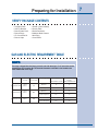
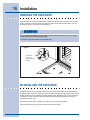
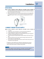
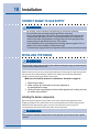
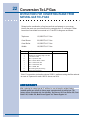
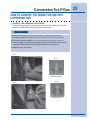
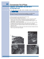
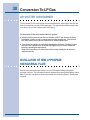
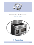
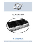
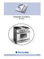
E30GF74GPS E36GF75GPS E36GF76GPS
318201761
2 Finding Information
READ AND SAVE THESE INSTRUCTIONS
NO
TE
NOTE
Installer: Leave instructions with owner. Owner: Read your range Use & Care guide. It
contains important safety information for operating this appliance. It also has many
suggestions for getting the best results from your appliance.
Read all instructions before installing the range.
For your safety, please read and observe all safety instructions. This
guide will help you anticipate all installations connections.
QUESTIONS
For toll-free telephone support in the U.S. and Canada:
1-877- 4ELECTROLUX (1-877-435-3287)
For online support and Internet product information:
www.electroluxusa.com
©2007 Electrolux Home Products, Inc.
Post Office Box 212378, Augusta, Georgia 30917, US
All rights reserved. Printed in the USA
Finding Information
TABLE OF CONTENTS
Please Read And Save This Guide .................... 2
Questions .......................................................... 2
Table Of Contents ............................................. 3
Safety ..................................................................... 4
Important Safety Instructions ............................... 4
Definitions ........................................................... 4
Safety Precautions ........................................... 5
Preparing for Installation ................................... 7
Verifying Package Contents ................................ 7
Gas/Electric Requirement Table............................... 7
Electrical Power Supply Requirements .................. 8
Gas/Electric Connection Rough-In ..................... 9
Cabinet/Countertop Preparation .......................... 10
General Dimensions ........................................ 11
Wood/Composite Overlay Installation...................... 13
Installing Anti-Tip Bracket ...................................... 14
Installing the 36” Range Optional Backguard......... 15
Removing Oven Door.......................................... 16
Re-Installing Oven Door.................................. 16
Grounding..................................................... 17
Connect Range To Gas Supply.........................17
Installing Range...............................................18
Verifying the Operation ...................................... 19
To Insure Proper and Safe Operation..................... 20
Converting from Natural Gas To LP Gas................. 21
3
4 Safety
IMPORTANT SAFETY INSTRUCTIONS
Safety
SAFETY PRECAUTIONS
5
6 Safety
WARNING
Never use this appliance as a space heater to heat or warm a room. Doing so may result in carbon
monoxide poisoning and overheating of the oven.
Preparing for Installation
VERIFY PACKAGE CONTENTS
• Literature Pack
• Anti-Tip Bracket
• Burner Grate Pack
• Burner Rings
• LP Conversion Kit
• Burner Caps
• Griddle (some models)
• Simmer Plate
• Broiler Pan/Insert
• Stainless Steel Cleaner
• Wok Ring
• Oven Racks
GAS AND ELECTRIC REQUIREMENT TABLE
NO
TE
NOTE
This range is shipped from the factory pre-set for use with natural gas. For LP conversion see the
accompanying LP Conversion Kit. The electrical information in the table is also located on the
serial number label on the range.
Model No.
E30GF74GPS
E36GF75GPS
E36GF76GPS
Electrical
Circuit
Total
Connected
120 V,
60Hz,
5A
120 V,
60Hz,
120 V,
60Hz,
8A
5A
Gas Type
Manifold Pressure
Minimum Gas
Supply
Water Column Inches Water Column Inches
Natural
5"
6"
Liquid Propane
10"
11"
Natural
5"
6"
Liquid Propane
10"
11"
Natural
5"
6"
Liquid Propane
10"
11"
7
8 Preparing for Installation
ELECTRICAL POWER SUPPLY REQUIREMENTS
It is the owner’s responsibility to ensure that the electrical connection
of this appliance is performed by a qualified electrician. The electrical
installation, including minimum supply wire size and grounding, must be
in accordance with the National Electric Code ANSI/NFPA 70-1993*
(or latest revision) and local codes and ordinances. In Canada,
electrical grounding must be in accordance with the current CSA C22.1
Canadian Electrical Code Part 1 and/or local codes.
*A copy of the standard must be obtained from:
National Fire Protection Association
1 Batterymarch Park
Quincy, Massachusetts 02269-9101
The correct voltage, frequency, and amperage must be supplied to the
appliance from a separate, grounded, circuit that is protected by a
properly sized circuit breaker or time delay fuse.
WARNING
If the gas or electric service provided does not meet the product specifications, do not
proceed with the installation. Call the selling dealer, the gas supplier, or a licensed
electrician.
NO
TES
NOTES
The power supply must be properly grounded. Improper grounding will result in
continuous sparking of the electrodes, even after flame ignition.
If there is any doubt as to whether the power supply is properly polarized or grounded,
have it checked by a qualified electrician.
Use 120V, 60Hz, and properly grounded branch circuit protected by a 15-amp or 20-amp
circuit breaker or time delay fuse.
Preparing for Installation
GAS AND ELECTRICAL ROUGH-IN
Locations
A manual shut valve must be installed in the gas piping, external to the
appliance, for the purpose of turning on or shutting off gas to the
appliance. Place the location of the range and the gas supply to allow
access to the valve when the unit is installed. Access to the remote
circuit breaker panel/fuse box, with the range in place, must also be
allowed for in the installation. Any openings in the wall behind the
appliance and in the floor under the appliance must be sealed. Both the
gas supply piping and shut-off valve, and the electrical junction box/
receptacle must be located so they do not interfere with the range when
it is installed. In addition, the junction box must be located so the range
can be removed for service when the conduit supplied with the unit is
attached to the junction box. Do not lengthen the conduit or wiring
provided with the range.
NO
TES
NOTES
The areas shown in the illustrations, denote the location of the gas stub and the
electrical junction box/receptacle. These are suggested locations. For replacement
purposes, the location of the existing utilities may be utilized provided that they do not
interfere with the sides or rear of the range. If installing the gas valve behind the range,
verify that local building codes will permit this.
Figure 1
Center Line
9
10 Preparing for Installation
CABINET AND COUNTERTOP PREPARATION
Check your local building codes for the proper method of installation. In the
absence of local codes, this appliance should be installed in accordance with the
National Fuel Gas Code ANSI Z223.1/NFPA 54. In Canada, installation must
conform to current Natural Gas Installation Code, CAN1-1.1-M and the local codes
where applicable. This range has been design-certified according to ANSI Z21.1b,
latest edition. Be certain that the appliance being installed is correct for the gas
service being provided. Refer to the rating label located on the kick panel and/or the
table on page 7 for gas supply requirements.
All dimensions shown are based on standard American cabinets, 36 inches
(914mm) high at the finished countertop by 24 inches (610mm) deep, with a 25
inch (635mm) overall countertop depth. When installing the range into nonstandard
cabinets, minimum clearances shown in the diagrams on page 11 must be
maintained.
Carefully check the location where the range is to be installed. For best
performance, the range should be placed away from drafts that may be caused by
doors, windows and HVAC outlets.
NO
TES
NOTES
•
•
•
•
•
If cabinet storage space is to be provided directly above the range, the risk of
personal injury may be reduced by installing a ventilating hood that projects
horizontally a minimum of 5 inches beyond the face of the cabinets.
The range may be installed flush to the rear wall. We recommend installing a
noncombustible material on the rear wall above the range and up to the vent
hood. It is not necessary to install noncombustible materials behind the range
below the countertop height.
The minimum distance from the sides of the range above the countertop to
combustible side walls must be at least 10 inches..
All models are delivered with a 3.5” backguard from the factory. A 9” backguard
is available on the E36GF75GPS AND E36GF76GPS as options.
Utilities may be located: In the lower left corner of the adjacent right cabinet.
(Refer to Figure 2)
I M P O R TA N T
•
Contact your local building department to verify compliance with local code
interpretation.
Preparing for installation
GENERAL DIMENSIONS
Plan the installation so that the electrical connection, gas shut-off valve, and pressure
regulator are accessible from the front of the cabinet.
Figure 2
Ventilation
Hood
13"
(330 mm)
Max
Top of
Finished
Counter
Vertical noncombustible
surface
30" (762 mm) Min
10" (254 mm) Min.
to combustible sides walls
above the range (both sides)
18" (457 mm)
Min
25"
(635 mm)
Recommended utility location
E30GF74GPS, E36GF75GPS,
E36GF76GPS
Cutout Dimensions
Model
“A”
“B”
E30GF74 Series
30” (762 mm)
Minimum Recommended
30 1/16” (764 mm)
E36GF75 Series
36” (914 mm)
Minimum Recommended
36 1/16” (916 mm)
E36GF76 Series
36” (914 mm)
Minimum Recommended
36 1/16” (916 mm)
11
12 Preparing for Installation
GENERAL DIMENSIONS
Preparing for Installation
WOOD/COMPOSITE OVERLAY INSTALLATION
The bottom of an overhead hood should be 30” minimum to 36” above the
countertop. This would typically result in the bottom of the hood being 66” to 72”
above the floor. These dimensions provide safe an efficient operation of the hood.
13
14 Installation
INSTALLING THE ANTI-TIP BRACKET
**
**Note: Increase or decrease this
dimension as
necessary for range top to be flush with countertop.
FIG. 3
Installation
INSTALLING THE 36” RANGE OPTIONAL
BACKGUARD
Your Electrolux IconMR range was shipped with a backguard in place. These instructions
cover the installation of one of the optional backguards.
Installing the Range Optional Backguard:
WARNING
Be sure the range is not connected to gas or power before proceeding.
1. Remove existing backguard by removing 4 screws on rear of backguard (2 screws
per side).
2. Remove the backguard from its box.
3. To avoid scratches, place small scraps of thin cardboard on the rear of the side
panels where the backguard will make contact. With the assistance of at least
one other person, carefully lift the backguard and place down on to the range top.
Special attention should be given to the lower flange in front of the backguard,
which must be fit between the stainless steel side panels.
4. Fasten the screws through the rear flange in the same location in which they were
removed from factory supplied backguard.
5. Connect the gas line to the regulator. Reposition and attach the access panel or
the back cover if the entire back cover was removed.
6. You are now ready to continue with the range installation.
Figure 3
Backguard
Backguard Installation
(36" range shown)
15
16 Installation
REMOVING THE OVEN DOOR
Open the door to its fully opened position. Rotate the catch over the retaining arm on each
hinge. Lift the oven door to about a 30 degree angle from the horizontal position. Pull the
door away from the oven while continuing to lift.
WARNING
Do not attempt to disengage the hinge catches with the door removed from the oven. The hinge
springs could release causing personal injury.
Do not lift or carry the oven door by the handle door.
Figure 4
To remove
oven door,
rotate catch as
shown.
RE-INSTALLING THE OVEN DOOR
Grasp the oven door on opposite sides and lift it until the door hinges are aligned with the
openings in the oven frame. Holding the door at about a 30 degree angle from the horizontal,
slide the hinges into the openings until the bottom hinge arms drop fully into the two hinge
receptacles. Lower the door to the fully opened position, and then rotate the two hinge
catches toward the oven.
Open and close the door completely to ensure that it is properly installed.
Peel off the protective layer of plastic that covers the door panel.
Installation
GROUNDING
1
The range is equipped with a three-prong power cord (grounding plug which mates
with a standard three-prong grounding wall receptacle to minimize the possibility of
electrical shock hazard from the range).
Where a standard two-prong wall receptacle is encountered, it is the responsibility
and obligation of the customer to have it replaced with a properly grounded threeprong wall receptacle. Do not cut or remove the grounding prong from the power
cord.
2
CONNECT RANGE TO GAS SUPPLY
1
2
3
4
5
6
7
Turn off gas.
Install a male 1/2” flare union adapter to 1/2” NPT internal thread of regulator inlet.
Connect flexible gas line connector to end union and regulator inlet.
Install the male flare union adapter on the manual shut-off valve, taking care to support the
shut-off valve . Do not allow the valve to move or turn.
Position the range into the cabinet to allow connection of flexible connector at the shut-off
valve.
When all connections have been made, make sure all range controls are in the “OFF”
position and turn on main gas supply valve.
Use a leak detector at all joints and connections to check for leaks in the system. Do not
use a flame to check for gas leaks.
The appliance must be isolated from the building’s gas supply piping system by closing
it’s individual manual shut-off valve during any pressure testing of the gas supply piping
system at test pressures equal to or less than 1/2 psig (3.5kPa).
NO
TE
NOTE
The gas pressure regulator is preset at the factory for natural gas to use with the appliance. To
convert the range to LP gas, see instructions supplied in the LP conversion package.
17
18 Installation
CONNECT RANGE TO GAS SUPPLY
WARNING
•
•
•
•
•
Do not apply excessive pressure when tightening gas connections and fittings.
Do not use teflon tape or plumber’s putty on gas flex line connections.
Turn all control valves to the “OFF” position. Turn on gas supply and check all lines and
connections with leak detector, such as soap and water solution. Do not use flame to
check for leaks. After verifying that there are no gas leaks, turn off the gas supply to the
range by turning the gas shut-off valve to the “OFF” position.
For LP installations, the LP gas tank must have its own high pressure regulator. This is in
addition to the pressure regulator provided with the range.
The maximum gas supply pressure to the regulator must never exceed 1/2 pound per square
INSTALLING THE RANGE
WARNING
The 30” and 36” ranges require an Anti-Tip device. Before installing the range, you must locate and
secure the Anti-Tip bracket to the floor.
Measure from the floor to the countertop and adjust the leveling legs as required to position
the top frame at the desired height, based on the cabinet and countertop installation.
Carefully slide the range into position in the cutout.
Make sure the anti-tip bracket is installed as directed on page 14.
1. Slide range forward.
2. Make sure the anti-tip bracket is securely attached to
the wall behind the range.
3. Safely slide the range slightly and move back against wall, making sure the
pin slides under bracket.
Installing the burner components
Remove the burner bases, burner heads, burner caps, and porcelain grates from their
shipping packages. Place each burner onto its corresponding burner base, being certain
that the burners align with the ignitor correctly. Set each burner cap on top of its
corresponding burner head. Place each grate onto the top frame.
WARNING
Never attempt to operate the cooktop section of the range with any of the burner caps or grates
removed.
Operation
VERIFYING THE OPERATION
Before beginning the test procedure, ensure that all cooktop control valves are in
the “OFF” position, and all burner rings, burner caps, and grates are properly
positioned on the top frame. Turn on the gas supply at the shut-off valve.
Turn on the power supply to the range. Select a temperature of 350°F by rotating
the oven selector knob to “350”. Rotate knob to the “Off” position to stop the
heating process.
Test each top burner separately by pressing and turning one control knob at a time
counterclockwise to the “HIGH” position. All ignitors will spark continuously, but
only the burner with gas flowing to it will ignite. (It will take approximately 4 seconds
for ignition to occur, at which time the ignitors will stop sparking. If ignition does not
occur within 4 seconds, turn off the knob, wait for at least 2 minutes to allow any
gas to dissipate, then repeat this ignition test.) The control knob can then be
rotated counterclockwise from “HIGH” to “LOW” to adjust the flame height
progressively.
Repeat the ignition test for all burners. When installed properly, the flame will be
steady and quiet. It will also have a sharp, blue inner cone that will vary in length
proportional to the burner size.
WARNING
•
The range and shut-off valve must be disconnected from the gas supply piping during any
pressure testing exceeding 1/2 psi (3.5kPa).
•
The range must be isolated from the gas supply piping by closing the shut-off valve during
any pressure testing at or below 1/2 psi (3.5kPa).
NO
TES
NOTES
If either the oven or cooktop does not operate properly follow these troubleshooting steps:
•
Verify the power and the gas are supplied to the range.
•
Check the electrical connections and gas supply to ensure the installation has been
completed correctly.
•
If the appliance still does not work, contact an authorized service company. Do not attempt
to repair the appliance yourself. Electrolux is not responsible for service required to correct
faulty installation.
19
20 Operation
TO ENSURE PROPER AND SAFE OPERATION
NO
TE
NOTE
REFER TO THE USE AND CARE MANUAL FOR DETAILED INSTRUCTIONS.
•
•
•
•
•
•
•
•
•
•
•
•
•
•
•
•
•
•
•
Read all instructions before using this appliance. Install or locate the appliance only in
accordance with the provided Installation Instructions.
Do not attempt to adjust, repair, service, or replace any part of your appliance unless it
is specifically recommended in this guide.
Do not leave children alone or unattended in the area where the range is in use. Never
allow children to sit or stand on any part of the oven. Do not let children play with the
range.
All other servicing should be referred to a qualified service agency.
Have the technician show you the location of the gas shut off valve and how to shut it off
in an emergency situation.
Always disconnect power to appliance before any type of servicing.
Do not use abrasive or caustic cleaners or detergents on this appliance. They may
cause permanent damage to the surface.
When cooking, set the burner controls so that the flame heats only the bottom of the
utensil and does not overlap at the sides of the utensil.
Utensils (pots & pans) that conduct heat slowly, i.e. glass pots, should be used in
conjunction with burner flames at a low or medium setting.
Turn off all controls and wait for appliance parts to cool before touching or cleaning
them.
Do not touch the burner grates or surrounding areas until they are cool.
Do not use water on grease fires.
Clean appliance with caution.
Always turn pot handles to the side or back of the range. Do not turn handles towards
the area where they are easily burned. Handles should not extend over adjacent
burners.
Use range only for cooking tasks expected of a home appliance as outlined in this
manual.
When using the cooktop, do not touch the grates, burner caps, burner bases, or any
other parts in proximity to the flame. These components may be hot enough to cause
burns.
Use dry potholders. Moist or damp potholders on hot surfaces may result in burns from
steam. Do not let potholders touch hot surface areas. Do not use a towel or other bulky
cloth.
Do not heat unopened food containers. Build up of pressure may cause the container to
explode and result in injury.
During and after use, so not touch interior surfaces of the oven until cool.
NO
TE
NOTE
Prior to operating the cooktop or oven sections of the range, please read the accompanying Use
and Care Manual carefully. Important safety, service and warranty information is contained within
this manual.
Conversion To LP Gas
INSTRUCTIONS FOR CONVERTING RANGE
OPERATION TO OPERATE ON LP GAS
INSTALLATION AND SERVICES MUST BE PERFORMED BY
A QUALIFIED INSTALLER.
IMPORTANT: SAVE FOR THE LOCAL ELECTRICAL INSPECTOR’S USE.
READ AND SAVE THESE INSTRUCTIONS FOR FUTURE REFERENCE.
WARNING
This conversion kit must be installed by a qualified service technician in accordance
with the manufacturer’s instructions and all applicable codes and requirements of the
authority having jurisdiction. Failure to follow instructions may result in fire, explosion
or production of carbon monoxide causing property damage, personal injury or loss of
life. The qualified service agency is responsible for the proper installation of this kit.
The installation is not proper and complete until the operation of the converted
appliance is checked as specified in the manufacturer’s instructions supplied with this
kit.
CA
UTION
AUTION
Before proceeding with the conversion, shut off the gas supply before disconnecting
electrical power to the range. Be sure power supplies are off before installing the
conversion kit. Failure to do so could cause serious bodily injury.
TOOLS REQUIRED FOR L.P. CONVERSION:
3/8” AND 5/8” OPEN END WRENCH
1/8” WIDE FLAT BLADE SCREWDRIVER
PHILLIPS SCREWDRIVER
9/32 NUT DRIVER
5/32 NUT DRIVER
7mm NUT DRIVER
21
22 Conversion To LP Gas
INSTRUCTIONS FOR CONVERTING RANGE FROM
NATURAL GAS TO LP GAS
Determine the combination of top burners that are featured on your range.
Identify the parts you need from this kit to complete the L.P. conversion. When
burners are converted from natural to L.P. the BTU ratings are as follows:
Top burner
15,000 BTU L.P. Gas
Oven Burner
22,000 BTU L.P. Gas
Oven Broiler
16,500 BTU L.P. Gas
Griddle
18,500 BTU L.P. Gas
Quantity
1
Part Description
Notes
LP Conversion kit label
1
Instruction for converting range to LP Gas
1
LP Conversion Label
6
Orifice - Top Burner, #58
6
Orifice - Simmer Burner, .46mm
1
Orifice - Oven Burner, #55
1
Orifice - Oven Broiler, #56
1
Orifice - Griddle, #55
6
Main burner bypass jet, blue ring
6
Simmer burner bypass jet
*Note: For operation at elevations above 2000 ft., appliance rating shall be reduced
at a rate of 4 percent for each 1000 ft. above sea level
I M P O R TA N T
After replacing the natural gas to LP orifices, be sure to keep the original factory
installed natural gas orifices for future range conversion back to natural gas. The
factory orifices are marked with the following: Top Burners 165; Oven Burner 226; Oven
Broiler 185; Griddle 206; Main Burner Bypass Jet; Simmer Bypass Jet
Conversion To LP Gas
HOW TO CONVERT THE RANGE FOR USE WITH
LP/PROPANE GAS
1. CONVERT THE PRESSURE REGULATOR
To access the gas regulator, pull the range away from the cabinet wall. The gas
regulator is located at the bottom right corner of the range.
WARNING
a. Electrical shock hazard can occur and result in injury or death. Disconnect electrical
power to the range before servicing. Do not remove regulator or allow it to turn during servicing.
b. Unscrew the cap from the regulator. Do not remove the spring from the regulator (see Figure 1)..
c. Unscrew the plastic insert from the cap (see Figure 2 and 3). Turn the insert around so that the
longer stem is facing toward the cap (see Figure 4). Screw the insert into the cap.
d. Replace the cap on the regulator.
Figure 1
Figure 3
Position for NG
Figure 2
Figure 4
Position for LP
23
24 Conversion To LP Gas
CONVERT TOP BURNER FOR USE WITH
LP/PROPANE GAS
CA
UTION
CAUTION
Save the natural gas orifices removed from the appliance for possible future
conversions to natural gas. Take extra care when handling steel parts.
a. Remove top grates, burner caps and inner burner rings.
b. Lift off outer burner heads and burner bases.
c. Remove the factory installed natural gas orifices from the center of the orifice
holders using a 7mm nut driver. Remember to keep the original natural
gas orifices for future conversions back to natural gas. Refer to page 22 under
“IMPORTANT” to identify their markings.
d. Using a 9/32” nut driver, replace the main orifice in each orifice holder with orifice
size (#58). Tighten each orifice until snug. Use caution not to over tighten.
e. Using a 5/32” nut driver, replace the Simmer orifice in each orifice holder with the
orifice size (0.46).
f. Replace the outer burner heads back to the main burner bases. Replace the inner
burner rings, burner caps and grates.
b.
a.
c.
e.
Conversion To LP Gas
CONVERT OVEN BURNER ORIFICE TO LP/PROPANE
GAS
a. Remove the toe kick panel.
b. Remove the two (2) screws on the bottom of the toe kick panel. Hold the bottom
edge of toe kick panel at the middle section and slightly lift towards the front. Hold
the toe kick panel on both ends and slowly pull away towards the front.
c. Remove the (2) screws holding the orifice bracket and locate the orifice. Remove
orifice using a adjustable wrench. Replace with oven burner orifice size (#55). Do
not over tighten. Replace the orifice bracket, aligning the new orifices into the air
shutter of the oven burner.
a.
c.
b.
25
26 Conversion To LP Gas
CONVERT BROIL BURNER ORIFICE FOR LP/
PROPANE GAS (16.500 BTU)
a. Remove back cover (See Fig. a)
b. Using an adjustable wrench, remove the orifice from the orifice holder. Replace with
oven broiler orifice size (#55).
a.
b.
Conversion To LP Gas
CONVERT GRIDDLE ORIFICE FOR LP/PROPANE GAS
(18,500 BTU)
(FOR 36” RANGES EQUIPPED WITH 4 TOP BURNERS AND A GRIDDLE)
a. Remove back cover (See “Fig. a” on previous page)
b. Carefully remove the griddle plate using caution as the plate is very heavy.
As the plate’s lifted, make sure to remove the thermostat located beneath the
plate.
c. Using an adjustable wrench, remove the orifice from the orifice holder. Replace
with griddle orifice size (#56).
b.
c.
27
28 Conversion To LP Gas
CONVERT GAS VALVES FOR LP/PROPANE GAS
a. Remove control knobs, bezel and control panel.
b. Using a flat screwdriver, replace main burner bypass jets with bypass jets for LP
and simmer bypass jets with bypass jets for LP. Save the main bypass jets (blue
for NG) in the plastic bag labeled main jets and simmer bypass
(blue for NG) jets in the bag for the simmer jets.
a.
b.
Conversion To LP Gas
RECONNECT GAS AND ELECTRICAL SUPPLY TO
RANGE
Leak testing of the appliance shall be conducted according to the installation
instructions provided with the range.
Checking for Manifold Gas Pressure
If it is necessary to check the manifold gas pressure, remove the burner cap, inner
ring, outer burner head and burner base of the right front top burner and connect a
manometer (water gauge) or other pressure test device to the burner orifice. Use a
rubber hose, and hold the end of the tube tight over the orifice. Turn the gas valve
on. For a more accurate pressure check, have at least two (2) other top burners
burning. Be sure that the gas supply (inlet) pressure is at least one inch above the
specified range manifold pressure. The gas supply pressure should never be over
14” water column. When properly adjusted, the manifold water column pressure is
10” for LP/Propane gas or 5” for Natural Gas.
CA
UTION
AUTION
Do not use a flame to check for gas leaks
a. Disconnect the range and its individual shut-off valve from the gas supply piping
system during any pressure of that system at test pressures greater than 14” of
water column pressure.
b. The appliance must be isolated from the gas supply piping system by closing its
individual manual shut-off valve during any pressure testing of the supply system
at test pressure equal to or less than 14” water column pressure.
29
30 Conversion To LP Gas
AIR SHUTTER OVEN BURNER
The air shutter for the oven burner may need adjustment, especially if the unit has
been converted for use with LP/Propane gas. The approximate flame length of the
oven burner is one inch (distinct inner blue flame).
To Determine if the oven burner flame is proper:
a. With the toe kick removed, set the oven to bake at 350°F and observe the flame.
If the flame is yellow in color, increase the air shutter opening size. If the flame is
blue lifting away from the burner, reduce the air shutter opening size.
b. Turn off oven and allow it to cool before adjusting the air shutter. To adjust, loosen
the lock screw, reposition the air shutter and tighten the lock screw. Retest the
burner by repeating the steps above.
When the burner flame is a distinct blue color burning steadily, the air shutter is
adjusted correctly.
INSTALLATION OF NEW LP/PROPANE
RATING/SERIAL PLATE
Record the model and serial number on the LP/Propane Rating Serial plate
provided in this kit. The information can be obtained from the existing Rating / serial
plate. Place the new plate as close as possible to the existing Rating / Serial plate
on range.