1
AcerPower 2000/Aspire L310
Service Guide
Service guide files and updates are available
on the AIPG/CSD web; for more information,
please refer to http://csd.acer.com.tw
PRINTED IN TAIWAN
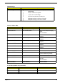
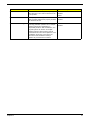
Revision History
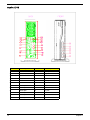
Please refer to the table below for the updates made on AcerPower 2000/Aspire L310 service guide.
Date
II
Chapter
Updates
Copyright
Copyright © 2006 by Acer Incorporated. All rights reserved. No part of this publication may be reproduced,
transmitted, transcribed, stored in a retrieval system, or translated into any language or computer language, in
any form or by any means, electronic, mechanical, magnetic, optical, chemical, manual or otherwise, without
the prior written permission of Acer Incorporated.
III
Disclaimer
The information in this guide is subject to change without notice.
Acer Incorporated makes no representations or warranties, either expressed or implied, with respect to the
contents hereof and specifically disclaims any warranties of merchantability or fitness for any particular
purpose. Any Acer Incorporated software described in this manual is sold or licensed "as is". Should the
programs prove defective following their purchase, the buyer (and not Acer Incorporated, its distributor, or its
dealer) assumes the entire cost of all necessary servicing, repair, and any incidental or consequential
damages resulting from any defect in the software.
Acer is a registered trademark of Acer Corporation.
Intel is a registered trademark of Intel Corporation.
Other brand and product names are trademarks and/or registered trademarks of their respective holders.
IV
Conventions
The following conventions are used in this manual:
Screen messages
Denotes actual messages that appear
on screen.
NOTE
Gives bits and pieces of additional
information related to the current
topic.
WARNING
Alerts you to any damage that might
result from doing or not doing specific
actions.
CAUTION
Gives precautionary measures to
avoid possible hardware or software
problems.
IMPORTANT
Reminds you to do specific actions
relevant to the accomplishment of
procedures.
V
Preface
Before using this information and the product it supports, please read the following general information.
VI
1.
This Service Guide provides you with all technical information relating to the BASIC CONFIGURATION
decided for Acer's "global" product offering. To better fit local market requirements and enhance product
competitiveness, your regional office MAY have decided to extend the functionality of a machine (e.g.
add-on card, modem, or extra memory capability). These LOCALIZED FEATURES will NOT be covered
in this generic service guide. In such cases, please contact your regional offices or the responsible
personnel/channel to provide you with further technical details.
2.
Please note WHEN ORDERING FRU PARTS, that you should check the most up-to-date information
available on your regional web or channel. If, for whatever reason, a part number change is made, it will
not be noted in the printed Service Guide. For ACER-AUTHORIZED SERVICE PROVIDERS, your Acer
office may have a DIFFERENT part number code to those given in the FRU list of this printed Service
Guide. You MUST use the list provided by your regional Acer office to order FRU parts for repair and
service of customer machines.
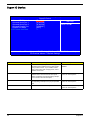
Table of Contents
Chapter 1
System Specifications
1
Overview . . . . . . . . . . . . . . . . . . . . . . . . . . . . . . . . . . . . . . . . . . . . . . . . . . . . . . . . . . . .1
Features . . . . . . . . . . . . . . . . . . . . . . . . . . . . . . . . . . . . . . . . . . . . . . . . . . . . . . . . . . . .2
System Block Diagram . . . . . . . . . . . . . . . . . . . . . . . . . . . . . . . . . . . . . . . . . . . . . . . . 6
Main Board Layout . . . . . . . . . . . . . . . . . . . . . . . . . . . . . . . . . . . . . . . . . . . . . . . . . . . .7
Your Acer Desktop tour . . . . . . . . . . . . . . . . . . . . . . . . . . . . . . . . . . . . . . . . . . . . . . . .9
Front and back panel . . . . . . . . . . . . . . . . . . . . . . . . . . . . . . . . . . . . . . . . . . . . . .9
System Peripherals . . . . . . . . . . . . . . . . . . . . . . . . . . . . . . . . . . . . . . . . . . . . . . . . . . .11
Mouse (PS/2 or USB, manufacturing option) . . . . . . . . . . . . . . . . . . . . . . . . . . .11
Keyboard (PS/2 or USB, manufacturing option) . . . . . . . . . . . . . . . . . . . . . . . . .11
Speakers . . . . . . . . . . . . . . . . . . . . . . . . . . . . . . . . . . . . . . . . . . . . . . . . . . . . . . .11
Acer Empowering Technology . . . . . . . . . . . . . . . . . . . . . . . . . . . . . . . . . . . . . . . . . .13
Empowering Technology password . . . . . . . . . . . . . . . . . . . . . . . . . . . . . . . . . .13
Acer eSettings Management . . . . . . . . . . . . . . . . . . . . . . . . . . . . . . . . . . . . . . .13
Acer eLock Management . . . . . . . . . . . . . . . . . . . . . . . . . . . . . . . . . . . . . . . . . .14
Acer eDataSecurity Management . . . . . . . . . . . . . . . . . . . . . . . . . . . . . . . . . . .15
Acer ePerformance Management . . . . . . . . . . . . . . . . . . . . . . . . . . . . . . . . . . .17
Acer eAcoustics Management . . . . . . . . . . . . . . . . . . . . . . . . . . . . . . . . . . . . . .17
Acer eRecovery Management . . . . . . . . . . . . . . . . . . . . . . . . . . . . . . . . . . . . . .18
Hardware Specifications and Configurations . . . . . . . . . . . . . . . . . . . . . . . . . . . . . . .20
Power Management Function ( ACPI support function) . . . . . . . . . . . . . . . . . . . . . . .26
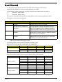
Dual Channel . . . . . . . . . . . . . . . . . . . . . . . . . . . . . . . . . . . . . . . . . . . . . . . . . . . . . . .27
Chapter 2
System Utilities
29
Entering Setup . . . . . . . . . . . . . . . . . . . . . . . . . . . . . . . . . . . . . . . . . . . . . . . . . . . . . .30
Product Informatoin . . . . . . . . . . . . . . . . . . . . . . . . . . . . . . . . . . . . . . . . . . . . . . . . . .31
Standard CMOS Features . . . . . . . . . . . . . . . . . . . . . . . . . . . . . . . . . . . . . . . . . . . . .32
Advanced BIOS Features . . . . . . . . . . . . . . . . . . . . . . . . . . . . . . . . . . . . . . . . . . . . . .35
CPU Feature . . . . . . . . . . . . . . . . . . . . . . . . . . . . . . . . . . . . . . . . . . . . . . . . . . . .36
Advanced Chipset Features . . . . . . . . . . . . . . . . . . . . . . . . . . . . . . . . . . . . . . . . . . . .38
Integrated Peripherals . . . . . . . . . . . . . . . . . . . . . . . . . . . . . . . . . . . . . . . . . . . . . . . .40
OnChip IDE Device . . . . . . . . . . . . . . . . . . . . . . . . . . . . . . . . . . . . . . . . . . . . . . .42
Onboard Device . . . . . . . . . . . . . . . . . . . . . . . . . . . . . . . . . . . . . . . . . . . . . . . . .44
Super IO Device . . . . . . . . . . . . . . . . . . . . . . . . . . . . . . . . . . . . . . . . . . . . . . . . .46
Power Management Setup . . . . . . . . . . . . . . . . . . . . . . . . . . . . . . . . . . . . . . . . . . . . .47
PnP/PCI Configuration . . . . . . . . . . . . . . . . . . . . . . . . . . . . . . . . . . . . . . . . . . . . . . . .49
PC Health Status . . . . . . . . . . . . . . . . . . . . . . . . . . . . . . . . . . . . . . . . . . . . . . . . . . . .50
Frequency Control . . . . . . . . . . . . . . . . . . . . . . . . . . . . . . . . . . . . . . . . . . . . . . . . . . .51
Load Default Settings . . . . . . . . . . . . . . . . . . . . . . . . . . . . . . . . . . . . . . . . . . . . . . . . .52
Set Supervisor/User Password . . . . . . . . . . . . . . . . . . . . . . . . . . . . . . . . . . . . . . . . . .53
Save & Exit Setup . . . . . . . . . . . . . . . . . . . . . . . . . . . . . . . . . . . . . . . . . . . . . . . . . . . .54
Exit Without Saving . . . . . . . . . . . . . . . . . . . . . . . . . . . . . . . . . . . . . . . . . . . . . . . . . . .55
Chapter 3
Machine Disassembly and Replacement
57
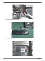
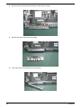
General Information . . . . . . . . . . . . . . . . . . . . . . . . . . . . . . . . . . . . . . . . . . . . . . . . . .58
Before You Begin . . . . . . . . . . . . . . . . . . . . . . . . . . . . . . . . . . . . . . . . . . . . . . . .58
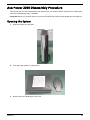
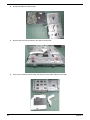
AcerPower 2000 Disassembly Procedure . . . . . . . . . . . . . . . . . . . . . . . . . . . . . . . . .59
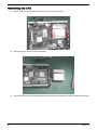
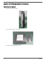
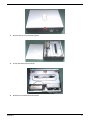
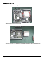
Opening the System . . . . . . . . . . . . . . . . . . . . . . . . . . . . . . . . . . . . . . . . . . . . . .59
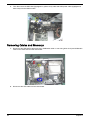
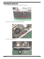
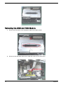
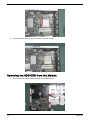
Removing the ODD and HDD Module . . . . . . . . . . . . . . . . . . . . . . . . . . . . . . . .61
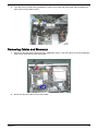
Removing Cables and Memorys . . . . . . . . . . . . . . . . . . . . . . . . . . . . . . . . . . . . .62
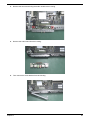
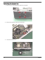
Removing the CPU . . . . . . . . . . . . . . . . . . . . . . . . . . . . . . . . . . . . . . . . . . . . . . .64
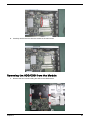
Removing the HDD/ODD from the Module . . . . . . . . . . . . . . . . . . . . . . . . . . . . .65
VII
Table of Contents
Removing the System Fan . . . . . . . . . . . . . . . . . . . . . . . . . . . . . . . . . . . . . . . . .67
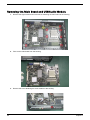
Removing the Main Board and USB/Audio Module . . . . . . . . . . . . . . . . . . . . . .68
Aspire L310 Disassembly Procedure . . . . . . . . . . . . . . . . . . . . . . . . . . . . . . . . . . . . .70
Opening the System . . . . . . . . . . . . . . . . . . . . . . . . . . . . . . . . . . . . . . . . . . . . . .70
Removing the ODD and HDD Module . . . . . . . . . . . . . . . . . . . . . . . . . . . . . . . .72
Removing Cables and Memorys . . . . . . . . . . . . . . . . . . . . . . . . . . . . . . . . . . . . .73
Removing the CPU . . . . . . . . . . . . . . . . . . . . . . . . . . . . . . . . . . . . . . . . . . . . . . .75
Removing the HDD/ODD from the Module . . . . . . . . . . . . . . . . . . . . . . . . . . . . .76
Removing the System Fan . . . . . . . . . . . . . . . . . . . . . . . . . . . . . . . . . . . . . . . . .78
Removing the Main Board and USB/Audio Module . . . . . . . . . . . . . . . . . . . . . .79
Chapter 4
Troubleshooting
81
Power-On Self-Test (POST) . . . . . . . . . . . . . . . . . . . . . . . . . . . . . . . . . . . . . . . . . . . .82
POST Error Messages List . . . . . . . . . . . . . . . . . . . . . . . . . . . . . . . . . . . . . . . . . . . . .88
Error Symptoms List . . . . . . . . . . . . . . . . . . . . . . . . . . . . . . . . . . . . . . . . . . . . . . . . . .90
Undetermined Problems . . . . . . . . . . . . . . . . . . . . . . . . . . . . . . . . . . . . . . . . . . . . . . .95
Main Board Layout . . . . . . . . . . . . . . . . . . . . . . . . . . . . . . . . . . . . . . . . . . . . . . . . . . .97
Chapter 5
Jumper and Connector Information
97
Chapter 6
FRU (Field Replaceable Unit) List
99
AcerPower 2000/Aspire L310 Exploded Diagram . . . . . . . . . . . . . . . . . . . . . . . . . .100
Parts . . . . . . . . . . . . . . . . . . . . . . . . . . . . . . . . . . . . . . . . . . . . . . . . . . . . . . . . . . . . .101
VIII
Chapter 1
System Specifications
Overview
The AcerPower 2000 leverages Acer's ultra-compact design, giving the system the versatility to be deployed in
almost any workspace. At only 3 liters in volume and with noise-output performance of just 26 dB, the system
will be especially appealing when space is at a premium; where distractions such as noise need to be avoided;
or simply when a user wishes to create a more stylish, less cluttered workspace.
The system is ideally suited for the office, boasting the Intel® Core™2 Duo processor, Intel® Graphics Media
Accelerator (GMA) 3000 graphics, up to 400 GB hard disk, and dual-channel DDR2 memory. These features
ensure excellent productivity and multitasking performance. The system's easy-to-manage form factor saves
desk space, reduces noise, and lowers costs, creating a more comfortable and productive office environment.
The Aspire L310 delivers energy-efficient performance and whisper-quiet operation in a space-saving form
factor that's up to 10 times smaller than a traditional PC tower. Only slightly larger than a hardback book,
Acer's new ultra-compact chassis packs all of the features home-users need to accomplish their everyday
tasks with efficiency and ease.
From getting online, to creating important professional documents, to enjoying a full digital-entertainment
experience with TV, DVD movies and theater-quality surround sound, the Aspire L310 has the performance to
do it all — just like a big tower PC. Max versatility, mini size, the Aspire L310 is a groundbreaking product for
the home PC market.
Chapter 1
1
Features
CPU
T
Socket Type : Intel (R) Socket T LGA 775 pin
T
Intel (R) Celeron D 352 and 356 (Cedar Mill ICP) 2006 FMB (65W)
T
Intel (R) Pentium 631, 641, 651 and 661 (Cedar Mill) 2006 FMB (65W)
T
L2 Cache varies with CPU
Chipset
T
Northbridge: Intel (R) 946GZ
T
Southbridge: Intel (R) ICH7
Memory
T
Socket Type : DDR II, so-DIMM 1.8 Voltage
T
Socket Quantity : 2
T
Capacity support : 256MB ~ 1GB DDRII 533/667 SDRAM module, support dual channel
On-Board Graphic Solution
T
Support integrated graphic display
T
Display output should support DVI and D-sub output
T
D-sub (15 pin) for CRT and LCD monitor output from Intel 946GZ directly
T
DVI-D translate from Intel 946GZ by Chrontel CH7307C
T
34mm x 34mm, 1226 ball PBGA
T
Support dual-view on D-sub+DV, D-sub+TV
T
TV output is an option for Aspire L310
Mini PCI/Mini Card Slot
T
Slot Type: 3A
T
Slot Quantity: 1
T
Slot Type: Mini card
T
Slot Quantity: 1
SATA IDE
Slot Type: 40 pin PATA IDE slot
T
T
Slot Quantity : 1
T
Transfer rate support: 0/1/2/3/4 for PIO mode; 33/66/100 for ATA mode
T
Device type support: Combo/DVD Dual/DVD Super-Multi
Slot Type: SATA IDE
T
2
T
Slot Quantity : 2
T
Device type support: HDDi
Chapter 1
Audio
T
Codec : Realtek ALC888-GR
T
support HDA
T
6 audio in /out put port with auto-detected channel on rear
T
All analog jacks are stereo input and output re-tasking for analog plug and play
T
Provide then DAC channels that simultaneously suupport 7.1 sound playback, plus 2 channels of
independent stereo sound output through front panel stereo outputs
LAN
T
Controller : Marvell 88E8056 GbE LAN
T
10/100/1000BASE-T IEEE 802.3 compliant
T
Supports for 120 meter over Cat5 UTP cable
T
Automatic detection and correction of pair swaps, pair skew and pair polarity
T
Integrated auto-negotiation state machine
T
Support WOL from S5
USB
T
Controller : Intel (R) ICH7
T
Connectors Quantity : 8
T
Rear panel ports x4; front panel prots x4
T
USB 2.0/1.1
System LED Definition
AcerPower 2000
Power state LED
T
T
S0: Blue Steady
T
S1/S3: Blue Blinking
T
S4/S5: Off
HDD state LED
T
T
IDE active: Blue
T
IDE idle: Off
LAN state LED
T
T
LAN active: Blue
T
LAN idle: Of
ODD state LED
T
T
ODD active: Blue
T
ODD idle: Off
Aspire L310
Power state LED
T
Chapter 1
T
S0: Blue Steady
T
S1/S3: Blue Blinking
T
S4/S5: Off
3
Storage state LED
T
T
HDD or ODD active: Blue
T
HDD or ODD idle: Off
LAN state LED
T
T
LAN active: Blue
T
LAN idle: Off
On-Board Connector
Rear I/O Connectors
T
For AcerPower 2000
T
1 D-sub (CRT)+ DVI port connector
T
1 GigaLAN port
T
2 USBx2 connectors
T
6 ports Audio jack
T
1 19V DC-in jack
For Aspire L310
T
1 D-sub (CRT)+ DVI port connector
T
1 GigaLAN port
T
1 USBx2 connectors
T
1 1394 6-pin with 2 USB ports
T
6 ports Audio jack
T
1 19V DC-in jack
On-Board Connectos
T
For AcerPower 2000
T
1 CPU Socket
T
2 so-DIMM memory socket support DDRII
T
1 mini-PCI slot
T
1 mini card slot
T
1 PATA IDE slot
T
2 SATA IDE connector
T
1 2*5 front audio connector (follow Intel FPIO spec.)
T
1 2*7 power/LED FPIO (follow Intel FPIO spec.)
T
2 4-pin system FAN connectors
T
1 2-pin north bridge FAN connector
T
1 OBR connector
T
I Intrusion connector
T
2 2*5 pin Intel FPIO specification USB pin connectors (follow FPIO spec.)
For Aspire L310
4
T
1 CPU Socket
T
2 so-DIMM memory socket support DDRII
T
1 mini-PCI slot
T
1 mini card slot
Chapter 1
Chapter 1
T
1 PATA IDE slot
T
1 SATA IDE connector
T
1 2*5 front audio connector (follow Intel FPIO spec.)
T
1 2*7 power/LED FPIO (follow Intel FPIO spec.)
T
2 4-pin system FAN connectors
T
1 2-pin north bridge FAN connector
T
1 2*15 pin 1394+USB connectors
5
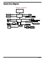
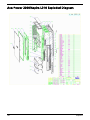
System Block Diagram
Block Diagram
LGA775 Processor
Socket T
800/533 FSB
DDRII SDRAM CONN 0
DDR2 CH:A
533/667MHZ
RGB Output
SDVO
DDRII SDRAM CONN 1
VGA CONN * 1
GMCH
946GZ
DDR2 CH:B
CH7021A-TEF
S-VIDEO
CH7307B-DE
DVI
TV CONN * 1
DVI CONN * 1
DMI
PCI V2.3 / 33MHZ
SATA-II CONN *2
MINI PCI
INTEGRATED SATA*2
ICH7
TSB43AB23PDT
1394 header * 1
ODD
HDA
RJ45
Azalia 6 Ports CONN*1
REALTEK
ALC888-GR
88E8056
Front Audio Header*1
BACK PANEL CONN => 4 Port
FWH
*8 USB ( V2.0 EHCI / V1.1 OHCI )
Mini card
2 USB2.0 PORTS
2 USB2.0 PORTS
4Mb FLASH
FRONT PANEL Header * 4 => 4 Ports
SIO
ITE IT8718
6
LPC BUS V1.0 / 33MHZ
SPI
2 Headers
FRONT PANEL 2 Ports
2 Headers
FRONT PANEL 2 Ports
SPI FLASH
Chapter 1
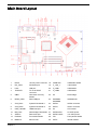
Main Board Layout
1
DCIN1
19V DC power connector 18
FUSB1394
USB&1394 header
2
DVI_VGA1
DVI&VGA port
19
F_1394_1
1394 header
3
LAN1
LAN port
20
F_USB1
USB header
4
TVSPDIF1
TV out & SPDIF
connector
21
F_USB2
USB header
5
OBR1
One button recovery
header
22
U5
North bridge
6
REAR_USB1
Rear USB port
23
SODIMM1.
SODIMM2
SODIMM slot
7
SYS_FAN1
System FAN header 1
24
SATA2
SATA2 connector
8
SYS_FAN2
System FAN header 2
25
SATA1
SATA1 connector
9
USB_1394CN1
USB&1394 port
26
U3
CPU socket
10
NB_FAN1
North bridge FAN header 27
SATAP5CN1
5V SATA power
11
AUDIO1
Rear audio port
28
SATAP12CN1
12V SATA power
12
FAUDIO1
Front audio header
29
FP1
Front pannel header
13
MINIPCI1
Mini PCI slot
30
INTR1
intruder header
Chapter 1
7
8
14
MINIPCIE
Mini PCIE slot
31
IDE1
IDE connector
15
16
U8
South bridge
32
U9
BIOS socket
MINIDIN1
Mini DIN header
33
BAT1
Battery header
17
CLR_CMOS1
clear CMOS header
Chapter 1
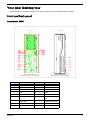
Your Acer Desktop tour
After knowing your computer features, let us show you around your new Veriton series computer.
Front and back panel
AcerPower 2000
#
Component
#
Component
1
Power DC-In
10
2
DVI
11
Audio jack
3
VGA
12
Audio jack
4
LAN
15
USB
5
USB
16
USB
6
USB
17
Audio-out/Line-out
jack
7
Audio jack
18
Microphone-in jack
8
Audio jack
19
USB
9
Audio jack
20
USB
Chapter 1
Audio jack
9
Aspire L310
#
1
10
Component
Power DC-in
#
13
Component
1394 port
2
DVI
14
TV port
3
VGA
15
Audio-in
4
LAN
16
Audio-out
5
USB
17
1394 port
6
USB
18
Card reader
7
Audio jack
19
USB
8
Audio jack
20
USB
9
Audio jack
21
TV port
10
Audio jack
22
S-video
11
Audio jack
23
TV-out
12
Audio jack
24
SPDIF
Chapter 1
System Peripherals
The Aspire T630 and AcerPower F3 computer consist of the system itself, and system peripherals, like a
mouse, keyboard and a set of speakers (optional). This section provides a brief description of the basic
system peripherals.
Mouse (PS/2 or USB, manufacturing option)
The included mouse is a standard two-button wheel mouse. Connect the mouse to the PS/2 mouse port or
USB port on the back panel of the system.
Keyboard (PS/2 or USB, manufacturing option)
Connect the keyboard to the PS/2 keyboard port or USB port on the back panel of the system.
Speakers
For systems bundled with speakers, before powering on the system, connect the speaker cable to the audio
out (external speaker) port on the back panel of the system.
For more detailed information about the speakers, please refer to the included operating instructions.
NOTE: speakers are optional and the appearance might be different depending on the actual product.
Chapter 1
11
12
Chapter 1
Acer Empowering Technology
Acer’s innovative Empowering Technology makes it easy for you to access frequently used functions and
manage your new Acer notebook. It features the following handy utilities:
•
•
•
•
•
•
Acer eSettings Management accesses system information and adjusts settings easily.
Acer eLock Management (for slected models) limits access to external storage media.
Acer eDataSecurity Management protects data with passwords and advanced encryption algorithms.
Acer ePerformance Management improves system performance by optimizing disk space, memory and
registry settings.
Acer eAcoustics Management offers a useful tool to balance your computing power needs with your
desired level of quietness.
Acer eRecovery Management backs up and recovers data flexibly, reliably and completely.
For more information, press the <
> key to launch the Empowering Technology menu, then click on the
appropriate utility and select the Help or Tutorial function.
NOTE: For AcerPower 2000, Acer Empowering Technology includes the following utilities: Acer Empowering
framework utility, Acer eSettings Management, Acer eLock management, Acer eDataSecurity
Management, Acer ePerformance Management, Acer eAcoustics Management, Acer eRecovery
Management. However, for Aspire L310, Acer Empowering Technology contains: Acer Empowering
framework utility, Acer eRecovery Management, Acer eDataSecurity Management and Acer
ePerformance Management.
Empowering Technology password
Before using Acer eLock Management and Acer eRecovery Management, you must initalize the Empowering
Technology password. Right-click on the Empowering Technology toolbard and select “Password Setup” to do
so. If you do not initialize the Empowering Technology password, you will be prompted to do so when running
Acer eLock Management or Acer eRecovery Management for the first time.
Acer eSettings Management
Acer eSettings Management allows you to inspect hardware specifications, change BIOS passwords or other
Windows settings, and to monitor the system health status.
Acer eSettings Management also:
•
•
Provides a simple graphical user interface for navigating.
Displays general system status and advanced monitoring for power users on Acer computer.
Chapter 1
13
Acer eLock Management
Acer eLock Management is a security utility that allows you to lock your removable data, optical and floppy
drives to ensure that data can’t be stolen while your notebook is unattended.
•
•
•
•
Removable data devices - includes USB disk drives, USB pen drives, USB flash drives, USB MP3 drives,
USB memory card readers, IEEE 1394 disk drives and any other removable disk drives that can be
mounted as a file system when plugged into the system.
Optical drive deivces - includes any kind of CD-ROM or DVD-ROM drives.
Floppy disk drives - 3.5-inch disks only.
Interfaces - includes serial ports, parallel port, infrared (IR), and Bletooth.
To activate Acer eLock Management, a password must be set first. Once set, you can apply locks to any of the
devices. Lock(s) will immediately be set without any reboot necessary, and will remain locked after rebooting,
until unlocked.
NOTE: If you lose your password, there is no method to reset it except by reformatting your notebook or taking
your notebook to anAcer Customer Serivce Center. Be sure to remember or write down your password.
14
Chapter 1
Acer eDataSecurity Management
Acer eDataSecurity Management is handy file encryption utility that protexts your files from being accessed by
unauthorized persons. It is conveniently integrated with Windows explorer as a shell extension for quick and
easy data encryption/decryption and also supports on-the-fly file encryption for MSN Messager and Microsoft
Outlook.
The Acer eDataSecurity Management setup wizard will prompt you for a suvervisor password and default
encryption. This encryption will be used to encrypt files by default, or you can choose to enter your won filespecific password when encrypting a file.
NOTE: The password used encrypt a file is the unique key that the system needs to decrypt it. If you lose the
password, the supervisor password is the only other key capable of decrypting the file. If you lose both
passwords, there will be no way to decrypt your encryped file! Be sure to safeguard all related
passwords!
Chapter 1
15
16
Chapter 1
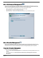
Acer ePerformance Management
Acer ePerformance Management is a system optimization tool that boosts the performance of your Acer
notebook. It provides and express optimization method to release unused memory and disk space quickly.
The user can also enable advanced options for full control over the following option:
•
•
•
Memory optimization - releases unused memory and check usage.
Disk optimization - removes unneeded items and files.
Speed optimization - improves the usability and performance of your Windows XP system.
Acer eAcoustics Management
Acer eAcoustics Management offers you a useful tool to balance your computing power needs with your
desired level of quietness. By reducing the processor speed for tasks that require less processing, the CPU
and system fans can run slower, thus reducing the amount of sound generated by tehse components.
Using Acer eAcoustics Management
To launch Acer eAcoustics Management
•
•
Click on the Acer eAcoustics Management icon in the Empowering Technology toolbard shown on your
desktop.
From the Start menu, go to (All) Programs>Acer Empowering Technology>Acer eAcoustics
Management.
Chapter 1
17
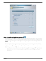
This will open Acer eAcoustics Management main page.
Acer eAcoustics Management Main Page
Listed on the main page are two options for Acer eAcoustics Management, labeled as Quiet and Professional.
Select the mode that suits your working requirements best, and exit the utility to apply the settings.
Quiet
Use this mode for tasks that require low processing power, like word processing, Web browsing, and instant
messaging. This mode creates the lowest audio disturbance.
Professional Mode
Use this mode for processing-intensive tasks, when you require full-speed operation.
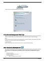
Acer eRecovery Management
Acer eRecovery Management is a powerful utility that does away with the need for recovery disks provided by
the manufacturer. The Acer eRecovery Management utility occupies space in a hidden partition on your
system’s HDD. User-created backups are stored on D:\ drive. Acer eRecovery Management provides you
with:
Password protection.
Recovery of applications and drivers.
Image/data backup:
•
•
•
T
18
Back up to HDD (set recovery point).
Chapter 1
T
•
Back up to CD/DVD.
Image/data recovery tools:
T
Recover from a hidden partition (factory defaults).
T
Recover from the HDD (most recent user-defined recovery point).
T
Recover from CD/DVD.
For more information, please refer to “Acer eRecovery Management”
NOTE: If your computer did not come with a Recovery CD or System CD, please use Acer eRecovery
Management’s “System backup to optical disk” feature to burn a backup image to CD or DVD. To
ensure the best results when recovering your system using a CD or Acer eRecovery Management,
detach all peripherals (except the external Acer ODD, if your computer has one), including your Acer
ezDock.
Chapter 1
19
Hardware Specifications and Configurations
System Board Major Chip
Item
Specification
System Core Logic
North bridge: Intel (R) 946Gz
South bridge: Intel (R) ICH7
Super I/O Controller
ITE IT8718F
LAN Controller
Marvell 88E8056-A2-NNC1C00
Memory Controller
Built-in north bridge: Intel (R) 946Gz
SATA Controller
Built-in ICH7
1394 Controller
TI TSB43AB23PDT
Audio Controller
Audio codec: Realtek ALC888-GR
VGA Controller
Built-in Intel (R) 946Gz
Keyboard Controller
ITE IT8718DX
Processor
Item
Specification
Type
Intel Celeron D 352 and 356(Cedar Mill ICP) 2006 FMB(65W)
Intel Pentium 631,641,651 and 661(Cedar Mill) 2006
FMB(65W)
Slot
Socket 775
Speed
Depends on CPU, which is local configured
Bus Frequency
533/800 MHz
Voltage
Processor voltage can be detected by any system without
setting any jumper
BIOS
Item
BIOS code programmer
Specification
Award
BIOS version
20
BIOS ROM size
4MB
BIOS ROM package
32-pin PLCC package
Support protocol
PCIX 1.0,PCI 2.2,APM 1.2,VESA/DPMS (VBE/PM V1.1),
SMBIOS 2.3, E-IDE 1.1, ACPI 1.0b,ESCD1.03, PnP 1.0a,
Bootable CD-ROM 1.0, USB 1.1~ USB 2.0, UHCI 1.0, ANSI
ATA 3.0 ATAPI
Boot from CD-ROM feature
Yes
Support to LS-120 drive
Yes
Support to BIOS boot block feature
Yes
BIOS Password Control
Yes
Chapter 1
BIOS Hotkey List
Hotkey
Function
c
Description
Enter BIOS Setup Utility
Press while the system is booting to
enter BIOS Setup Utility.
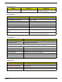
System Memory
Item
Specification
Memory Slot Number
2 Slots
Supported Memory Size per Slot
256 MB ~ 1GB
Supported Maximum Memory Size
2GB
Supported Memory Speed
533/667MHz
Supported memory voltage
1.8V
Support memory module package
so-DIMM
Support to parity check feature
Yes
Support to Error Correction Code (ECC)
feature
Yes
Memory module combinations
You can install memory modules in any combination as
long as they match the above specifications.
Cache Memory
Item
Specification
First-Level Cache Configurations
Cache function control
Enable/Disable by BIOS Setup
Second-Level Cache Configurations
The information below is only applicable to system installed with a Pentium 4 processor
Tag RAM Location
On Processor
L2 Cache RAM Location
On Processor
L2 Cache RAM type
PBSRAM (Pipelined-burst Synchronous RAM)
L2 Cache RAM size
Depends on CPU, which is local configured
L2 Cache RAM speed
Full of the processor core clock frequency (Advanced Transfer Cache)
L2 Cache function control
Enable/Disable by BIOS Setup
L2 Cache scheme
Fixed in write-back
LAN Interface
Item
Specification
LAN Controller
Marvell 88E8056
LAN Controller Resident Bus
PCI Express Bus
LAN Port
ONE RJ-45 on board
Function Control
Enable/Disable by BIOS Setup
Chapter 1
21
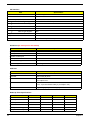
IDE Interface
Item
Specification
IDE Controller
Built-in Intel (R) ICH7
IDE Controller Resident Bus
PCI bus
Number 40 pin PATA slot
1
T
Device Type Support
Combo, DVD Dual/DVD supermulti
T
Transfer Rate Support
PIO 0/1/2/3/4
T
ATA Mode
33/66/100
Number STAT IDE slot
2
Device Type Support
T
HDD
Supports LS-120
Yes
Supports bootable CD-ROM
Yes
Function Control
Enable/Disable by BIOS setup
Serial Port (No serial port for this model)
Item
Specification
Serial port controller
LPC47M182
Serial port controller resident bus
LPC Bus
Number of serial port
1
Serial port location
Rear panel
16550 UART support
Yes
Connector type
9-pin D-type female connector
USB Port
Item
Specification
Universal HCI
USB 2.0/1.1
Controller
Built-in Intel (R) ICH7
Number of the connectors
8 for AcerPower 2000
6 for Aspire L310
Location
Rear : 4
Front : 4 (for AcerPower 2000); 2 (for Aspire L310)
USB Class
Support legacy keyboard for legacy mode
Wake-up Event Specifications
Device
Power Button
22
S1
S3
S4
S5
Enabled
Enabled
Enabled
Enabled
PS2 Keyboard
Disabled
Disabled
Disabled
Disabled
USB Keyboard
Disabled
Disabled
N/A
N/A
PME
Disabled
Disabled
Disabled
Disabled
WOR (wake on Ring)
Disabled
Disabled
Disabled
Disabled
RTC (real time clock)
Disabled
Disabled
Disabled
Disabled
Chapter 1
Thermal Design
Item
Description
Thermal Design
T
Thermal solutin should cover Intel (R) 2006 FMB (65W)
requirement
T
2 4-pin smart fan for system
T
1 2-pin fan for north bridge
T
Provision for optional secondary fan
T
Adequate venting in the front of chassis
T
Adequate venting in the rear of chassis
Memory Address Map
Address
Size
Function
0000000 - 009FFFF
640 KB System Memory
Onboard DRAM
00A0000-00BFFFF
128 KB Video RAM
Reserved for Graphics Display
Buffer
Non-Cacheable
00C0000-00CFFFF
32 KB I/O Expansion ROM
Reserved for ROM on I/O
Adapters
00D0000-00D3FFF
16 KB I/O Expansion ROM
Reserved for ROM on I/O
Adapters
00D4000-00D7FFF
16 KB I/O Expansion ROM
Reserved for ROM on I/O
Adapters
00D8000-00DBFFF
16 KB I/O Expansion ROM
Reserved for ROM on I/O
Adapters
00DC000-00DFFFF
16 KB I/O Expansion ROM
Reserved for ROM on I/O
Adapters
00E0000-00E7FFF
32 KB for SCSI BIOS
Reserved for SCSI BIOS
00E8000-00EFFFF
32 KB
Reserved Onboard
00F0000-00FFFFF
64 KB BIOS
System ROM BIOS (ROM)
System RAM BIOS (DRAM)
0100000-0F9FFFF
System Memory
Onboard DRAM
0FA0000-0FFFFFF
384 KB I/O Card Memory
Reserved for Memory Map
I/O Card
Non-Cacheable
1000000-FFFFFFF
System Memory
Onboard DRAM
PCI INTx# and IDSEL Assignment Map
PCI INTx #
INTA#
PCI Devices
ADIMM-slot
Device IDSEL: ADxx
N
INTB#
PCI-Slot1
AD16
INTC#
PCI-Slot2
AD17
Chapter 1
23
I/O Address Map
Hex Range
Devices
000-01F
020-021
040-043
060-060
061-061
070-071
080-08F
0A0-0A1
0C0-0DF
0F0-0FF
170-177
1F0-1F7
278-27F
2F8-2FF
378-37F
3F0-3F5
3F6-3F6
3F7-3F7
3F8-3FF
0CF8
0CFC
778-77A
DMA Controller-1
Interrupt Controller-1
System Timer
Keyboard Controller 8742
System Speaker
CMOS RAM Address and Real Time Clock
DMA Page Register
Interrupt Controller-2
DMA Controller-2
Math Co-Processor
Secondary IDE
Primary IDE
Parallel Printer Port 2
Serial Asynchronous Port 2
Parallel Printer Port 1
Floppy Disk Controller
Secondary IDE
Primary IDE
Serial Asynchronous Port 1
Configuration Address Register
Configuration Data Register
Parallel Printer Port 1
IRQ Assignment Map
IRQx
System Devices
Add-On-Card Devices
IRQ0
Timer
N
IRQ1
Keyboard
N
IRQ2
Reserved
N
IRQ3
Serial Port 2
Reserved
IRQ4
Serial Port 1
Reserved
IRQ5
Reserved
Reserved
IRQ6
Floppy Disk
Reserved
IRQ7
Parallel Port
Reserved
IRQ8
Real Time Clock
N
IRQ9
N
Reserved
IRQ10
N
Reserved
IRQ11
N
Reserved
IRQ12
PS/2 Mouse
Reserved
IRQ13
Numeric Processor
N
IRQ14
Embedded Hard Disk
Reserved
IRQ15
Reserved
Reserved
NOTE: N - Not be used
24
Chapter 1
DRQ Assignment Map
DRQx
System Devices
Add-On-Card Devices
DRQ0
N
Reserved
DRQ1
N
Reserved
DRQ2
FDD
N
DRQ3
N
Reserved
DRQ4
Cascade
N
DRQ5
N
Reserved
DRQ6
N
Reserved
DRQ7
N
Reserved
NOTE: N - Not be used
Environmental Requirements
Item
Specifications
Temperature
Operating
+5°C ~ +35°C
Non-operating
-20 ~ +60°C (Storage package), -10°C~+60°C (un-package)
Humidity
Operating
15% to 80% RH, non-condensing
Non-operating
10% to 90% RH, non-condensing at 40°C
Vibration
Operating (unpacked)
5 ~ 500Hz, 2.20g RMS random,10 minutes per axis in all 3 axes
Non-operating (packed)
5 ~ 500Hz, 1.09g RMS random,1 hour per axis in all 3 axes
Shock Operating
Half sine, 2g 11m seconds
Drop Test
Drop Test
Definition
The protection ability of packing & cushion must be capable of withstanding, with no physical
or functional demage, mechanical impact from height-specific drops.
Test Standard
Package Cross Weight
Drop Height
Not of Drop
KGs
lbs
CM
Inch
0~9.1
0~20
76
30
10
9.1~18.2
20~40
61
24
10
18.2~27.3
40~60
46
18
10
27.3~45.4
60~100
31
12
10
10 drops : one corner, three edges, six surfaces
Chapter 1
25
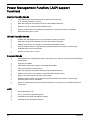
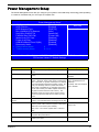
Power Management Function ( ACPI support
function)
Device Standby Mode
T
Independent power management timer for hard disk drive devices
(0-15 minutes, time step=1 minute).
T
Hard disk drive goes into Standby mode (for ATA standard interface).
T
Disable V-sync to control the VESA DPMS monitor.
T
Resume method: device activated (Keyboard for DOS, keyboard & mouse for Windows).
T
Resume recovery time: 3-5 sec.
Global Standby Mode
T
Global power management timer (2-120 minutes, time step=10 minute).
T
Hard disk drive goes into Standby mode (for ATA standard interface).
T
Disable H-sync and V-sync signals to control the VESA DPMS monitor.
T
Resume method: Return to original state by pushing external switch button, modem ring in,
keyboard and mouse for APM mode.
T
Resume recovery time: 7-10 sec.
Suspend Mode
T
Independent power management timer (2-120 minutes, time step=10 minutes) or pushing external
switch button.
T
CPU goes into SMM.
T
CPU asserts STPCLK# and goes into the Stop Grant State.
T
LED on the panel turns amber colour.
T
Hard disk drive goes into SLEEP mode (for ATA standard interface).
T
Disable H-sync and V-sync signals to control the VESA DPMS monitor.
T
Ultra I/O and VGA chip go into power saving mode.
T
Resume method: Return to original state by pushing external switch button, modem ring in,
keyboard and mouse for APM mode.
T
Return to original state by pushing external switch button, modem ring in and USB keyboard for
ACPI mode.
ACPI
26
T
ACPI specification 1.0b.
T
S0, S1, S3 and S5 sleep state support.
T
On board device power management support.
T
On board device configuration support.
Chapter 1
Dual Channel
VT x800 series support the Dual Channel Technology. After operating the dual channel
technology, the bandwidth of memory bus will add double up to 4GB/s.
The mainboard inculdes 4 DIMM slots, and each channel has two DIMM sockets as following:
T
Channel A : DDR1, DDR3
T
Channel B : DDR2 , DDR4
If you want to operate the Dual Channel Technology, please note the following explanations due to
the limitation of Intel chipset specifications.
Memory Number
Description
1
Only one DDR memory module is
installed ?
The Dual Channel Technology can’t operate when only
one DDR memory module is installed.
2
Two DDR memory modules are
installed ( the same memory size
and type) ?
The Dual Channel Technology will operate when two
memory modules are inserted individually into Channel A
and B. If you install two memory modules in the same
channel, the Dual Channel Technology will not operate.
3
Three DDR memory modules are
installed ?
Pleae note that the Dual Channel Technology will not
operate when three DDR memory modules are installed;
part of them will not be detected.
4
Four DDR memory modules are
installed ?
If you install four memory modules at the same time, the
Dual Channel Technology will operate only when those
modules have the same size and type.
NOTE: We strongly recommend user to slot two DDR memory modules into the DIMMs with the same color in
order for Dual Channel Technology to work.
The following tables include all memory-installed combination types:
Dual Channel Technology (DS: Double Side, SS: Single Side)
DDR1
2 memory modules
4 memory modules
DDR2
DDR3
DDR4
DS/SS
X
DS/SS
X
X
DS/SS
X
DS/SS
DS/SS
DS/SS
DS/SS
DS/SS
Don’t operate Dual Channel Technology (DS:Double Side, SS: Single Side)
DDR1
1 memory module
2 memory module
3 memory module
Chapter 1
DDR2
DDR3
DDR4
DS/SS
X
X
X
X
DS/SS
X
X
X
X
DS/SS
X
X
X
X
DS/SS
DS/SS
DS/SS
X
X
X
X
DS/SS
DS/SS
DS/SS
DS/SS
DS/SS
X
DS/SS
DS/SS
X
DS/SS
DS/SS
X
DS/SS
DS/SS
X
DS/SS
DS/SS
DS/SS
27
28
Chapter 1
Chapter 2
System Utilities
BIOS (Basic Input and Output System) includes a CMOS SETUP utility which allows user to
configure required setting or to active certain system features.
The CMOS SETUP saves the configuration in the CMOS SRAM of the mainboard. When the power is turned
off, the battery on the mainboard supplies the necessary power to the CMOS SRAM.
When the power is turned on, pushing the <Del> button during the BIOS POST (Power-On Self Test) will take
you to the CMOS SETUP screen. You can enter the BIOS setup screen by pressing “Ctrl+F1”. When setting
up BIOS for the first time, it is recommended that you save the current BIOS to a disk in the event that BIOS
needs to be reset to its original settings.
Q-Flash allows the user to quickly and easily update or backup BIOS without entering the operating system.
BIOS is a Window s-based utility that doesn’t required users to boot to DOS before upgrading BIOS but
directly download and update BIOS from the Internet.
Control Keys
Item
Description
wxyz
Move to selection
e
Select Item
^
Main Menu: Quit and not save changes into CMOS Status Page Setup
Menu and Option Page Setup Menu, Exit current page and return to
Main Menu.
{
Increase the numeric value or make changes
}
Decrease the numeric value or make changes
l
General help, only for Status Page Setup Menu and Option Page
Setup Menu
m
Item Help
p
Restore the previous CMOS value from CMOS, only for option Page
Setup Menu
r
Load the Optimized Defaults
t
System Information
u
Save all the CMOS changes, only for Main Menu
NOTE: Main Menu: This is the online description of the highlighted setup functions is displayed at the bottom
of the screen.
NOTE: Status Page Setup Menu/ Option Page Setup Menu: Press F1 to pop up a small help window that
describes the appropriate keys to use and the possible selections for the highlighted item. To exit the
Help Window press <Esc>.
Chapter 2
29
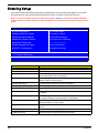
Entering Setup
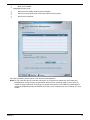
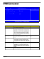
Once enter Award BIOS CMOS Setup Utility, the Main Menu (as figure below) will appear on the screen.
Use arrow keys to select among the items and press <Enter> to accept or enter the sub-menu.
Note: If you can’t find the setting you want, please press “Alt+F4” to search the advanced option
hidden. As for the hidden options, we have annotations following those with further setting screen
menu.
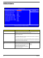
Phoenix - AwardBIOS CMOS Setup Utility
XProduct Information
XPC Health Status
XStandard CMOS Features
XFrequency Control
XAdvanced BIOS Features
Load Default Settings
XAdvanced Chipset Features
Set Supervisor Password
XIntegrated Peripherals
XPower Management Setup
Save & Exit Setup
XPnP/PCI Configurations
Exit Without Saving
Esc:Quit
F10: Save & Exit Setup
Parameter
Product Information
30
x Set User Password
KLIJ : Select Item
Description
This page shows the relevant information of the mainboard
Standard CMOS Features
This setup page includes all the items in standard compatible BIOS
Advanced BIOS Features
The values for the chipset can be changed through this menu, and the
system performance can be optimized.
Advanced Chipset Features
This setup page allows user to configure the advanced chipset
settings, such as memory timing.
Integrated Peripherals
This setup page includes all onboard peripherals
Power Management Setup
This setup page includes all the items of Green function features
PnP/PCI Configuration
This setup page includes all configurations of PCI&PnP ISA resources
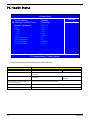
PC Health Status
This setup page is the System auto detect Temperature, voltage, fan
and speed
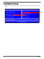
Load Default Settings
Default Settings indicates the value of the system parameters which
the system would be in best performance configuration
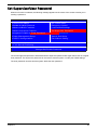
Set Supervisor Password
Change, set or disable password. It allows you to limit access to the
system and Setup, or just to Setup
Set User Password
Change, set or disable password. It allows you to limit access to the
system
Save & Exit Setup
Save CMOS value settings to CMOS and exit setup
Exit Without Saving
Abandon all CMOS value changes and exit setup
Chapter 2
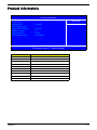
Product Informatoin
Product Name
System S/N
Main Board ID
Asset Tag Number
System BIOS Version
SMBIOS Version
System BIOS ID
BIOS Release Date
Phoenix - AwardBIOS CMOS Setup Utility
Product Information
AcerPower 2000/Aspire L310
Item Help
Menu Level
F1946GZ
X
6.00 PG
2.4
R01-B1
2006/09/05
KLIJ :Move Enter: Select +/-/PU/PD :Value F10:Save ESC:Exit F1:General Help
F5:Previous Values F7:Default Settings
Parameter
Description
System Product Name
This item lists the product name
MB Product Name
This item lists the main board product name.
System S/N
This item lists the system serial number
MB S/N
This item lists the main board serial number.
System Manufacture Name
This item lists the system manufacturer name
MB Manufacture Name
This item lists the main board manufacturer name.
System BIOS Version
This item lists the system BIOS version
SMBIOS Version
This item lists the system SMBIOS version
System BIOS ID
This item lists the system BIOS ID
BIOS Release Date
This item lists the BIOS release date
Chapter 2
31
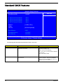
Standard CMOS Features
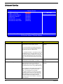
Date (mm:dd:yy):
Time (hh:mm:ss):
Phoenix - AwardBIOS CMOS Setup Utility
Standard CMOS Features
Wed Aug 23 2006
11:08:43
Item Help
Menu Level X
XSATA Channel 0 Master
XSATA Channel 0 Master
XSATA Channel 0 Master
XSATA Channel 0 Master
Drive A
Video
Halt On
Base Memory
Extended Memory
Total Memory
None
None
None
None
[1.44M, 3.5 in]
[All, But Keyboard]
640K
1021952K
1022976K
KLIJ :Move Enter: Select +/-/Pu/PD :Value F10:Save ESC:Exit F1:General Help
F5:Previous Values F7:Default Settings
The following table describes the parameters found in this menu:
Parameter
Date
Description
Lets you set the date following the weekdaymonth-day-year format
Options
Week : from Sun. to Sat., determined by
BIOS and is display only
Month : from Jan. through Dec.
Day : from 1 to 31 ( or the maximum allowed
in the month)
Year : from 1999 to 2098
Time
32
Lets you set the time following the hour-minutesecond format
The items format is <hour>
<minut><second>. The time is calculated
base on the 24-hour military-time clock. For
example, 1 p.m. is 13:00:00
Chapter 2
Parameter
SATA channel 0/1 Master,
Slave
Description
Allows you to configure the hard disk drive
connected to the master port of SATA channel.
To enter the SATA Master or Slave setup, press
[Enter].
Options
SATA HDD Auto-Detection Press [Enter] to
select this option for automatic device
detection.
SATA Primary/Secondary Master, Slave IDE
Device Setup. You can use one of three
methods:
Auto : Allows BIOS to automatically detect
SATA devices during POST (default)
None : Select this if no IDE devices are
used and the system will skip the automatic
detection step and allow for faster system
start up
Manual : User can manually input the
correct settings
Access Mode : Use this to set the access
mode for the hard drive. the four options are:
CHS/LBA/Large/Auto (default: Auto)
* Cylinder : Number of cylinders
* Head : Number of heads
* Precomp : Write precomp
* Landing Zone : Landing Zone
Sector : Number of sectors
Access Mode allows you to select the access
mode. The options are CHS, LBA, Large,
and Auto.
Drive A
The category identifies the types of floppy disk
drive A that has been installed in the computer.
None : No floppy drive installed
360K, 5.25” : 5.25 inch PC type standard
drive ; 360Kbyte capacity
1.2M, 5.25” : 5.25 inch AT-type high-density
drive; 1.2M byte capacity (3.5 inch when 3
Mode is Enabled)
720K, 3.5” : 3.5 inch double-sided drive;
720Kbyte capacity
1.44M, 3.5” : 3.5 inch double-sided drive;
1.44Mbyte capacity
2.88M, 3.5” : 3.5 inch double-sided drive;
2.88Mbyte capacity
Halt On
This parameter enables you to control the
system stops in case of Power On Self Test
errors (POST)
No Errors : The system boot will not stop for
any error that may be detected and you will
be prompted
All Errors : Whenever the BIOS detects a
non-fatal error the system will be stopped
All, But Keyboard : The system boot will not
stop for a keyboard error; it will stop for all
other errors (Default value)
All, But Diskette : The system boot will not
stop for a disk error; it will stop for all other
errors
All, But Disk/Key : The system boot will not
stop for a keyboard or disk error; it will stop
for all other errors.
Base Memory
Typically 640 KB. Also called conventional
memory. The DOS operating system and
conventional applications use this area.
N/A
Extended Memory
Above the 1-MB boundary. Early IBM personal
computers could not use memory above 1 MB,
but current PCs and their software can use
extended memory.
N/A
Chapter 2
33
Parameter
Total Memory
34
Description
Base + Upper + Extended = Total Memory.
Options
N/A
Chapter 2
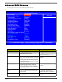
Advanced BIOS Features
The following screen shows the Advanced BIOS Features:
Phoenix - AwardBIOS CMOS Setup Utility
Advanced BIOS Features
X CPU Feature
[Press Enter]
X Hard Disk Boot Priority
[Press Enter]
Virus Warning
[Disabled]
Quick Power On Self Test
[Enable]
First Boot Device
[Hard Disk]
Second Boot Device
[CDROM]
Third Boot Device
[Floppy]
Boot Other Device
[Enabled]
Boot Up Floppy Seek
[Disabled]
Boot Up NumLock Status
[On]
Gate A20 Option
[Fast]
Security Option
[Setup]
APCI Mode
[Enabled]
MPS Version Control For OS[1.4]
Console Redirection
Disabled
x Baud Rate
19200
Agent after boot
Enabled
Silent Boot
[Enabled]
Configuration Table
[Disabled]
Item Help
Menu Level X
KLIJ :Move Enter: Select +/-/PU/PD :Value F10:Save ESC:Exit F1:General Help
F5:Previous Values F7:Default Settings
Parameter
Description
Options
CPU Feature
Press Enter to display CPU feature
N/A
Hard Disk Boot Priority
Press [Enter] to enter the sub menu to select
Hard Disk Boot Device Priority.
Use wx to select a device, then
press<+> to move it up, or < - > to
move it down the list.
Virus Warning
This feature allows you to enable the VIRUS
warning function for IDE Hard Disk boot sector
protection. If this function is enabled and there
is someone attempt to write data into this area,
BIOS will show a warning message on screen
and the alarm will beep.
Enabled
This feature allows the system to skip certain
tests while booting. When this function is
enabled, it will decrease the time needed to
boot the system, which means to quick power
on self test function
Enabled
First / Second / Third Boot
Device
The item allows you to set the sequence of boot
device where BIOS attempts to load the disk
operating system.
Floppy, LS120, Hard Disk, CD-ROM,
ZIP, USB-FDD, USB-ZIP, USBCDROM, USB-HDD, LAN, Disabled
Boot other Devices
This item allows you to enable or disable to boot
from other device
Enabled
Quick Power On Self Test
Chapter 2
Disabled
Disabled
Disabled
35
Parameter
Boot Up Floppy Seek
Boot Up NumLock Status
Gate A20 Option
Security Option
APCI Mode
Description
Options
When Enabled, the BIOS tests (seeks) floppy
drives to determine whether they have 40 or 80
tracks. Only 360-KB floppy drives have 40
tracks; drives with 720 KB, 1.2 MB, and 1.44
MB capacity all have 80 tracks. Because very
few modern PCs have 40-track floppy drives,
we recommend that you set this field to
Disabled to save time.
Enabled
This item allows you to enable or disable to set
keyboard is number keys or arrow keys
Enabled
Gate A20 refers to the way the system
addresses memory above 1 MB (extended
memory). When set to Fast, the system chipset
controls Gate A20. When set to Normal, a pin in
the keyboard controller controls Gate A20.
Setting Gate A20 to Fast improves system
speed, particularly with OS/2 and Windows.
Fast
If you have set a password, select whether the
password is required every time the System
boots, or only when you enter Setup.
Setup
This option is used to set up enable or disable
the APCI funtion
Enabled
Disabled
Disabled
Normal
System boots
Disabled
MPS Version Control For OS The BIOS supports versions 1.1 and 1.4 of the
Intel multiprocessor specification. Select the
version supported by the operating system
running on this computer.
1.4
Silent Boot
This features allows you to enable or disable if
the screen logo to display or no during POST
Enabled
This feature allows you to enable or disable if
showing summary screen or not
Enabled
Configuration Table
Disabled
Disabled
CPU Feature
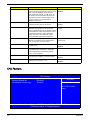
Phoenix - AwardBIOS CMOS Setup Utility
CPU Feature
C1E Function
[Auto]
Item Help
Execute Disable Bit
[Enabled]
Virtualization Technology
[Enable]
Menu Level X
CPU C1E Function
Select
KLIJ :Move Enter: Select +/-/PU/PD :Value F10:Save ESC:Exit F1:General Help
F5:Previous Value F7:Default Settings
36
Chapter 2
Parameter
C1E Function
Execute Disable Bit
Virtualization Technology
Chapter 2
Description
Options
CPU new added feature. System may hang
when SATA port 4 is in used. C1E function can
fix this problem.
Auto
Can improve protection against malicious
"buffer overflow" attacks when properly enabled
with Windows XP SP2.
Enabled
Virtualization enhanced by Intel Virtualization
Technology will allow a platform to run multiple
operating systems and applications in
independent partitions. With virtualization, one
computer system can function as multiple
operating systems. With processor and I/O
enhancements to Intel’s various platforms, Intel
Virtualization Technology can improve the
performance and robustness of today’s
software-only virtual machine solutions.
Enable
Disabled
Enable
Disabled
Disabled
37
Advanced Chipset Features
AMT BIOS Support
GbE LAN
SOL Support
IDE-R Support
Phoenix - AwardBIOS CMOS Setup Utility
Advanced Chipset Features
[Enabled]
Item Help
Enabled
Enabled
Menu Level X
Enabled
** VGA Setting **
PEG/Onchip VGA Control
On-Chip Frame Buffer Size
DVMT Mode
DVMT/FIXED Memory Size
[Auto]
[8MB]
[DVMT]
[128MB]
KLIJ :Move Enter: Select +/-/PU/PD :Value F10:Save ESC:Exit F1:General Help
F5:Previous Value F7:Default Settings
Parameter
AMT BIOS Support
Description
Enables or disables Intel (R) AMT (Active Management
Technology) BIOS supporting function. Please visit Intel (R)
website for more details. http://www.intel.com/technology/
manage/iamt/index.htm
Options
Disabled
Enabled
GbE LAN
Displays Gigabit Ethernet support is enabled or disabled.
SOL Support
Displays Serial-over-LAN function is enabled or disabled. Serial-over-LAN
provides a mechanism that enables the serial controller of a managed system to
be redirected over an IPMI (Intelligent Platform Management Interface) session
over IP. This enables remote console applications to provide access to textbased interfaces for BIOS, utilities, operating systems, and applications while
simultaneously providing access to IPMI platform management functions. SOL
is implemented as a payload type under the new payload capability in RMCP
plus.
IDE-R Support
Displays IDE RAID function is enabled or disabled. If you like to know more
details about IDE-R, please visit http://www.answers.com/topic/ide-raid
PEG/Onchip VGA Control
This BIOS feature is found in motherboards that have a
built-in graphics processor as well as a PCI Express port. It
allows you to select whether to use the onboard graphics
processor or the PCI Express card.
PEG Port
Onchip VGA
Auto
When set to Onchip VGA, the motherboard boots up using
the onboard graphics processor, even when a PCI Express
graphics card is installed.
When set to PEG Port, the motherboard boots up using the
PCI Express graphics card, if one is installed. Otherwise, it
defaults to the onboard graphics processor.
When set to Auto, the BIOS checks to see if a PCI Express
graphics card is installed. If it detects that a PCI Express
graphics card is present, the motherboard boots up using
that card. Otherwise, it defaults to the onboard graphics
processor.
38
Chapter 2
Parameter
Description
Options
On-Chip Frame Buffer Size
This BIOS feature controls the amount of system memory
that is allocated to the integrated graphics processor when
the system boots up. Please visit http://www.rojakpot.com/
showFreeBOG.aspx?lang=0&bogno=325 for more detailed
settings.
1MB, 4MB, 8MB,
16MB, 32MB,
64MB, 128MB (for
UMA)
The BIOS feature that controls all this is the DVMT Mode
BIOS feature. It allows you to select the DVMT operating
mode.
Fixed Mode
DVMT Mode
When set to Fixed Mode , the graphics driver will reserve a
fixed portion of the system memory as graphics memory.
This ensures that the graphics processor has a guaranteed
amount of graphics memory but the downside is once
allocated, this memory cannot be used by the operating
system even when it is not in use.
1MB, 8MB (for
DVMT)
DVMT Mode
Combo Mode
When set to DVMT Mode, the graphics chip will
dynamically allocate system memory as graphics memory,
according to system and graphics requirements. The
system memory is allocated as graphics memory when
graphics-intensive applications are running but when the
need for graphics memory drops, the allocated graphics
memory can be released to the operating system for other
uses.
When set to Combo Mode , the graphics driver will allocate
a fixed amount of memory as dedicated graphics memory,
as well as allow more system memory to be dynamically
allocated between the graphics processor and the
operating system.
It is recommended that you set this BIOS feature to DVMT
Mode for maximum performance. Setting it to DVMT Mode
ensures that system memory is dynamically allocated for
optimal balance between graphics and system
performance.
DVMT/FIXED Memory Size
It allows you to set the maximum amount of system
memory that can be allocated as graphics memory, but only
for the Fixed or DVMT operating modes. When the DVMT +
Fixed mode is selected, this BIOS feature is grayed out
because when in that operating mode, the graphics driver
automatically allocates a total of 128MB of graphics
memory.
64MB
128MB
When set to 64MB, up to 64MB of system memory can be
used as graphics memory.
When set to 128MB, up to 128MB of system memory can
be used as graphics memory.
Chapter 2
39
Integrated Peripherals
All onboard peripherals can be set up through this menu.
For AcerPower 2000
Phoenix - AwardBIOS CMOS Setup Utility
Integrated Peripherals
USB 2.0 Support
[Enabled]
Item Help
Onboard Audio
[Enabled]
Menu Level X
Onboard LAN function
[Enabled]
This entry is for disable/
enable EHCI controller
only. This BIOS itself
may/may not have high
speed USB support built
in, the support will be
automatically turn on
high speed device were
attached
KLIJ :Move Enter: Select +/-/PU/PD :Value F10:Save ESC:Exit F1:General Help
F5:Previous Values F7:Default Settings
For Aspire L310
Phoenix - AwardBIOS CMOS Setup Utility
Integrated Peripherals
USB 2.0 Support
[Enabled]
Item Help
Onboard Audio
[Enabled]
Onboard LAN function
[Enabled]
Menu Level X
Onboard 1394 function
[Enabled]
This entry is for disable/
enable EHCI controller
only. This BIOS itself
may/may not have high
speed USB support built
in, the support will be
automatically turn on
high speed device were
attached
KLIJ :Move Enter: Select +/-/PU/PD :Value F10:Save ESC:Exit F1:General Help
F5:Previous Values F7:Default Settings
40
Chapter 2
Parameter
Description
Options
USB 2.0 Support
Enables or disables USB 2.0 support function.
Onboard Audio
Select Enabled to use the audio capabilities of your system. Most of the following
fields do not appear when this field is Disabled.
Onboard LAN function
Select Enabled to use the LAN capabilities of your system.
Onboard 1394 function
Select Enalbed to use the 1394 capabilities of your system.
Chapter 2
41
OnChip IDE Device
Phoenix - AwardBIOS CMOS Setup Utility
OnChip IDE Device
IDE HDD Block Mode
[Press Enter]
IDE DMA transfer access
[Press Enter]
IDE Primary transfer access
[Press Enter]
IDE Primary Master PIO
[Auto]
IDE Primary Slave PIO
[Auto]
IDE Primary Master UDMA
[Auto]
IDE Primary Slave UDMA
[Auto]
On-Chip Secondary PCI IDE
[Enabled]
IDE Secondary Master PIO
[Auto]
IDE Secondary Slave PIO
[Auto]
IDE Secondary Master UDMA [Auto]
IDE Secondary Slave UDMA [Auto]
SATA Mode
[RAID]
Item Help
Menu Level X
KLIJ :Move Enter: Select +/-/PU/PD :Value F10:Save ESC:Exit F1:General Help
F5:Previous Values F7:Default Settings
Parameter
Description
Options
IDE HDD Block Mode
Selecting Enabled speeds up processing of drive reads and writes, but may cause
instability in IDE subsystems that cannot support such fast performance. If you are
getting disk drive errors, try setting this value to Disabled.
IDE DMA transfer access
This BIOS feature allows you to enable or disable DMA (Direct Memory Access)
support for all IDE devices.
If you disable this BIOS feature, the BIOS will disable DMA transfers for all IDE drives.
They will revert to PIO mode transfers.
If you enable this BIOS feature, the BIOS will enable DMA transfers for all IDE drives.
The proper DMA mode will be detected at boot-up. If the drive does not support DMA
transfers, then it will use PIO mode instead.
IDE Primary transfer access
This BIOS feature allows you to enable or disable primary support for all IDE devices.
IDE Primary/Secondary Master/Slave
PIO
The four IDE PIO (Programmed Input/Output)
fields let you set a PIO mode (0-4) for each of the
four IDE devices that the onboard IDE interface
supports. Modes 0 through 4 provide
successively increased performance. In Auto
mode, the system automatically determines the
best mode for each device.
42
Auto
Enabled
Disabled
Chapter 2
Parameter
Description
IDE Primary/Secondary Master/Slave
UDMA
UDMA (Ultra DMA) is a DMA data transfer
protocol that utilizes ATA commands and the ATA
bus to allow DMA commands to transfer data at a
maximum burst rate of 33 MB/s. When you select
Auto in the four IDE UDMA fields (for each of up
to four IDE devices that the internal PCI IDE
interface supports), the system automatically
determines the optimal data transfer rate for
each IDE device.
Auto
The integrated peripheral controller contains an
IDE interface with support for two IDE channels.
Select Enabled to activate each channel
separately.
Auto
This BIOS feature controls the SATA controller's
operating mode. There are three available
modes - IDE, SATA or AHCI and RAID.
RAID, SATA or AHCI, IDE
On-Chip Secondary PCI IDE
SATA Mode
Options
Enabled
Disabled
Enabled
Disabled
When set to SATA or AHCI, the SATA controller
enables its AHCI features when the computer
boots up.
When set to RAID, the SATA controller enables
its RAID and AHCI functions when the computer
boots up.
When set to IDE, the SATA controller disables its
RAID and AHCI functions when the computer
boots up.
If you intend to create or use a RAID array, you
should set this BIOS feature to RAID. The BIOS
will load the RAID setup utility which you can
access at boot time.
If you do not wish to create or use a RAID array
but would like to make use of the SATA
controller's AHCI features, you should set this
BIOS feature to SATA or AHCI. This skips the
loading of the SATA controller's RAID functions
at boot time, which speeds up the boot process.
Chapter 2
43
Onboard Device
Phoenix - AwardBIOS CMOS Setup Utility
Onboard Device
USB Controller
[Enabled]
Item Help
USB 2.0 Controller
[Enabled]
USB Keyboard Support
[Enabled]
Menu Level X
USB Mouse Support
[Enabled]
Azalia Audio
[Enabled]
Onboard Lan Controller
[Enabled]
Onboard Lan Boot ROM
[Disabled]
KLIJ :Move Enter: Select +/-/PU/PD :Value F10:Save ESC:Exit F1:General Help
F5:Previous Values F7:Default Settings
Parameter
USB Controller
Description
This BIOS feature enables or disables the
motherboard's onboard USB controller.
Options
Enabled
Disabled
It is recommend that you enable this feature so
that you can use the onboard USB controller to
communicate with your USB devices.
If you disable this feature, the USB controller will
be disabled and you will not be able to use it to
communicate with any USB device. This frees up
an IRQ for other devices to use. This is useful
when you have many devices that cannot share
IRQs.
USB 2.0 Controller
USB Keyboard Support
This BIOS feature enables or disables the
motherboard's onboard USB 2.0 controller.
Enabled
This BIOS feature determines if support for the
USB keyboard should be provided by the
operating system or the BIOS. Therefore, it will
only affect those who are using USB keyboards.
Enabled
Disabled
Disabled
If your operating system offers native support for
USB keyboards, you should select the OS
option. This will provide much greater
functionality. However, if you are using DOS or
operating systems that do not offer support for
USB keyboards, then using the OS option will
essentially disable the keyboard as these
operating systems cannot 'detect' or work with
USB keyboards.
44
Chapter 2
Parameter
USB Mouse Support
Description
This BIOS feature determines if support for the
USB mouse should be provided by the operating
system or the BIOS. Therefore, it will only affect
those who are using USB mice.
Options
Enabled
Disabled
If your operating system offers native support for
USB mice, you should select the OS option. This
will provide much greater functionality. However,
if you are using DOS or operating systems that
do not offer support for USB mice, then using the
OS option will essentially disable the mouse as
these operating systems cannot 'detect' or work
with USB mice.
Azalia Audio
Select Enabled to use the Azalia audio
capabilities of your system.
Auto : The system will
automatically detect the HD audio
funtion.
Enabled: Enable HD audio
functionr
Disabled : Disable HD audio
function
Onboard Lan Controller
This BIOS feature enables or disables the
motherboard's onboard LAN controller.
Enabled
Disabled
When enabled, the BIOS enables the onboard
LAN controller.
When disabled, the BIOS disables the onboard
LAN controller.
Onboard Lan Boot ROM
Chapter 2
This BIOS feature enables or disables the
motherboard's onboard LAN boot ROM.
Enabled
Disabled
45
Super IO Device
Phoenix - AwardBIOS CMOS Setup Utility
SuperIO Device
Onboard FDC Controller
[Enabled]
Item Help
Onboard Serial Port 1
[3F8/IRQ4]
Onboard Serial Port 2
[2F8/IRQ3]
Menu Level X
Onboard Parallel Port
[378/IRQ7]
Parallel Port Mode
[SPP]
x ECP Mode Use DMA
3
KLIJ :Move Enter: Select +/-/PU/PD :Value F10:Save ESC:Exit F1:General Help
F5:Previous Values F7:Default Settings
Parameter
Description
Options
Select Enabled if your system has a floppy disk
controller (FDC) installed on the system board
and you wish to use it. If you install an add-in
FDC or the system has no floppy drive, select
Disabled in this field.
Enabled
Onboard Serial Port 1/2
Select a logical COM port name and matching
address for the first and second serial ports.
Select an address and corresponding interrupt
for the first and second serial ports.
Please refer to the BIOS on your
system for actual options.
Onboard Parallel Port
Select a logical LPT port address and
corresponding interrupt for the physical parallel
port.
Please refer to the BIOS on your
system for actual options.
ECP Mode Use DMA
Select a DMA channel for the port.
Please refer to the BIOS on your
system for actual options.
Onboard FDC Controller
46
Disabled
Chapter 2
Power Management Setup
The Power Management menu lets you configure your system to most effectively save energy while operating
in a manner consistent with your own style of computer use.
Pheonix - AwardBIOS CMOS Setup Utility
Power Management Setup
X PCI Express PM Function
[Press Enter]
Item Help
ACPI Function
[Enabled]
Menu Level X
ACPI Suspend Type
[S3(STR)]
Run VGABIOS if S3 Resume
[Auto]
Soft-Off by PWR-BTTN
[Instant-Off]
PWRON After PWR-Fail
[Former-Sts]
Wake-Up by PCI Card
[Disabled]
Power on by Ring
[Disabled]
USB KB WakeUp From S3(S4)
[Enabled]
Resume by Alarm
[Disabled]
x Date(of Month) Alarm
0
x Time(hh:mm:ss) Alarm
0:0:0
KLIJ :Move Enter: Select +/-/PU/PD :Value F10:Save ESC:Exit F1:General Help
F5:Previous Values F7:Default Settings
Parameter
Description
Options
PCI Express PM Function
This item is for PCI Express power management
function.
N/A
ACPI Function
This item allows you to enable or disable the ACPI
function
Enabled
This item specifies the power saving modes for ACPI
function. S1(POS): The S1 sleep mode is a low power
state. In this state, no system context (CPU or chipset)
is lost and hardware maintains all system context. S3
(STR): The S3 sleep mode is s power-down state in
which power is supplied only to essential components
such as main memory and wake-capable devices and
all system context is saved to main memory. The
information stored in memory will be used to restore
the PC to the previous state when an wake-up event
occurs.
S1 (POS) : Set ACPI suspend
type to S1/POS(Power On
Suspend).
ACPI Suspend Type
Disabled
S3 (STR) : Set ACPI suspend
type to S3/STR
Run VGABIOS if S3
Resume
This item determines whether or not to enable the
Auto, Yes, No
system to run VGA BIOS when resuming from S3 (S4).
Soft-Off by PWR-BTTN
This item specifies how long you must press and hold
Instant-off
down the power button before the system is shut down. Delay 4 Sec.
Instant-off: Turns off the system instantly.
Delay 4 Sec.: Turns off the system after a 4-second
delay.
PWRON After PWR-Fail
This item allows you to select if you want to power on
the system after power failure.
Off, On and Former-Sts
Wake-Up by PCI Card
This items determines whether or not to wake up the
system by PCI card.
Enabled, Disabled
Chapter 2
47
Parameter
Description
Options
Power on by Ring
This item allows you to power on up the system by LAN
signals.
Enabled, Disabled
USB KB WakeUp From
S3(S4)
This item allows you to wake up the keyboard from S3
(S4) stage.
Enabled, Disabled
Resume by Alarm
You can set “Resume by Alarm” item to enabled and
key in Data/Time to power on system
Disabled : Disable this
function
Enabled : Enable alarm
function to Power On system
If RTC Alarm Lead To Power
On is Enabled.
Date (of Month) Alarm :
Everyday, 1~31
Time (hh:mm:ss) Alarm:
(0.~23):(0~59):(0~59)
48
Chapter 2
PnP/PCI Configuration
Phoenix - AwardBIOS CMOS Setup Utility
PnP/PCI Configurations
[PCI Slot]
Init Display First
PCI/VGA Palette Snoop
[Disabled]
** PCI Express relative items **
Maximum Payload Size
[128]
Item Help
Menu Level X
KLIJ :Move Enter: Select +/-/PU/PD :Value F10:Save ESC:Exit F1:General Help
F5:Previous Values F7:Default Settings
Parameter
Description
Options
Init Display First
This item is used to select whether to initialize the VGA
or PCI first when the system boots.
PCI Slot, VGA, PCIEx
PCI/VGA Palette Snoop
This BIOS feature determines if your graphics card
should allow VGA palette snooping by a fixed function
display card. It is only useful if you use a fixed-function
display card that requires a VGA-compatible graphics
card to be present (i.e. MPEG decoder card). This
option is rarely needed. It should be set to “Disabled”
unless a video device specifically requires the setting
enabled upon installation.
Disabled, Enabled
Maximum Payload Size
This item allows you to set the maximum TLP
(Transaction Layer Packets) value for PCI Express
devices.
128, 256., 512, 1024, 2048,
4096
Reset Configuration Data
Disabled, Enabled
In case a conflict occurs after you assign the IRQs or
after you configure your system, you can enable this
function to allow your system to automatically reset
your configuration and reassign the IRQs, DMAs and I/
O address.
Resources Controlled By
if this option is set to Auto, the BIOS automatically
selects all the devices Plug & Play compatible
specifying their Interrupt and DMA. If you selected the
manual setting, you can specify the device for each
interrupt it is assigned to (ISA o PCI); this is the same
for DMAs.
Auto (ESCD), Manual
PCI/VGA Palette Snoop
Enable this option to correct screen color shifts, when
there is a combination of VGA cards, accelerator cards,
or MPEG cards present.
Disabled, Enabled
Chapter 2
49
PC Health Status
Phoenix - AwardBIOS Setup Utility
PC Health Status
Intruder Detection
X Advanced Fan Speed Control
Shutdown Temperature
Vcore
VDIMM
+ 3.3V
+ 5.0V
+ 12 V
CPU Temperature
SYS Temperature
CPU FAN Speed
SYS FAN Speed
Item Help
[Disabled]
[Press Enter]
90 C/194 F
1.23V
1.82V
3.31V
4.94V
11.04V
46к
33к
952 RPM
0 RPM
Menu Level X
KLIJ :Move Enter: Select +/-/PU/PD :Value F10:Save ESC:Exit F1:General Help
F5: Previous Values F7:Default Settings
The following table describes the parameters found in this menu:
Parameter
Description
Intruder Detection
Warning beep alerts as chassis opened.
Advanced Fan Speed Control
This item allows you to select advanced fan speed control options. Press Enter to
see details.
Shutdown Temperature
This feature allow to set the Shutdown
temperature.
Current Voltage (V) Vcore /DDR18V/
+1.5V/+3.3V/+5V/+12V
Enabled, Disabled
90 ° C/194 ° F
Disabled
Detect system’s voltage status automatically
CPU Temperature
Detect CPU Temperature automatically
CPU / SYSTEM FAN Speed (RPM)
Detect CPU/SYSTEM Fan Speed status automatically
50
Chapter 2
Frequency Control
Phoenix - AwardBIOS CMOS Setup Utility
Frequency Control
CPU Clock Ratio
[16 x]
Item Help
Auto Detect PCI Clk
[Disabled]
Spread Spectrum
[Enabled]
Menu Level X
KLIJ :Move Enter: Select +/-/PU/PD :Value F10:Save ESC:Exit F1:General Help
F5:Previous Values F7:Default Settings
Parameter
CPU Clock Ratio
Description
This item allows to adjust CPU clock ratio.
However, if your CPU is locked, you’ll see the
words here turn to gray which means you can do
nothing about it.
16x
Another item you could often see in Frequency
Control section would be “Host CPU/DIMM/PCI
Clock”. You can adjust external clock via this item.
Auto Detect PCI Clk
Spread Spectrum
Chapter 2
To reduce the occurrence of electromagnetic
interference (EMI), the BIOS detects the presence
or absence of components in DIMM and PCI slots
and turns off system clock generator pulses to
empty slots.
Enabled
This feature allows to enable/disable the Spread
Spectrum modulate.
Enabled
Disabled
Disabled
51
Load Default Settings
Selecting the field loads the factory defaults for BIOS and Chipset Features which the system automatically.
detects.
Phoenix - Award BIOS CMOS Setup Utility
XProduct Information
XPC Health Status
XStandard CMOS Features
XFrequency Control
XAdvanced BIOS Features
Load Default Settings
XAdvanced Chipset Features
Set Supervisor Password
XIntegrated Periphera
Load Optimized Default?(Y/N)
Password
XPower Management Setup
Save & Exit Setup
XPnP/PCI Configurations
Exit Without Saving
Esc:Quit
F10: Save & Exit Setup
KLIJ : Select
Load Default Settings
52
Chapter 2
Set Supervisor/User Password
When this function is selected, the following message appears at the center of the screen to assist you in
creating a password.
Phoenix - Award BIOS CMOS Setup Utility
X Product Information
X PC Health Status
X Standard CM OS Features
X Frequency Control
X Advanced BIOS Features
Load Default Settings
X Advanced Chipset Features
Set Supervisor Password
X Integrated Periphera Enter Password:
Password
X Power Managem ent Setup
Save & Exit Setup
X PnP/PCI Configurations
Exit W ithout Saving
Esc:Quit
F10: Save & Exit Setup
KLI J : Select
Change/Set/Disable Password
The access rights and permission associated with the Supervisor password are higher than those os a regular
User password. The Supervisor password can be used to start the system or modify the CMOS settings.
The User password can also start the system. While the User password
Chapter 2
53
Save & Exit Setup
Highlight this item and press <Enter> to save the changes that you have made in the Setup Utility and exit the
Setup Utility.
CMOS Setup Utility - Copyright (C) 1984-2005 Award Software
XProduct Information
XPC Health Status
XStandard CMOS Features
XFrequency Control
XAdvanced BIOS Features
Load Default Settings
XAdvanced Chipset Features
Set Supervisor Password
XIntegrated Periphera
Save to CMOS and Exit (Y/N)?N
XPower Management Setup
Save & Exit Setup
XPnP/PCI Configurations
Exit Without Saving
Esc:Quit
F10: Save & Exit Setup
KLIJ : Select
When the Save and Exit dialog box appears, press <Y> to save and exit, or press <N> to return to the main
menu.
54
Chapter 2
Exit Without Saving
Highlight this item and press <Enter> to discard any changes that you have made in the Setup Utility and exit
the Setup Utility.
CMOS Setup Utility - Copyright (C) 1984-2005 Award Software
XProduct Information
XPC Health Status
XStandard CMOS Features
XFrequency Control
XAdvanced BIOS Features
Load Default Settings
XAdvanced Chipset Features
Set Supervisor Password
XIntegrated Periphera Quit Without Saving(Y/N)? Y
Password
XPower Management Setup
Save & Exit Setup
XPnP/PCI Configurations
Exit Without Saving
Esc:Quit
F10: Save & Exit Setup
KLIJ : Select
When the Exit Without Saving dialog box appears, press <Y> to discard changes and exit, or press <N> to
return to the main menu.
NOTE: If you have made settings that you do not want to save, use the "Exit Without Saving" item and press
<Y> to discard any changes you have made.
Chapter 2
55
56
Chapter 2
Chapter 3
Machine Disassembly and Replacement
This chapter will guide you how to disassemble and Reassemble the AcerPower 2000/Aspire L310.
To disassemble the computer, you need the following tools:
T
Wrist grounding strap and conductive mat for preventing electrostatic discharge.
T
Wire cutter.
T
Phillips screwdriver (may require different size).
NOTE: The screws for the different components vary in size. During the disassembly process, group the
screws with the corresponding components to avoid mismatches when putting back the components.
Chapter 3
57
General Information
Before You Begin
Before proceeding with the disassenbly procedure, make sure that you do the following:
58
1.
Turn off the power to the system and all peripherals.
2.
Unplug the AC adapter and all power and signal cables from the system.
Chapter 3
AcerPower 2000 Disassembly Procedure
This section tells you how to disassemble the system when you need to perform system service. Please also
refer to the disassembly video, if available.
CAUTION: Before you proceed, make sure you have turned off the system and all peripherals connected to it.
Opening the System
1.
Slide the system from the plate.
2.
Then place the system on a flat surface.
3.
Remove the screw fastening the top cover.
Chapter 3
59
60
4.
Remove the top cover from the system.
5.
Pull up the three locks as shown.
6.
Detach the front bezel from the system.
Chapter 3
Removing the ODD and HDD Module
1.
Remove the belt and the screw holding the ODD and the HDD module.
2.
Disconnect the HDD data cable and the ODD data cable from the main board.
Chapter 3
61
3.
Then disconnect the HDD data (highlighted in yellow circle) cable and HDD power cable (highlighted in
blue circle) from the HDD module.
Removing Cables and Memorys
62
1.
Disconnect the HDD SATA cable (red circle), USB/audio cable on one side (yellow circle) and USB/audio
cable on the other side from the main board.
2.
Disconnect the LED cable from the main board.
Chapter 3
3.
Detach the front bezel from the system.
4.
Pop out the memorys and remove them from the main board.
Chapter 3
63
Removing the CPU
64
1.
Remove the four screws fastening the CPU cooler to the main board.
2.
Detach the CPU cooler from the main board.
3.
Press the CPU socket lever (highlighted in red) and pull the lever outwards a little to release the CPU lock.
Chapter 3
4.
Carefully remove the CPU from the socket on the main board.
Removing the HDD/ODD from the Module
1.
Remove the four screws holding the HDD to the HDD bracket.
Chapter 3
65
66
2.
Pull out the HDD from the bracket.
3.
Remove the two screws fastening the ODD to the bracket.
4.
Take out the ODD from the bracket and disconnect the ODD cable from the ODD.
Chapter 3
Removing the System Fan
1.
Remove the four screws fastening the system fan on rear panel.
2.
Disconnect the system fan cable from the main board.
3.
Then take out the system fan.
Chapter 3
67
Removing the Main Board and USB/Audio Module
68
1.
Remove the eight screws and one screw-nut fastening the main board to the housing.
2.
Take out the main board from the housing.
3.
Remove the screw fastening the audio module to the housing.
Chapter 3
4.
Remove the two screws holing the audio module to the housing.
5.
Remove the audio board from the housing.
6.
Then remove the audio bracket from the housing.
Chapter 3
69
Aspire L310 Disassembly Procedure
Opening the System
70
1.
Slide the system from the plate.
2.
Then place the system on a flat surface.
3.
Remove the screw fastening the top cover.
Chapter 3
4.
Remove the top cover from the system.
5.
Pull up the three locks as shown.
6.
Detach the front bezel from the system.
Chapter 3
71
Removing the ODD and HDD Module
72
1.
Remove the belt and the screw holding the ODD and the HDD module.
2.
Disconnect the HDD data cable and the ODD data cable from the main board.
Chapter 3
3.
Then disconnect the HDD data (highlighted in yellow circle) cable and HDD power cable (highlighted in
blue circle) from the HDD module.
Removing Cables and Memorys
1.
Disconnect the HDD SATA cable (red circle), USB/audio cable on one side (yellow circle) and USB/audio
cable on the other side from the main board.
2.
Disconnect the LED cable from the main board.
Chapter 3
73
74
3.
Detach the front bezel from the system.
4.
Pop out the memorys and remove them from the main board.
Chapter 3
Removing the CPU
1.
Remove the four screws fastening the CPU cooler to the main board.
2.
Detach the CPU cooler from the main board.
3.
Press the CPU socket lever (highlighted in red) and pull the lever outwards a little to release the CPU lock.
Chapter 3
75
4.
Carefully remove the CPU from the socket on the main board.
Removing the HDD/ODD from the Module
1.
76
Remove the four screws holding the HDD to the HDD bracket.
Chapter 3
2.
Pull out the HDD from the bracket.
3.
Remove the two screws fastening the ODD to the bracket.
4.
Take out the ODD from the bracket and disconnect the ODD cable from the ODD.
Chapter 3
77
Removing the System Fan
78
1.
Remove the four screws fastening the system fan on rear panel.
2.
Disconnect the system fan cable from the main board.
3.
Then take out the system fan.
Chapter 3
Removing the Main Board and USB/Audio Module
1.
Remove the eight screws and one screw-nut fastening the main board to the housing.
2.
Take out the main board from the housing.
3.
Remove the screw fastening the audio module to the housing.
Chapter 3
79
80
4.
Remove the two screws holing the audio module to the housing.
5.
Remove the audio board from the housing.
6.
Then remove the audio bracket from the housing.
Chapter 3
Chapter 4
Troubleshooting
This chapter provides troubleshooting information for the Veriton 7900Pro/6900Pro/5900Pro
Chapter 4
T
Power-On Self-Test (POST)
T
Index of Error Message
T
Index of Error Symptoms
T
Undetermined Problems
81
Power-On Self-Test (POST)
Each time you turn on the system, the Power-on Self Test (POST) is initiated. Several items are tested during
POST, but is for the most part transparent to the user.
The Power-On Self Test (POST) is a BIOS procedure that boots the system, initializes and diagnoses the
system components, and controls the operation of the power-on password option. If POST discovers errors in
system operations at power-on, it displays error messages on screen, generates a check point code at port
80h or even halts the system if the error is fatal.
The main components on the main board that must be diagnosed and/or initialized by POST to ensure system
functionality are as follows:
T
Microprocessor with built-in numeric co-processor and cache memory subsystem
T
Direct Memory Access (DMA) controller
T
Interrupt system
T
Three programmable timers
T
ROM subsystem
T
RAM subsystem
T
CMOS RAM subsystem and real time clock/calendar with battery backup
T
Onboard parallel interface controller
T
Embedded hard disk interface and one diskette drive interface
T
Keyboard and auxiliary device controllers
T
1.44M floppy controller
T
I/O ports
T
One parallel port
T
One PS/2-compatible mouse port
T
One PS/2-compatible keyboard port
NOTE: When Post executes a task, it uses a series of preset numbers called check points to be latched at
port 80h, indicating the stages it is currently running. This latch can be read and shown on a debug board.
The following table describes the BIOS common tasks carried out by POST. Each task is denoted by an
unique check point number. For other unique check point numbers that are not listed in the table, refer to the
corresponding product service guide.
Post Checkpoints List: The list may vary accordingly depending on your BIOS
.
Checkpoint
82
Description
CFh
Test CMOS R/W functionality
C0h
Early chipset initialization:
-Disable shadow RAM
-Disable L2 cache (socket 7 or below)
-Program basic chipset registers
C1h
Detect memory
-Auto-detection of DRAM size, type and ECC.
-Auto-detection of L2 cache (socket 7 or below)
C3h
Expand compressed BIOS code to DRAM
C5h
Call chipset hook to copy BIOS back to E000 & F000 shadow RAM.
01h
Expand the Xgroup codes locating in physical address 1000:0
02h
Reserved
Chapter 4
.
Checkpoint
Description
03h
Initial Superio_Early _Init switch
04h
Reserved
05h
1. Blank out screen
2. Clear CMOS error flag
06h
Reserved
07h
1. Clear 8042 interface
2. Initialize 8042 self-test
08h
1. Test special keyboard controller for Winbond 977 series Super I/O chips.
2. Enable keyboard interface.
09h
Reserved
0Ah
1. Disable PS/2 mouse interface (optional)
2. Auto detect ports for keyboard & mouse followed by a port & interface swap
(optional).
3. Reset keyboard for Winbond 977 series Super I/Q chips.
0Bh
Reserved
0Ch
Reserved
0Dh
Reserved
0Eh
Test F000h segment shadow to see whether it is R/W-able or not. If test fails,
keep beeping the speaker.
0Fh
Reserved
10h
Auto detect flash type to load appropriate flash R/W codes into the run time area
in F000 for ESCD & DMI support.
11h
Reserved
12h
Use walking 1’s algorithm to check out interface in CMOS circuitry. Also set realtime clock power status, and then check for override.
13h
Reserved
14h
Program chipset default values into chipset. Chipset default values are
MODBINable by OEM customers.
15h
Reserved
16h
Initial Early_Init_Onboard_Generator switch.
17h
Reserved
18h
Detect CPU information including brand, SMI type (Cyrix or Intel) and CPU level
(586 or 686)
19h
Reserved
1Ah
Reserved
1Bh
Initial interrupts vector table. If no special specified, all H/W interrupts are
directed to SPURIOUS_INT_HDLR & S/W interrupts to
SPURIOUS_soft_HDLR.
1Ch
Reserved
1Dh
Initial Early_PM_INIT switch.
1Eh
Reserved
1Fh
Load keyboard matrix (notebook platform)
20h
Reserved
21h
HPM initialization (notebook platform)
22h
Reserved
Chapter 4
83
.
Checkpoint
84
Description
23h
1. Check validity of RTC value:
e.g. a value of 5Ah is an invalid value for RTC minute.
2. Load CMOS settings into BIOS stack. If CMOS checksum fails, use default
value
instead.
3. Prepare BIOS resource map for PCI & PnP use. If ESCD is valid, take into
consideration of the ESCD’s legacy information.
4. Onboard clock generator initialization. Disable respective clock resource to
empty PCI
& DIMM slots.
5. Early PCI initialization
-Enumerate PCI bus number
-Assign memory & I/O resource
-Search for a valid VGA device and VGA BIOS, and put it into C000:0
24h
Reserved
25h
Reserved
26h
Reserved
27h
Initialize INT 09 buffer
28h
Reserved
29h
1. Program CPU internal MTRR (P6 & PII) for 0-640K memory address.
2. Initialize the APIC for Pentium class CPU.
3. Program early chipset according to CMOS setup. Example: onboard IDE
controller.
4. Measure CPU speed.
5. Invoke video BIOS.
2Ah
Reserved
2Bh
Reserved
2Ch
Reserved
2Dh
1. Initialize multi-language
2. Put information on screen display, including Award title, CPU type, CPU
speed...
2Eh
Reserved
2Fh
Reserved
30h
Reserved
31h
Reserved
32h
Reserved
33h
Reset keyboard except Winbond 977 series Super I/O chips.
34h
Reserved
35h
Reserved
36h
Reserved
37h
Reserved
38h
Reserved
39h
Reserved
3Ah
Reserved
3Bh
Reserved
Chapter 4
.
Checkpoint
Description
3Ch
Test 8254.
3Dh
Reserved
3Eh
Test 8259 interrupt mask bits for channel 1
3Fh
Reserved
40h
Test 8259 interrupt mask bits for channel 2
41h
Reserved
42h
Reserved
43h
Test 8259 functionality
44h
Reserved
45h
Reserved
46h
Reserved
47h
Initialize EISA slot
48h
Reserved
49h
1. Calculate total memory by testing the last double word of each 64K.
2. Program writes allocation for AMD K5 CPU.
4Ah
Reserved
4Bh
Reserved
4Ch
Reserved
4Dh
Reserved
4Eh
1. Program MTRR of M1 CPU.
2. Initialize L2 cache for P6 class CPU & program CPU with proper cacheable
range.
3. Initialize the APIC for P6 class CPU.
4. On MP platform, adjust the cacheable range to smaller one in case the
cacheable
ranges between each CPU are not identical.
4Fh
Reserved
50h
Initialize USB
51h
Reserved
52h
Test all memory (clear all extended memory to 0)
53h
Reserved
54h
Reserved
55h
Display number of processors (multi-processor platform)
56h
Reserved
57h
1. Display PnP logo
2. Early ISA PnP initialization
-Assign CSN to every ISA PnP device.
58h
Reserved
59h
Initialize the combined Trend Anti-Virus code.
5Ah
Reserved
5Bh
(Optional Feature)
Show message for entering AWDFLASH.EXE from FDD (optional)
5Ch
Reserved
Chapter 4
85
.
Checkpoint
86
Description
5Dh
1. Initialize Init_Onboard_Super_IO switch.
2. Initialize Init_Onboard_AUDIO switch.
5Eh
Reserved
5Fh
Reserved
60h
Okay to enter Setup utility; i.e. not until this POST stage can users enter the
CMOS setup utility.
61h
Reserved
62h
Reserved
63h
Reserved
64h
Reserved
65h
Initialize PS/2 Mouse
66h
Reserved
67h
Prepare memory size information for function call:
INT 15h ax=E820h
68h
Reserved
69h
Turn on L2 cache
6Ah
Reserved
6Bh
Program chipset registers according to items described in Setup& Autoconfiguration table.
6Ch
Reserved
6Dh
1. Assign resources to all ISA PnP devices.
2. Auto assign ports to onboard COM ports if the corresponding item in Setup is
set to
“AUTO”
6Eh
Reserved
6Fh
1. Initialize floppy controller
2. Set up floppy related fields in 40: hardware.
70h
Reserved
71h
Reserved
72h
Reserved
73h
(Optional Feature)
Enter AWDFLASH.EXE if:
-AWDFLASH is found in floppy drive
-ALT+F2 is pressed
74h
Reserved
75h
Detect & install all IDE devices: HDD, LS120, ZIP,CDROM.....
76h
Reserved
77h
Detect serial ports & parallel ports
78h
Reserved
79h
Reserved
7Ah
Detect & install co-processor
7Bh
Reserved
7Ch
Reserved
7Dh
Reserved
Chapter 4
.
Checkpoint
Description
7Eh
Reserved
7Fh
1. Switch back to text mode if full screen logo is supported.
-If errors occur, report errors & wait for keys
-If no errors occur or F1 key is pressed to continue:
Clear EPA or customization logo.
80h
Reserved
81h
Reserved
82h
1. Call chipset power management hook.
2. Recover the text fond used by EPA logo (not for full screen logo)
3. If password is set, ask for password.
83h
Save all data in stack back to CMOS.
84h
Initialize ISA PnP boot devices.
85h
1. USB final Initialization
2. NET PC: Build SYSID structure
3. Switch screen back to text mode.
4. Set up ACPI table at top of memory.
5. Invoke ISA adapter ROMs.
6. Assign IRQs to PCI devices
7. Initialize APM
8. Clear noise of IRQs
86h
Reserved
87h
Reserved
88h
Reserved
89h
Reserved
90h
Reserved
91h
Reserved
92h
Reserved
93h
Read HDD boot sector information for Trend Anti-Virus code
94h
1. Enable L2 cache
2. Program boot up speed
3. Chipset final initialization
4. Power management final initialization
5. Clear screen & display summary table
6. Program K6 write allocation
7 Program P6 class write combining.
95h
1. Program daylight saving
2. Update keyboard LED & typematic rate
96h
1. Build MP table
2. Build & update ESCD
3. Set CMOS century to 20h or 19h
4. Load CMOS time into DOS timer tick
5. Build MSIRQ routing table
FFh
Boot attempt (INT 19h)
Chapter 4
87
POST Error Messages List
If you cannot run the diagnostics program tests but did receive a POST error message, use “POST Error
Messages List” to diagnose system problems. If you did not receive any error message, look for a description
of your error symptoms in “Error Symptoms List” on page 90.
NOTE: When you have deemed it necessary to replace an FRU, and have done so, you must run a total
system check to ensure that no other activity has been affected by the change. This system check can
be done through the diagnostics program.
NOTE: Check all power supply voltages, switch, and jumper settings before you replace the main board. Also
check the power supply voltages if you have a “system no-power” condition.
If you are unable to correct the problem by using the “BIOS Messages List” table and “Error Symptoms List”
table, go to “Undetermined Problems”.
To diagnose a problem, first find the BIOS error messages in the left column. If directed to a check procedure,
replace the FRU indicated in the check procedure. If no check procedure is indicated, the first Action/FRU
listed in right column is the most likely cause.
BIOS Messages
88
Action/FRU
BIOS ROM checksum error - System halted
The checksum of the BIOS code in the BIOS chip is
incorrect, indicating the BIOS code may have
become corrupt. Contact your system dealer to
replace the BIOS.
CMOS Battery Failed
The CMOS battery is no longer functional. Contact
your system dealer for a replacement the BIOS.
CMOS Checksum Error- defaults loaded
Checksum of CMOS is incorrect, so the system
loads the default equipment configuration. A
checksum error may indicate that CMOS has
become corrupt. A weak battery may have caused
this error. Check the battery and replace if
necessary.
CPU at nnnn
Displays the running speed of CPU.
Display switch is set incorrectly
The display switch on the motherboard can be set to
either monochrome or color. This message indicates
the switch is set to a different setting than indicated
in Setup. Determine which setting is correct, and
then either turn off the system and change the
jumper, or enter Setup and change the Video
selection.
Press ESC to skip memory test
The user may press Esc to skip the full memory test.
Floppy disk(s) fail
Cannot find or initialize the floppy drive controller or
the drive. Make sure the controller is installed
correctly, if no floppy drives are installed, be sure the
Diskette Drive selection in Setup is set to NONE or
AUTO.
HARD DISK initializing - Please wait a moment
Some hard drives require extra time to initialize.
HARD DISK INSTALL FAILURE
Cannot find or initialize the hard drive controller or
the drive. Make sure the controller is installed
correctly. If no hard drives are installed, be sure the
Hard Drive Selection in Setup is set to NONE.
Hard disk(s) diagnosis fail
The system may run specific disk diagnostic
routines. This message appears if one or more hard
disks return an error when the diagnostics run.
Chapter 4
BIOS Messages
Action/FRU
Keyboard Error Or No Keyboard Present
Cannot initialize the keyboard. Make sure the
keyboard is attached correctly and no keys are
pressed during POST. To purposely configure the
system without a keyboard, set the error halt
condition in Setup to HALT ON ALL, BUT
KEYBOARD. The BIOS then ignores the missing
keyboard during POST.
Keyboard is locked out - Unlock the key
This message usually indicates that one or more
keys have been pressed during the keyboard tests.
Be sure no objects are resting on the keyboard.
Memory Test:
This message displays during a full memory test,
counting down the memory areas being tested.
Memory test fail
If POST detects an error during memory testing,
additional information appears giving specifics about
the type and location of the memory error.
Override enabled - Defaults loaded
If the system cannot boot using the current CMOS
configuration, the BIOS can override the current
configuration with a set of BIOS defaults designed
for the most stable, minimal-performance system
operations.
Press TAB to show POST screen
System OEMs may replace the Phoenix
Technologies Award BIOS POST display with their
own proprietary display. Including this message in
the OEM display permits the operator to switch
between the OEM display and the default POST
display.
Primary master hard disk fail
POST detects an error in the primary master IDE
hard drive.
Primary slave hard disk fail
POST detects an error in the secondary master IDE
hard drive.
Secondary master hard disk fail
POST detects an error in the primary slave IDE hard
drive.
Secondary slave hard disk fail
POST detects an error in the secondary slave IDE
hard drive.
Chapter 4
89
Error Symptoms List
NOTE: To diagnose a problem, first find the error symptom in the left column. If directed to a check procedure,
replace the FRU indicated in the check procedure. If no check procedure is indicated, the first Action/
FRU listed in right column is the most likely cause.
Error Symptom
Action/FRU
Processor / Processor Fan
NOTE: Normally, the processor fan should be operative, and the processor clock setting should be
exactly set to match its speed requirement before diagnosing any processor problems.
Processor fan does not run but power
supply fan runs.
1. Ensure the system is not in power saving mode. See
“Power Management” in chapter 2.
2. With the system power on, measure the voltage of
processor fan connector. Its reading should be +12Vdc.
Its reading should be +12Vdc. If the reading shows
normal, but the fan still does not work, then replace a
good fan.
3. Main board.
Processor test failed.
1. Processor.
2. Main board.
Main board and Memory
NOTE: Ensure the memory modules are installed properly and the contact leads are clean before
diagnosing any system problems.
Memory test failed.
1. See "Memory"
2. Main board
Incorrect memory size shown or
repeated during POST.
1. Insert the memory modules in the DIMM sockets
properly, then reboot the system.
2. Memory module.
3. Main board.
System works but fails to enter power
saving mode when the Power
Management Mode is set to Enabled.
1. Enter BIOS Setup and load default settings.
In Windows Systems, check settings in Power
Management Property of Control Panel.
2. Reload software from Recovery CD.
Blinking cursor only; system does not
work.
1.
2.
3.
4.
Diskette/IDE drive connection/cables
Diskette/IDE disk drives
See “Undetermined Problems”.
Main board
Diskette Drive
NOTE: Ensure the diskette drive is auto-setting in BIOS Setup and its read/write head is clean before
diagnosing any diskette drive problems.(If only one drive is installed, please make sure the
drive is connected to master connector or the drive is set to master.)
90
Media and drive are mismatched.
1. Ensure the diskette drive is configured correctly in the
Disk Drives of BIOS Setup.
2. Ensure the diskette drive is correctly formatted.
3. Diskette drive connection/cable
4. Diskette drive
5. Main board
Diskette drive does not work.
1. Ensure the diskette drive is not set to None in the Disk
Drives of BIOS Setup.
2. Diskette drive power
3. Diskette drive connection/cable
4. Diskette drive
5. Main board
Chapter 4
Error Symptom
Action/FRU
Diskette drive read/write error.
1.
2.
3.
4.
Diskette.
Diskette drive cable.
Diskette drive.
Main board.
Diskette drive LED comes on for more
than 2 minutes when reading data.
1.
2.
3.
4.
Diskette
Diskette drive connection/cable
Diskette drive
Main board
Diskette drive LED fails to light, and the
drive is unable to access for more than 2
minutes.
1.
2.
3.
4.
5.
Diskette
Diskette drive power
Diskette drive connection/cable
Diskette drive
Main board
Diskette drive test failed.
1.
2.
3.
4.
Diskette
Diskette drive
Diskette drive cable
Main board
Hard Disk Drive
NOTE: Ensure hard disk drive is configured correctly in BIOS Setup, cable/jumper are set correctly
before diagnosing any hard disk drive problems. (If only one drive is installed, please make
sure the drive is connected to master connector or the drive is set to master.)
Hard disk drive test failed.
1.
2.
3.
4.
Enter BIOS Setup and Load default settings.
Hard disk drive cable.
Hard disk drive.
Main board.
Hard disk drive cannot format
completely.
1.
2.
3.
4.
Enter BIOS Setup and Load default settings.
Hard disk drive cable.
Hard disk drive.
Main board.
Hard disk drive has write error.
1. Enter BIOS Setup and Load default settings.
2. Hard disk drive.
Hard disk drive LED fails to light, but
system operates normally.
1. With the system power on, measure the voltage of hard
disk LED connector.
2. Hard drive LED cable.
CD/DVD-ROM Drive
NOTE: Ensure CD/DVD-ROM drive is configured correctly in BIOS Setup, cable/jumper are set
correctly and its laser beam is clean before diagnosing any CD/DVD-ROM drive problems.
CD/DVD-ROM drive LED doesn't come
on but works normally.
1. CD/DVD-ROM drive
CD/DVD-ROM drive LED flashes for
more than 30 seconds before LED
shutting off.
1. CD/DVD-ROM may have dirt or foreign material on it.
Check with a known good disc.
2. CD/DVD-ROM is not inserted properly.
3. CD/DVD-ROM is damaged.
Software asks to reinstall disc.
Software displays a reading CD/DVD
error.
CD/DVD-ROM drive cannot load or eject
when the system is turned on and its
eject button is pressed and held.
Chapter 4
1. Disconnect all cables from CD/DVD-ROM drive except
power cable, then press eject button to try to unload the
disk.
2. CD/DVD-ROM drive power.
3. CD/DVD-ROM drive
91
Error Symptom
Action/FRU
CD/DVD-ROM drive does not read and
there are no messages are displayed.
1. CD may have dirt or foreign material on it. Check with a
known good disc.
2. Ensure the CD/DVD-ROM driver is installed properly.
3. CD/DVD-ROM drive.
CD/DVD-ROM drive can play audio CD
but no sound output.
1. Ensure the headphone jack of the CD/DVD-ROM has an
output.
2. Turn up the sound volume.
3. Speaker power/connection/cable.
4. CD/DVD-ROM drive.
Real-Time Clock
Real-time clock is inaccurate.
1. Ensure the information in the Standard CMOS
Feature of BIOS Setup is set correctly.
2. RTC battery.
3. Main board
Audio
Audio software program invokes but no
sound comes from speakers.
1. Speaker power/connection/cable.
Modem
Modem ring cannot wake up system
from suspend mode.
1. For the External Modem, make sure Power on By Ring in
BIOS Setup or Power Management is set to Enabled. For
the PCI modem, make sure Wake up by PCI card is set to
Enabled.
2. If PCI modem card is used, reinsert the modem card to
PCI slot firmly or replace the modem card.
3. In Win 98, ensure the telephone application is configured
correctly for your modem and set to receive messages
and/or fax.
Data/fax modem software program
invokes but cannot receive/send data/
fax
1. Ensure the modem card is installed properly.
Fax/voice modem software program
invokes but has no sound output. (Data
files are received normally; voice from
modem cannot be produced, but system
sound feature works normally.)
1. Ensure the modem voice-in cable from modem adapter
card to main board
Video and Monitor
92
Video memory test failed.
Video adapter failed.
1. Remove all non-factory-installed cards.
2. Load default settings (if screen is readable).
3. Main board
Display problem:
- Incorrect colors
No high intensity
Missing, broken, or incorrect characters
Blank monitor (dark)
Blank monitor (bright)
Distorted image
Unreadable monitor
Other monitor problems
1.
2.
3.
4.
Display changing colors.
1. Monitor signal connection/cable
2. Monitor
3. Main board
Monitor signal connection/cable.
Monitor
Video adapter card
Main board
Chapter 4
Error Symptom
Display problem not listed above
(including blank or illegible monitor).
Chapter 4
Action/FRU
1. “Monitor"
2. Load default settings (if screen is readable).
3. Main board
93
Error Symptom
Action/FRU
Parallel/Serial Ports
Execute “Load BIOS Default Settings” in BIOS Setup to confirm ports presence before diagnosing any
parallel/serial ports problems.
Serial or parallel port loop-back test
failed.
1. Make sure that the LPT# or COM# you test is the same
as the setting in BIOS Setup.
2. Loop-back.
3. Main board.
Printing failed.
1. Ensure the printer driver is properly installed. Refer to the
printer service manual.
2. Printer.
3. Printer cable.
4. Main board.
Printer problems.
1. Refer to the service manual for the printer.
Keyboard
Some or all keys on keyboard do not
work.
1. Keyboard
Pressing power switch does not turn off
system. (Only unplugging the power
cord from electrical outlet can turn off the
system.)
1. Ensure the Soft-off by PWR-BTTN. in BIOS Setup
of Power Management is not set to Instant-off.
2. Power switch cable assembly
Pressing power switch does not turn on
the system.
1. Ensure the power override switch (situated at the back of
the machine, just above the connector for the power
cable) is not set to OFF.
2. Power switch cable assembly.
Executing software shutdown from
Windows98 Start menu does not turn off
the system. (Only pressing power switch
can turn off the system).
1. Load default settings.
2. Reload software from Recovery CD.
No system power, or power supply fan is
not running.
1. Power Supply
2. Main board
Power Supply
Other Problems
Any other problems.
94
1. Undetermined Problems
Chapter 4
Undetermined Problems
If an error message is present, go to “POST Error Messages List” on page 88. If you did not receive any
messages, if the symptom is listed in “or “Error Symptoms List” on page 90. If you still cannot solve the
problem, continue with this check:
1.
Check the power supply voltages. If the voltages are correct continue with the following steps:
2.
Power off the system unit.
3.
Perform the following checks, one by one, until you have isolated the problem FRU.
4.
Load default settings in setup.
5.
Check all main board jumper positions and switch settings.
6.
Check all adapter card jumper positions.
7.
Check all device jumper positions.
8.
Check all cables and connectors for proper installation.
9.
If the jumpers, switches and voltage settings are correct, remove or disconnect the following, one at a
time:
10. Non-Acer devices
T
External devices
T
Any adapter card (modem card, LAN card or video card, if installed)
T
CD/DVD-ROM drive
T
Diskette drive
T
Hard disk drive
T
DIMM
T
Processor
T
Main board
11. Power on the system unit.
12. Repeat steps 2 through 5 until you find the failing device or adapter.
Chapter 4
95
96
Chapter 4
Chapter 5
Jumper and Connector Information
Main Board Layout
1
DCIN1
19V DC power connector 18
FUSB1394
USB&1394 header
2
DVI_VGA1
DVI&VGA port
19
F_1394_1
1394 header
3
LAN1
LAN port
20
F_USB1
USB header
4
TVSPDIF1
TV out & SPDIF
connector
21
F_USB2
USB header
5
OBR1
One button recovery
header
22
U5
North bridge
6
REAR_USB1
Rear USB port
23
SODIMM1.
SODIMM2
SODIMM slot
7
SYS_FAN1
System FAN header 1
24
SATA2
SATA2 connector
8
SYS_FAN2
System FAN header 2
25
SATA1
SATA1 connector
Chapter 5
97
9
USB_1394CN1
USB&1394 port
26
U3
CPU socket
10
NB_FAN1
North bridge FAN header 27
SATAP5CN1
5V SATA power
11
AUDIO1
Rear audio port
28
SATAP12CN1
12V SATA power
12
FAUDIO1
Front audio header
29
FP1
Front pannel header
13
MINIPCI1
Mini PCI slot
30
INTR1
intruder header
14
MINIPCIE
Mini PCIE slot
31
IDE1
IDE connector
15
U8
South bridge
32
U9
BIOS socket
16
MINIDIN1
Mini DIN header
33
BAT1
Battery header
17
CLR_CMOS1
clear CMOS header
CMOS Jumper (CLR_CMOS1) Settings
Jumper
Description
Function
1-2 closed
Clear CMOS
2-3 closed
Normal (Default)
CMOS Jumper (CLR_CMOS) Pin Assignment
Pin
98
PIN Description
1
Ground
2
RTCRSTJ (Connect to ICH)
3
NC
Silk Screen
Footprint/Schematic Part
CLR_CMOS1
H3M/HEADER_1x3
Chapter 5
Chapter 6
FRU (Field Replaceable Unit) List
This chapter gives you the FRU (Field Replaceable Unit) listing in global configurations of AcerPower 2000
and Aspire L310. Refer to this chapter whenever ordering for parts to repair or for RMA (Return Merchandise
Authorization). Please note WHEN ORDERING FRU PARTS you should check the most up-to-date
information available on your regional web or channel. For whatever reasons a part number change is made, it
will not be noted in the printed Service Guide. For ACER-AUTHORIZED SERVICE PROVIDERS, your Acer
office may have a DIFFERENT part number code to those given in the FRU list of this printed Service Guide.
You MUST use the local FRU list provided by your regional Acer office to order FRU parts for repair and
service of customer machines.
NOTE: To scrap or to return the defective parts, you should follow the local government ordinance or
regulations on how best to dispose it, or follow the rules set by your regional Acer office on how to
return it.
Chapter 6
99
AcerPower 2000/Aspire L310 Exploded Diagram
100
Chapter 6
Parts
AcerPower 2000
PARTNAME
DESCRIPTION
ACER PART NO.
Adapter
"DELTA 135W,SADP-135EB BCF
BLUE1.7X5.5X11 LF "
SADP-135EB BCF
AP.03501.010
ADAPTER 135W 2.5X5.5X11 PA-11
"LITEON - 135W, PA-1131-08
RIORANGE 2.5X5.5X11 LF"
AP.13503.006
CONVERT BOARD FOR ODD
"CONVERT BOARD FOR ODD R,
ODD TRANSFER
BOARD,ASSEMBLED ON ODD
BACK"
55.P410F.001
USB BOARD W/O MYLAR SHEET
USB BOARD W/O MYLAR SHEET
55.P410F.002
POWER SWITCH BOARD
"POWER SWITCH PCB, ROHS"
55.P22VF.002
LOGITECH WIRELESS RECEIVER
RV.GPY01.006
POWER SWITCH AND POWER/HDD/ODD/LAN
LED CABLE
"POWER SWITCH AND POWER/
HDD/ODD/LAN LED CABLE,
ROHS"
50.P35VF.005
SATA HDD DATA CABLE
SATA HDD DATA CABLE
50.P410F.001
Board
RF Receiver
LOGITECH WIRELESS RECEIVER
Cable
ODD DATA CABLE
ODD DATA CABLE
50.P410F.002
SATA HDD POWER CABLE
SATA HDD POWER CABLE
50.P410F.003
USB CABLE ASSY
USB CABLE ASSY
50.P410F.006
WIRELESS LAN ANTENNA CABLE
(EXTERNAL)
WIRELESS LAN ANTENNA CABLE
(EXTERNAL)
50.P410F.004
OBR BOARD WITH CABLE
OBR BOARD WITH CABLE
50.P410F.005
FOOT PEDESTAL ASSY
"FOOT_PEDESTAL ASSEMBLY,
ROHS"
42.P35VF.002
"CHASSIS KIT W/I P161 BEZEL ,SYS FAN AND
TOP COVER"
"ACER BEAGLE ACERPOWER L3
CASE,CONTAIN CHASSIS , P161
BEZEL , SYS FAN AND TOP
COVER"
60.P41VF.001
"CHASSIS KIT W/I P162 BEZEL ,SYS FAN AND
TOP COVER"
"ACER BEAGLE ACERPOWER L3
CASE,CONTAIN CHASSIS , P162
BEZEL , SYS FAN AND TOP
COVER"
60.P41VF.002
ODD/HDD BRACKET W/I BLACK HANDLE
"ODD/HDD BRT,WITH BLACK
HANDLE"
33.P410F.001
FRONT BEZEL ASSY (P161)
"P161 BEZEL ASSEMBLY, ROHS"
60.P35VF.001
FRONT BEZEL ASSY (P162)
"P162 BEZEL ASSEMBLY, ROHS"
60.P35VF.002
PLASTIC HANDLE
"PLASTIC HUSKY-HANDLE, USED
ON HDD&ODD BRT"
42.P35VF.001
TOP COVER
TOP COVER ASSY ROHS
60.P35VF.004
ACER LOGO
"ACER_LOGO1 IN TOP-COVER,
ROHS"
47.P35VF.001
ACER_LOGO2 IN FRONT BEZEL
"ACER_LOGO2 (POLISHED
MYLAR), SMALL LOGO IN FRONT
BEZEL"
47.P410F.001
Case/ Cover/ Bracket Assembly
Miscellaneous
Chapter 6
101
PARTNAME
DESCRIPTION
ACER PART NO.
ACER_LOGO2 (POLISHED MYLAR)
ACER_LOGO2 (POLISHED
MYLAR)
47.S600F.001
FOOT BASE
"FOOT-U-BASE, ROHS"
47.P35VF.002
"8X SUPER MULTI (DL), SLOT, UJ-845, LF, W/I
STANDARD BEZEL"
UJ-845
KU.00807.042
"8X SUPER MULTI (DL), SLOT, DVR-K06RS,
LF, W/I STANDARD BEZEL"
DVR-K06RS
KU.00805.037
"8X SUPER MULTI (DL), SLOT, UJ-85J, LF, W/I
STANDARD BEZEL"
UJ-85J
KU.00807.040
CW-8124
KO.02406.019
CELERON D 360 (3.46G 512K 533FSB
LGA775) D-0
HH80552RE093512
KC.DD001.360
CELERON D 356 (3.33G 512K 533FSB
LGA775) D-0
HH80552RE093512
KC.DD001.356
CELERON D 352 (3.2G 512K 533FSB LGA775)
D-0
HH80552RE088512
KC.DD001.352
DVD-RW Drive
Combo Module
"CW-8124 , SLOT IN , WITH STANDARD
BEZEL"
Processor
Memory
DDRII533 512MB SO-DIMM
NT512T64UH8A1FN-37B
KN.51203.023
DDRII667 512MB SO-DIMM
NT512T64UH8A1FN-3C
KN.51203.025
DDRII667 1GB SO-DIMM
NT1GT64U8HB0BN-3C
KN.1GB03.014
DDRII667 512M SO-DIMM
GU33512AJEPN612C
KN.51209.006
DDRII533 256MB SO-DIMM
HYMP532S64BP6-C4
KN.2560G.012
DDRII533 512MB SO-DIMM
HYMP564S64BP6-C4
KN.5120G.013
DDRII667 512MB SO-DIMM
HYMP564S64BP6-Y5
KN.5120G.014
DDRII533 256MB so-DIMM
NT256T64UH4A1FN-37B
KN.25603.029
DDRII533 512M so-DIMM AS6E8E63B-5C1A
AS6E8E63B-5C1A
KN.5120E.002
PSC DIMM DDRII 533 512MB AL6E8E63B5C1A
AL6E8E63B-5C1A
KN.5120E.004
"FAN SINK,PHP609GB1012"
Heat Sink PHP609 Beagle
HI.10700.002
SYSTEM FAN
SYSTEM FAN
23.P410F.001
"80G, TONKA 2, 7200RPM, SATA2 3.0G, W/
NCQ, 8MB, ROHS"
ST3808110AS
KH.08001.020
"80G PATHFINDER 7200RPM, W/NCQ, ROHS"
HDS728080PLA380
KH.08007.010
160G VANCOUVER IV SATA2 3G 7200 RPM
8M W/NCQ
HDT722516DLA380
KH.16007.009
"160G PATHFINDER2 7200RPM, W/NCQ,
ROHS"
HDS721616PLA380
KH.16007.012
250G VANCOUVER IV SATA2 3G 7200 RPM
8M W/NCQ
HDT722525DLA380
KH.25007.007
"160G, XL80III, SATA 3.0G, 7200RPM, 8M, W/
NCQ, ROHS"
WD1600JS-22NCB1
KH.16008.014
WLAN CARD BROADCOM 4318
802.11B/G MPCI (T60H906)
NI.S5005.001
Fan Sink
Hard Disk Drive
Add-on Card
PCI WLAN CARD BROADCOM 4318 802.11B/G
MPCI (T60H906)
Pointing Device
102
Chapter 6
PARTNAME
DESCRIPTION
ACER PART NO.
"LOGITECH USB OPTICAL MOUSE, MUV
ACR1, (ROHS), W/ STK LABEL"
"M-UV ACR1 (BLACK), (ROHS)"
MS.MUV01.005
"WIRELESS MOUSE, M-RAU95, ROHS
LOGITECH"
M-RAU95
MS.RAF01.004
"USB KEYBOARD,KU-0355,US
VER.,104KS,JPN ABS(WITH EKEY),LF"
KU-0355(SILVER+BLACK)
KB.KUS03.188
"USB KEYBOARD,KU-0355,IN'L US
VER.,104KS,JPN ABS(WITH EKEY),ROHS"
KU-0355(SILVER+BLACK)
KB.KUS03.189
"USB KEYBOARD,KU-0355,ARABIC
VER.,104KS,JPN ABS(WITH EKEY),ROHS"
KU-0355(SILVER+BLACK)
KB.KUS03.190
"USB KEYBOARD,KU-0355,GERMANY
VER.,105KS,JPN ABS(WITH EKEY),ROHS"
KU-0355(SILVER+BLACK)
KB.KUS03.191
"USB KEYBOARD,KU-0355,ITALIAN
VER.,105KS,JPN ABS(WITH EKEY),ROHS"
KU-0355(SILVER+BLACK)
KB.KUS03.192
"USB KEYBOARD,KU-0355,FRENCH
VER.,105KS,JPN ABS(WITH EKEY),ROHS"
KU-0355(SILVER+BLACK)
KB.KUS03.193
"USB KEYBOARD,KU-0355,SWEDEN
VER.,105KS,JPN ABS(WITH EKEY),ROHS"
KU-0355(SILVER+BLACK)
KB.KUS03.194
"USB KEYBOARD,KU-0355,UK
VER.,104KS,JPN ABS(WITH EKEY),ROHS"
KU-0355(SILVER+BLACK)
KB.KUS03.195
"USB KEYBOARD,KU-0355,SPANISH
VER.,105KS,JPN ABS(WITH EKEY),ROHS"
KU-0355(SILVER+BLACK)
KB.KUS03.196
"USB KEYBOARD,KU-0355,DUTCH
VER.,105KS,JPN ABS(WITH EKEY),ROHS"
KU-0355(SILVER+BLACK)
KB.KUS03.197
"USB KEYBOARD,KU-0355,PORTUGESE
VER.,105KS,JPN ABS(WITH EKEY),ROHS"
KU-0355(SILVER+BLACK)
KB.KUS03.198
"USB KEYBOARD,KU-0355,SWISS
VER.,105KS,JPN ABS(WITH EKEY),ROHS"
KU-0355(SILVER+BLACK)
KB.KUS03.199
"USB KEYBOARD,KU-0355,BELGIUM
VER.,105KS,JPN ABS(WITH EKEY),ROHS"
KU-0355(SILVER+BLACK)
KB.KUS03.200
"USB KEYBOARD,KU-0355,HOLLAND
VER.,105KS,JPN ABS(WITH EKEY),ROHS"
KU-0355(SILVER+BLACK)
KB.KUS03.201
"USB KEYBOARD,KU-0355,ICELAND
VER.,105KS,JPN ABS(WITH EKEY),ROHS"
KU-0355(SILVER+BLACK)
KB.KUS03.202
"USB KEYBOARD,KU-0355,NORWEGIAN
VER.,105KS,JPN ABS(WITH EKEY),ROHS"
KU-0355(SILVER+BLACK)
KB.KUS03.203
"USB KEYBOARD,KU-0355,HEBREW
VER.,104KS,JPN ABS(WITH EKEY),ROHS"
KU-0355(SILVER+BLACK)
KB.KUS03.204
"USB KEYBOARD,KU-0355,POLISH
VER.,105KS,JPN ABS(WITH EKEY),ROHS"
KU-0355(SILVER+BLACK)
KB.KUS03.205
"USB KEYBOARD,KU-0355,SLOVENIAN
VER.,105KS,JPN ABS(WITH EKEY),ROHS"
KU-0355(SILVER+BLACK)
KB.KUS03.206
"USB KEYBOARD,KU-0355,SLOVAKIAN
VER.,105KS,JPN ABS(WITH EKEY),ROHS"
KU-0355(SILVER+BLACK)
KB.KUS03.207
"USB KEYBOARD,KU-0355,TURKEY
VER.,105KS,JPN ABS(WITH EKEY),ROHS"
KU-0355(SILVER+BLACK)
KB.KUS03.208
"USB KEYBOARD,KU0355,RUSSIAMVER.,104KS,JPN ABS(WITH
EKEY),ROHS"
KU-0355(SILVER+BLACK)
KB.KUS03.209
80
KU-0355(SILVER+BLACK)
KB.KUS03.210
"USB KEYBOARD,KU-0355,GREEK
VER.,104KS,JPN ABS(WITH EKEY),ROHS"
KU-0355(SILVER+BLACK)
KB.KUS03.211
Keyboard
Chapter 6
103
PARTNAME
DESCRIPTION
ACER PART NO.
"USB KEYBOARD,KU-0355,DENMARK
VER.,104KS,JPN ABS(WITH EKEY),ROHS"
KU-0355(SILVER+BLACK)
KB.KUS03.212
"USB KEYBOARD,KU-0355,CZECH
VER.,104KS,JPN ABS(WITH EKEY),ROHS"
KU-0355(SILVER+BLACK)
KB.KUS03.213
"USB KEYBOARD,KU-0355,ITALIAN NEW
LAYOUT,105KS,JPN ABS(WITH EKEY),ROHS"
KU-0355(SILVER+BLACK)
KB.KUS03.214
"USB KEYBOARD,KU-0355,ROMANIAN
VER.,105KS,JPN ABS(WITH EKEY),ROHS"
KU-0355(SILVER+BLACK)
KB.KUS03.215
"USB KEYBOARD,KU-0355,TURKEY/FRENCH
VER.,105KS,JPN ABS(WITH EKEY),ROHS"
KU-0355(SILVER+BLACK)
KB.KUS03.216
"WIRELESS KB, COCOON, US VER., 104
KEYS(WITH EKEY) ROHS "
Y-RAJ56A
KB.CCN04.029
"LOGITEC WIRELESS KB, COCOON, US
VER., 104 KEYS , ROHS,Y-RAJ564"
Y-RAJ564
KB.CCN04.030
FI946GZ
MB.P4109.001
"LOGITECH 2.0 SPEAKER, S100, 230V WITH
EUROPE PLUG TYPE,LOGITECH LOGO
(ROHS)"
S100
SP.S1006.007
"LOGITECH 2.0 SPEAKER, S100, 110V WITH
US PLUG TYPE, ACER LOGO (ROHS)"
S100
SP.S1006.008
"LOGITECH 2.0 SPEAKER, S100, 230V W/
AUSTRALIA PLUG TYPE, ACER LOGO
(ROHS)"
S100
SP.S1006.009
LOGITECH 2.0 SPEAKER S100 110V W/US
PLUG TYPE ACER LOGO&STK LABEL (ROHS)
S100
SP.S1006.010
Main Board
MB F946GZ INTEL 946GZ ICH7 MARVELL
88E8056 PROPRIETARY W/O 1394 V1.0 LF
DVI+D-SUB
Speaker
104
Chapter 6
Aspire L310
PARTNAME
DESCRIPTION
ACER PART NO.
Accessory
E-MODE REMOTE CONTROLLER (ROHS)
FOR ASPIRE
E-MODE REMOTE CONTROLLER
(ROHS) FOR ASPIRE
RT.ASP0A.001
REMOTE CONTROLLER NFIC MPC RC801BK/820
REMOTE CONTROLLER WITH
2*7#BATTERY
PZ.S1008.002
"DELTA 135W,SADP-135EB BCF
BLUE1.7X5.5X11 LF "
SADP-135EB BCF
AP.03501.010
ADAPTER 135W 2.5X5.5X11 PA-11
"LITEON - 135W, PA-1131-08
RIORANGE 2.5X5.5X11 LF"
AP.13503.006
USB BOARD W/O MYLAR SHEET
55.P410F.002
POWER SWITCH BOARD
"POWER SWITCH PCB, ROHS"
55.P22VF.002
REAR AUDIO/VIDEO BOARD
REAR AUDIO/VIDEO BOARD
55.S600F.001
USB BOARD
USB BOARD
55.S600F.002
BCM PCI-EXPRESS 802.11 B/G WLAN
MODULE
T60H938.03 LF
NI.10200.001
PCI WLAN CARD BROADCOM 4318 802.11B/G
MPCI (T60H906)
WLAN CARD BROADCOM 4318
802.11B/G MPCI (T60H906)
NI.S5005.001
POWER SWITCH AND POWER/HDD/ODD/LAN
LED CABLE
"POWER SWITCH AND POWER/
HDD/ODD/LAN LED CABLE,
ROHS"
50.P35VF.005
SATA HDD DATA CABLE
SATA HDD DATA CABLE
50.P410F.001
ODD DATA CABLE
ODD DATA CABLE
50.P410F.002
Adapter
Board
USB BOARD W/O MYLAR SHEET
Add-on card
Cable
SATA HDD POWER CABLE
SATA HDD POWER CABLE
50.P410F.003
USB CABLE ASSY
USB CABLE ASSY
50.P410F.006
OBR BOARD WITH CABLE
OBR BOARD WITH CABLE
50.P410F.005
TV ANTENNA CABLE
TV ANTENNA CABLE
50.S600F.001
VEDIO-IN CABLE
VEDIO-IN CABLE
50.S600F.002
TV-OUT/SPDIF CABLE
TV-OUT/SPDIF CABLE
50.S600F.003
WIRELESS LAN ANTENNA CABLE1
WIRELESS LAN ANTENNA
CABLE1
50.S600F.004
FRONT AUDIO/USB CABLE
FRONT AUDIO/USB CABLE
50.S600F.005
CARD READER CABLE
CARD READER CABLE
50.S600F.006
WIRELESS LAN ANTNNA CABLE2
(INTERNAL)
WIRELESS LAN ANTNNA CABLE2
(INTERNAL)
50.S600F.007
POWER SWITCH AND POWER/HDD/ODD
CABLE
POWER SWITCH AND POWER/
HDD/ODD
50.S600F.008
CHASSIS KIT H107 W/I A161 BEZEL
"ACER BEAGLE L3 CASE H107,
A161"
60.S600F.003
CHASSIS KIT H102 W/I A161 BEZEL
ACER BEAGLE L3 CASE H102.
A161
60.S600F.001
"CHASSIS KIT W/I P161 BEZEL ,SYS FAN AND
TOP COVER"
"ACER BEAGLE ACERPOWER L3
CASE,CONTAIN CHASSIS , P161
BEZEL , SYS FAN AND TOP
COVER"
60.P41VF.001
Case/ Cover/ Bracket Assembly
Chapter 6
105
PARTNAME
DESCRIPTION
ACER PART NO.
FRONT BEZEL ASSY W/O ANTENNA (A161)
A161 W/O ANTENNA BEZEL
ASSEMBLY
60.S600F.002
FRONT BEZEL ASSY (P162)
"P162 BEZEL ASSEMBLY, ROHS"
60.P35VF.002
ODD/HDD BRACKET W/I BLACK HANDLE
"ODD/HDD BRT,WITH BLACK
HANDLE"
33.P410F.001
PLASTIC HANDLE
"PLASTIC HUSKY-HANDLE, USED
ON HDD&ODD BRT"
42.P35VF.001
TOP COVER
TOP COVER ASSY ROHS
60.P35VF.004
FOOT PEDESTAL ASSY
"FOOT_PEDESTAL ASSEMBLY,
ROHS"
42.P35VF.002
ACER LOGO
"ACER_LOGO1 IN TOP-COVER,
ROHS"
47.P35VF.001
ACER_LOGO2 IN FRONT BEZEL
"ACER_LOGO2 (POLISHED
MYLAR), SMALL LOGO IN FRONT
BEZEL"
47.P410F.001
ACER_LOGO2 (POLISHED MYLAR)
ACER_LOGO2 (POLISHED
MYLAR)
47.S600F.001
FOOT BASE
"FOOT-U-BASE, ROHS"
47.P35VF.002
PHILIPS MCE ICONIZED REMOTE CONTROL
WITH TELE-TEXT & 2BATTERIES ( FOR
EUROPE)
PHILIPS MCE ICONIZED REMOTE
CONTROL WITH TELE-TEXT &
2BATTERIES ( FOR EUROPE)
RT.MCE08.001
SMK MCE REMOTE CONTROL/UNIVERSAL
EDITION W/I BATTERY
RRS9002-6411EM
PZ.MCE08.009
SMK MCE REMOTE CONTROL/UK EDITION
W/O BATTERY
EMEA MCE
PZ.MCE08.008
SMK MCE REMOTE CONTROL/UNIVERSAL
EDITION W/O BATTERY
RRS9002-6412EM
PZ.MCE08.010
MCE REMOTE CONTROLLER RRS90022661EM SMK
RRS9002-2661EM
PZ.MCE08.001
PHILIPS MCE REMOTE CONTROL - SC
EDITION WITH 2 BAT
SC MCE
RT.MCE08.004
SMK MCE REMOTE CONTROL - SC EDITION
W/I 2 BATTERIE
SC MCE
RT.MCE02.003
PHILIPS MCE REMOTE CONTROL - TC
EDITION WITH 2 BAT
TC MCE
RT.MCE08.003
SMK MCE REMOTE CONTROL - TC EDITION
W/I 2 BATTERIE
TC MCE
RT.MCE02.002
PHILIPS MCE ICONIZED REMOTE CONTROL
WITHOUT TELE-
US MCE
RT.MCE08.002
SMK MCE ICONIZED REMOTE CONTROL
WITHOUT TELE-TEXT
US MCE
RT.MCE02.001
MCEIR-210 RECEIVER
AXX0000-3833EP
LC.MCE05.002
PHILIPS MCE USB EXTERNAL RECEIVER
WITH 1 BLASTER
PHILIPS MCE USB EXTERNAL
RECEIVER WITH 1 BLASTER
RV.MCE08.001
"8X SUPER MULTI (DL), SLOT, UJ-845, LF, W/I
STANDARD BEZEL"
UJ-845
KU.00807.042
"8X SUPER MULTI (DL), SLOT, DVR-K06RS,
LF, W/I STANDARD BEZEL"
DVR-K06RS
KU.00805.037
"8X SUPER MULTI (DL), SLOT, UJ-85J, LF, W/I
STANDARD BEZEL"
UJ-85J
KU.00807.040
Miscellaneous
MCE Remote Kit
DVD-RW Drive
106
Chapter 6
PARTNAME
DESCRIPTION
ACER PART NO.
Combo Module
"CW-8124 , SLOT IN , WITH STANDARD
BEZEL"
CW-8124
KO.02406.019
P4 651 (3.4G 2M 800FSB) D-0
HH80552PG0962M
KC.DD001.651
P4 641 (3.2G 2M 800FSB) D-0
HH80552PG0882M
KC.DD001.641
P4 631 (3.0G 2M 800FSB) D-0
HH80552PG0802M
KC.DD001.631
CELERON D 360 (3.46G 512K 533FSB
LGA775) D-0
CELERON D 360 (3.46G 512K
533FSB LGA775) D-0
KC.DD001.360
CELERON D 356 (3.33G 512K 533FSB
LGA775) D-0
HH80552RE093512
KC.DD001.356
CELERON D 352 (3.2G 512K 533FSB LGA775)
D-0
HH80552RE088512
KC.DD001.352
CORE 2 DUO E6300 (1.86G 2M 1066FSB)
HH80557PH0362M
KC.63001.DE0
Processor
Fan Sink
"FAN SINK,PHP609GB1012"
HEAT SINK PHP609 BEAGLE
HI.10700.002
SYSTEM FAN
SYSTEM FAN
23.P410F.001
"80G, TONKA 2, 7200RPM, SATA2 3.0G, W/
NCQ, 8MB, ROHS"
ST3808110AS
KH.08001.020
"80G PATHFINDER 7200RPM, W/NCQ, ROHS"
HDS728080PLA380
KH.08007.010
160G VANCOUVER IV SATA2 3G 7200 RPM
8M W/NCQ
HDT722516DLA380
KH.16007.009
"160G PATHFINDER2 7200RPM, W/NCQ,
ROHS"
HDS721616PLA380
KH.16007.012
250G VANCOUVER IV SATA2 3G 7200 RPM
8M W/NCQ
HDT722525DLA380
KH.25007.007
"160G, XL80III, SATA 3.0G, 7200RPM, 8M, W/
NCQ, ROHS"
WD1600JS-22NCB1
KH.16008.014
"80G HGST 3.5"" 7.2RPM PATHFINDER 2
HDS721680PLA380 SATAII 3G8 MB LF F/
W:70A W/NCQ"
HDS721680PLA380
KH.08007.022
"USB KEYBOARD,KU-0355,US
VER.,104KS,JPN ABS(WITH EKEY),LF"
KU-0355(SILVER+BLACK)
KB.KUS03.188
"USB KEYBOARD,KU-0355,IN'L US
VER.,104KS,JPN ABS(WITH EKEY),ROHS"
KU-0355(SILVER+BLACK)
KB.KUS03.189
"USB KEYBOARD,KU-0355,ARABIC
VER.,104KS,JPN ABS(WITH EKEY),ROHS"
KU-0355(SILVER+BLACK)
KB.KUS03.190
"USB KEYBOARD,KU-0355,GERMANY
VER.,105KS,JPN ABS(WITH EKEY),ROHS"
KU-0355(SILVER+BLACK)
KB.KUS03.191
"USB KEYBOARD,KU-0355,ITALIAN
VER.,105KS,JPN ABS(WITH EKEY),ROHS"
KU-0355(SILVER+BLACK)
KB.KUS03.192
"USB KEYBOARD,KU-0355,FRENCH
VER.,105KS,JPN ABS(WITH EKEY),ROHS"
KU-0355(SILVER+BLACK)
KB.KUS03.193
"USB KEYBOARD,KU-0355,SWEDEN
VER.,105KS,JPN ABS(WITH EKEY),ROHS"
KU-0355(SILVER+BLACK)
KB.KUS03.194
"USB KEYBOARD,KU-0355,UK
VER.,104KS,JPN ABS(WITH EKEY),ROHS"
KU-0355(SILVER+BLACK)
KB.KUS03.195
"USB KEYBOARD,KU-0355,SPANISH
VER.,105KS,JPN ABS(WITH EKEY),ROHS"
KU-0355(SILVER+BLACK)
KB.KUS03.196
Hard Disk Drive
Keyboard
Chapter 6
107
PARTNAME
DESCRIPTION
ACER PART NO.
"USB KEYBOARD,KU-0355,DUTCH
VER.,105KS,JPN ABS(WITH EKEY),ROHS"
KU-0355(SILVER+BLACK)
KB.KUS03.197
"USB KEYBOARD,KU-0355,PORTUGESE
VER.,105KS,JPN ABS(WITH EKEY),ROHS"
KU-0355(SILVER+BLACK)
KB.KUS03.198
"USB KEYBOARD,KU-0355,SWISS
VER.,105KS,JPN ABS(WITH EKEY),ROHS"
KU-0355(SILVER+BLACK)
KB.KUS03.199
"USB KEYBOARD,KU-0355,BELGIUM
VER.,105KS,JPN ABS(WITH EKEY),ROHS"
KU-0355(SILVER+BLACK)
KB.KUS03.200
"USB KEYBOARD,KU-0355,HOLLAND
VER.,105KS,JPN ABS(WITH EKEY),ROHS"
KU-0355(SILVER+BLACK)
KB.KUS03.201
"USB KEYBOARD,KU-0355,ICELAND
VER.,105KS,JPN ABS(WITH EKEY),ROHS"
KU-0355(SILVER+BLACK)
KB.KUS03.202
"USB KEYBOARD,KU-0355,NORWEGIAN
VER.,105KS,JPN ABS(WITH EKEY),ROHS"
KU-0355(SILVER+BLACK)
KB.KUS03.203
"USB KEYBOARD,KU-0355,HEBREW
VER.,104KS,JPN ABS(WITH EKEY),ROHS"
KU-0355(SILVER+BLACK)
KB.KUS03.204
"USB KEYBOARD,KU-0355,POLISH
VER.,105KS,JPN ABS(WITH EKEY),ROHS"
KU-0355(SILVER+BLACK)
KB.KUS03.205
"USB KEYBOARD,KU-0355,SLOVENIAN
VER.,105KS,JPN ABS(WITH EKEY),ROHS"
KU-0355(SILVER+BLACK)
KB.KUS03.206
"USB KEYBOARD,KU-0355,SLOVAKIAN
VER.,105KS,JPN ABS(WITH EKEY),ROHS"
KU-0355(SILVER+BLACK)
KB.KUS03.207
"USB KEYBOARD,KU-0355,TURKEY
VER.,105KS,JPN ABS(WITH EKEY),ROHS"
KU-0355(SILVER+BLACK)
KB.KUS03.208
"USB KEYBOARD,KU0355,RUSSIAMVER.,104KS,JPN ABS(WITH
EKEY),ROHS"
KU-0355(SILVER+BLACK)
KB.KUS03.209
"USB KEYBOARD,KU-0355,HUNGARIA
VER.,105KS,JPN ABS(WITH EKEY),LF"
KU-0355(SILVER+BLACK)
KB.KUS03.210
"USB KEYBOARD,KU-0355,GREEK
VER.,104KS,JPN ABS(WITH EKEY),ROHS"
KU-0355(SILVER+BLACK)
KB.KUS03.211
"USB KEYBOARD,KU-0355,DENMARK
VER.,104KS,JPN ABS(WITH EKEY),ROHS"
KU-0355(SILVER+BLACK)
KB.KUS03.212
"USB KEYBOARD,KU-0355,CZECH
VER.,104KS,JPN ABS(WITH EKEY),ROHS"
KU-0355(SILVER+BLACK)
KB.KUS03.213
"USB KEYBOARD,KU-0355,ITALIAN NEW
LAYOUT,105KS,JPN ABS(WITH EKEY),ROHS"
KU-0355(SILVER+BLACK)
KB.KUS03.214
"USB KEYBOARD,KU-0355,ROMANIAN
VER.,105KS,JPN ABS(WITH EKEY),ROHS"
KU-0355(SILVER+BLACK)
KB.KUS03.215
"USB KEYBOARD,KU-0355,TURKEY/FRENCH
VER.,105KS,JPN ABS(WITH EKEY),ROHS"
KU-0355(SILVER+BLACK)
KB.KUS03.216
MB F946GZ INTEL 946GZ ICH7 MARVELL
88E8056 PROPRIETARY W/ 1394 V1.0 LF
DVI+D-SUB
FI946GZ
MB.S6009.001
"MB F946GZ INTEL 946GZ ICH7 MARVELL
88E8056 PROPRIETARY W/ 1394 V2.0 LF
DVI+D-SUB, W/O TV TRANSMITTER "
FI946GZ
MB.S6009.002
Main Board
Memory
DDRII533 512MB SO-DIMM
NT512T64UH8A1FN-37B
KN.51203.023
DDRII667 512MB SO-DIMM
NT512T64UH8A1FN-3C
KN.51203.025
DDRII667 1GB SO-DIMM
NT1GT64U8HB0BN-3C
KN.1GB03.014
DDRII667 512M SO-DIMM
GU33512AJEPN612C
KN.51209.006
108
Chapter 6
PARTNAME
DDRII533 256MB SO-DIMM
DESCRIPTION
ACER PART NO.
HYMP532S64BP6-C4
KN.2560G.012
DDRII667 512MB SO-DIMM
HYMP564S64BP6-Y5
KN.5120G.014
DDRII533 256MB SO-DIMM
NT256T64UH4A1FN-37B
KN.25603.029
DDRII533 512M SO-DIMM AS6E8E63B-5C1A
AS6E8E63B-5C1A
KN.5120E.002
PSC DIMM DDRII 533 512MB AL6E8E63B5C1A
AL6E8E63B-5C1A
KN.5120E.004
DDRII667 256MB SO-DIMM
HYMP532S64BP6-Y5
KN.2560G.013
"M-UV ACR1 (BLACK), (ROHS)"
MS.MUV01.005
Pointing Device
"LOGITECH USB OPTICAL MOUSE, MUV
ACR1, (ROHS), W/ STK LABEL"
Chapter 6
109