1
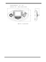
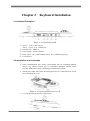
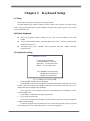
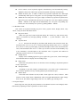
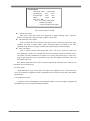
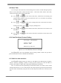
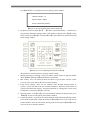
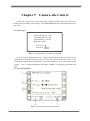
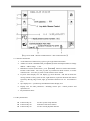
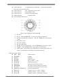
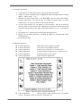
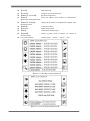
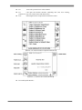
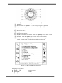
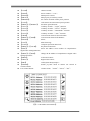
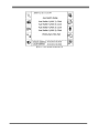
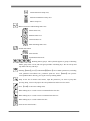
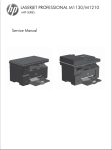
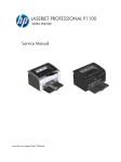
Keyboard Controller User Manual 1 Contents Chapter 1 Keyboard Instruction ..................................................................................................... 2 1.1 Support Equipments Type ................................................................................................... 2 1.2 Features ............................................................................................................................... 2 1.3 Keyboard Layout ................................................................................................................. 2 1.4 Specification........................................................................................................................ 4 Chapter 2 Keyboard Installation .................................................................................................... 6 2.1 Interface Description ........................................................................................................... 6 2.2 Installation and Connection................................................................................................. 6 Chapter 3 Keyboard Setup ............................................................................................................. 7 3.1 Setup ................................................................................................................................... 7 3.2 Enable keyboard .................................................................................................................. 7 3.3 Keyboard Loading............................................................................................................... 7 3.4 Keyboard setup ................................................................................................................... 8 Chapter 4 Matrix Control ............................................................................................................. 13 4.1 Log onto Matrix ................................................................................................................ 13 4.2 Matrix Operation Screen ................................................................................................... 14 4.3 Switching Functions .......................................................................................................... 15 4.4 Camera Control ................................................................................................................. 16 4.5 Alarm Control ................................................................................................................... 17 4.6 Macro Operations .............................................................................................................. 17 4.7 Ultra Vires Control ............................................................................................................ 19 4.8 Attributes Table ................................................................................................................. 19 4.9 Status Table ....................................................................................................................... 20 4.10 Code Distributor Protocol Setting ................................................................................... 20 4.11 Switch to other matrixes .................................................................................................. 20 4.12 OSD Setting .................................................................................................................... 21 4.13 Large Screen Splicing ..................................................................................................... 21 Chapter 5 Camera-site Control..................................................................................................... 24 5.1 User Log-in ....................................................................................................................... 24 5.3 Other Settings .................................................................................................................... 25 Chapter 6 DVR Control ............................................................................................................... 26 6.1 User Log-in ....................................................................................................................... 26 6.2 Embedded DVR ................................................................................................................ 26 6.3 PC DVR(RS-485 Communication).............................................................................. 28 6.4 PC DVR(Ethernet Communication) ............................................................................ 31 Chapter 7 Other Devices Control ................................................................................................. 36 7.1 Login Interface .................................................................................................................. 36 7.3 Control Digital Video Comprehensive Platform Host....................................................... 40 Chapter 8 Buttons Function Definition ........................................................................................ 45 8.2 Status Functions Icons Definition ..................................................................................... 47 Chapter 9 Network Update........................................................................................................... 48 1 Chapter 1 Keyboard Instruction Intelligent Network Keyboard is the controller device of surveillance system launched by our company. It supports Chinese/English operation interface and Chinese/English WEB setup interface, and can control many kinds of analog/digital surveillance equipments. 1.1 Support Equipments Type Intelligent Network Switch Speed Dome/Decoder PC Based DVR Standalone DVR Network Video Server Management Host Digital Video General Platform Screen Splicing Controller 1.2 Features Large LCD Chinese/English operation interface 3-Axis vector speed joystick Support character input, buttons with back light Matrix alarm trigger relay output Control speed dome, PTZ camera, Matrix switcher and DVR with shuttle Date Time real-time display Quick macros operation keys Password protection, support multiple user authority Ethernet and RS-485 port 1.3 Keyboard Layout 【Picture 1-1 Keyboard Front Side】 2 Area A LCD: LCD with blue back light supports Chinese/English operation interface optional, and device status/program information real-time display. Area B The Main Buttons: Green back light Red status instruction 【012„„9】 : Number and character input. 【ALM】 : Switching the alarms 【MON】 : Switching the monitors 【CAM】 : Switching the cameras 【ESC】 : Cancel 【ENTER】 : Confirm 【MULTI】 : Switching videos in DVR control mode 【LOCK】 : Lock the current camera in Matrix control mode 【MAC】 : Start or stop macroinstruction 【PROG】 : Press this button to enter into keyboard setting when the keyboard is in Login interface; Press this button to enter into PTZ setting when the keyboard is under PTZ control mode. 【AUX1~4】 : auxiliary switch 【ARM】 : Press【ARM】to enable the alarm; Press【SHIFT】+【ARM】to disable the alarm. 【ACK】 : Alarm responder 【MUTE】 : Keyboard mute button 【HOLD】 : Save 【SHIFT】 : Combination Key; 【PRESET】 : Presets setting button. Press【PRESET】+ Number to set preset positions. 【CALL】 : Press 【CALL】+ No. of presets to call upon that preset position 【SITE】 : Press this button to set the main address when the keyboard is under DVR control mode. 【PREV】 : Press【PREV】to switch camera, monitor or alarm; Press【PREV】to select the item upward in the menu setting 【NEXT】 : Press【NEXT】to switch camera, monitor or alarm; Press【NEXT】to select the item downward in the menu setting 3 Area C: Area for DVR control: 【Picture 1-2 DVR Control Area】 ① ② ③ ④ ⑤ ⑥ ⑦ ⑧ Record Play the previous video Search engine Play/suspend Low speed playback Play the next video Snapshot; Knob button: use the inside track knob to view the video by single frame; use the outside track knob to control the speed of playback. Area D: Area for extended function buttons: Press【F1】to【F10】to select icons on the LCD Area E: Area for Lens Control: Iris Open Focus In Iris Close Focus Out Zoom in Zoom out Area F: 【Picture1-3 Area of Lens Control】 Area for device selection and Matrix override control 【MODE】 : Press【MODE】to switch the control status among Matrix, DVR and PTZ 【PRI】 : Press【PRI】to enter Matrix override control Area G: 3-Axis joystick 1.4 Specification Power Supply: DC12V Power Consumption: 10W 4 Operation Temperature: -10℃~+50℃ Dimensions(mm) : 440mm×240mm×100mm 【Picture1-4 Keyboard Size】 5 Chapter 2 Keyboard Installation 2.1 Interface Description ① ② ③ ④ ⑤ 【figure 2 -1 keyboard back panel】 Port 1:A_B_G,RS-485 port Port 2:A_B_Y_Z_G,RS422 port Network port:10Base-T Power supply:DC12V/1500mA Relay output:NC_COM normally closed,NO_COM normally open For extension; 2.2 Installation and Connection 1、 Select communication port. Choose corresponding port for controlling different devices. E.g. choose network port for controlling intelligent network matrix switcher, and RS-485 port for controlling speed dome/ PTZ camera. 2、 Thread power cable and control cable through back cover, connect them the correct place and install side cover. 【figure 2 –2 keyboard installation back view】 3、 User can adjust the position by using brackets. 6 Chapter 3 Keyboard Setup 3.1 Setup Please read carefully the description of setting keyboard. All menu displayed in LED are support joystick control. Turn joystick left equal to push “ESC”; turn joystick right equal to push “ENTER”; up and down joystick equal to move cursor forward and backward. 3.2 Enable keyboard Power the keyboard without pushing any key and enter the loading screen when enable. If can‟t work normally because of joystick please push “ESC” in order to mask joystick control menu function. In loading screen, push “ MODE” select equipment and push “ PROG” load the keyboard setup. 3.3 Keyboard Loading 2008-08-12 11:25:34 Current Equipment: Matrix Communication Port: Network KeyboardIP:010.010.010.080 MatrixIP:010.010.010.050 Key<ENTER>Load equipment; <MODE>Switch equipment; <PROG> Keyboard setup; 【3 -1 Loading screen of keyboard】 1. Push “ENTER” load the current equipment. Push “MODE” switch control equipment including MAT (Matrix and Large-size screen monitors split joint control), PTZ (High speed dome), DVR, DEV (Network video server management host and digital video platform). Note: Large-size screen monitors split joint control should work with Matrix so don‟t need load Matrix first. Push “PROG” load keyboard setup program menu. 2. User‟s name and password User‟s name and password of Matrix saved by Matrix and set the relevant equipment of Matrix before loading. Load other equipment or keyboard setup, user‟s name and password saved by keyboard. Keyboard supports 8 users, pleased reference 3.4.2 User management. 7 3.4 Keyboard setup . Network setup: Set the network parameter of keyboard including IP address, subnet mask, gateway, start port, WEB port and physical address User management:It is only open to advanced administrator to amend loading of PTZ、DVR、DEV and access authority of keyboard user. Password setup: The current loading user can amend his name and password. Equipment management: Amend the relevant parameter of control equipment. Hardware setup:Set the illumination of keyboard LED, touch-tone, Matrix alarm tone and prompt tone. Delay setup:Set keyboard delay lockup, Key-press backlight delay close and delay time for closing LED backlight Key-press check; Joystick check; Hardware Display check including LED, Key-press backlight and control form light; monitor Relay check; Serial port check including RS-485 and RS-422; Shutter check; Joystick calibration: Calibrate central value of joystick, control blind area and maximum value of all directions of joystick. Time setup: Calibrate time of keyboard. Language selection: Set the language of keyboard operating screen and WEB setup screen. Now it supports Chinese and English. Note: Please carefully read Charter 8.1 before reading keyboard setup. 3.4.1 Network setup Network management IP address:010.010.010.080 Subnet Mask:255.255.254.000 Gateway:010.010.010.246 Start Port:18801 WEB Port:00080 Physical Address:00.50.C2.81.00.A0 【3-2 Network management screen of keyboard】 Setup the network parameter of keyboard: IP address can‟t conflict with other IP equipment and the default address is 10.10.10.80. Subnet mask setup should guarantee Keyboard and Matrix in the same broadcast region, and the default address is 255.255.254.0. 8 Gateway setup according to LAN setup and the default address is 10.10.10.246. Start port should same with Matrix and the default port is 18801. WEB Port retains for backup and the default port is 80. MAC default setup 00.50.C2.81.xx.xx . No need to amend normally. When editing keyboard physical address, select suitable input method by “MODE” and eliminate former parameter by “ESC” before editing and finish edit by pushing “ENTER”. After save network parameter, keyboard will suggest restart. 3.4.2 User management Keyboard supports up to 8 users including higher management, middle management, general management, higher operator and general operator. Higher management can set all parameter of keyboard and without the right to operate “user management”. Each user has three state, that is normal, freeze and cancel. User under normal can load; user under freeze can‟t load but the password and right saved; user under cancel means without using. Higher management can edit these. Push “PREV” and “NEXT” switch control right and user‟s state. Note: The default user 1 is higher management and his state is normal. Password is “000000”. The type and state of user 1 can‟t amend but can change password. 3.4.3 User‟s password management Load user can change his load password. 3.4.4 Network equipment management Equipment management Type of equipment:Matrix Matrix 1 IP:010.010.010.050 Matrix 2 IP:010.010.010.051 Matrix 3 IP:010.010.010.052 Matrix 4 IP:010.010.010.053 Matrix 5 IP:010.010.010.054 Matrix 6 IP:010.010.010.055 Matrix 7 IP:010.010.010.056 Matrix 8 IP:010.010.010.080 It is conflict with keyboard IP address, please amend. 【3-3 Equipment management screen】 Keyboard switch control equipment including MAT (Matrix and Large-size screen monitors split joint control), PTZ ( High speed dome), DVR, DEV ( Network video server management host and digital video platform). 1、 Push and switch control equipment including DEV; 9 MAT、PTZ、DVR and 2、 Push number bottom to amend IP address or and to amend unit setup. 3、 On MAT keyboard supports IP address of 8 Matrix in total. When system have several network Matrix controlled by the same keyboard, it can switch directly to the Matrix needed control in Matrix control screen. If IP address of Matrix and keyboard of customer wanted, keyboard display “ IP address conflict please amend” and suggest customer to amend IP address of Matrix. 4、 On PTZ protocol including PELCO-P、PELCO-D,baud rate supports 600、1200、2400、 4800、9600、19200、38400. 5、 On DVR, protocol is PC_DVR and EM_DVR. 6、 On DEV, model is EAS and CMS that is network video management host and digital video plat room. 3.4.5 Hardware setup Setup the illumination of LED, touch-tone, alarm tone and prompt tone. Alarm tone is when keyboard connect with Matrix and it alarm the keyboard will sound singing automatically, user can close manually. Prompt tone is if operation of keyboard is abnormal it will sound singing. Hardware setup Illumination: 1====|==3 Touch-tone:[√]-2 Alarm tone:[×]-5 Prompt tone:[×]-8 【3-4 Hardware setup screen】 Push【1】 , Illumination of screen decrease, Push【3】 ,illumination of screen increase. Push【2】 ,Touch-tone take effect or prohibit. Push【5】 ,Alarm tone take effect or prohibit. Push【8】 ,Prompt tone take effect or prohibit. Push ,Save setup and exit; Push not save and exit. 3.4.6 Delay setup Delay setup Control screen lockup delay: 003(min) Illumination of LED close delay: 010(min) Light of key-press scale delay: 010(min) Note: Delay time is 0, automatically or close light. it can‟t 【3-5 Delay setup screen】 10 lockup In the control screen keyboard supports manual-lockup and automatically lockup. Within the delay time without any operation keyboard will lockup automatically. Within the delay time of LED, if without any operation keyboard close LED light automatically and in power saving state. User can open light with pushing any bottom. Within the close delay time of key-press light, if without any operation keyboard close light of key-press automatically and in power saving state. User closes light by pushing SHIFT + MUTE. If the light closed automatically user can open it by pushing any bottom; if it close manually user open it by pushing SHIFT + MUTE. 3.4.7 Hardware check Self- check of keyboard including key-press check, joystick check, display check, relay check, serial port check and shutter check. Key-press check When user push any bottom keyboard display the current key and relevant name. Check of Assemble key through pushing Assemble + 1; push Assemble + ESC exit checking. Joystick check X、Y、Z means left and right, up and down and amount of movement of whirl. The maximum value of X、Y is 63, Z is 7. when joystick being still the value of X、Y、Z should be 0; if not 0 or move joystick slight, joystick should adjust central value and control fade zone; if the maximum value of X、Y、Z can‟t up to 63 and 7 or before to the boundary it up to the maximum, it should adjust to the maximum value of joystick. The method of adjusting joystick reference to “Joystick adjust”. Display check Display check including light of key-press, light of key-press state, control form light state and LED. Observe display state according to tips. Relay check In the back of keyboard, there is cut and close action according to keyboard operation of relay output port. Serial port check According to tips and computer communication it can check if the communication have hardware problem or not by checking RS-485 port and RS-422 port. Shutter check The inside track of shutter is JOG, it add 1 when right- turn 1 unit, it reduce 1 when left-turn 1 unit; outside track is SHUTTLE, when turn right SHUTTLE the angle change from 0 to 70, turn left the angel change from 0 to -70, and the gap of change is 10. 3.4.8 Joystick adjust Under long time using the physical parameter of mechanical structure will changed, and it will amend by adjusting in order to guarantee accurate control. 11 Joystick adjust The current value Central value Up and down: 0671 0672 Left and right: 0679 0677 Whirl: 0670 0671 Fade zone:80 Key <1> Central value adjust <2>Fade zone adjust <3>The maximum value adjust 【3-6 Joystick adjust screen】 Central value adjust: The current value and central value displayed is digital sampling value of joystick. Release joystick push 1 bottom in order to adjust central value. The maximum value adjust: Push 3 bottom enter the maximum value adjust screen. Forward joystick to the upper boundary and push 3 bottom finish “upper” maximum adjust. According to the same operation finish “down, left, right, clockwise spin and backward” maximum adjust. Fade zone adjust: Push 2 bottom controls and amend fade zone. Fake zone means the circle area surrounding the joystick axes, which do not effect the operation of keyboard. If fade zone is too small it will cause malfunction of control; if it is too big the control range is vague. So it suggests that setup the value of up and down up to the one eighth of maximum value, and the default value is 80. Note: Please adjust the central value in advance and then the maximum value otherwise the maximum value will inaccuracy. 3.4.9 Time adjust Keyboard built-in clock circuit which can adjust time displayed in the control and setup screen of keyboard in equipment. When control Matrix time of keyboard will unity with Matrix automatically. 3.4.10 Language selection It supports Chinese and English. If select English, display screen will change to English and the WEB setup screen of keyboard loading is English. 12 Chapter 4 Matrix Control In order to control matrix, users need to correctly set Network Management and Device Management, besides, users need to log onto matrix through WEB, and go through Keyboard Device Registration and User Registration (please refer to corresponding chapters in Matrix User‟s Manual). After successful completion of above settings, users can log onto matrix via keyboard and is able to control matrix. 4.1 Log onto Matrix Keyboard is able to detect whether the matrix is on line. When the matrix is off line, the communication status mark on the lower right corner of the screen is static. In the meantime, the screen will display a hint “The matrix is off line, please log onto other matrixes”. At this moment, user can choose other matrixes in the list through 【PREV】and【NEXT】. 2008-08-12 11:25:34 Current Device:Matrix Communication Port:Network Keyboard IP:010.010.010.080 Matrix 2 IP:010.010.010.051 Press<ENTER>to log on; <MODE>to switch; <PROG>to set keyboard; The matrix is off line, please log onto other matrixes 【Picture 4-1 Log onto Device】 Choose a correct matrix and check the communication status mark on the lower right corner, if it‟s radiating, nor is there any hint on the screen that the matrix is offline, then the network connection between the keyboard and the matrix is normal. Press【Enter】to go through user verification. If there is no matrix accessible, please check network connections and related settings. Note:User name and password used to log onto matrix belong to the matrix, and are different from those for logging into the keyboard. Current Device:Matrix Communication Port:Network Keyboard IP:010.010.010.080 Matrix1 IP:010.010.010.050 User:01 Password: 13 Communication status mark 【Picture 4-2 Log onto matrix】 If the log-in is abnormal, the following hints can be seen: “Communication failed, please re-log-in!”:The keyboard has not been registered in the matrix or network communication has problems, please check Network Management and Device Management in matrix, as well as the network connections. “Password error, please re-enter!”:Password verification failed, please double-check and re-enter. “User conflict, please re-enter!”:The user ID has been used on other keyboard for logging into matrix, since one user cannot log-in from different keyboards simultaneously, please use other user ID to log-in. “User does not exist, please re-enter!”:This User ID has not been registered in matrix, please register first through web. “No assigned monitor, please change settings in matrix!”:There is no monitor assigned to the subarea where the keyboard is assigned. Please log onto matrix through WEB and change settings in matrix. 4.2 Matrix Operation Screen 【Picture 4-3 Matrix Control Screen】 1、 Extended Function Buttons:On both sides of the screen, Buttons named F1~10 are extended function buttons. Functions of these buttons vary under different status. Please refer to 8.1 《Definition of Extended Function Buttons》of chapter 8 for details. 2、 Alarm Point:Press【ALM】to switch cursor to ALARM line,input numbers or press【PREV】【 / NEXT】to switch back and forth. Following icons are for alarm arming, alarm triggering and alarm status. When alarm triggers, time of alarm triggering will be shown beneath alarm point number. 14 3、 Monitor Numbers:Press 【MON】to switch cursor to MON line,input numbers or press【PREV】/【NEXT】to switch back and forth. Following icons are for monitor locked status and default macro enabled status. Inside the monitor locked status icon is the user ID which locked the monitor. If the ID is „SY‟,then monitor is locked by system, i.e. locked through macro command execution. Users with authority to control this monitor are all able to unlock this monitor. 4、 Cam Number:Press【CAM】to switch cursor to CAM line,input numbers or press【PREV】【 / NEXT】to switch back and forth. Following icons are for video status, locking status and default macro enabling status. Video status icon detects whether video input is available for the current camera, if so, a camera icon will be shown. Inside the locking status icon is the user ID which locked the monitor. If the ID is „SY‟,the camera is locked by system, i.e. locked through macro command execution. Beneath camera number is description for this camera. Matrix can overlay two lines of words for each input, here shows the second line. Only original user or those with higher authority can unlock the camera. High authority users can also unlock the camera through ultra vires control. 5、 The current camera is connected to 8 contact closure:Press【AUX1】~ 【AUX4】and extended function buttons F5~F8 to operate,● means OPEN, ○ means CLOSED. 6、 Joystick Status Display:Except for displaying joystick moving direction, X/Y/Z measures the movement of joystick‟s left and right, up and down and rotation. Range for left and right, up and down is 0~63,and rotation 0~7. 7、 Tips display area : Operation tips, operation abnormal display area. Operation abnormal messages will be cleared by pressing any button or to wait 3 seconds. 8、 User ID:Current user ID. 9、 Keyboard IP:IP address for current keyboard. 10、 Keyboard locking status mark. 11、 Communication status mark: it should be radiating when the keyboard is properly connected to matrix. 4.3 Switching Functions Switching cameras and monitors is a major function of matrix switcher. The keyboard is support multi-approaches to switching functions. 1、 Enter camera numbers:Firstly, to choose a monitor. Press【MON】, then input the monitor number and press【ENTER】or press【PREV】/【NEXT】to switch monitor numbers. Once monitor is confirmed, press【CAM】and input camera number. If the input is invalid, hints will pop up on keyboard screen. 2、 Press 【PREV】/【NEXT】 :Once monitor is confirmed, press【CAM】and then press 【PREV】/【NEXT】. 3、 Turn shuttle: The outer ring is for switching monitors, and the inner ring is for switching cameras. 15 4、 Extended function buttons : Keyboard support scene switching and synchronized switching. Firstly, press a) ,switching control window will pop up: scene switching:press ,follow the tips and press【PREV】/【NEXT】 to switch to scene related cameras of the current camera to the current monitor. If the current camera has no related scene camera, hints will pop up indicating abnormal. Press【ENTER】or【ESC】to save and exit. b) ,input monitor number and camera number, synchronized switching:Press send commands following tips. E.G. If the input monitor number is m and camera number is n, by pressing 【1】, matrix will switch camera 1 to monitor m, camera 2 to monitor(m+1), camera 3 to monitor(m+2)„„camera 10 to monitor (m+9) 5、 In addition, user can use switching functions by editing macro and calling macro. Please refer to corresponding chapters in Matrix User‟s Manual. 4.4 Camera Control The keyboard support major functions of speed domes/ PTZ receivers, specific functions will subject to the protocols of the speed domes/PTZ receivers. 1、 PTZ control:the back and forth, left and right movement of joystick is linked to pan/tilt movement. The speed is divided into 0~63 levels. Turning joystick counter-clockwise is zooming out while turning clockwise is zooming in. For the definition of lens control functions, please refer to chapter one. 2、 Preset-calling:Press【PRESET】【 / CALL】to complete preset setting and calling. Preset range is 1~255. 3、 Aux switch control:Keyboard supports 8 aux switches, among them 【AUX1】~ 【AUX4】is assigned to the first four aux switches(usually light, brush, power and auto scan.) ;extended function buttons / / / are assigned to the last four 4、 Speed dome control:press extended function button to enter the window. This aux switches. function is currently only available in special protocols. a) :call cruising tracks of the current camera, 8 in total. b) :call pattern tour of the current camera, 8 in total. c) :call auto scan of the current camera, 8 in total. d) :stop cruising track, pattern tour and auto scan. 16 4.5 Alarm Control 1、 【ARM】 :Arm and disarm the current camera. When the current camera is in arming status, the backlight of button will turn red; 2、 【SHIFT】+【ARM】 :Arm and disarm all cameras in the alarm sub area where is keyboard is assigned. 3、 【ACK】 :Respond to alarm. When alarm is triggered, the backlight of button will turn red. 4、 【SHIFT】+【ACK】 :Respond to all alarms in the current alarm sub area. 5、 【MUTE】 : Press【MUTE】to stop the buzzing of keyboard after alarming. 6、 Relay output:When matrix alarms, keyboard relay automatically opens, normally open is closed, normally closed is open. Press【MUTE】to shut down relay output. Alarm Attributes table:Press and then to enter Alarm attributes table. It is a information table for all alarm sensors, the same as the information in WEB settings. If the user is a administrator, he can even set alarm link to macro. Alarm Status Table:Press and then to enter Alarm Status Table,showing all alarm details and alarming cameras in the current alarm sub area. 4.6 Macro Operations 1、 Monitor default macro:Press 【MON】to focus on monitor, press【MAC】to open or close the current monitor default macro. The status of monitor default macro is shown by both the icon after the monitor number and the red LED light of button 【MAC】 ,the default macro is open when the LED light is on. 2、 Camera default macro:Press【CAM】to focus on camera,press【CAM】to open or close the current camera default macro. The status of camera default macro is shown by both the icon after the camera number and the red LED light of button 【MAC】 ,the default macro is open when the LED light is on. 3、 Macro calling:Press【SHIFT】+【MAC】to call or end a macro. Pre-defined macro buttons are quick access to macro calling, please refer to the following for details. Note:when ending a macro, camera number and monitor number are required. The input shall correspond to those when calling the macro, otherwise, the macro will not end. If user forget the camera number and monitor number, it is suggested that he end macro in the macro status table. 4、 Macro status table:Press and then shows all macros that are running in matrix. Press 17 to enter macro status table,which to stop a macro from running. 5、 Macro setting table:Press and then to enter macro setting table. Firstly, input macro number to enter the following window: Macro0001 Name:switch test series12 -------------------------------------------------No comd para1 para2 para3 001 SWD 00021 002 DWL 00003 003 SWD 00024 004 DWL 00003 005 LOP description:delay para sec and execute next command para:second 按键:<1>编辑名称<2>编辑权限 【Picture 4-4 Macro setting table】 a) b) Press【1】 :edit macro name, press【ESC】to clear original name;Press【ENTER】 to save data and exit; Press【2】 :assign authority to matrix users for controlling this macro: Mac 0001 User-Authority -------------------------------------------------01-√ 02-× 03-× 04-× 05-× 06-× 07-× 08-× 09-× 10-× 11-√ 12-√ 13-√ 14-√ 15-√ 16-√ 17-√ 18-√ 19-√ 20-√ 21-√ 22-√ 23-√ 24-√ 25-√ 26-√ 27-√ 28-√ 29-√ 30-√ 31-√ 32-√ 33-√ 34-√ 35-√ User:02 Authority: 【Picture 4-5 Authority Editing Window】 √ to grant authority,× to deprive authority. When editing, firstly input user number, then press【ENTER】to edit authority. Press【PREV】【 / NEXT】to switch and press【ENTER】to exit. c) Edit order of commands:Press to delete the current command, with pressing【SHIFT】, it will delete all macro commands; d) or is for inserting a command before or after the current command. Save macro:After the completing of macro editing, including macro name, authority and commands, it is imperative to press 18 for saving the macro. System will automatically exit after saving all data. 6、 Extended custom button:Keyboard supports 4 sets of extended custom buttons 、 、 ,each includes 9 specific function buttons. Press 、 to call a macro. When a macro is called, the button will change into reverse video. Press the button again to stop. Press +【SHIFT】to change the function of this extended custom button, including monitor number, camera number and macro number. Macro number is shown in the button. 4.7 Ultra Vires Control Press【PRI】to enter ultra vires status. Under this status, user can control any camera that is being controlled by users with lower authority, meanwhile, can unlock the locked monitors. Press 【PRI】again or wait for 8 seconds, system will exit from ultra vires control status.【PRI】button backlight will turn red when under ultra vires control status. 4.8 Attributes Table When user log on to matrix through keyboard, keyboard will collect detailed information of matrix(including cameras, audio, monitors, alarm) ,and save it to keyboard for user‟s review. Therefore, user could review matrix information and make simple settings for matrix on keyboard.。 Press ,then to enter alarm attributes table. Alarm attributes table shows details of all alarm sensors, the same as information on Web setting. Administrator can edit the information. Press ,then to enter monitor attributes table. Monitor attributes table shows details of all monitors, the same as information on Web setting. Administrator can edit the information. Press ,then to enter camera attributes table. Monitor attributes table shows details of all cameras, the same as information on Web setting. Administrator can edit the information. Press ,then to enter audio attributes table. Audio attributes table shows details of all audios, the same as information on Web setting. Administrator can edit the information. Press ,then to enter macro attributes table. Macro attributes table shows details of all macros, the same as information on Web setting. Administrator can edit the information. 19 4.9 Status Table User can inspect and control the current running status of matrix switcher through keyboard. There are four status table to show the matrix status.:alarm status table, monitor status table, camera status table, macro running status table. Press ,then to enter alarm status table, which shows all alarming and alarming camera numbers in the current alarm sub area. User can disarm, end alarming of single camera or all cameras. Press ,then to enter macro running status table, which shows all macros running in the matrix. Press Press to stop any running macro. ,then to enter monitor status table, which shows current status of all ,then to enter camera status table, which shows current status of all monitors. Press cameras. 4.10 Code Distributor Protocol Setting Device Type:code distributor protocol:PelcoD baud rate:2400 PROG-set up,ESC-exit 【Picture 4-6 Code Distributor Protocol Setting】 Press【PROG】to enter code distributor protocol setting window. Follow the tips and set protocol and baud rate for the embedded code distributor. 4.11 Switch to other matrixes Press【SITE】to display matrix lists. There are 8 IP addresses for different matrix switchers. Choose a matrix by inputting a number or moving joystick, then log in. If the IP address is invalid, or this matrix is offline, there will be hints saying log-in not allowed. Note:For the first time the keyboard logs onto the chose matrix, user needs to enter user ID and password. However, if it is not the first time after the keyboard is powered up, keyboard will log onto matrix automatically using the same user ID and password that were used in previous time. 20 2008-08-12 13:45:26 matrix1 IP: 010.010.010.050 matrix2 IP: 010.010.010.051 matrix3 IP: 010.010.010.052 matrix4 IP: 010.010.010.053 matrix5 IP: 010.010.010.054 matrix6 IP: 010.010.010.055 matrix7 IP: 010.010.010.056 matrix8 IP: 010.010.010.057 Input NO.1-8 to choose corresponding matrix 【Picture 4-7 Switch to other matrixes】 4.12 OSD Setting If user is senior admin, he could enter OSD Setting by pressing【SHIFT】+【PROG】 and entering user ID and password. One matrix allows only one user to enter OSD setting simultaneously. If another user has already entered OSD Setting mode, or the current user‟s authority is high enough, there will be hints on the keyboard screen. OSD menu is conducted mainly through number buttons,【ESC】、 【ENTER】, joystick and shuttle. Please refer to OSD Setting Instruction manual for details. 4.13 Large Screen Splicing Large screen splicing requires matrix, keyboard and splicing controller. Connect the video output of matrix to the input port of splicing controller. Connect the RS-485 port on keyboard to the port on splicing controller. Press【MULTI】on keyboard to enter splicing control window. Also user can go back to matrix control window by pressing【MULTI】again. Keyboard support any combination of screen wall within the range of 8×6 and 2×2, and 7 groups of self-customized splicing buttons. User can edit the specification of screen wall and function of splicing buttons. User can also control cameras and splice screens in splicing control window. Operation Procedures: 1、 Press【MULTI】to enter splicing control window. 2、 Press【F10】 “splicing settings” to enter settings for screen wall specifications and splicing buttons. a) Press【F8】 “edit specifications” to edit the screen specification of splicing unit as follows. Input numbers in corresponding places, minimum 2×2,maximum 8×6. 21 【picture 4-8 settings for screen wall specifications and splicing buttons】 b) Press【F9】 “set splicing buttons” to edit splicing buttons as follows. Move joystick to choose the start position of the splicing unit, and press【LOCK】 to confirm. Then choose the end position and confirm. Now, the lines between screens disappear, which means a splicing unit is completed. Video in the original starting screen is retained and expanded into the splicing unit. User can set 4 more splicing units by repeating the above procedures. After the completion of the setting, press any button between【F1】 and【F7】, this button is customized. a figure reflecting the corresponding splicing unit will be shown beside each button. In this way, one splicing button can automate complex splicing settings. Each button includes maximum 5 groups, as shown by the following picture. 【Picture 4-9 specifications and button setting window】 c) Press【F10】to save settings for specifications and splicing buttons and exit to splicing control window. 3、 Press【PROG】to enter unit relations window. User can set the relations between video outputs of matrix with monitors, according to the practical connections. For example, monitor number 11 relates to the first channel of matrix output, while monitor number 21 relates to the second channel of matrix outputs„„. After the completion of settings, 22 press【PROG】to save settings and exit to splicing control window. Monitor number:21 Matrix output:00002 Please confirm the relations 【Picture 4-10 screen splicing unit relations window】 4、 In splicing control window,【F1】~【F7】are customized buttons.(customized in specifications and button setting window, each includes 5 splicing units) 【F8】is quick button for full-screen.【F9】is reset button.【F10】is a quick button for specifications and button setting window. 【Picture 4-11 screen splicing unit relations window】 Main functions and instructions in splicing control window: 1、 Monitor and camera switching:Same as in matrix control window. It supports number inputs,【PREV】button and【NEXT】button, and shuttle. 2、 PTZ control:User can control the PTZ movement of speed dome cameras or PTZ receivers when cursor falls on the area of camera numbers. 3、 Large screen splicing:There are two methods, either through splicing buttons or joystick(cursor must fall on the area of monitor numbers, otherwise, the movement of joystick will lead to PTZ control). It supports maximum 11 splicing units. If user wants to add more, he must press【F9】to reset first. 4、 Splicing settings:Press【F10】to enter specifications and button setting window, press 【PROG】to enter screen splicing unit relations window. 5、 Joystick operations:Joystick has two main functions: PTZ control and splicing control. If user needs to make PTZ control, he must press【CAM】to move cursor to the area of camera numbers. If user needs to make splicing control, he must press【MON】to move cursor to the area of monitor numbers. 23 Chapter 5 Camera-site Control Camera-site Control means using keyboard to control speed dome camera or decoder via RS-485 or RS-422 directly. After starting,press【MODE】button to switch controlled devices to PTZ mode. 5.1 User Log-in Camera-site Devices:PTZ Communication Port:485 Control Protocol:PelcoP Baud Rate:9600 User Code:01 Password: 【Fig 5-1 Log-in Interface of Camera-site control】 As tot eh setup of communication port、control protocol、baud rate, please refer to the device management in keyboard parameter setup: and user code and password, please refer to user management and password management in keyboard parameters setup. The default factory settings: User 1 is advanced administer, password is“000000” 。Please change password in due time. 5.2 Control Operation 【Fig 5-2 Control operation main interface】 24 1、 Extended function buttons area,functions of 【F1】~【F10】 are speed dome auto cruising、 pattern tour、auto scan、stop above speed dome motion、track call、auxiliary switch 5~8 and exit PTZ control. Except for【F4】button, all other extended functions needs special protocols supports. Note:Regular operations of camera site control can be performed via 【CALL】/ 【PRESET】and joystick lens button on the keyboard. 2、 Current controlled camera,and the mark after it is track call mark, which means that the keyboard is performing the track call operation to this camera,and the number after the mark is the track number;as to the track edition, please refer to“other settings” as follows。Input the camera number or press 【PREV】/【NEXT】button to switch controlled camera. 3、 There are 8 auxiliary switch status under this camera:Perform control operation via pressing 【AUX1】~【AUX4】 and extended function auxiliary switch buttons 5~8 (Usually related to four camera site device functions: Light、Rain brush、power、Auto Scan) ,● means open,○ means shut. As to work under pressing and keep working status of the auxiliary switch, please refer to“Other settings” in the following text. 4、 Joy-stick status display area can display joy-stick direction,and X/Y/Z means the moving amount of the joystick on left, right direction, up down direction and rotation separately. Moving range on left, right, up and down direction is 0~63,and rotation is 0~7。 5、 Tips display area:operation tips and abnormal status display area. 6、 Display area for other parameters,including current port、control protocol and operation user. 7、 Keyboard lock status。 5.3 Other Settings 1、 As to communication port、control protocol、baud rate setup, please refer to device management in the keyboard settings. 2、 Auxiliary switch and track setup:Press 【PROG】 and select setup option, Auxiliary Switch:Set auxiliary switch control type for PTZ camera control. Working when pressing:press to close auxiliary switch,and release the button to shut auxiliary switch;Keep working status:Press the button to close auxiliary switch,and release the button not to shut auxiliary switch; press the button again to shut auxiliary switch. Track Program: 30 track, each with 128 steps of preset positions are supported,and pause time for each step is from 1 to 240 seconds. In the track program interface, make the program via 【F1】~. 【F10】 buttons, and press 【F9】 to save. 25 Chapter 6 DVR Control This keyboard support control of embedded DVR via RS-485,and control of PC DVR via Ethernet or RS-485。After starting, press【MODE】to switch from the control devices mode to DVR mode. 6.1 User Log-in Current Device:DVR Communication Port:485 Control Protocol:PC_DVR Baud Rate:9600 User Code:01 Password: 【Fig 6-1 Log-in Menu of DVR Control】 Find setup of communication port、control protocol、baud rate in devices management in keyboard parameter setting。PC_DVR means the controlled device is a PC DVR,EM_DVR means embedded DVR。 As to user code and password, please refer to User Management and Password Management in Keyboard Parameters Settings。The factory default setup: user 1as advanced administrator, and password“000000”. 6.2 Embedded DVR 【Fig 6-2 Main menu of EM DVR Control】 26 6.2.1 Menu Instruction 1、 As to detailed functions of function buttons, please refer to button instruction. 2、 Address of current controlled DVR: press【SITE】 button and input numbers to change address,address range:1~31. 3、 Indication of current control status,press 【MODE】 button to switch between “Camera-site Control”and“Control Menu”. In camera-site control mode,move the joy-stick to perform camera-site PTZ dome motion;in Control Menu mode1,move the joy-stick to perform the direction selection; up, down, left, right, in the DVR menu。 4、 Joy-stick status display area can display joy-stick direction,and X/Y/Z means the moving amount of the joystick on left, right direction, up down direction and rotation separately. Moving range on left, right, up and down direction is 0~63,and rotation is 0~7。 5、 Tips for joy-stick mode。 6、 Display area for other parameters,including current port、control protocol and operation user. 7、 Keyboard lock status:if the keyboard is not locked,then there will be no mark here. 6.2.2 Button Function Function Key F1: To enter DVR system setup interface(The same as the“Main Menu”button on the front panel of DVR) Function Key F2: Start record(The same as“Record”button on the front panel of DVR) Function Key F3: To enter record playback interface ( The same as “Playback”button on the front panel of DVR) Function Key F4: To enter PTZ control(The same as “PTZ Control”button on the from panel of DVR) Function Key F5: Return to the operation menu of the last level(The same as “Exit”button on the front panel of DVR) Function Key F6: Description of Edit Menu(The same as “Edit” button on the from panel of DVR) Function Key F7: Input method switch(The same as “Input Method”button on the front panel of DVR) Function Key F8: Shut down DVR(The same as the power button on the front panel of DVR) Function Key F10: Exit DVR control 【0】~【9】 : Number buttons(The same as the number buttons of“0”~ “9”buttons on the front panel) 【ENTER】 : Confirm(The same as “Confirm”button on the front panel of DVR) 【MULTI】 : Multi pictures switch(The same as the “Multi Pictures” button on the front panel of DVR) 27 【PROG】 : edit the status of aux switches 【AUX1】 : Lights(The same as the “Lights”button on the front panel of DVR) 【AUX2】 : Power(The same as the“auxiliary”button) 【AUX3】 : Rain Brush(The same as the “Rain Brush”button on the front panel of DVR) 【SITE】 : Change DVR address 【SHIFT】+【LOCK】 ::Lock Keyboard 【MODE】 : Select joy-stick control mode Lens Control Button: Lens control(The same as the“Iris”、 “Focus”、 “Zoom” buttons on the front panel of DVR) 【Fig 6-3 Auxiliary Switch Setup Interface】 6.2.3 Connection and Use As there are many RS-485 interfaces on DVR host , please connect the right communication port with RS-485 port on the keyboard in the correct way referring to user‟s manual of DVR. When several DVR‟s connect with the keyboard,please connect DVR communication ports with interfaces on keyboard,Adopt daisy chain to connect DVR communication port with keyboard port a maximum of 30 sets of DVR hosts cascading are supported。 Refer to DVR user‟s manual,and set the right address ID in DVR programming menu。 Control is available, when the DVR address display on the keyboard is the same as the address of the DVR host。 6.3 PC DVR(RS-485 Communication) 28 【Fig 6-4 PC DVR(RS-485 communication)main control interface】 6.3.1 Interface Instruction 1、 As the functions of function keys, please refer to the button instruction. 2、 Address of current controlled DVR: press【SITE】 button and input numbers to change address,address range:1~255. 3、 Indication of current control status,press 【MODE】 button to switch control modes. In PTZ control mode,move the joy-stick to perform PTZ dome motion;in mouse control mode1,move the joy-stick to control mouse arrow motion. 4、 Joy-stick status display area can display joy-stick direction,and X/Y/Z means the moving amount of the joystick on left, right direction, up down direction and rotation separately. Moving range on left, right, up and down direction is 0~63,and rotation is 0~7。 5、 Tips display area:operation tips and abnormal status display area. 6、 Display area for other parameters,including current port、control protocol and operation user. 7、 Keyboard lock status。 6.3.2 Key Instructions Function Key F1: Function Key F2: Function Key F3: To enter system setup interface Function of left mouse button To enter record playback interface 29 Function Key F4: Joy-stick functions switch button,joy-stick can control PTZ and works as the left mouse button Function Key F5: Exit,and return to previous level Function Key F6: Input methods switch Function Key F7: Works as mouse right button Function Key F10: Exit DVR contro Record playback function key: ① ② ③ ④ ⑤ ⑥ ⑦ ⑧ ⑨ 【Fig 6-5 Record Playback Control Buttons】 Stop play; Record,work with【SHIFT】 to start or stop record of all channels; Play the last period part of record file,work with 【SHIFT】 to turn down the volume; Record files search; Play pause/continue; Play speed adjustment; Play the next period of record file,work with【SHIFT】to turn on the volume; Snapshot,work with【SHIFT】to capture pictures in all channels; Shuttle button,when playing file, inside shuttle to control single frame view search,outside shuttle to control forward and backward speed; Definition of other buttons: 【0】~【9】 : 【ENTER】 : 【ESC】 : 【CAM】 : 【MON】 : 【MULTI】 : 【PROG】 : 【PRESET】 : 【CALL】 : 【SHIFT】+【PRESET】 : 【AUX1】 : 【AUX2】 : 【AUX3】 : Number buttons Confirm; Backspace; Channel switch; Select windows(1~25) ; Multi-picture switch; Edit property of auxiliary switch; Set camera site PTZ camera preset position Call camera site PTZ camera preset position Set/delete guard location; Auxiliary switch 1, “Light”function Auxiliary switch 2, “Power”function Auxiliary switch 3, “Rain Brush”function 30 【AUX4】 : Auxiliary switch 4, “Auto”function 【ARM】 : Activate/clear alarm of current channel; 【SHIFT】+【ARM】 : Activate/clear alarm of all channels; 【MUTE】 : Silent; 【ACK】 : Shut alarm ring; 【LOCK】 : Computer operation menu lock; 【SHIFT】+【LOCK】 : Keyboard control lock 【SITE】 : Select the address series number of comprehensive digital video management host; 【SHIFT】+【SITE】 : Change the IP address of comprehensive digital video management host; 【PREV】 : Left mouse button; 【NEXT】 : Right mouse button; 【PRI】 : Call keyboard Pinyin input ; 【MODE】 : Switch joy-stick mode as camera site control or control software Lens control button : Control of lens “Zoom” 、 “Focus” 、 “Iris” 。 6.4 PC DVR(Ethernet Communication) 【Fig 6-6 PC DVR(Ethernet Communication)Control Main Interface】 31 6.4.1 Interface Instruction 1、 As the functions of function keys, please refer to the button instruction. 2、 Address of current controlled DVR: press【SITE】 button and input numbers to change address,address range:1~99. 3、 Indication of current control status,press 【MODE】 button to switch control modes. In PTZ control mode,move the joy-stick to perform PTZ dome motion;in mouse control mode1,move the joy-stick to control menu selection. 4、 Joy-stick status display area can display joy-stick direction,and X/Y/Z means the moving amount of the joystick on left, right direction, up down direction and rotation separately. Moving range on left, right, up and down direction is 0~63,and rotation is 0~7。 5、 Tips display area:Operation tips and abnormal status display area. 6、 Display area for other parameters,including IP address of keyboard and current controlled DVR. 7、 Keyboard lock status。 6.4.2 Buttons Instruction Function Button F1: Function Button F2: Function Button F3: Function Button F4: Function Button F5: Function Button F6: 【Fig 6-7 Video Parameters Adjustment Interface】 Function Button F7: Channel switch: single window switch、all windows switch、all monitors switch are optional(Extension Use) TAB button on the computer keyboard To enter the record playback interface Switch to the camera tree list(Extension Use) Open and shrink of camera tree list(Extension Use) Exit and return to previous menu Video Parameters Adjustment 32 Function Button F8: Open and shut of current channel talk Function Button F9: Call the camera site control function interface (Including auto scan、cruising、pattern tout、Stop auto、alarm check、camera menu) (Extension use) Function Button F10: Exit DVR control 【Fig 6-8 Camera Site Control Interface】 Function Buttons of Record Playback: ① ② ③ ④ 【Fig 6-9 Function button area of record playback】 Stop play; Record,work with【SHIFT】 to start or stop record of all channels; Play the last period part of record file,work with 【SHIFT】 to turn down the volume; Record files search, buttons 1~8 are for extension use; 33 【Fig 6-10 Record File Search Interface】 ⑤ Play pause/continue; ⑥ Slow play speed adjustment; ⑦ Play the next period of record file,work with【SHIFT】to turn on the volume; ⑧ Snapshot,work with【SHIFT】to capture pictures in all channels; ⑨ Shuttle button,when playing file, inside shuttle to control single frame view search,outside shuttle to control forward and backward speed; 【0】~【9】 : Number buttons 【ENTER】 : Confirm; 【ESC】 : Backspace; 【CAM】 : DVR control channel switch; 【MON】 : Select windows(1~25) ; 【MULTI】 : Multi-picture switch; 【PROG】 : Edit property of auxiliary switch; 【PRESET】 : Set camera site PTZ camera preset position 【CALL】 : Call camera site PTZ camera preset position 【SHIFT】+【PRESET】 : Set/delete guard location; 【AUX1】 : Auxiliary switch 1, “Light”function 【AUX2】 : Auxiliary switch 2, “Power”function 【AUX3】 : Auxiliary switch 3, “DVR Rain Brush”function 【AUX4】 : Auxiliary switch 4, “DVR Auto”function 【ARM】 : Activate/clear alarm of current channel; 【SHIFT】+【ARM】 : Activate/clear alarm of all channels; 【MUTE】 : Silent; 【ACK】 : Shut alarm ring; 【LOCK】 : Computer operation menu lock; 【SHIFT】+【LOCK】 : Keyboard control lock 【SITE】 : Select the address series number of DVR; 【SHIFT】+【SITE】 : Change the IP address of DVR; 34 【PREV】 : 【NEXT】 : 【PRI】 : 【MODE】 : control software Lens control button : Left mouse button; Right mouse button; Call keyboard Pinyin input ; Switch joy-stick mode as camera site control or Control of lens “Zoom” 、 “Focus” 、 “Iris” 。 【Fig 6-11 IP Address Setup Interface】 【Fig 6-12 Auxiliary Switch Setup Interface】 35 Chapter 7 Other Devices Control The keyboard support control Network Video Server Management Host and Digital Video Comprehensive Platform Host by Ethernet control. After starting keyboard, press【MODE】to switch Control Device Type to DEV mode. 7.1 Login Interface Device:DEV Comm Port:NET Control Protocol:CMS USER ID:01 Password: 【Picture7-1 Other Device Login Interface 】 Communication Port and Control Protocol is in the Device Management of Keyboard Parameter Setup. EAS means the control device is Network Video Server Management Host, CMS means the control device is Digital Video Comprehensive Platform Host. User ID and Password please refer to User Management and Password Management of Keyboard Parameter Setup. The default user is No.1. The default password is 000000. 7.2 Control Network Video Sever Management Host 【Picture 7-2 Network Video Sever Management Host Control Interface】 36 7.2.1 Interface Instruction 1、 Function key, please refer to keys instruction. 2、 The current control Network Video Server Management Host address, press【SITE】to amend address, the scope is 1-99. 3、 Window No. of Network Video Server Management Host and Channel No. of Network Video Server. 4、 It‟s the status of joystick control, press 【MODE】to switch the control type. In P/T control status, the joystick can control P/T; In mouse control status, the joystick can control mouse. 5、 Joystick Status Display: X/Y/Z can display joystick right and left, up and down and also rotation movement. Right and left movement scope is 0-63, rotation scope is 0-7. 6、 Tips Information Display: operation tips and abnormal status display area. 7、 Other Control Parameter Display, including keyboard IP address and Network Video Server Management Host IP address. 8、 Keyboard Lock Status Marks 7.2.2 Keys Instruction F1: Enter system setup interface F2: Enter record playback interface F3: Previous page F4: Next page F5: Exist and back to previous menu F6: Input switch F7: Channels switch. Auto switch, group switch, signal Win switch and all Win switch are optional. F8: Inter-talk open and close in this channel. F9: Call upon the function interface (including auto scan, auto cruising, pattern tour, stop auto, alarm search and dome menu) 【Picture 7-3 Camera Site Control Interface】 37 F10: Exist Network Video Server Management Host Control Record playback buttons: ① ② ③ ④ ⑤ ⑥ ⑦ ⑧ ⑨ 【Picture 7-4 Record Playback Control Buttons】 Stop play; Record,work with【SHIFT】 to start or stop record of all channels; Play the last period part of record file,work with 【SHIFT】 to turn down the volume; Record files search; Play pause/continue; Play speed adjustment; Play the next period of record file,work with【SHIFT】to turn on the volume; Snapshot,work with【SHIFT】to capture pictures in all channels; Shuttle button,when playing file, inside shuttle to control single frame view search,outside shuttle to control forward and backward speed; Definition of other buttons: 【0】~【9】 : 【ENTER】 : 【ESC】 : 【CAM】 : 【MON】 : 【MULTI】 : 【PROG】 : 【PRESET】 : 【CALL】 : 【SHIFT】+【PRESET】 : 【AUX1】 : 【AUX2】 : 【AUX3】 : 【AUX4】 : 【ARM】 : 【SHIFT】+【ARM】 : 【MUTE】 : Number buttons Confirm; Backspace; Channel switch; Select windows(1~25) ; Multi-picture switch; Edit property of auxiliary switch; Set camera site PTZ camera preset position Call camera site PTZ camera preset position Set/delete guard location; Auxiliary switch 1, “Light”function Auxiliary switch 2, “Power”function Auxiliary switch 3, “Rain Brush”function Auxiliary switch 4, “Auto”function Activate/clear alarm of current channel; Activate/clear alarm of all channels; Silent; 38 【ACK】 : Shut alarm ring; 【LOCK】 : Computer operation menu lock; 【SHIFT】+【LOCK】 : Keyboard control lock 【SITE】 : Select the address series number of comprehensive digital video management host; 【SHIFT】+【SITE】 : Change the IP address of comprehensive digital video management host; 【PREV】 : Left mouse button; 【NEXT】 : Right mouse button; 【PRI】 : Call keyboard Pinyin input ; 【MODE】 : Switch joy-stick mode as camera site control or control software Lens control button : Control of lens “Zoom” 、 “Focus” 、 “Iris” 。 【Picture 7-5 IP Address Setting Interface】 【Picture 7-6 Aux Switch Setting Interface】 39 7.3 Control Digital Video Comprehensive Platform Host 【Picture 7-7 Digital Video Comprehensive Platform Host Control Interface】 7.3.1 Interface Instruction 1、 Function key, please refer to keys instruction. 2、 The current control Digital Video Comprehensive Platform Host address, press【SITE】 to amend address, the scope is 1-99. 3、 It‟s the status of joystick control, press 【MODE】to switch the control type. In P/T control status, the joystick can control P/T; In software control status, the joystick can control the software menu. 4、 Joystick Status Display: X/Y/Z can display joystick right and left, up and down and also rotation movement. Right and left movement scope is 0-63, rotation scope is 0-7. 5、 Tips Information Display: operation tips and abnormal status display area. 6、 Other Control Parameter Display, including keyboard IP address and Network Video Server Management Host IP address. 7、 Keyboard Lock Status Marks 7.3.2 Keys Instruction F1: Correspondent with TAB on PC keyboard F2: Enter record playback interface F3: Switch to list of camera site host F4: Camera site list open and close F5: Exist and back to previous menu F6: Video parameter adjustment F7: Channels switch. Auto switch, group switch, signal Win switch and all Win switch are optional. 40 F8: Inter-talk open and close in this channel. F9: Call upon the function interface (including auto scan, auto cruising, pattern tour, stop auto, alarm search and dome menu) F10: Exist Digital Video Comprehensive Platform Control 【Picture 7-8 Video Parameter Adjustment Interface】 【Picture 7-9 Camera Site Control Interface】 Record Playback Buttons: 41 ⑩ ⑪ ⑫ ⑬ ⑭ ⑮ ⑯ ⑰ ⑱ 【Picture 7-10 Record Playback Control Buttons】 Stop play; Record,work with【SHIFT】 to start or stop record of all channels; Play the last period part of record file,work with 【SHIFT】 to turn down the volume; Record files search; Play pause/continue; Play speed adjustment; Play the next period of record file,work with【SHIFT】to turn on the volume; Snapshot,work with【SHIFT】to capture pictures in all channels; Shuttle button,when playing file, inside shuttle to control single frame view search,outside shuttle to control forward and backward speed; 【Picture 7-11 Record File Research Interface】 Definition of other buttons: 【0】~【9】 : 【ENTER】 : 【ESC】 : Number buttons Confirm; Backspace; 42 【CAM】 : Channel switch; 【MON】 : Select windows(1~25) ; 【MULTI】 : Multi-picture switch; 【PROG】 : Edit property of auxiliary switch; 【PRESET】 : Set camera site PTZ camera preset position 【CALL】 : Call camera site PTZ camera preset position 【SHIFT】+【PRESET】 : Set/delete guard location; 【AUX1】 : Auxiliary switch 1, “Light”function 【AUX2】 : Auxiliary switch 2, “Power”function 【AUX3】 : Auxiliary switch 3, “Rain Brush”function 【AUX4】 : Auxiliary switch 4, “Auto”function 【ARM】 : Activate/clear alarm of current channel; 【SHIFT】+【ARM】 : Activate/clear alarm of all channels; 【MUTE】 : Silent; 【ACK】 : Shut alarm ring; 【LOCK】 : Computer operation menu lock; 【SHIFT】+【LOCK】 : Keyboard control lock 【SITE】 : Select the address series number of comprehensive digital video management host; 【SHIFT】+【SITE】 : Change the IP address of comprehensive digital video management host; 【PREV】 : Left mouse button; 【NEXT】 : Right mouse button; 【PRI】 : Call keyboard Pinyin input ; 【MODE】 : Switch joy-stick mode as camera site control or control software Lens control button : Control of lens “Zoom” 、 “Focus” 、 “Iris” 。 【图 7-12 IP Address Set Interface】 43 【图 7-13 Aux Switch Set Interface】 44 Chapter 8 Buttons Function Definition 8.1 Extended Function Buttons Definition Press【F1】to【F10】to select icons on the LCD :Turn the page forward :Turn the page backward; :Move the cursor upward on the menu; :Move the cursor backward on the menu;; :Save the current setting;The setting can only be enabled after saving :Quite from the current menu and back to the upper menu :Matrix parameter setting :Enter into PTZ control :Call upon auto cruises,8 groups; :Call upon pattern tours, 4 groups; :Call upon auto scan, 8 groups :Stop the current PTZ move. :Aux switcher; :Aux switcher; :Aux switcher; :Aux switcher; :Matrix control,setup list, including alarm point, monitor and so on :Alarm Point Parameter Setup List; : Monitor Parameter Setup List; 45 : Camera Parameter Setup List; : Audio Point Parameter Setup List : Macro Setup List; :Matrix Parameters and Running Status List: :Alarm Status List; :Monitor Status List; :Camera Status List; :Macro Running Status List; :Switch and Control :Scene Switch; :Synchronistical Switch; :Defining Macro groups. The keyboard supports 4 groups of defining Macro group from A to D, and each group includes 9 defining keys. We can call up and stop Marco directly with keys. :Defining【Macro】, press【Combination】+【Macro】can set Macro parameters, including code, parameter surveillance No., parameter point No.. Press 【Macro】can open the correspondent Macro directly, press again can stop running Macro. :Jump. In the list of monitor and camera, input the parameter you want to jump after pressing Jump, cursor will jump to the correspondent list and no need to search. :Press 【Edit】to enter into editing status :When editing list, it is used to insert a command before this list; :When editing list, it is used to insert a command after this list; :When editing list, it is used to delete this list; :Exist current control status; 46 :When controlling PTZ, it is used to open or stop current calling operation; When controlling DVR, Network Video Server Management How and Digital Video Comprehensive platform: :Input Method; :Record Playback; :Exist and back to previous menu; :Switch to tree list; :TAB keys; :Tree list open and close; :Video parameter setup; :Power off; :Left mouse; :Right mouse; :Record; :Enter into setting menu 8.2 Status Functions Icons Definition :Defense, alarm point status; :Alarm situation,alarm point status; : Alarming, alarm point status; :Lock, surveillance, point, keyboard controlling status :Video, point status; :Default Macro call upon, surveillance, point status; :When controlling PTZ, it is used to calling upon。 47 键盘用户 管理 用 户 ID(1~8) : 02 用 户 类 型:高 级管理员 用 户 状 态:正 常 编程-设 置 确定继续编辑 Chapter 9 Network Update Our keyboard supports update from internet , the methods are as following: 1) Get update files“.bin”from company; 2) Connect keyboard to computer and log on keyboard website in IE, input user‟s name and password to log on keyboard. It requires users have administrator authority. 【Picture 9-1 Network Keyboard Login Interface】 3) Open update web: system maintenance-> system update 【Picture 9-2 Network Keyboard Program Update Interface】 After updating, click Submit. And there need 20 seconds to update, please restart keyboard after updating. 48