1
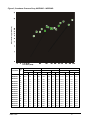
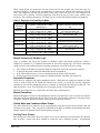
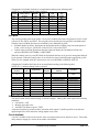
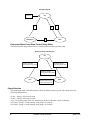
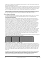
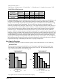
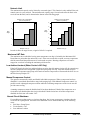
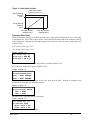
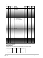
Introduction General Description Daikin Type WGZ water chillers are designed for indoor installations Equipment room temperature for operating and standby conditions is 40°F to 122°F (4.4°C to 50°C). They are available with water-cooled condensers (Model DW), or arranged for use with remote air-cooled or evaporative condensers (Model DA). Each water-cooled unit is completely assembled and factory wired before evacuation, charging and testing. They consist of hermetic scroll compressors, brazed-plate evaporator, water-cooled condenser (WGZDW), and complete refrigerant piping. Units manufactured for use with remote condensers (Models WGZ-DA) have all refrigerant specialties factorymounted and connection points for refrigerant discharge and liquid lines. Liquid line components that are included are manual liquid line shutoff valves, charging valves, filter-driers, liquid line solenoid valves, sight glass/moisture indicators, and thermal expansion valves. Other features include compressor crankcase heaters, and a MicroTech II microprocessor controller. The electrical control center includes all equipment protection and operating controls necessary for dependable automatic operation. NOTE: This manual contains information on the chiller unit control software operating with various refrigerants as follows: • R-410A, used with the current “D” vintage of the WGZ chiller. • R-134a, used with only with Model TGZ Templifiers. The operating manual devoted exclusively to Templifiers is OMM 1136. BOOT & BIOS BOOT Version: 3.0F BIOS Version 3.56 Manuals: Information in unit initial installation and routine maintenance is contained in Installation and Maintenance Manual IM 1131. Nomenclature W G Z 100 - D W Water-Cooled Global Design Scroll Compressor W = Water-Cooled Cond. A = Unit Less Cond. Design Vintage Nominal Capacity (Tons) Water Pressure Drop Water flow rates should be maintained as closely as possible to job design values. The vessel flow rates must fall between the minimum and maximum values shown on the appropriate evaporator and condenser curves. Measure the water pressure drop through the vessels at field-installed pressure taps and check the flow rate using the following tables. Do not include valves or strainers in these readings. The evaporator flow rates and pressure drops shown on the following page are for full load design purposes. The maximum flow rate and pressure drop are based on a 6-degree temperature drop. Avoid higher flow rates with resulting lower temperature drops to prevent potential control problems resulting from very small control bands and limited start up/shut off temperature changes. The minimum flow and pressure drop is based on a full load evaporator temperature drop of 16-degrees. OMM 1130-2 3